ALE USA OAW-AP122X OmniAccess Stellar AP1220 series User Manual
ALE USA Inc. OmniAccess Stellar AP1220 series
ALE USA >
Contents
User Manual
Alcatel-Lucent Enterprise
OmniAccess Stellar AP1220 Series
Installation Guide
060455-10 Re v. B
*060455-10 Rev. B*
enterprise.alcatel-lucent.com
Alcatel-Lucent and the Alcatel-Lucent Enterprise logo are trademarks of Alcatel-Lucent. To view
other trademarks used by affiliated companies of ALE holding, visit:
enterprise.alcatel-lucent.com/trademarks. All other trademarks are the property of their
respective owners. The information presented is subject to ALE without notice. Neither ALE
Holding nor any of its affiliates assumes any responsibility for inaccuracies contained herein.
(2017)
Summary of installation Steps
• WLAN Planning. Usually, a comprehensive site survey is required
before installation, such as installation location, brackets, cables,
power source, etc.
• Unpack the AP box and check all contents
• Install the AP bracket on ceiling or wall
• Installing the AP
• Connecting required cables
• Power connection
• Verifying post-installation connectivity
• AP provisioning
AP is a radio transmission device and subject to governmental regulation.
Network administrators must comply with local regulations.
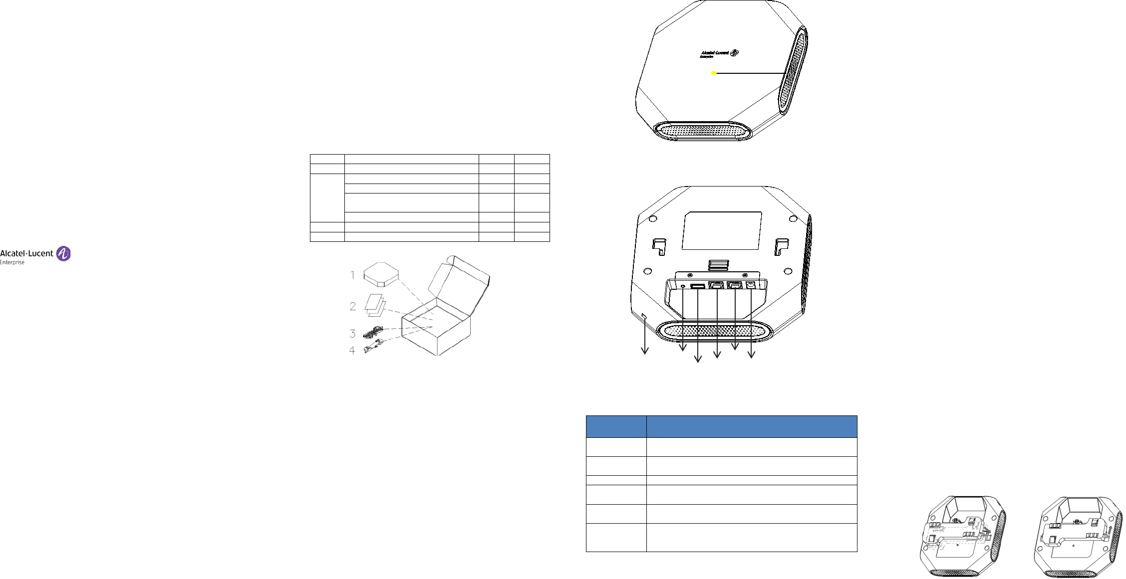
Package Contents
Item
Name
Qty
Unit
1
Access Point
1
Pcs
2
Quick Start Guide
1
Pcs
Installation Guide
1
Pcs
Regulatory Compliance and Safety
Information
1 Pcs
User Guide Info Card
1
Pcs
3
Mounting Bracket (15/16”)
1
Pcs
4
Mounting Bracket (9/16”)
1
Pcs
Figure1: AP Packing
Inform your ALE sales representative of incorrect, missing, or
damaged parts. If possible, retain the carton, including the
original packing materials. Use these materials to repack and
return the unit to the supplier if needed. Additional mounting
kits for use with the OmniAccess Stellar AP1220 series access
points are sold separately. Contact your ALE sales representative
for details.
Unpack OAW-AP1221 or AP1222 box:
• AP Dimensions: 180mm (W) x 180mm (D) x 36mm (H) -7.08”
(W) x 7.08” (D) x 1.41” (H)
• Net Weight:
700g / 1.54lb(OAW-AP1221)
720g / 1.59lb(OAW-AP1222)
OAW-AP1221 View
The OmniAccess Stellar AP1220 Series APs are mid-end 802.11ac wave2
APs for medium density and large business deployments. AP1220 Series
APs provide high throughput and seamless user experience.
Figure 2: AP Front View
Figure 3: AP Back View
Interface Specifications
Ethernet
1× 10/100/1000BASE-T autosensing (RJ-45) port, Power
over Ethernet (PoE).
Console
1× Management Console Port (RJ-45).
Note: Currently for use by Service & Support only.
USB
1× USB 2.0 (Type A connector)
DC Power
Socket
DC 48V power socket. Optional AC-DC adapter kit (sold
separately) could be used to power the A P.
Kensington
Lock Slot
A Kensington security slot for additional security.
Reset
Factory reset. Press reset button for 5s, AP LEDs will
quickly flashing for 3s, then AP will restart and restore
factory configurations.
Tabl e 1 : External Interfaces
Pre-Installation
Pre-Installation Checklist
Before installing AP, be sure that you have the following items:
• 4- or 8-conductor, CAT5 or better UTP cable of required length.
• One of the following power sources:
IEEE 802.3at compliant Power over Ethernet (PoE) source
(The PoE source can be any power source equipment (PSE)
controller or mid-span PSE device).
AC-DC adapter (sold separately),output voltage DC 48V,
output current > 0.4A
• A terminal or a notebook
Identifying Specific Installation Locations
You can mount the OmniAccess Stellar AP on a ceiling rail (using the
shipped bracket in the box) or on a wall (using the wall mount adapter,
sold separately). You should first determine the location of the
installation. The installation position is located at the center of the
required coverage area and should be free from obstructions or
obvious sources of interference.
• Minimize the number of obstructions (such as walls) between the AP
and user terminals.
• Electronic equipment or devices (such as microwave ovens) which
may produce radio frequency noise should be away from the
installation position of the AP.
It is strictly prohibited to install around stagnant water, water seepage,
leakage or condensation. Avoid cable condensation or water seepage
along the cables connecting to t h e A P.
Temperature and Humidity requirement
• Operating temperature: 32ºF to 113ºF(0ºC to 45ºC )
• Storage temperature: -40ºF to 158ºF(-40ºC to 70ºC)
• Relative Humidity: 10% to 90% non-condensing
AP Installation
Using Ceiling Mounting Bracket
Make sure the AP fits securely on the ceiling tile rail when
hanging the device from the ceiling, poor installation could cause
it to fall onto people or equipment.
The OmniAccess Stellar AP has been shipped with two mounting brackets
for 9/16” and 15/16” ceiling rails. Following is the general sequence to
install the AP with the mounting bracket.
• Pull the cables through a prepared hole in the ceiling tile near
where the AP will be placed.
• Place the bracket against the back of the AP, insert by aligning the
slot on the backside with the hanging feet on both sides of the
bracket (see Figure 4).
• Push the bracket along the direction of the arrow until it locks in
the slot (see Figure 4).
• Connect the cable to the port on the AP.
• Hold the AP next to the ceiling tile rail with the ceiling tile rail
mounting slots at approximately a 20-degree angle to the ceiling
tile rail (see Figure 5). Make sure that any cable slack is above the
ceiling tile.
• Pushing toward the ceiling tile, rotate the AP clockwise until the
device clicks into place on the ceiling tile rail (see Figure 5).
Figure 4: Attaching Ceiling Mounting Bracket
Hidden LED Location
Security
Console
Ethernet
DC Power Socket
Reset
USB
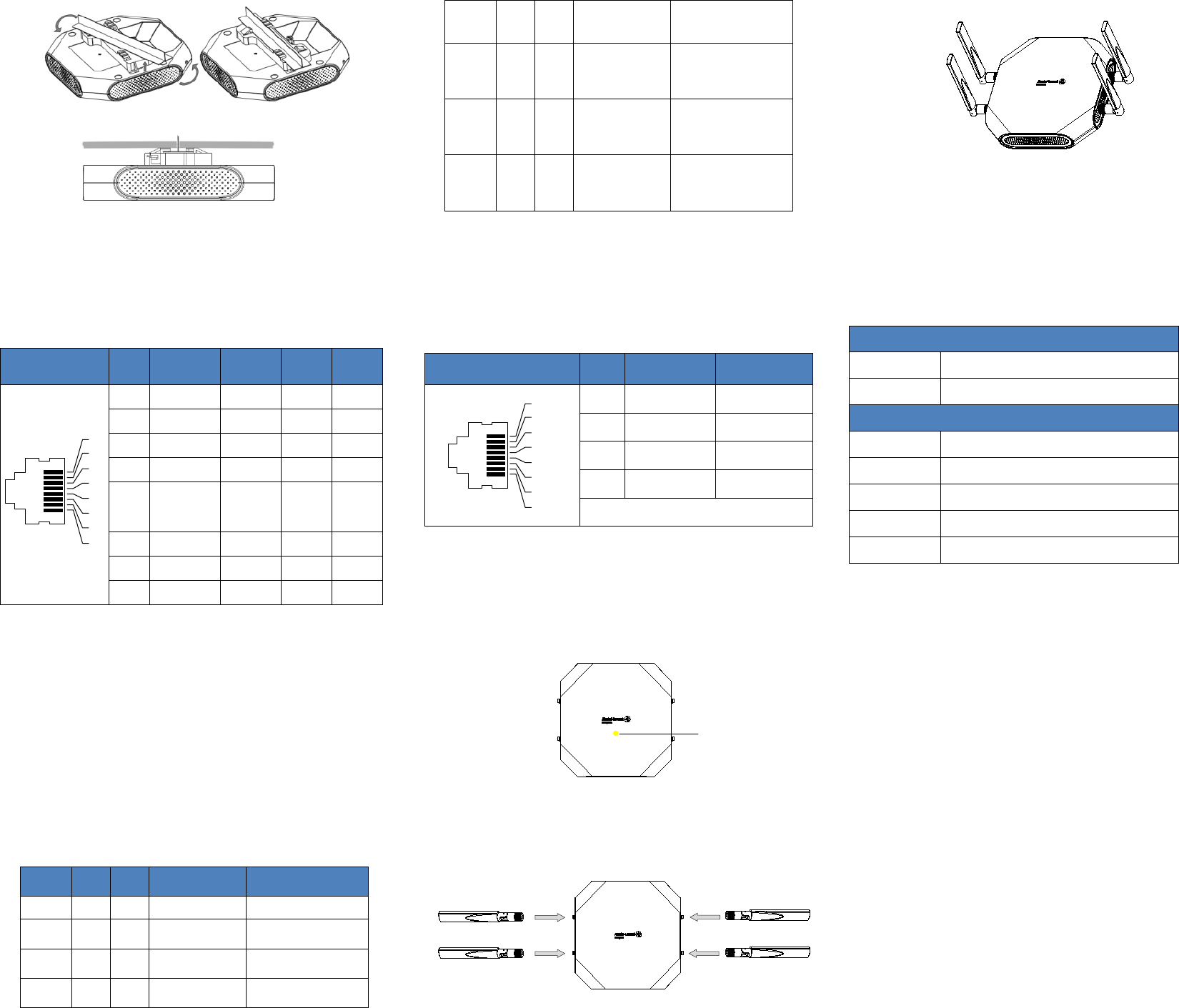
Figure 5: Mounting AP
Connect Ethernet
Use the Ethernet port to connect the AP with a twisted pair Ethernet LAN
segment. Use a 4- or 8-conductor, Category 5 UTP cable. The port is an
RJ-45 female connector with the pinouts shown in Ta b l e 2.
Connector Pin Signal
Name GE FE PoE
1
2
3
4
5
6
7
8
1 RJ45_DA+ BI_DA+ RX+ PoE-
2 RJ45_DA– BI_DA- RX– PoE-
3 RJ45_DB+ BI_DB+ TX+ PoE+
4 RJ45_DC+ BI_DC+ Spare PoE+
5 RJ45_DC– BI_DC-
BI_DA-
Spare PoE+
6 RJ45_DB– BI_DB- TX– PoE+
7 RJ45_DD+ BI_DD+ Spare PoE-
8 RJ45_DD– BI_DD- Spare PoE-
Tabl e 2: Ethernet Port Pinout
Connect Power Sources
Confirm that you have an IEEE 802.3at compliant Power over Ethernet
(PoE) source on the Ethernet cable, if not, connect by using the ALE 48V
AC-DC adapter kit (sold separately) to the DC Power Socket and AC power
jack.
If both PoE and DC power are available, the use of DC is preferred.
OmniAccess Stellar AP supports the power adapter provided by
ALE ONLY.
Verifying Post-Installation Connectivity
The LED on the AP can be used at this point to verify that the AP is
receiving power and initializing successfully (see Table 3).
Red
Blue
Green
Time
Line
Status
ON
Power
on
ON
Bootloader-OS
loading
System start up
Flash
System
running
Network abnormal
(Interface down)
Flash
System
running
Network normal,
without SSID created
ON
System
running
Network normal, single
band working,
either 2.4Ghz or 5Ghz
ON
System
running
Network normal, dual
bands working, 2.4Ghz
and 5Ghz are both
working
Flash
Flash
System
running
Red and Blue LEDs
alternate flashing
in specific frequency;
OS upgrading
Flash
Flash
Flash
System
running
3 LEDs alternate flash-
ing in specific
frequency; Used for
locating an AP
Tabl e 3: OmniAccess Stellar AP LED Meaning
Console Port
The serial console port allows you to connect the AP to a serial terminal
or a laptop for direct local management. This port is an RJ-45 female
connector with the pinouts described in Table 4.
Note: Currently for use by Service & Support only.
Connector Pin Signal Name Function
1
2
3
4
5
6
7
8
3 TXD Transmit
4 GND Ground
5 GND Ground
6 RXD Receive
Pins not listed are not connected.
Table 4: Console Port Pinout
Configuring the OmniAccess Stellar AP
Refer to the Quick Start Guide and Configuration Guide for complete
details.
OAW-AP1222 View
Figure 6
It is installed in the same way as OAW-AP1221. After the installation is
complete, install the external antenna on OAW-AP1222 (see figure 7).
Install the antenna as the figure 8:
Figure7
Figure 8
The external antenna is sold separately.
Contacting Alcatel-Lucent Enterprise
Website Support
Main Site http://enterprise.alcatel-lucent.com
Support Site http://support.esd.alcatel-lucent.com
Telephone Support
North America 1-800-995-2696
Latin America 1-877-919-9526
Europe +800 00200100 (Toll Free) or +1(650)385-2193
Asia Pacific +65 6240 8484
Other Region 1-818-878-4507
[REMAINING SECTIONS INTENTIONALLY LEFT BLANK]
Hidden LED Location