ALE 8379 DECT base station User Manual IBS 8379 for installation
ALE International DECT base station IBS 8379 for installation
ALE >
Contents
- 1. User Manual
- 2. Safety and regulatroy instructions
User Manual
OD-401366
V.2.2
IBS 8379 User Manual for installation
Uffoltz Pierre
Draft– 11/04/2018
3BN77020xxxx
1/26
Copyright © 2018 ALE International
IBS 8379 User Manual for installation
Approval Date: 11/04/2018 State:Draft
Approver: Guntzburger Philippe
OneDoc site: Hardware Product: 8379
Document Type: Installation_guide
Description: As user documentation is not available yet, this document gathers information’s to present the
IBS 8379 products, and their configuration
Keywords: DECT; IBS
History :
Edition
Date
Modification
Reason
00
05.04.2018
creation
01
09.04.2018
One Doc edition
02
11.04.2018
One Doc edition
Update after revue with SW
03
04.05.2018
One Doc edition
Title: remove R&D
Replace customer by installer
Remove 4.2.1 Antenna configuration
Remove all mention to TBR6, antenna
selection, reset button.
Remove mention for lab test to keep
IBS supply floating
Remove chapter 4.7.2.1 related to
R&D tests, and replace by the dip
switch configuration table
Remove R&D information, and keep
what is intended to be used in
customer doc.

OD-401366
V.2.2
IBS 8379 User Manual for installation
Uffoltz Pierre
Draft– 11/04/2018
3BN77020xxxx
2/26
Copyright © 2018 ALE International
Table of Contents
1. Terminology and Abbreviations ................................................................................................................ 3
2. Introduction ............................................................................................................................................... 3
3. Client information...................................................................................................................................... 4
4. Product description ................................................................................................................................... 5
4.1 Electrical description ......................................................................................................................... 5
4.1.1 Overall Block diagram ................................................................................................................ 7
4.2 PCB/PBA description .......................................................................................................................... 8
4.3 Mechanical description ..................................................................................................................... 8
4.4 Internal interfaces ............................................................................................................................. 9
4.5 External interfaces ........................................................................................................................... 10
4.6 Product Environment ...................................................................................................................... 10
4.6.1 Supplies .................................................................................................................................... 10
4.6.2 Overall environment diagram: ................................................................................................ 11
4.7 Product configuration ...................................................................................................................... 12
4.7.1 Nominal configuration ............................................................................................................. 12
4.7.2 Manual configuration .............................................................................................................. 16
5. Submitted Items lists ............................................................................................................................... 17
5.1 Test Items ........................................................................................................................................ 17
5.2 Accessories ...................................................................................................................................... 17
5.2.1 Power adapter: ........................................................................................................................ 17
5.2.2 Embedded antennas: ............................................................................................................... 17
5.2.3 External antennas: ................................................................................................................... 18
6. Annexes ................................................................................................................................................... 19
6.1 Products Photo ................................................................................................................................ 19
6.1.1 3BN77020BA 8379 DECT IBS INTEGRATEDANTENNAS ............................................................ 19
6.1.2 3BN77020CA 8379 DECT IBS FOR EXTERNAL ANTENNAS ........................................................ 20
6.1.3 3BN77020DA 8379 DECT IBS OUTDOOR EXTERNAL ANTENNAS ............................................. 21
6.2 Antenna specs ................................................................................................................................. 22
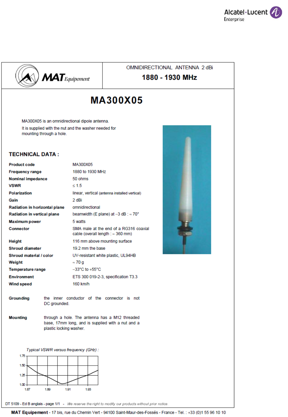
6.2.1 MA300x05 ................................................................................................................................ 22
6.2.2 MA430x12 ................................................................................................................................ 23
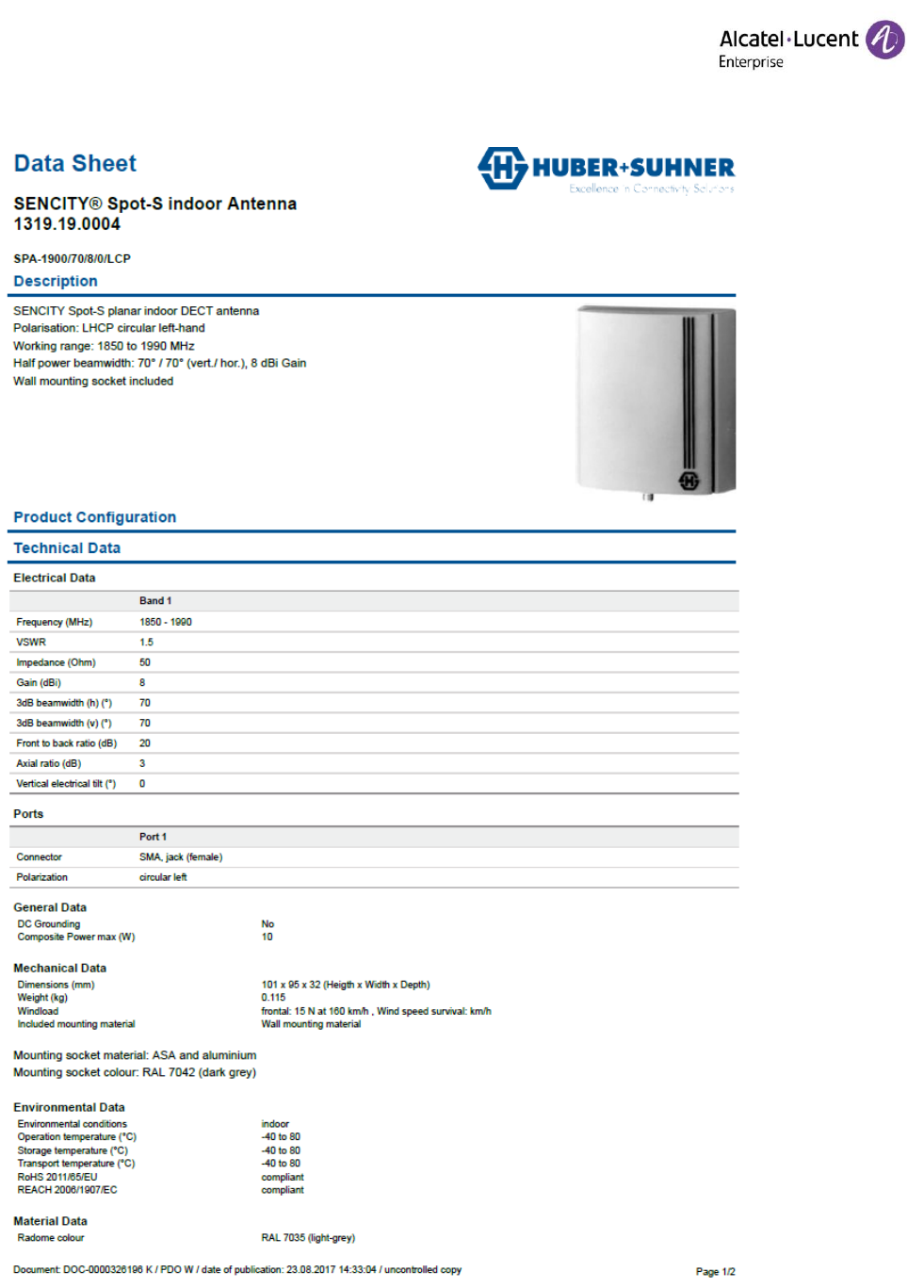
6.2.3 1319.19.0004 ........................................................................................................................... 24
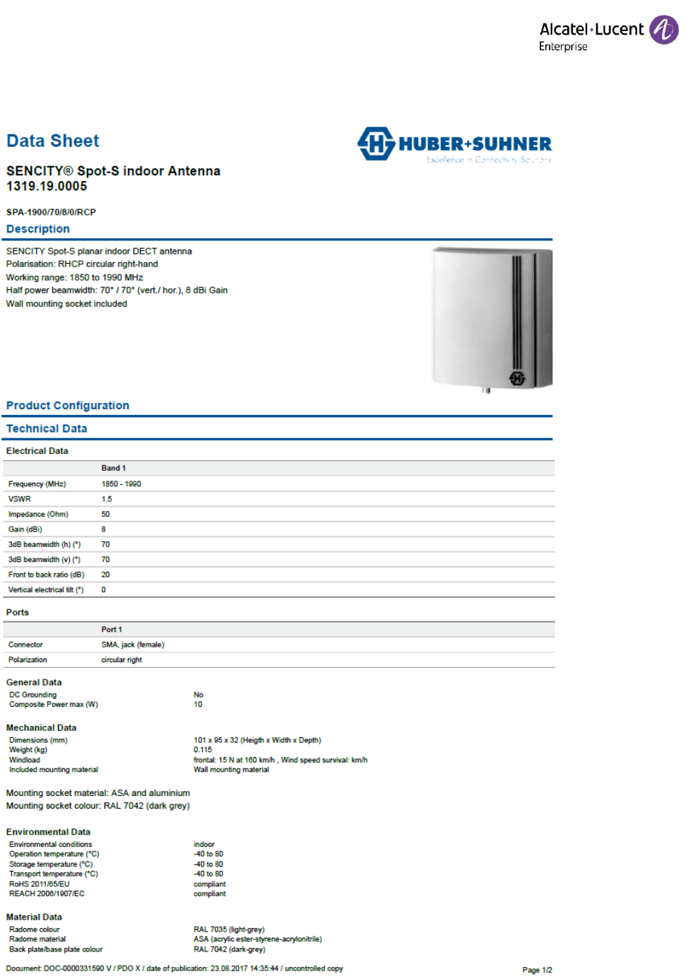
6.2.4 1319.19.0005 ........................................................................................................................... 25

OD-401366
V.2.2
IBS 8379 User Manual for installation
Uffoltz Pierre
Draft– 11/04/2018
3BN77020xxxx
3/26
Copyright © 2018 ALE International
1. Terminology and Abbreviations
AE Auxiliary Equipment
CE Conducted Emission
CS Conducted Susceptibility/Immunity
EFT/B Fast Transients / Bursts
EMC Electro Magnetic Compatibility
EMI Electro Magnetic interference
ESD Electrostatic discharge
EUT Equipment Under Test
IBS Intelligent Base Station
MFS Magnetic field strength
N.A. Not applicable
PABX Private Automatic Branch Exchange
PBA Printed Board Assembly
PoE Power Over Ethernet
RE Radiated Emission
RS Radiated Susceptibility/Immunity
2. Introduction
As user documentation is not available yet, this document gathers, information’s to present the product,
and his configuration. Official documentation for installation will be released with the Product Commercial
Release.

OD-401366
V.2.2
IBS 8379 User Manual for installation
Uffoltz Pierre
Draft– 11/04/2018
3BN77020xxxx
4/26
Copyright © 2018 ALE International
3. Client information
Name and address of the applicant:
ALE INTERNATIONAL
32 avenue Kléber
92700 Colombes
France
Name of contact person:
Patrick Hauptmann
+33 3 90 67 52 12
Name and address of manufacturer:
ALE INTERNATIONAL
32 avenue Kléber
92700 Colombes
France
Name and address of EMS:
ACCTON TECHNOLOGY CORPORATION INTERNATIONAL HQ
No 1 Creation 3rd RD
Science-Based Industrial Park
300077 HSINCHU CITY
TAIWAN R.O.C
Name and address of the factory:
JOY TECHNOLOGY (SHENZHEN) CO., LTD.
TongFuyu Ind., Shangpai, Shangwu,Aiqun Rd., Shiyan
Town, Shenzhen 518108 China
Tel:86-755-33816888
Product type:
Intelligent Base Station DECT
Trademarks:
Alcatel-Lucent
Models:
8379 DECT IBS INTEGRATED ANTENNAS
8379 DECT IBS FOR EXTERNAL ANTENNAS
8379 DECT IBS OUTDOOR EXTERNAL ANTENNAS
Accessories:
External antennas
Main power supply

OD-401366
V.2.2
IBS 8379 User Manual for installation
Uffoltz Pierre
Draft– 11/04/2018
3BN77020xxxx
5/26
Copyright © 2018 ALE International
4. Product description
IBS 8379 is an evolution of IBS 4070 made necessary by the obsolescence of:
the RF transceiver
the power supply controller.
IBS 8379 is 100% compatible with the existing IBS 4070 (i.e. installer can add an IBS 8379 to an existing
installation or replace an IBS 4070 with an IBS 8379 without any modification of the installation)
4.1 Electrical description
Main changes in IBS 8379 are:
The DE19RF19Z transceiver from DSPG Group replaces the Philips based RF module of IBS4070.
A mono board PCB architecture is used since this new radio uses much less components. As a
drawback, we have no more place to equip RBS components on the PCB.
Only IBS is considered by this product, RBS will remain a variant of 4070 design.
A small CPLD is used to adapt our ASIC BBIBS to the new radio interface of DSPG chip.
The power supply controller is modified but keeps the same external behavior (no input-output
isolation, same alarms, …). IBS 8379 is supplied:
o By PBX thanks to UA Links (remote supply)
o By external Main adapter. (see table at the end of this chapter)
The PCB supports two antenna designs:
o one with a printed antenna + wire antenna,
o and one with the same SMA than current IBS 4070 allowing the customer to use external
antenna.
SMA solution also remains a backup solution in case the printed antenna in not working as
expected.
Country/Region and Frequency range management:
o Thanks to the new DSPG chipset, all frequency range are covered with the same design.
There is no more need for Country/Region specific variants, IBS 8379 has worldwide
coverage.
o With a minor software evolution, the PABX will indicate to IBS 8379 which regional
setting it shall use. However, a default region is being configured in IBS Renewal for
compatibility with existing systems.
o To support old system without changing the PABX SW release, Installer is able to force
manually the region thanks to an internal HW switch (4xDIL).
OD-401366
V.2.2
IBS 8379 User Manual for installation
Uffoltz Pierre
Draft– 11/04/2018
3BN77020xxxx
6/26
Copyright © 2018 ALE International
DECT Europe spec:
DECT (Europe)
8379 DECT IBS
INTEGRATED ANTENNAS
8379 DECT IBS FOR
EXTERNAL ANTENNAS
8379 DECT IBS
OUTDOOR EXTERNAL
ANTENNAS
Technology:
DECT
Frequency band:
1880 – 1900MHz
Lowest transmit/receive
frequency/MHz:
1881,792 MHz
Highest transmit/receive
frequency/MHz:
1897,344 MHz
Kind of modulation:
GFSK
Test channel low:
9
Test channel middle:
5
Test channel high:
0
Maximum number of
timeslots:
12
12
12
Maximum number of
active timeslots:
6
6
6
Nominal peak output
power:
24 dBm/250mW
Averaged output power:
10,4mW/slot
DECT US spec:
For US configuration, the nominal peak output power is lowered to fulfill FCC regulation. Therefor
the output peak power is tuned below 20.88 dBm.
WA-13B48RG-BAAA (level VI) External Power supply spec:
Item
Performance
Remarks
Alcatel Part Number
3MG27066AABA
Output Voltage
48Vdc
Output Range
± 5%
Full Load
0.27A
Min. Load
0.0A
Max. Ripple
Voltage 300mVp-p
@Ta=25°C
Hold Up Time
10mS Min
Full Load & 110Vac/60Hz Input @Ta=25°C
Turn on Time
3 S Max
Full Load & 115Vac/60Hz Input @Ta=25°C
Overshoot
10% Max
Power on @90~264Vac/47~63Hz
Line regulation
± 1 %
Load regulation
± 5 %
OD-401366
V.2.2
IBS 8379 User Manual for installation
Uffoltz Pierre
Draft– 11/04/2018
3BN77020xxxx
7/26
Copyright © 2018 ALE International
4.1.1 Overall Block diagram
SW :
Boot
Start
application
BBIBS
DC/DC
48V to 3V4
1V8 LDO
Mains
Addapter
UA Connector
EMC
Prot.
EMC
Prot.
Line
i/f
Line
i/f
13.824M
Hz
XTAL
Reset
SRAM
NOR
FLASH
CPLD
RF
Transceiver
DSP
J
T
A
G
J
T
A
G
J
T
A
G
Region
Config
TBR6
TBR10
Uart
(3V3)
Unprot.
CODEC
LED
A4V A3V3 A1V8
I2C
16bit BUS
SPI bus
TRDATA
TXDATA
RXDATA
TDM
DSPCLK
RESET_DSP
HPI control
RFCLK
RESET_RF
RESET CPLD
SLOT_CTL &
RADIOEN
S
M
A
S
M
A
solder
solder
New design
OD-401366
V.2.2
IBS 8379 User Manual for installation
Uffoltz Pierre
Draft– 11/04/2018
3BN77020xxxx
8/26
Copyright © 2018 ALE International
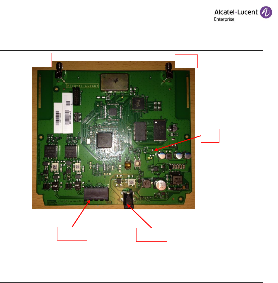
4.2 PCB/PBA description
The PCB has a global thickness of 1.6mm / FR4 material / controlled impedances: 50 Ω +/- 10%.
There are 3 PBA variants:
1. Indoor variant with SMA connectors. (to use external antennas)
2. Outdoor variant with SMA connectors (= indoor SMA PBA variant + tropicalized).
3. Indoor variant with integrated antenna:
The 2 antennas use soldered wires or ribbons which extend from the PCB.
A small modification of the indoor box is required to allow the mounting of these antenna
From electrical point of view, 1) & 2) are identical PBA (same components equipment). But reference
changes because of topicalization.
PBA
8379 DECT IBS
INTEGRATED ANTENNAS
8379 DECT IBS FOR
EXTERNAL ANTENNAS
8379 DECT IBS OUTDOOR
EXTERNAL ANTENNAS
Equipment
Equipped w/o SMA
Equipped w/ SMA
Antennas connection
Soldered
SMA connector
Antennas
Wired antenna (internal)
not delivered
external antenna 2dBi
embedded
External antenna
compatibility
NO
Yes
Yes
Tropicalisation
No
Yes
4.3 Mechanical description
The new board fits in the same boxes as the former product indoor & outdoor.
The PCB has the same size as IBS 4070
IBS Box modifications:
Minor mechanical changes of the indoor box are required for compatibility with the integrated
antenna. (remove some internal ribs)
Minor change in outdoor box on the Adaptation sheet : top-left hole fixation move
From external point of view, the new IBS 8379 has exactly the same look & feel than the previous IBS 4070.
We have total compatibility of the mounting of the new IBS to replace 4070 IBS.
OD-401366
V.2.2
IBS 8379 User Manual for installation
Uffoltz Pierre
Draft– 11/04/2018
3BN77020xxxx
9/26
Copyright © 2018 ALE International
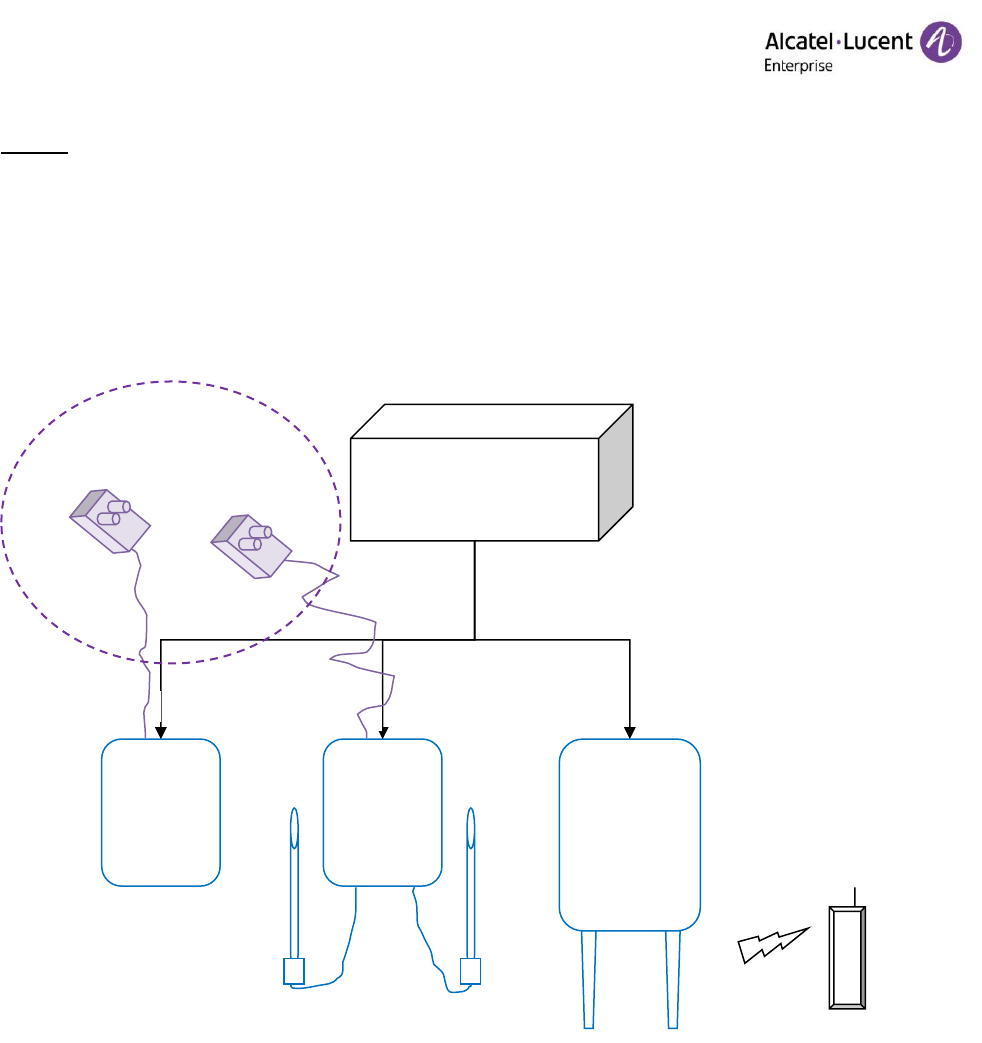
4.4 Internal interfaces
Board connections are shown here:
• The reset is done remotely by the PBX:
o SW reset = PBX message
o HW reset = PBX cut the UA power link
LED
AC Main
PBX link
Ant 1
Ant 2
OD-401366
V.2.2
IBS 8379 User Manual for installation
Uffoltz Pierre
Draft– 11/04/2018
3BN77020xxxx
10/26
Copyright © 2018 ALE International
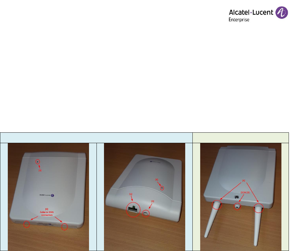
4.5 External interfaces
Product Interface one can access are:
1. UA0 & UA1 4x 5.08mm connector for UA cable.
2. External Main adapter. 2.0mm Jack Plug
3. LED provides visual indication
4. Antennas connected to SMA mounted on the PCB
Indoor
Outdoor
4.6 Product Environment
IBS 8379 shall be plugged as replacement of former IBS generation.
The configuration supports up to 2 UA link between THE PABX and the IBS.
Each UA link provides 256kBits full duplex data rate:
1x64kbit signalization
6x32kbit ADPCM
ADPCM/PCM transcoding is done in the PABX.
4.6.1 Supplies
The IBS 8379 is powered like former base station generation. The supply can be:
• Remote supply for all base stations variant
• AC main adapter for indoor product only.
OD-401366
V.2.2
IBS 8379 User Manual for installation
Uffoltz Pierre
Draft– 11/04/2018
3BN77020xxxx
11/26
Copyright © 2018 ALE International
Note 1:
Even if we plug the AC Main, PBX link must be plugged to enable the base station.
4.6.2 Overall environment diagram:
PABX
IBS 8379
Indoor
(int.
antenna)
IBS 8379
Indoor
(Ext.
antenna)
IBS 8379
Outdoor
UA x1..x2
UA x1..x2
UA x1..x2
UA x3..x6
DECT handset
Optional
Main addapter

OD-401366
V.2.2
IBS 8379 User Manual for installation
Uffoltz Pierre
Draft– 11/04/2018
3BN77020xxxx
12/26
Copyright © 2018 ALE International
4.7 Product configuration
4.7.1 Nominal configuration
In normal use, the configuration of the IBS is the default one (out of the box).
The Base station starts without activating RF, and wait PBX connection through the UA link.
Important:
• The end user has no way to change the frequency or output power of the base station.
• Only the installer can manage the RF Frequency Band and/or the output power. Either in the PBX
configuration, protected by password, either on the HW dip switch inside the box and not available
as external interface.
• Installer must ensure the configuration he chooses, complies with local regulation. And installer
must ensure to avoid un-authorized configuration setting.
Several cases are possible:
IBS 8379 is connected to new PBX release (i.e. OXE R12.2 or above):
o At initialization, the PBX will send the frequency band to the IBS.
o IBS will configure his RF chip for DECT in the correct frequency band
IBS 8379 is connected to older PBX release:
o At initialization, the PBX does not give the frequency band info.
o IBS will send back her current frequency band (ex. European)
o The PBX checks the IBS region
▪ If IBS region is compatible with PBX configured region
then all is OK, base station is operating
▪ Else IBS region is not compatible with the PBX configured region
Then the PBX resets the IBS
o IBS restarts, and again receive the PBX init message without frequency band info.
o This time IBS will send back a status with the next frequency band in the list (ex. China)
o This process will loop over the 4 frequency bands (Europe – China – Latam - US) until the PBX
and the IBS region are compatible. Then the base station is working.
Installer wants to force in manual mode the IBS region:
o Installer opens the base station shell, select the relevant value
o When connected to the system, the IBS will start with the region set.
o When the OXE checks the region compatibility, he resets the base station if not compatible.
o It is then under installer responsibility to configure correctly the base station.
OD-401366
V.2.2
IBS 8379 User Manual for installation
Uffoltz Pierre
Draft– 11/04/2018
3BN77020xxxx
13/26
Copyright © 2018 ALE International
The SW knows the IBS variant (indoor, indoor with ext. antenna, outdoor) from ALE part number stored in
EEPROM during manufacturing tests.
Therefor the output power can be reduced automatically for indoor product according the next table.
But the outdoor product has one case involving manual setting (represented in blue). This case is used when
the installer will connect 8dBi antenna on outdoor product in US frequency band.
IBS 8379 IO INDOOR
INTEGRATED ANTENNAS
IBS 8379 IO INDOOR FOR
EXTERNAL ANTENNAS
IBS 8379 EO OUTDOOR
WITH EXT. ANTENNAS
DIP
switch 4
Region
3BN73020BA..
3BN73020CA..
3BN73020DA..
RFBD-4
Europe
23dBm
23dBm
23dBm
1
China
23dBm
23dBm
23dBm
1
Latam
23dBm
23dBm
23dBm
1
USA
19dBm
13dBm
19dBm
1
USA
13dBm
13dBm
13dBm
0
Note 1: The Bold value in the table represent the physical configuration of IBS Base station with external
antenna of 8dBi gain
Note 2: Even if not mandatory, region like Europe can be configured by installer with the output power
reduced by 6dB. This could help if there are too much reflection in a given location, or if several Base stations
are in a close location to increase density.
OD-401366
V.2.2
IBS 8379 User Manual for installation
Uffoltz Pierre
Draft– 11/04/2018
3BN77020xxxx
14/26
Copyright © 2018 ALE International
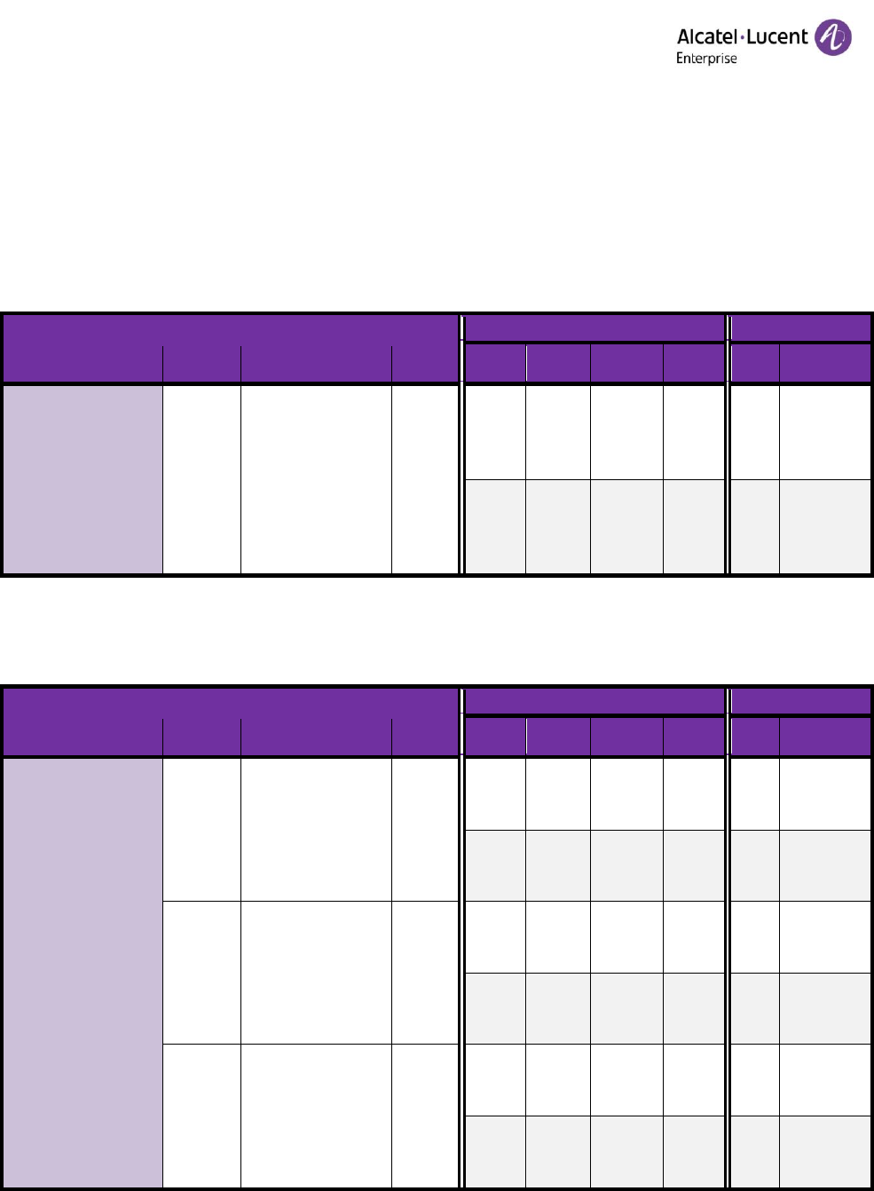
4.7.1.1 Compatibility table
Compatibility table is shown hereafter:
- Standard use in Bold
- Reduced power in grey
4.7.1.1.1 8379 DECT IBS INTEGRATED ANTENNAS: 3BN77020BA
Other
countries
US
Only
Product
Antenna
Antenna ref
Antenna
Gain
Europe
China
Latam
USA
8379 DECT IBS
INTEGRATED ANTENNAS
3BN77020BA
Integrated
None, wire + printed
PCB
2dB omnidirectional
2dBi
23dBm
23dBm
23dBm
19dBm
17dBm
17dBm
17dBm
13dBm
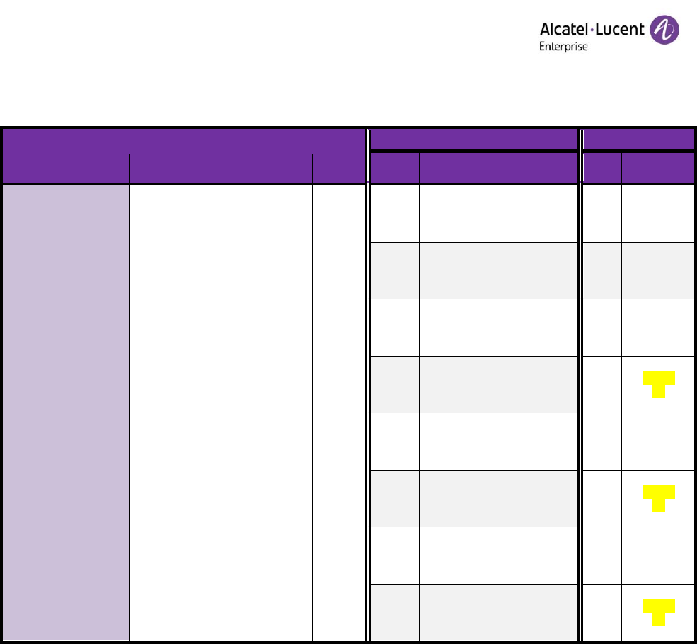
4.7.1.1.2 8379 DECT IBS FOR EXTERNAL ANTENNAS: 3BN77020CA
Other
countries
US
Only
Product
Antenna
Antenna ref
Antenna
Gain
Europe
China
Latam
USA
8379 DECT IBS FOR
EXTERNAL ANTENNAS
3BN77020CA
External
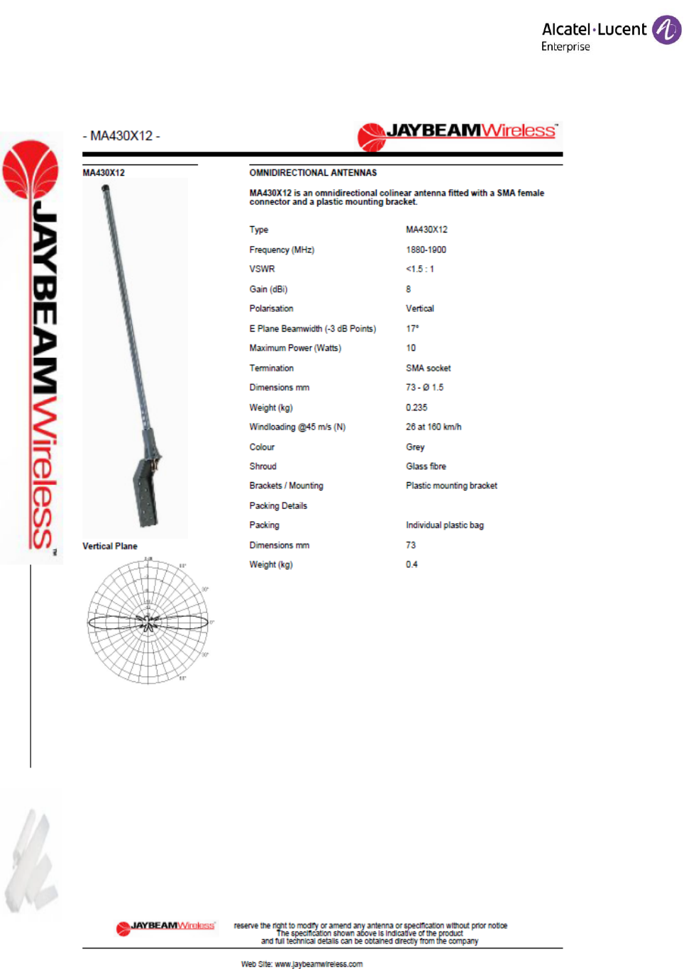
MA430X12
7.5dB omnidirectional
8dBi
23dBm
23dBm
23dBm
13dBm
17dBm
17dBm
17dBm
13dBm
External
1319.19.0004
LHCP circular righthand
8dBi
23dBm
23dBm
23dBm
13dBm
17dBm
17dBm
17dBm
13dBm
External
1319.19.0005
RHCP circular righthand
8dBi
23dBm
23dBm
23dBm
13dBm
17dBm
17dBm
17dBm
13dBm
OD-401366
V.2.2
IBS 8379 User Manual for installation
Uffoltz Pierre
Draft– 11/04/2018
3BN77020xxxx
15/26
Copyright © 2018 ALE International
4.7.1.1.3 8379 DECT IBS OUTDOOR EXTERNAL ANTENNAS: 3BN77020DA
Other
countries
US
Only
Product
Antenna
Antenna ref
Antenna
Gain
Europe
China
Latam
USA
8379 DECT IBS OUTDOOR
EXTERNAL ANTENNAS
3BN77020DA
External
MA300X05
2dB omnidirectional
2dBi
23dBm
23dBm
23dBm
19dBm
17dBm
17dBm
17dBm
13dBm
External
MA430X12
7.5dB omnidirectional
8dBi
23dBm
23dBm
23dBm
Unauthorized
(1)
17dBm
17dBm
17dBm
13dBm
(2)
External
1319.19.0004
LHCP circular righthand
8dBi
23dBm
23dBm
23dBm
Unauthorized
(1)
17dBm
17dBm
17dBm
13dBm
(2)
External
1319.19.0005
RHCP circular righthand
8dBi
23dBm
23dBm
23dBm
Unauthorized
(1)
17dBm
17dBm
17dBm
13dBm
(2)
Note 1: Unauthorized configuration. Installer needs to take care to never use this setting. Installer must follow
the expert configuration documentations.
Note 2: Underlined in yellow, requested configuration. Installer must follow the expert configuration
documentations.

OD-401366
V.2.2
IBS 8379 User Manual for installation
Uffoltz Pierre
Draft– 11/04/2018
3BN77020xxxx
16/26
Copyright © 2018 ALE International
4.7.2 Manual configuration
Nominal case does not require to do manual configuration. The SW can configure dynamically the 8379 DECT
Base Station.
End user has not access to Manual configuration.
Installer must follow the expert configuration documentations, to configure correctly and homogenously the
whole system.
OD-401366
V.2.2
IBS 8379 User Manual for installation
Uffoltz Pierre
Draft– 11/04/2018
3BN77020xxxx
17/26
Copyright © 2018 ALE International
5. Submitted Items lists
5.1 Test Items
Ref
Commercial
3BN77020BA
8379 DECT IBS INTEGRATED ANTENNAS
3BN77020CA
8379 DECT IBS FOR EXTERNAL ANTENNAS
3BN77020DA
8379 DECT IBS OUTDOOR EXTERNAL ANTENNAS
5.2 Accessories
5.2.1 Power adapter:
ref
Commercial
3MG27066AABA
WA-13B48RG-BAAA
(level VI)
Power Adapter with movable plug
Input:90-264V,47~63Hz
Output:48V/0.27A
5.2.2 Embedded antennas:
Antenna integrated on the IBS 8379 indoor: 3BN77020BA
ref
Commercial
None, wire + printed PCB
2dB omnidirectional
Gain 2dBi
Antenna embedded on the IBS 8379 outdoor: 3BN77020DA
ref
Commercial
1AF10050AAAA
MA300X05
2dB omnidirectional

OD-401366
V.2.2
IBS 8379 User Manual for installation
Uffoltz Pierre
Draft– 11/04/2018
3BN77020xxxx
18/26
Copyright © 2018 ALE International
5.2.3 External antennas:
ref
Commercial
3BD52212AA
MA430X12
7.5dB omnidirectional
https://amphenol-antennas.com/
▪ Type MA430X12
▪ Frequency (MHz) 1880-1900
▪ VSWR <1.5 : 1
▪ Gain (dBi) 8
▪ Polarisation Vertical
▪ E Plane Beamwidth (-3 dB Points) 17°
▪ Maximum Power (Watts) 10
▪ Termination SMA socket
▪ Dimensions mm 73 - Ø 1.5
▪ Weight (kg) 0.235
▪ Windloading @45 m/s (N) 26 at 160 km/h
▪ Colour Grey
▪ Shroud Glass fibre
▪ Brackets / Mounting Plastic mounting
bracket
▪ Packing Details
▪ Packing Individual plastic bag
▪ Dimensions mm 73
▪ Weight (kg) 0.4
3BD52205AA
SENCITY® Spot-S indoor Antenna
https://ecatalog.hubersuhner.com
▪ 1319.19.0005
▪ item n° 22650451
▪ SENCITY SpotS planar indoor DECT
antenna
▪ Polarisation: RHCP circular righthand
▪ Working range: 1850 to 1990 MHz
▪ Half power beamwidth: 70° / 70° (vert./
hor.); 8 dBi Gain
▪ Wall mounting socket included
3BD52206AA
SENCITY® Spot-S indoor Antenna
https://ecatalog.hubersuhner.com
▪ 1319.19.0004
▪ item n° 22650455
▪ SENCITY SpotS planar indoor DECT
antenna
▪ Polarisation: LHCP circular lefthand
▪ Working range: 1850 to 1990 MHz
▪ Half power beamwidth: 70° / 70° (vert./
hor.); 8 dBi Gain
▪ Wall mounting socket included
3DC01001AA
DC Bloc
▪ SMA DC bloc
OD-401366
V.2.2
IBS 8379 User Manual for installation
Uffoltz Pierre
Draft– 11/04/2018
3BN77020xxxx
19/26
Copyright © 2018 ALE International
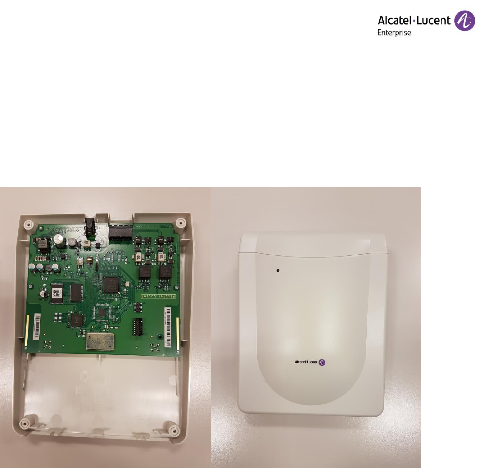
6. Annexes
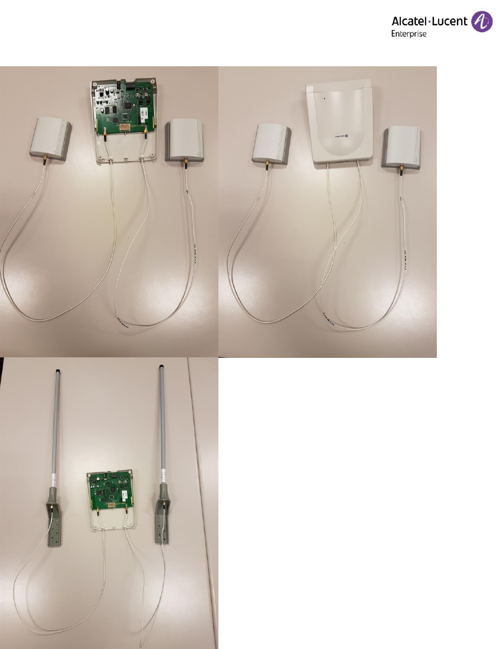
6.1 Products Photo
Hereafter you find a portfolio with some photo presenting the different IBS. Not all combination of external
antenna are presented, but at least one of each.
6.1.1 3BN77020BA 8379 DECT IBS INTEGRATEDANTENNAS
OD-401366
V.2.2
IBS 8379 User Manual for installation
Uffoltz Pierre
Draft– 11/04/2018
3BN77020xxxx
20/26
Copyright © 2018 ALE International
6.1.2 3BN77020CA 8379 DECT IBS FOR EXTERNAL ANTENNAS
OD-401366
V.2.2
IBS 8379 User Manual for installation
Uffoltz Pierre
Draft– 11/04/2018
3BN77020xxxx
21/26
Copyright © 2018 ALE International
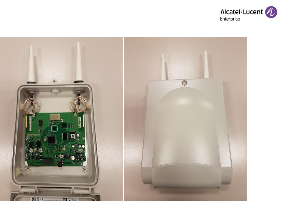
6.1.3 3BN77020DA 8379 DECT IBS OUTDOOR EXTERNAL ANTENNAS
OD-401366
V.2.2
IBS 8379 User Manual for installation
Uffoltz Pierre
Draft– 11/04/2018
3BN77020xxxx
22/26
Copyright © 2018 ALE International
6.2 Antenna specs
6.2.1 MA300x05
OD-401366
V.2.2
IBS 8379 User Manual for installation
Uffoltz Pierre
Draft– 11/04/2018
3BN77020xxxx
23/26
Copyright © 2018 ALE International
6.2.2 MA430x12
OD-401366
V.2.2
IBS 8379 User Manual for installation
Uffoltz Pierre
Draft– 11/04/2018
3BN77020xxxx
24/26
Copyright © 2018 ALE International
6.2.3 1319.19.0004
OD-401366
V.2.2
IBS 8379 User Manual for installation
Uffoltz Pierre
Draft– 11/04/2018
3BN77020xxxx
25/26
Copyright © 2018 ALE International
6.2.4 1319.19.0005
OD-401366
V.2.2
IBS 8379 User Manual for installation
Uffoltz Pierre
Draft– 11/04/2018
3BN77020xxxx
26/26
Copyright © 2016 ALE International
www.al-enterprise.com The Alcatel-Lucent name and logo are trademarks of Nokia used under license by
ALE. To view other trademarks used by affiliated companies of ALE Holding, visit:
www.al-enterprise.com/en/legal/trademarks-copyright. All other trademarks are the property of their
respective owners. The information presented is subject to change without notice. Neither ALE Holding nor
any of its affiliates assumes any responsibility for inaccuracies contained herein. © 2018 ALE International.
All rights reserved. MPR00042018
END OF DOCUMENT