ALPHATRON MARINE USA JMA-610 Marine Radar User Manual Part 2
ALPHATRON MARINE USA, INC. Marine Radar Part 2
Contents
- 1. User manual Part 2
- 2. User Manual Part 3
- 3. Updated Part 1 of user manual
User manual Part 2
SECTION 3
BASIC OPERATION
3.1 FLOW OPERATION.....................................................................................3-1
3.1.1 POWER ON AND START THE SYSTEM ....................................................3-2
3.1.2 OBSERVE AND ADJUST VIDEO................................................................3-3
3.1.3 ACQUIRE AND MEASURE DATA...............................................................3-3
3.1.4 END THE OPERATION AND STOP THE SYSTEM ....................................3-4
3.2 MENU COMPOSITION ................................................................................3-5
3.3 PREPARATION............................................................................................ 3-9
3.3.1 ADJUST DISPLAY BRILLIANCE [BRILL] ..................................................3-9
3.3.2 ADJUST OPERATION PANEL BRILLIANCE [PANEL] .............................. 3-9
3.3.3 SWITCH DAY/NIGHT MODE [DAY/NIGHT] ................................................3-9
3.3.4 ADJUST BRILLIANCE OF INFORMATION ON RADAR DISPLAY
(BRILLIANCE SETTING)........................................................................... 3-10
3.3.5 ADJUST SOUND VOLUME (BUZZER VOLUME).....................................3-10
3.3.6 RESET ALARM BUZZER [ALARM ACK] ................................................. 3-11
3.3.7 SET DISPLAY COLOR .............................................................................. 3-11
3.4 BASIC OPERATIONS................................................................................ 3-12
3.4.1 START TRANSMISSION [TX] ................................................................... 3-12
3.4.2 STOP TRANSMISSION [STBY] ................................................................ 3-12
3.4.3 CHANGE RANGE (OBSERVATION RANGE SCALE) [+RANGE-] .......... 3-13
3.4.4 TUNE .........................................................................................................3-13
3.4.5 CONTROL SENSITIVITY [GAIN] ..............................................................3-14
3.4.6 SUPPRESS SEA CLUTTER [SEA] ...........................................................3-14
3.4.7 SUPPRESS RAIN/SNOW CLUTTER [RAIN] ............................................ 3-15
3.4.8 REJECT RADAR INTERFERENCE [IR] ...................................................3-16
3.4.9 HIDE/DISPLAY RANGE RINGS (RINGS)..................................................3-16
3.4.10 HIDE SHIP’S HEADING LINE (HL OFF) ...................................................3-17
3.5 GENERAL OPERATIONS ......................................................................... 3-18
3.5.1 MOVE CROSS CURSOR MARK BY TRACKBALL..................................3-18
3.5.2 USE EBLS (ELECTRONIC BEARING LINES) [EBL1/EBL2] ................... 3-18
3.5.3 USE VRMS (VARIABLE RANGE MARKERS) [VRM1/VRM2]..................3-20
3.5.4 USE P-LINES (PARALLEL INDEX LINES) [P-LINE] ................................3-22
3.5.5 MOVE OWN SHIP’S DISPLAY POSITION [OFF CENT]........................... 3-23
3.5.6 DISPLAY OTHER SHIPS’ TRAILS [TRAILS]............................................3-23
3.5.7 DISPLAY OWN VECTOR [OWN VECT]....................................................3-25
3.5.8 EDITING OWN MARK ...............................................................................3-26
3.5.9 TIME ZONE SETTING ...............................................................................3-34
3.5.10 LOCAL TIME SETTING ............................................................................. 3-35
3.5.11 CHANGE THE UNIT OF RATE OF TURN ................................................. 3-36
3.5.12 DISPLAY AIS LABEL ................................................................................3-37
3.5.13 ECHO EXPANSION SWITCH .................................................................... 3-37
3.6 DISAPLAY USER MAP..............................................................................3-38
3.6.1 EDIT USER MAP .......................................................................................3-38
3.6.2 CORRECT POSITION ON USER MAP (SHIFT )....................................... 3-41
3.6.3 CORRECT POSITION ON USER MAP (SHIFT CLEAR). .........................3-41
3.6.4 SET USER MAP DISPLAY (MARK DISPLAY SETTING).......................... 3-42
3.6.5 OPERATE USER MAP FILE (FILE OPERATIONS) ..................................3-52
3.7 SCREEN CAPTURE .................................................................................. 3-63
3.7.1 SCREEN CAPTURE SETTING (SELECT CARD SLOT). .........................3-63
3.7.2 SCREEN CAPTURE SETTING (SAVE FILE). ........................................... 3-65
3.7.3 SCREEN CAPTURE SETTING (ERASE FILE). ........................................ 3-66
3.7.4 SCREEN CAPTURE SETTING (AUTO CAPTURE)..................................3-67
3.7.5 SCREEN CAPTURE SETTING (AUTO CAPTURE MODE). .....................3-68
3.7.6 SCREEN CAPTURE SETTING (AUTO CAPTURE INTERVAL). ..............3-69
3.7.7 SCREEN CAPTURE SETTING (AUTO FILE ERASE). ............................. 3-70
3.7.8 SCREEN CAPTURE SETTING (MANUAL CAPTURE)............................. 3-71
3.8 USER SETTING......................................................................................... 3-72
3.8.1 USER SETTING (LOAD USER SETTING)................................................ 3-72
3.8.2 USER SETTING (SAVE USER SETTING).................................................3-73
3.8.3 USER SETTING (ERASE USER SETTING)..............................................3-74
3.9 FORMAT CARD.........................................................................................3-75
3.9.1 FORMAT CARD (SELECT CARD SLOT)..................................................3-75
3.10 AIS FUNCTION.......................................................................................... 3-76
3.10.1 VESSEL NAME LIST.................................................................................3-76
3.10.2 VESSEL INFORMATION ...........................................................................3-76
3.10.3 DISPLAY THE VESSEL NAMES ON THE SCREEN................................. 3-77
3.10.4 AIS SETTING MENU .................................................................................3-77
3.10.5 AIS SYMBOL.............................................................................................3-78
3-1
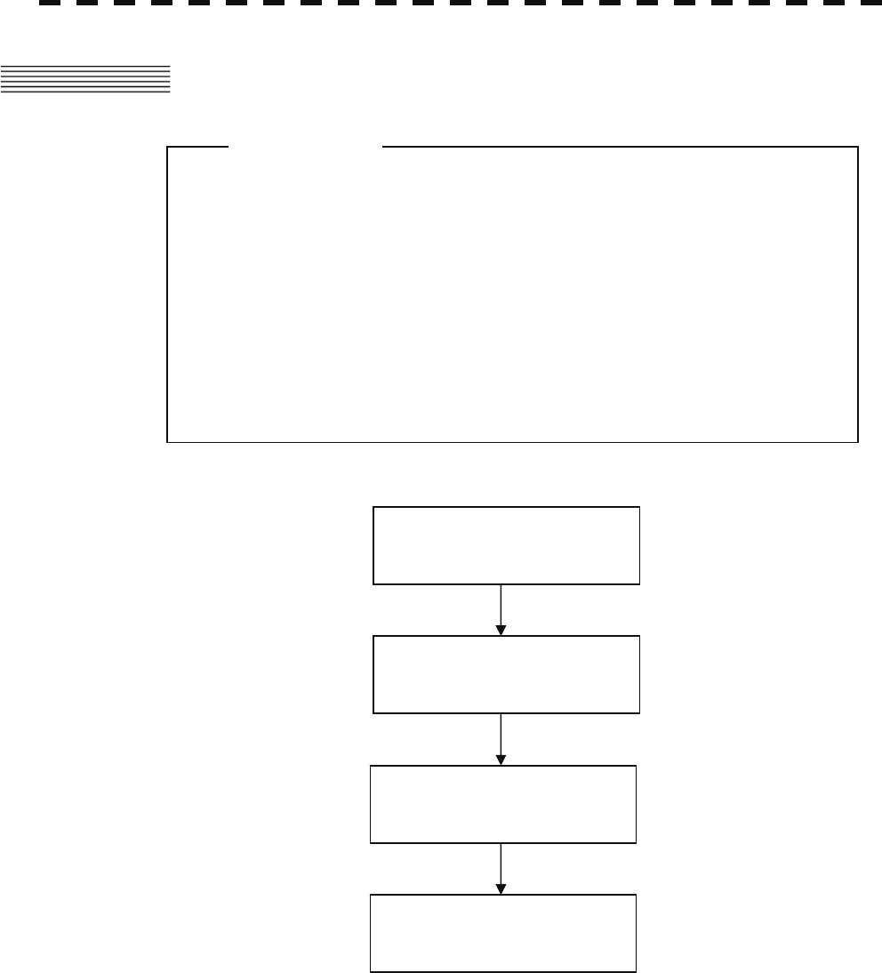
3.1 FLOW OPERATION
Each operation is described in detail below.
z Do not put anything on the operation panel.
If you put anything hot on it, it may be deformed.
z Do not give any impact to the operation panel,
trackball, or controls.
Otherwise, any failure or damage may result.
Attention
POWER ON AND
START THE SYSTEM
OBSERVE AND
ADJUST VIDEO
ACQUIRE AND
MEASURE DATA
END THE OPERATION AND
STOP THE SYSTEM
3-2
3
3.1 FLOW OPERATION y
y y
3.1.1 Power ON and Start the System
z Wait for about 2 seconds before turning on the
power again.
z Immediately after the radar is installed, at start of the
system after it has not been used for a long time, or
after the magnetron is replaced, preheat the
equipment in the standby state for 20 to 30 minutes
before setting it into the transmit state.
z If the preheating time is short, the magnetron
causes sparks, resulting in its unstable oscillation.
Start transmission on a short-pulse range and
change the range to the longer pulse ranges in turn.
If the transmission is unstable in the meantime,
immediately place the system back into the standby
state and maintain it in the standby state for 5 to 10
minutes before restarting the operation.
Repeat these steps until the operation is stabilized.
Attention
A malfunction may occur if the power in the
ship is instantaneously interrupted during
operation of the radar. In this case, the power
should be turned on again.
CAUTION
3-3
Procedures 1 Check that the ship’s mains are turned on.
2 Press [STBY] key.
The system is turned on, and the preheating time is displayed.
PREHEAT is indicated at the upper left of the radar display.
3 Wait until the preheating time is over.
When the preheating time is over, the preheating time screen disappears, and PREHEAT
at the upper left of the radar display changes to STANDBY .
4 Press [TX] key.
The radar will start transmission and the antenna will start rotating.
STANDBY at the upper left of the radar display changes to TRANSMIT .
Note: The radar does not start transmission if you press [TX] key while PREHEAT is indicated.
3.1.2 Observe and Adjust Video
Procedures 1 Press [+RANGE-] key to set the range to the scale required for target
observation.
2 Turn the controls [GAIN], [SEA], and [RAIN] to obtain the clearest
targets.
3.1.3 Acquire and Measure Data
For details on data acquisition and measurement, refer to Section 3.4 “BASIC OPERATIONS” and Section 4
“MEASUREMENT OF RANGE AND BEARING.”
3-4
3
3.1 FLOW OPERATION y
y y
3.1.4 End the Operation and Stop the System
Exit 1 Press [STBY] key.
The radar will stop transmission and the antenna will stop rotating.
TRANSMIT at the upper left of the radar display changes to STANDBY .
Maintain the standby state if radar observation is restarted in a relatively short time.
Only pressing the [TX] key starts observation.
2 Press the [STBY] key and the [TX] key together.
The system will be turned off.
When conducting maintenance work, make sure to turn
off the power and unplug the power line of the
processor so that the power supply to the equipment is
completely cut off.
Some equipment components can carry electrical
current even after the power switch is turned off, and
conducting maintenance work without unplugging the
power connector may result in electrocution,
equipment failure, or accidents.
WARNING
3-5
3.2 MENU COMPOSITION
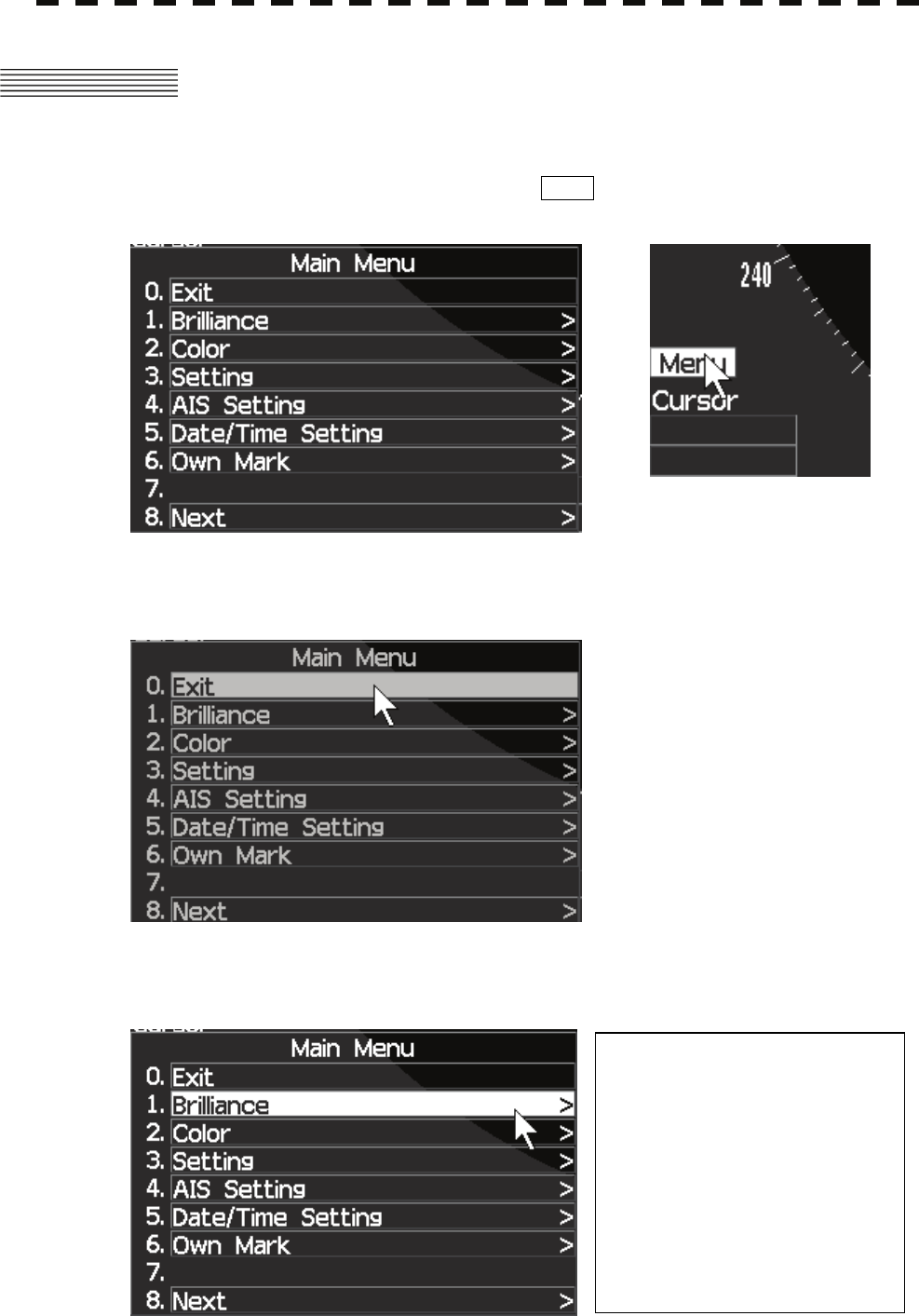
This radar has main menu as following.
Press [MENU] key on panel switch or select Menu icon with trackball and press
[ENTER] key.
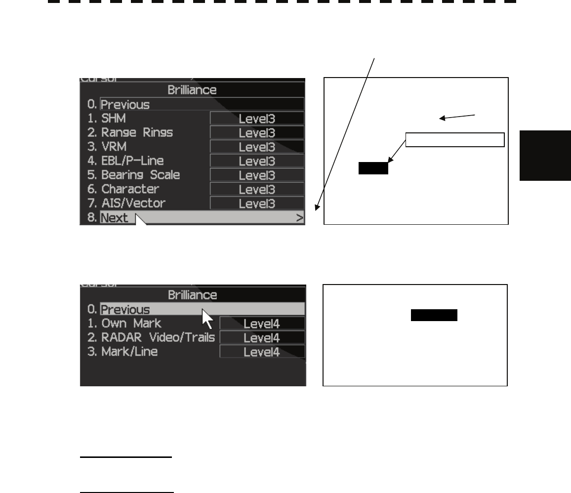
Select item with trackball and Press [ENTER] key.
Select item with trackball.
Monochrome reversed character
means selected item.
In this case, Brilliance control item
is selected.
3-6
3
3.2 MENU COMPOSITION y
y y
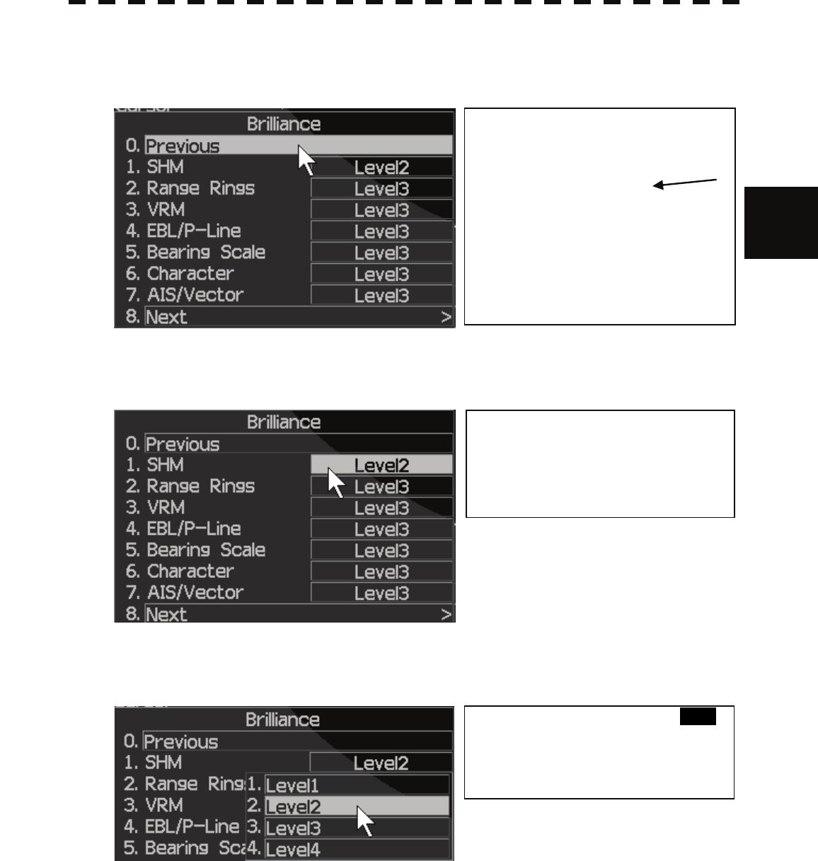
Select item with trackball.
Select item with trackball.
Select item with trackball and Press [ENTER] key.
Level selection menu.
Previously selected level
SHM Level2
Range Rings Level3
VRM Level3
EBL/P-Line Level3
Bearing Scale Level3
Character Level3
AIS/Vector Level3
Select SHM Level2
Cursor is on previously selected level2
3-7
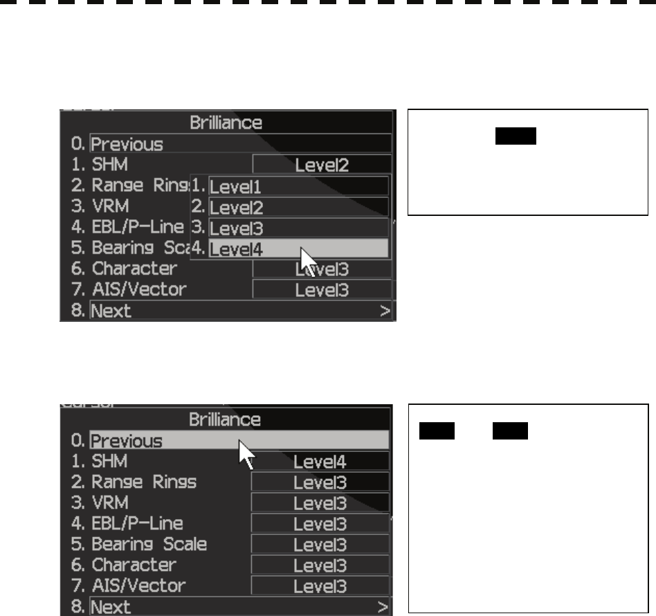
Select item with trackball.
Select item with trackball and Press [ENTER] key.
SHM Level setting sequence is finished.
Select next another item if want to change.
The same way ,possible to change follow items.
SHM /Range Rings /VRM/ EBL/P-Line/Bearing Scale/Character/AIS/Vector
/Own Mark/RADAR Video/Trails/Mark/Line.
SHM brilliance level is changed to
level4 from level2.
SHM Level4
Range Rings Level3
VRM Level3
EBL/P-Line Level3
Bearing Scale Level3
Character Level3
AIS/Vector Level3
Select Level which you need.
In this case, Level4 is chosen.
3-8
3
3.2 MENU COMPOSITION y
y y
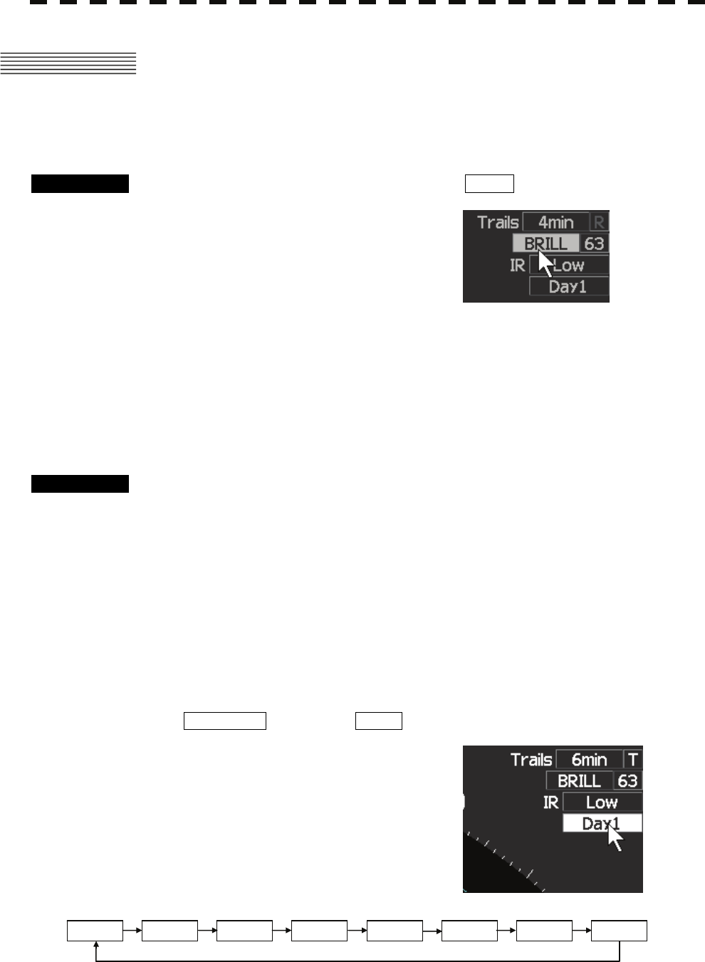
In case of Own Mark/RADAR Video/Trails/Mark/Line, select Next.
Select item with trackball and Press [ENTER] key.
Change level is possible in the same way as the above.
To open the menu:
Press [MENU] key.
To close the menu:
Press key [MENU] again
To determine the selected item:
Place the cursor over the selected item with trackball and then press [ENTER] key.
Level selection menu.
SHM Level2
1. Level1
2. Level2
3. Level3
4. Level4
Now, select Level4
Finish the SHM brilliance level
setting.
Menu is return to 0.Previous select.
Select next item which you want to
change.
3-9
3.3 PREPARATION
3.3.1 Adjust Display Brilliance [BRILL]
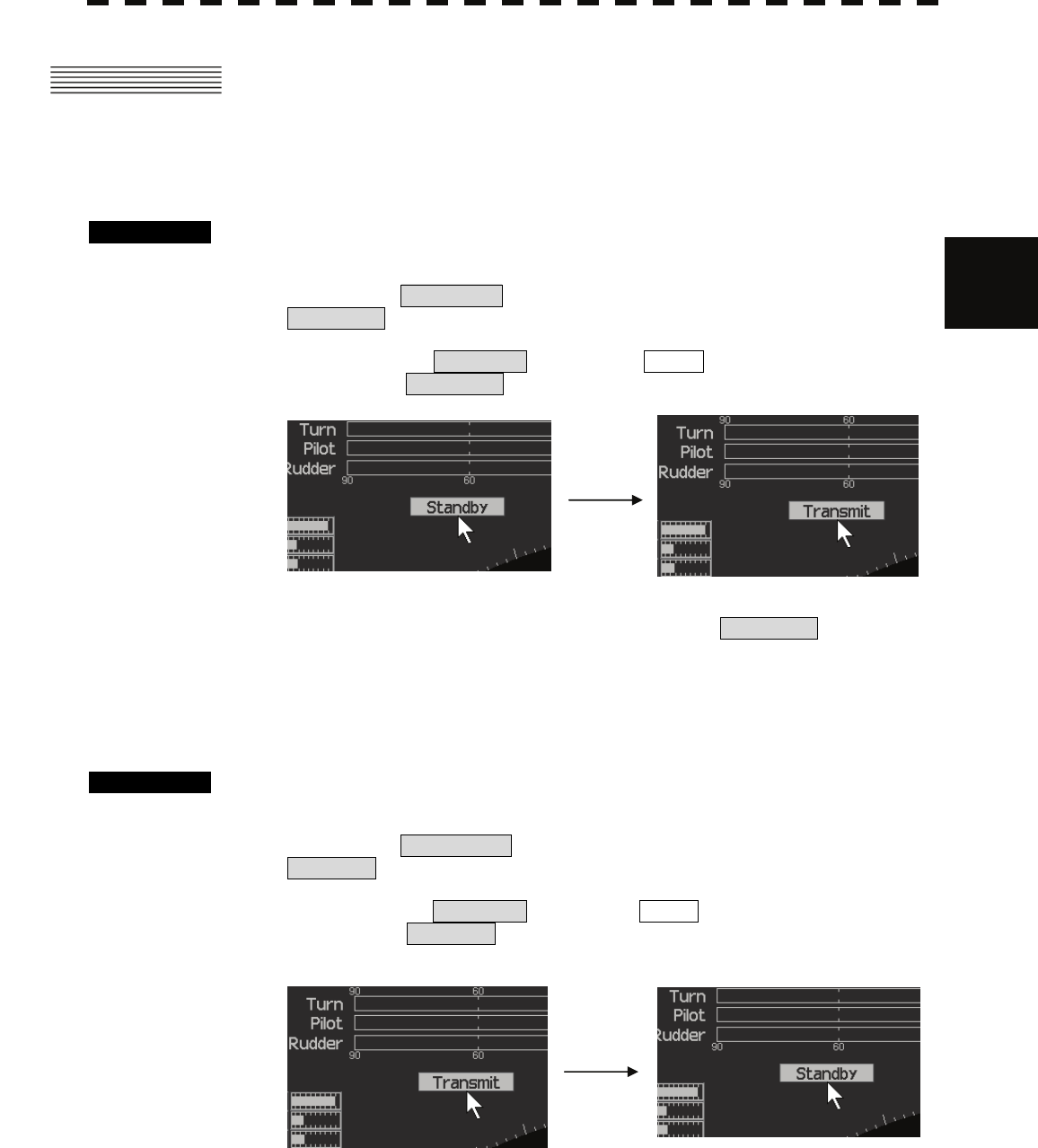
Procedures 1 Press [BRILL] key or set the cursor on BRILL .
2 Set the brilliance value with the [JOG DIAL] or [TRACKBALL] and
[ENTER] key.
ADJUSTING LEVEL IS 0 (full DARK) TO 63(full BRIGHT).
3.3.2 Adjust Operation Panel Brilliance [PANEL]
Procedures 1 Press [PANEL] key to adjust the brilliance of the operation panel light.
There are five brilliance levels (include off) , and brilliance increases by one level each
time the [PANEL] key is pressed. When it reaches the highest level, it is resumed to the
lowest level (off).
In consideration of the ambient brightness, adjust panel brilliance that is high enough to
read the characters on the operation panel but does not glare.
3.3.3 Switch Day/Night Mode [DAY/NIGHT]
The day/night mode changes in the following sequence each time the [DAY/NIGHT] key is pressed:
Qr set the cursor on DAY/NIGHT icon and press ENTER.
The current mode is indicated at the upper right of the radar display.
The brilliance level and the display color in accordance with the selected mode is saved.
DAY1 DAY2 DAY3 DAY4 NIGHT1 NIGHT2 NIGHT3 NIGHT4

3-10
3
3.3 PREPARATION y
y y
3.3.4 Adjust Brilliance of Information on Radar Display
(Brilliance Setting)
Brilliance can be adjusted for each item of information (shown below) on the radar display by operating the
menu.
RADAR VIDEO & TRAILS, FIX RANGE RING, VRM, EBL & P-LINE, BEARING SCALE, CHARACTER,
AIS/VECTOR, PANEL
Procedures 1 Press [MENU] key or set cursor to Menu and press [ENTER] key.
Place the cursor over [1.BRILLIANCE] with trackball and then press
[ENTER] key.
The Brilliance Setting menu will appear.
2 Select the item with trackball for which brilliance is to be adjusted,
pressing [ENTER] key.
The brilliance levels menu will appear.
3 Select the brilliance level number to be set with trackball, pressing the
[ENTER] key.
The selected brilliance level will be set.
Exit 1 Press [MENU] key.
The menu will be closed.
Note: The brilliance levels set here are saved in accordance with the day/night mode.
3.3.5 Adjust Sound Volume (Buzzer Volume)
Procedures 1 Press [MENU] key .
Place the cursor over [3.SETTING] with trackball and then press
[ENTER] key.
The setting menu will appear.
2 Place the cursor over [1.BUZZER LEVEL] with trackball and then press
[ENTER] key.
The buzzer levels menu will appear.
3 Select the volume number to be set with trackball, and press the
[ENTER] key.
The selected volume level will be set.
Exit 1 Press [MENU] key.
The menu will be closed.

3-11
3.3.6 Reset Alarm Buzzer [ALARM ACK]
When an audible alarm is issued, use ALARM ACK to acknowledge the alarm information, stop the alarm
buzzing, and stop the alarm lamp flashing. (If more than one alarm has occurred, press the switch for each
alarm indication.) The alarm stops buzzing, but the alarm indication does not disappear.
Procedures 1 Press [ALARM ACK] key.
The alarm will stop buzzing.
3.3.7 Set Display Color
Color can be adjusted for each item of information (shown below) on the radar display by operating the menu.
1.ECHO Adjusts the colors of radar echoes.
2.TRAILS Adjusts the colors of radar trails.
3.ECHO BACK GROUND Adjusts the background color inside the bearing scale.
4.DATA BACK GROUND Adjusts the background color outside the bearing scale.
5.OTHERS Adjusts the colors of characters and etc.
6. OWN MARK Adjusts the colors of own ship mark.
7.AIS/VECTOR Adjusts the colors of the symbol of AIS and own ship’s vector.
8.VRM Adjusts the colors of VRM.
Procedures 1 Press [MENU] key .
Place the cursor over [2.COLOR] with trackball and then press [ENTER]
key.
The color-setting menu will appear.
2 Select the item with trackball for which color is to be adjusted, press
[ENTER] key.
The kinds of color menu will appear.
Select the color to be set with trackball, pressing [ENTER] key.
The selected color will be set.
Exit 1 Press [MENU] key.
The menu will be closed.
Note: The display color set here are saved in accordance with the day/night mode.
3-12
3
3.4 BASIC OPERATIONS y
y y
3.4 BASIC OPERATIONS
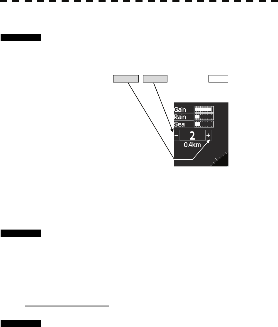
3.4.1 Start Transmission [TX]
Procedures 1 Press [TX] key.
The radar will start transmission and the antenna will start rotating.
The indication STANDBY at the upper left of the radar display changes to
TRANSMIT .
Qr set the cursor on STANDBY icon and press ENTER.
Also changes to TRANSMIT .
Note: The radar does not start transmission if you press [TX] key while PREHEAT is indicated.
3.4.2 Stop Transmission [STBY]
Procedures 1 Press [STBY] key.
The radar will stop transmission and the antenna will stop rotating.
The indication TRANSMIT at the upper left of the radar display changes to
STANDBY .
Qr set the cursor on TRANSMIT icon and press ENTER.
Also changes to STANDBY .
3-13
3.4.3 Change Range (Observation Range Scale) [+RANGE-]
Procedures 1 Press [+RANGE-] key or [RANGE-] key to set the range to the scale
required for target observation.
To observe long-range targets, press upper side of this key.
To zoom and observe a short-range target near the own ship, press lower side of this key.
Qr set the cursor on RANGE + , RANGE - icon and press ENTER.
3.4.4 Tune
This control is used to tune the receiver.
When the tuning does not match, the receiver sensitivity decreases and the operator may miss weak or distant
target.
Procedures 1 Press [+RANGE-] key to select 16km or 32 m.
2 Turn [TUNE] control.
Adjust the video for best presentation.
If radar display does not show a weak target, adjust the control until the tuning bar on the
upper left of the screen indicates the maximum.
To use Auto tuning mode
Procedures 1 Continue pressing [TUNE] control until the character on the right of the
tuning bar changes to “A”.
Select auto tuning mode.
2 Continue pressing [TUNE] control again.
“A” on the right of tuning bar changes to “M”, changes to manual mode.
Note: After tune adjustment with software button once, push [TUNE] knob for tune adjustment
with [TUNE] knob.
3-14
3
3.4 BASIC OPERATIONS y
y y
3.4.5 Control Sensitivity [GAIN]
Procedures 1 Control noise on the radar display by turning the [GAIN] control until
targets can be easily observed.
Turning [GAIN] control clockwise increases sensitivity.
Turning [GAIN] control counterclockwise decreases sensitivity.
Turning the [GAIN] control clockwise increases receiving sensitivity and extends the radar
observation range. If the sensitivity is too high, the receiver noise increases reducing the
contrast between the targets and the background video. As a result, the targets become
obscure on the radar display.
To observe densely crowded targets or short-range targets, turn the [GAIN] control
counterclockwise to reduce the sensitivity so that the targets are easy to observe. However,
be careful not to overlook important small targets.
Note: After gain adjustment with software button once, push the [GAIN] knob for gain
adjustment with [GAIN] knob.
3.4.6 Suppress Sea Clutter [SEA]
Procedures 1 Control the sea clutter returns on the radar display by turning the [SEA]
control until targets can be easily observed.
Turning [SEA] control clockwise suppresses sea clutter returns.
Turning [SEA] control counterclockwise intensifies sea clutter returns.
The sea clutter suppression function suppresses sea clutter returns by decreasing the receiving
sensitivity on a short range.
Turning the [SEA] control clockwise heightens the effect of sea clutter suppression.
However, be careful that excessive suppression causes low signal-strength targets such as
buoys and boats to disappear from the radar display.
Note: After STC adjustments with software button once, push the [SEA] knob for STC
adjustment with [SEA] knob.
When using the [SEA] function, never set the
suppression level too high canceling out all image
noises from the sea surface at close range.
Detection of not only echoes from waves but also
targets such as other ships or dangerous objects will
become inhibited.
When using the [SEA] function, make sure to choose
the most appropriate image noise suppression level.
CAUTION
3-15
3.4.7 Suppress Rain/Snow Clutter [RAIN]
Procedures 1 Control the rain/snow clutter returns on the radar display by turning the
[RAIN] control until targets can be easily observed.
Turning [RAIN] control clockwise suppresses rain/snow clutter returns.
Turning [RAIN] control counterclockwise intensifies rain/snow clutter returns.
When the [RAIN] control is turned clockwise, the rain/snow clutter suppression function
suppresses rain/snow clutter returns and gets targets hidden by rain/snow clutter returns to
appear on the radar display. However, be careful that excessive suppression may cause small
targets to be overlooked. Since the rain/snow clutter suppression function also has the effect
of suppressing sea clutter, the suppression efficiency improves when the [RAIN] control is
used with the [SEA] control. In general, turn the [RAIN] control fully to the left.
Note: After rain adjustment with software button once, push the [RAIN] knob for rain
adjustment with [RAIN] knob.
When using the [RAIN] function, never set the
suppression level too high canceling out all image
noises from the rain or snow at the close range.
Detection of not only echoes from the rain or snow but
also targets such as other ships or dangerous objects
will become inhibited.
When using the [RAIN] function, make sure to choose
the most appropriate image noise suppression level.
CAUTION
3-16
3
3.4 BASIC OPERATIONS y
y y
3.4.8 Reject Radar Interference [IR]
Procedures 1 Place the cursor over [IR]icon at the upper right of the radar display with
trackball and then press [ENTER] key.
Each time [ENTER] key is pressed, changes in the following sequence.
Rejection levels of the interference rejecter
IR OFF: Interference rejecter off
IR LOW: Interference rejection level - low
IR MEDIUM: Interference rejection level - moderate
IR HIGH: Interference rejection level - high
When a high interference rejection level is selected, the radar’s ability of detecting small
targets such as buoys and small boats lowers.
In general, [IR LOW] should be selected.
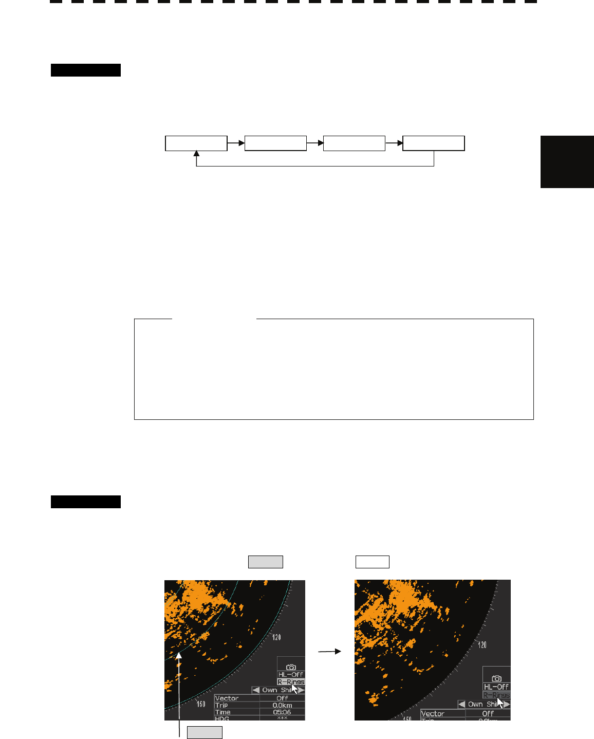
3.4.9 Hide/Display Range Rings (RINGS)
Procedures 1 Press [RR] key.
The range rings display switches back and forth between display and non-display each
time [RR] key is pressed.
Qr set the cursor on R-Rings icon and press ENTER.
R-Rings
z When viewing a radar beacon or SART signal, select
IR OFF (Interference Rejector OFF) because IR
processing suppresses the video.
Attention
IR OFF IR LOW IR MEDIUM IR HIGH
3-17
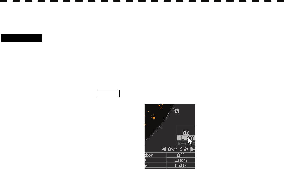
3.4.10 Hide Ship’s Heading Line (HL OFF)
Procedures 1 Hold down [HL OFF] key.
The ship’s heading line is hidden while [HL OFF] key is held down.
The ship’s heading line (HL) that presents the course of own ship is always shown on the radar
display. The heading line is hidden while [HL OFF] key is held down, so the targets below
the heading line can be easily observed.
Or click hold the HL-OFF icon. While click hold ,the ship’s heading line is hidden.

3-18
3
3.5 GENERAL OPERATIONS y
y y
3.5 GENERAL OPERATIONS
3.5.1 Move Cross Cursor Mark by Trackball
The cross cursor mark + is used for position designation and other purposes in various operating
procedures. The cross cursor mark + moves in coupling with the trackball. If the trackball is rotated up
and down or right and left, the cross cursor mark follows the move of the trackball.
Operators must be familiar with trackball operation before running the system.
Operation inside Radar Video PPI
The cross cursor mark as shown at right is displayed inside the radar video PPI.
1) The distance and bearing between own ship and the cross cursor mark + , and the degrees of
latitude and longitude are digitally indicated at the lower left of the radar display.
NOTE: The display of degrees of latitude and longitude needs the connection of GPS and heading
sensor.
Operation outside Radar Video PPI
As shown at right, the cursor mark changes into the pointer
outside the radar video PPI.
1) Use the pointer to operate software buttons.
2) Use the pointer to select menu items.
3.5.2 Use EBLs (Electronic Bearing Lines) [EBL1/EBL2]
EBLs (Electronic Bearing Lines) are indispensable to the measurement of bearings.
Operators must be familiar with the operation of EBLs beforehand.
EBL1 Operation
If EBL2 is selected or EBL1 is not displayed, press [EBL1/EBL2] key to select EBL1 before starting
operation.
(The currently selected EBL is shown in reverse video at the lower left of the radar display.)
Procedures 1 Press [EBL1/EBL2] key to select EBL1.
EBL1 at the lower left of the radar display will be shown in reverse video, and EBL1
becomes operable.
2 Adjust the bearing of EBL1 with [JOG DIAL] or [TRACKBALL].
3 Press [ENTER] key.
The bearing of EBL1 is fixed .
3-19
EBL2 Operation
If EBL1 is selected or EBL2 is not displayed, press [EBL1/EBL2] key to select EBL2 before starting
operation.
(The currently selected EBL is shown in reverse video at the lower right of the radar display.)
Procedures 1 Press [EBL1/EBL2] key to select EBL2.
EBL2 at the lower left of the radar display will be shown in reverse video, and EBL2
becomes operable.
2 Adjust the bearing of EBL2 with [JOG DIAL] or [TRACKBALL].
3 Press [ENTER] key.
The bearing of EBL2 is fixed.
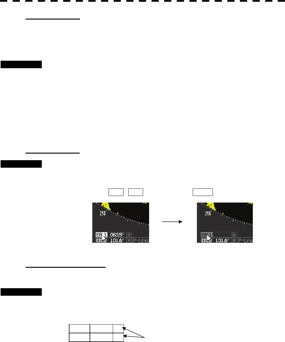
CLEARING EBL
Procedures 1 Hold down [EBL1/EBL2] key.
The EBL (current selected EBL) display will disappear.
Or set the cursor EBL1 / EBL2 icon and hold press ENTER.
SETTING EBL DISPLAY
Select EBL true and relative bearing display.
Procedures 1 Place the cursor over the position at the bottom left as following figure.
Press [ENTER] key.
The bearing mode is switched back and forth between true and relative.
EBL1
EBL2
123.4°
123.4°
R
R

3-20
3
3.5 GENERAL OPERATIONS y
y y
3.5.3 Use VRMs (Variable Range Markers) [VRM1/VRM2]
This function is to display and select variable range markers (VRMs). Two VRMs are available: VRM1 is
represented as a broken line, and VRM2 as a dotted line.
VRM1 Operation
If VRM2 is selected or VRM1 is not displayed, press [VRM1/VRM2] key to select VRM1 before
starting operation.
(The currently selected VRM is shown in reverse video at the lower right of the radar display.)
Procedures 1 Press [VRM1/VRM2] key to select VRM1.
VRM1 at the lower right of the radar display will be shown in reverse video, and VRM1
becomes operable.
2 Adjust the range of VRM1 with [JOG DIAL] or [TRACKBALL].
3 Press [ENTER] key .
The range of VRM1 is fixed .
VRM2 Operation
If VRM1 is selected or VRM2 is not displayed, press [VRM1/VRM2] key to select VRM2 before
starting operation.
(The currently selected VRM is shown in reverse video at the lower right of the radar display.)
Procedures 1 Press [VRM1/VRM2] key to select VRM2.
VRM2 at the lower right of the radar display will be shown in reverse video, and VRM2
becomes operable.
2 Adjust the range of VRM2 with [JOG DIAL] or [TRACKBALL].
3 Press [ENTER] key .
The range of VRM2 is fixed.
3-21
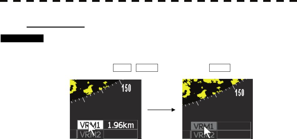
CLEARING VRM
Procedures 1 Hold down [VRM1/VRM2] key.
The VRM (current selected VRM) display will disappear.
Or set the cursor VRM1 / VRML2 icon and hold press ENTER.

3-22
3
3.5 GENERAL OPERATIONS y
y y
3.5.4 Use P-LINEs (Parallel Index Lines) [P-LINE]
P-LINE1 Operation
If P-LINE2 is selected or P-LINE1 is not displayed, press [P-LINE] key to select P-LINE1 before
starting operation.
(The currently selected P-LINE is shown in reverse video at the lower left of the radar display.)
Procedures 1 Press [P-LINE] key to select P-LINE1.
P-LINE1 at the lower left of the radar display will be shown in reverse video, and
P-LINE1 becomes operable.
2 Adjust the range from own ship’s position of P-LINE1 with [JOG DIAL]
or [TRACKBALL].
3 Press [ENTER] key.
The range of P-LINE1 is fixed.
P-LINE2 Operation
If P-LINE1 is selected or P-LINE2 is not displayed, press [P-LINE] key to select P-LINE2 before
starting operation.
(The currently selected EBL is shown in reverse video at the lower right of the radar display.)
Procedures 1 Press [P-LINE] key to select P-LINE2.
P-LINE2 at the lower left of the radar display will be shown in reverse video, and
P-LINE2 becomes operable.
2 Adjust the bearing of EBL1 with [JOG DIAL] or [TRACKBALL].
3 Press [P-LINE] key.
The range of P-LINE2 is fixed.
CLEARING P-LINE
Procedures 1 Hold down [P-LINE] key.
Or set the cursor to P-Line1 / P-Line2 icon and hold press ENTER
The P-LINE (current selected P-LINE) display will disappear.
3-23
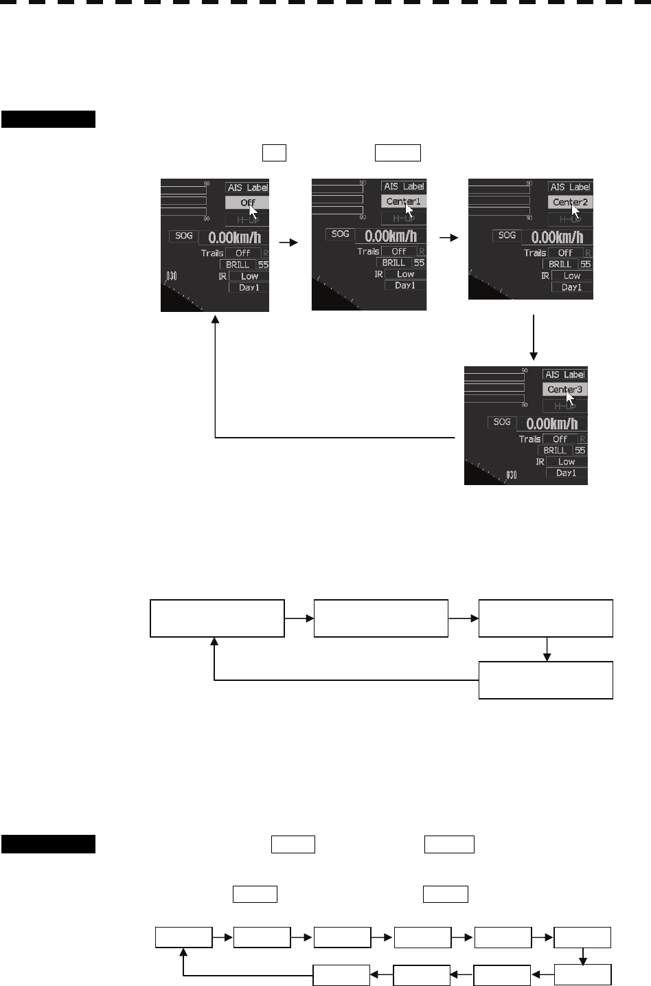
3.5.5 Move Own Ship’s Display Position [OFF CENT]
The own ship’s position can be moved from the display center to stern or bow direction.
Procedures 1 Press [OFF CENT] key.
Or set the cursor to off icon and press ENTER
The own ship’s position will be moved from the display center as following
sequence each time the [OFF CENT] key is pressed:
3.5.6 Display Other Ships’ Trails [TRAILS]
Other ships’ movements and speeds can be monitored from the lengths and directions of their trails, serving for
collision avoidance.
Procedures 1 Set the cursor to TRAIL icon and press ENTER .
Trails length will be changed as following sequence .
Each time the TRAIL icon is selected and press ENTER .
2Scan 15sec 30sec 1min 2min
3min
OFF
6min 5min 4min
center 3
center 1 center 2
off
60% of display radius
in the stern direction
40% of display radius
in the stern direction
On center
20% of display radius
in the stern direction
center 1 center 2
off
center 3
3-24
3
3.5 GENERAL OPERATIONS y
y y
Erasing Trails Data
Procedures 1 Set the cursor to TRAIL icon and hold press more than 2second.
All the stored trails data will be erased.
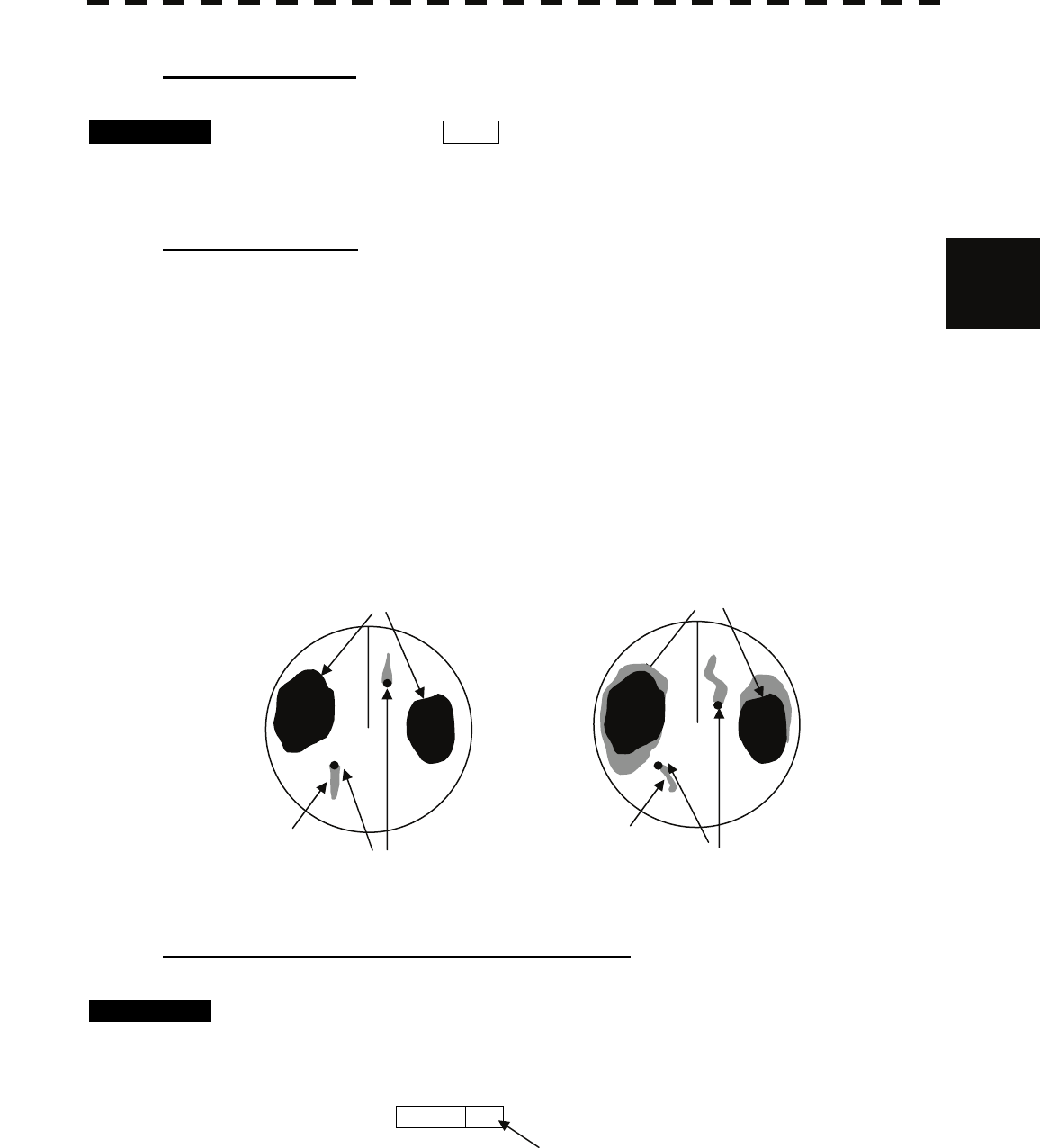
Trails Motion Mode
There are two types of trails: relative motion trails and true motion trails.
Relative motion trails: The system plots the trails of a target at a position relative to the own ship.
The operator can easily judge whether the target is approaching the own
ship.
While the own ship is moving, the system also plots the trails of land and
other fixed targets.
True motion trails: The system plots the absolute motion trails of a target, irrespective of the
own ship’s position.
The operator can easily judge the course and speed of the target.
The system does not plot the trails of land and other fixed targets.
NOTE : The display of true motion trail needs the connection of the speed sensor
and heading sensor.
Changing Motion Mode of Trails (Trails mode)
Procedures 1 Place the cursor over the position at the upper right as following figure.
Press [ENTER] key.
The motion mode of trails is switched back and forth between true and relative.
2Scan R
Land
Ship
Trails
Land
Ship
Trails
True Motion Trails Relative Motion Trails
3-25
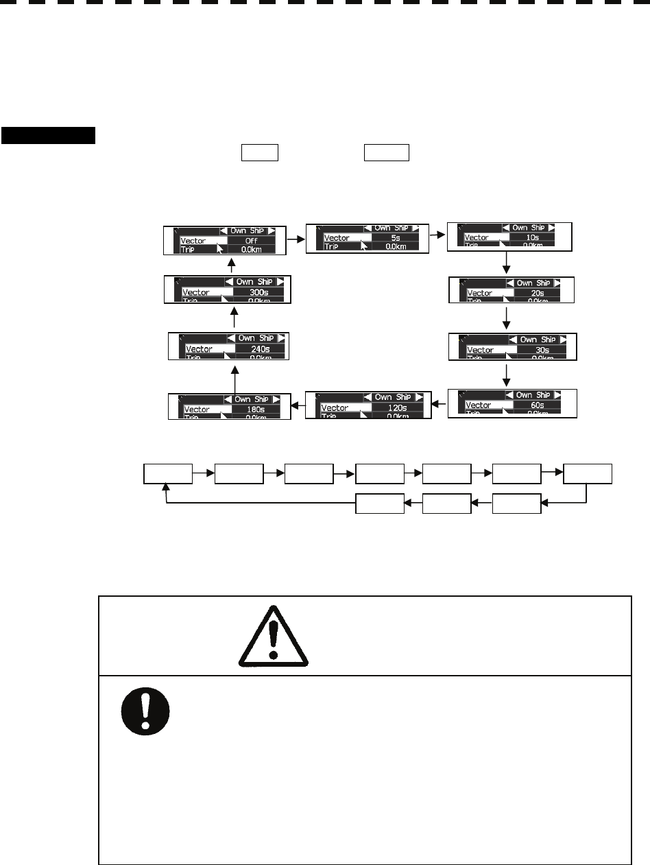
3.5.7 Display Own Vector [OWN VECT]
NOTE: The display of own vector need the connection of the speed sensor and the
Heading sensor.
Procedures 1 Press [OWN VECT] switch.
Or set cursor to Vector icon and press ENTER.
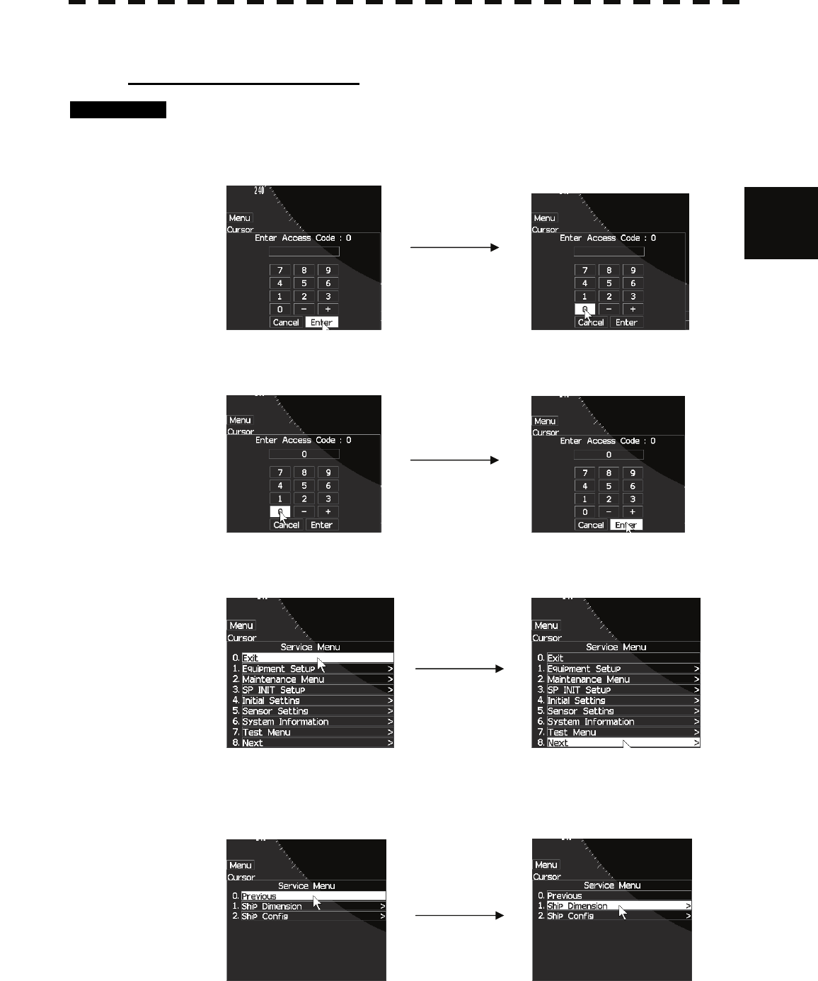
Own vector is switched each time ,the vector length is changed as following.
There are shown 2 vectors, one drawn from the bow and the other one from the stern. The
vector will be straight when the vessel doesn’t turn and curved when the vessel turns.
OFF 5sec 10sec 20sec 30sec 60sec 120sec
180sec
240sec 300sec
The accuracy from the vectors are depending on the
accuracy from the (D)GPS sensors.
With longer vectors, the accuracy will be lower.
The vectors are calculated with the situation at that
time. When there will be some changed influence from
wind, water current etc, are not shown before the
vessel is influenced by this.
CAUTION
3-26
3
3.5 GENERAL OPERATIONS y
y y
3.5.8 EDITING OWN MARK
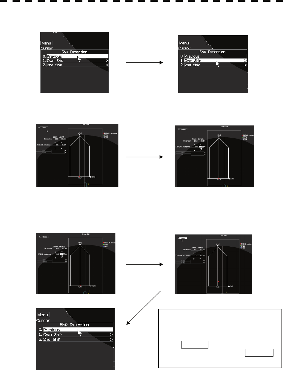
Editing own mark dimension
Procedures Hold press [ MENU] key more than 5 second.
Or set the cursor to the Menu icon and hold press more than 5 second.
Service menu will be displayed.
Select “0” . Press ENTER key.
Service menu will be open. Select 8.Next item.
Service menu (Next page) will be open. Select 1.Ship Dimension.
And press ENTER.
3-27
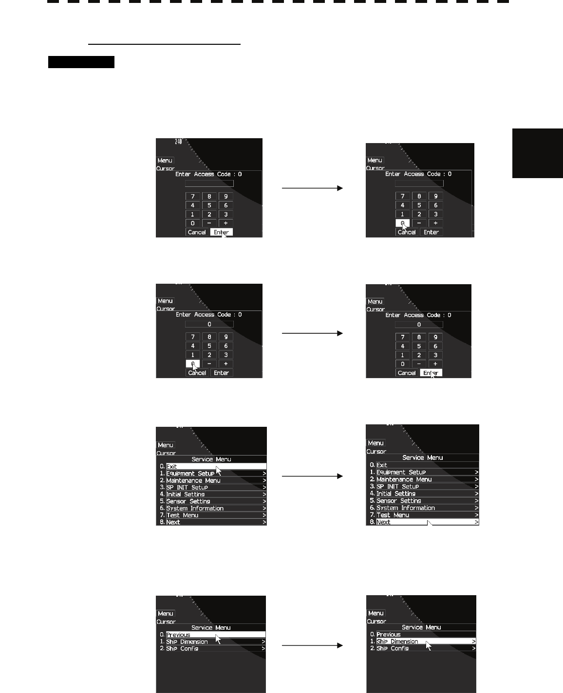
Input Own/ 2nd ship selection menu will be open. Select 1.Own ship.
Ship dimension input menu will be open. Own ship dimension data input are ready.
Place the cursor over the item to change
the dimension with trackball and then
press [ENTER] key.
Decide the value with [JOG DIAL]
or trackball and then press
[ENTER] key.
Own ship dimension data input is
finished.
If you want to editing 2nd ship
dimension, select 2. 2nd Ship and
press ENTER .
In case own ship only, press MENU
to quit.
3-28
3
3.5 GENERAL OPERATIONS y
y y
Editing 2nd ship dimension
Procedures Procedure is similar to editing own ship dimension.
Hold press [ MENU] key more than 5 second.
Or set the cursor to the Menu icon and hold press more than 5 second.
Service menu will be displayed.
Select “0” . Press ENTER key.
Service menu will be open. Select 8.Next item.
Service menu (Next page) will be open.
Select 1.Ship Dimension.
And press ENTER.
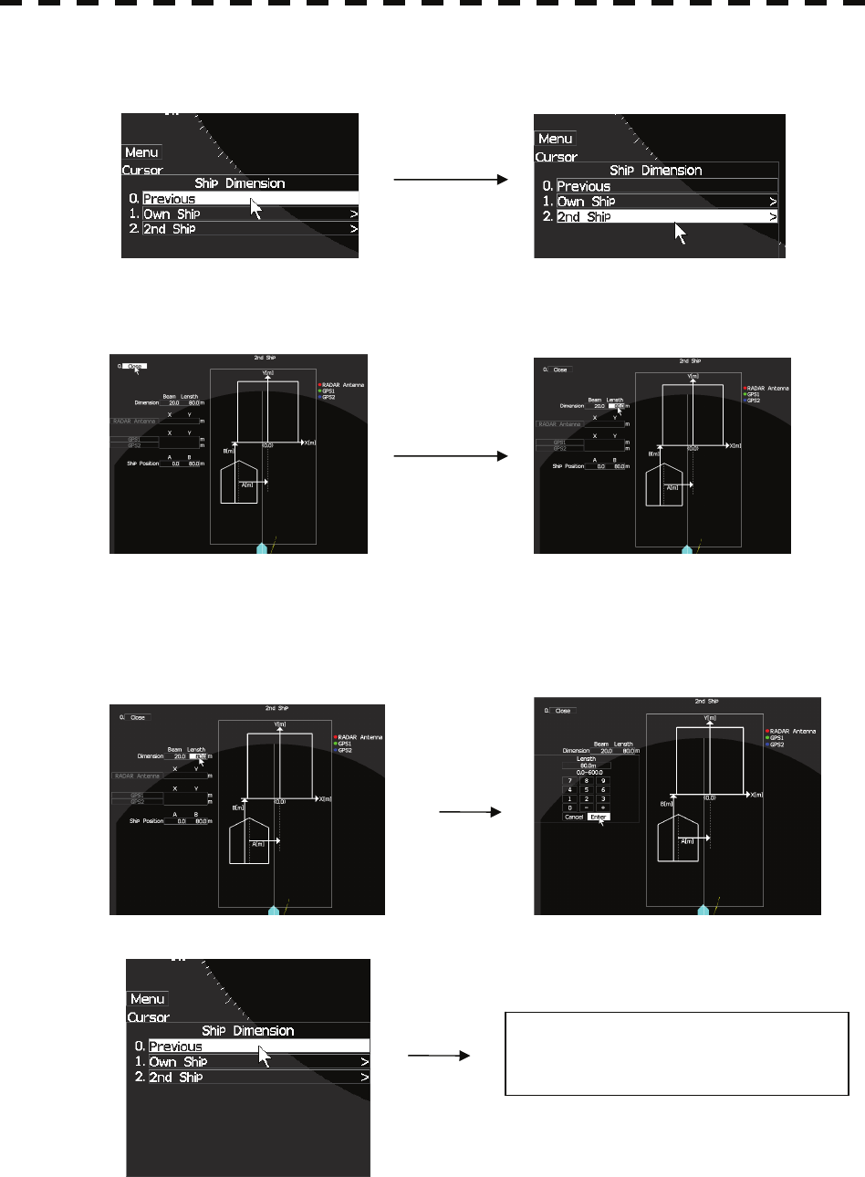
3-29
Input ship selection menu will be open. Select 2.2nd ship and press ENTER key.
Ship dimension input menu will be open. 2nd ship dimension data input are ready.
Place the cursor over the item to change
the dimension with trackball and then
press [ENTER] key.
Decide the value with [JOG DIAL]
or trackball and then press
[ENTER] key.
2nd ship dimension data input is
finished.
Press MENU key to quit.
3-30
3
3.5 GENERAL OPERATIONS y
y y
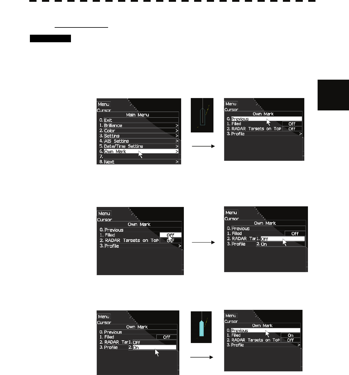
Paint own mark
Procedures 1 Press [ MENU] key .
Main menu will appear.
2 Place the cursor over [6.OWN MARK] with trackball and then press
[ENTER] key.
OWN MARK menu will appear.
3 Place the cursor over [1.FILLED] with trackball and then press [ENTER]
key.
ON/OFF menu will appear.
4 Place the cursor over [ON] with trackball and then press [ENTER] key.
"OFF" will changes to “ON”.
3-31
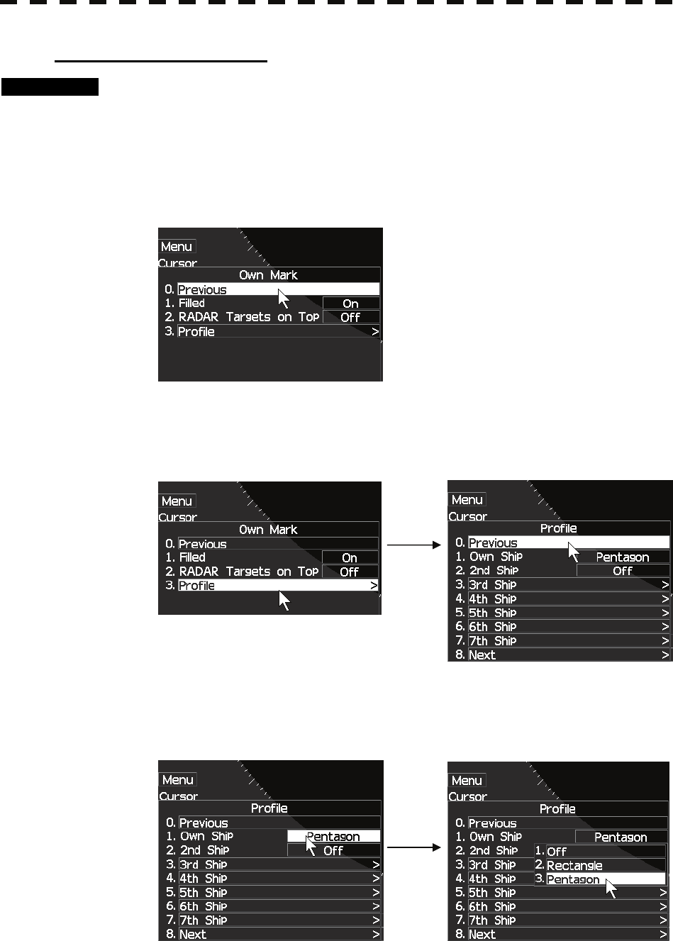
Change own mark’s figure
Procedures 1 Press [ MENU] key.
MAIN MENU will appear.
2 Place the cursor over [6.OWN MARK] with trackball and then press
[ENTER] key.
OWN MARK menu will appear.
3 Place the cursor over [3. PROFILE] with trackball and then press
[ENTER] key.
Own ship profile menu will appear. Select 1.Own Ship.
4 Place the cursor over [RECTANGLE] with trackball and then press
[ENTER] key.
Own mark’s figure will change from “PENTAGON” to “RECTANGLE”.
3-32
3
3.5 GENERAL OPERATIONS y
y y
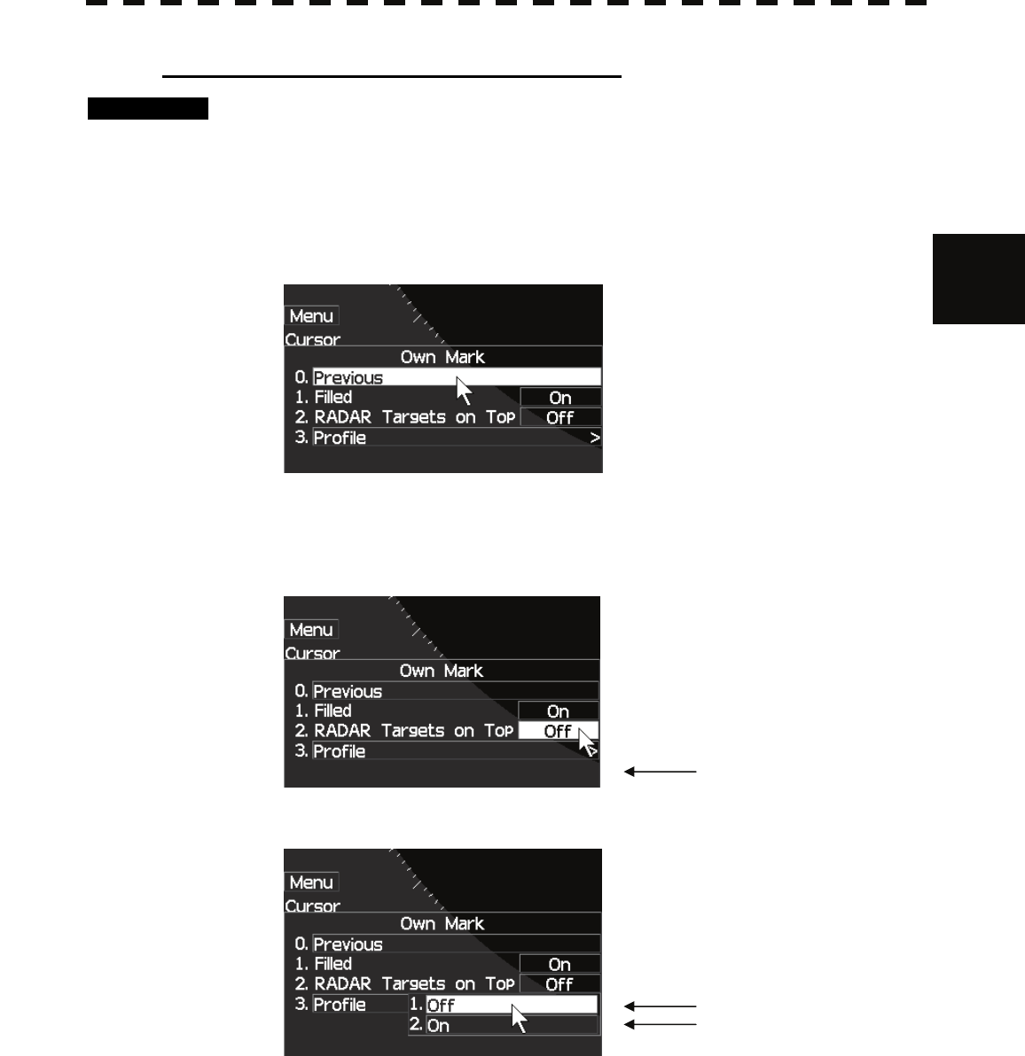
Change the priority of ECHO and OWN MARK
Procedures 1 Press [ MENU] key .
MAIN MENU will appear.
2 Place the cursor over [6.OWN MARK] with trackball and then press
[ENTER] key.
OWN MARK menu will appear.
3 Place the cursor over [2.RADAR Targets ON Top] with trackball and then
press [ENTER] key.
ON/OFF menu will appear.
4 Select “ON” or “OFF" with trackball and then press [ENTER] key.
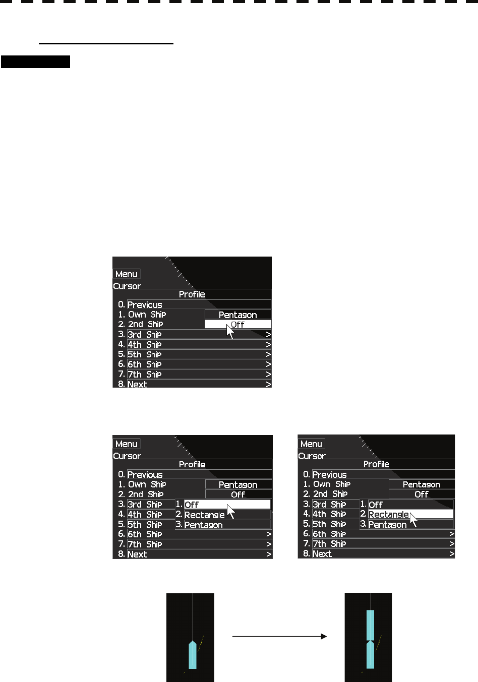
3-33
Change 2nd ship figure
Procedures 1 Press [ MENU] key when radar is standby mode.
MAIN MENU2 will appear.
2 Place the cursor over [6.OWN MARK] with trackball and then press
[ENTER] key.
OWN MARK menu will appear.
3 Place the cursor over [3. PROFILE] with trackball and then press
[ENTER] key.
2nd ship profile menu will appear.
4 Place the cursor over [2.2nd SHIP] with trackball and then press
[ENTER] key.
5 Place the cursor over [RECTANGLE] with trackball and then press
[ENTER] key.
2nd ship mark’s figure will be appeared as “RECTANGLE”.
3-34
3
3.5 GENERAL OPERATIONS y
y y
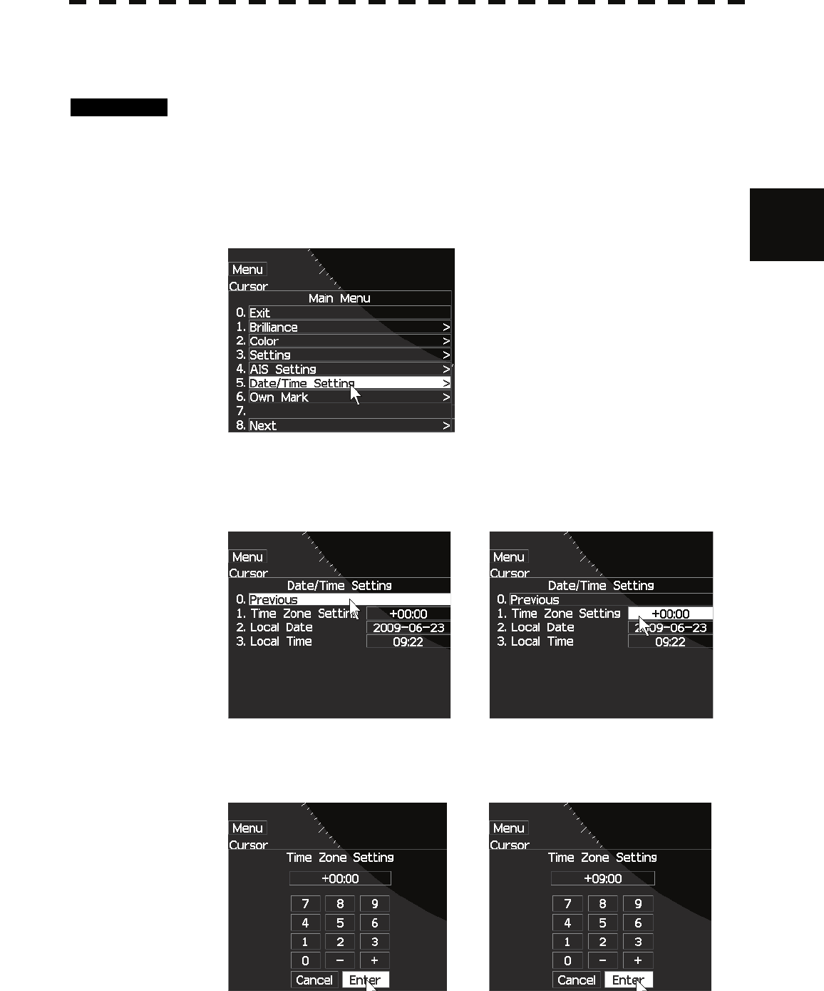
3.5.9 TIME ZONE SETTING
Local time is displayed at the bottom right. Adjust the time as following.
Procedures 1 Press [ MENU] key.
MAIN MENU will appear.
2 Place the cursor over [5.Date/Time Setting] with trackball and then press
[ENTER] key.
SETTING menu will appear.
3 Place the cursor over [1.TIME ZONE SETTING] with trackball and then
press [ENTER] key.
TIME ZONE SETTING menu will appear.
4 Adjust the time with [JOG DIAL] or trackball and then press [ENTER] key.
If you adjust with [JOG DIAL], set hour, push [JOG DIAL], and set
minute.
3-35
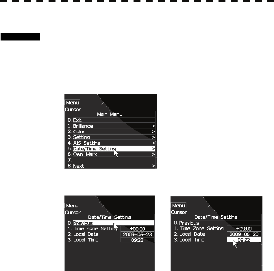
3.5.10 LOCAL TIME SETTING
Procedures 1 Press [ MENU] key.
MAIN MENU will appear.
2 Place the cursor over [5.Date/Time Setting] with trackball and then press
[ENTER] key.
LOCAL TIME SETTING menu will appear.
3 Place the cursor over [1.TIME ZONE SETTING] with trackball and then
press [ENTER] key.
4 Adjust the time with [JOG DIAL] or trackball and then press [ENTER] key.
If you adjust with [JOG DIAL], set hour, push [JOG DIAL], and set
minute.
3-36
3
3.5 GENERAL OPERATIONS y
y y
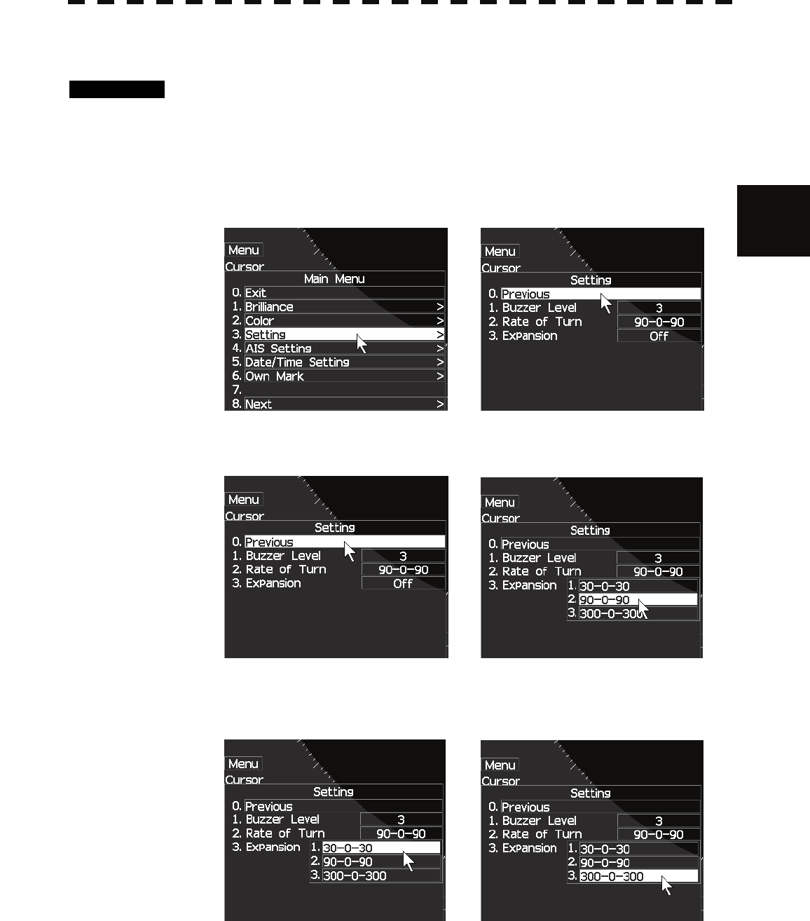
3.5.11 CHANGE THE UNIT OF RATE OF TURN
Procedures 1 Press [ MENU] key.
MAIN MENU will appear.
2 Place the cursor over [3.SETTING] with trackball and then press
[ENTER] key.
SETTING menu will appear.
3 Place the cursor over [2.RATE OF TURN] with trackball and then press
[ENTER] key.
The unit of RATE OF TURN will appears.
4 Select the unit with trackball and then press [ENTER] key.
3-37
3.5.12 DISPLAY AIS LABEL
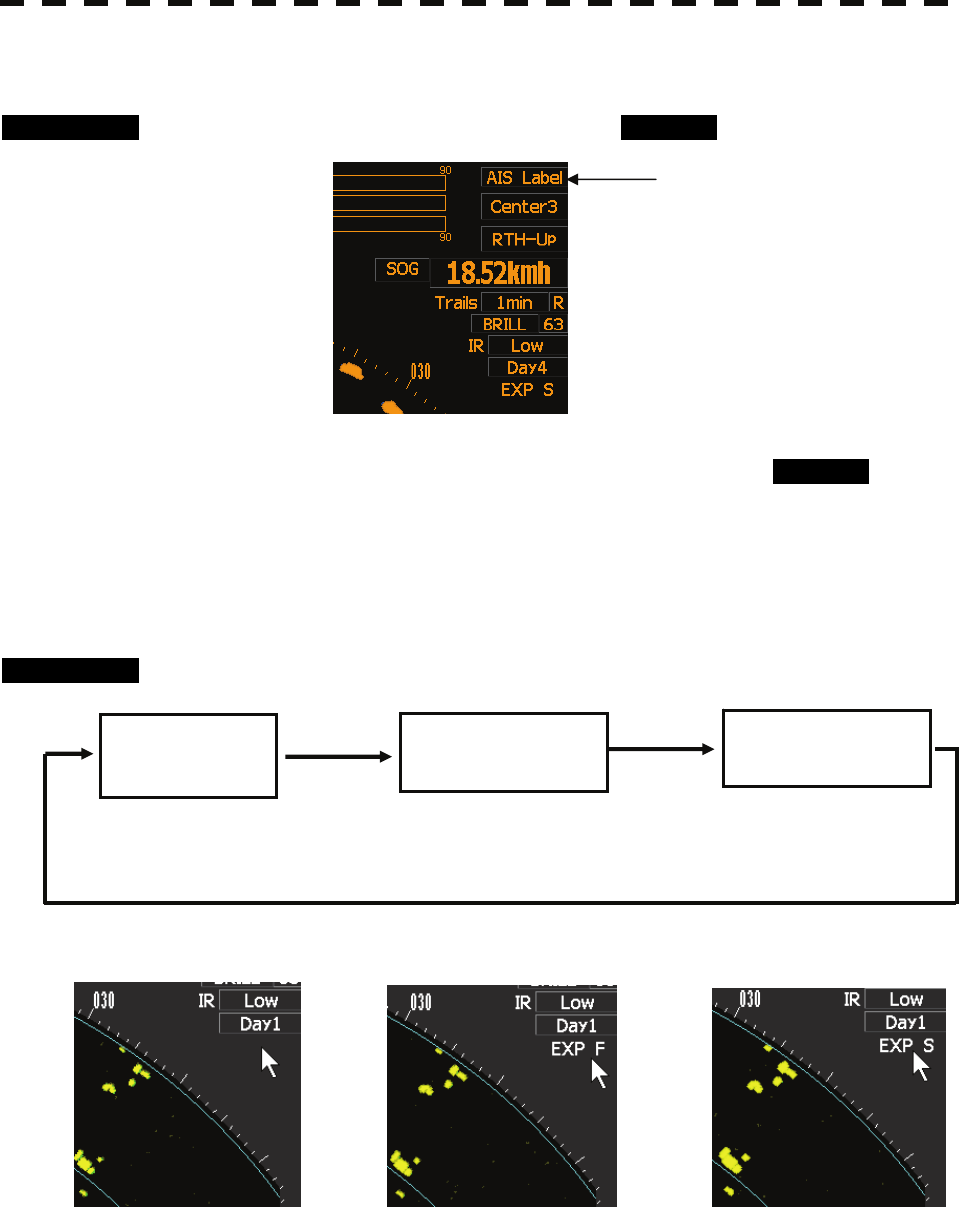
Procedures 1 Press [ AIS LABEL] key or set cursor to AIS Label on screen.
While hold press [ AIS LABEL] key or ,while hold press AIS Label on
screen icon,display the AIS target ship’s name.
3.5.13 ECHO EXPANSION SWITCH
Procedures 1 Press [EXP] key .
Hold press AIS Label
OFF EXP F EXP S
EXPANSION OFF EXPANSION FAIR EZPANSION STRONG

3-38
3
3.6 DISAPLAY USER MAP y
y y
3.6 DISAPLAY USER MAP
Navigation information such as a maximum of 256 points of NAV lines, coastlines, depth contours, and
NAV marks can be displayed, created, read, saved, corrected, and deleted. (This function is available
only when navigation equipment is connected with the system.)
Marks that can be used : 29 types
Lines that can be used : 3 types (solid, broken, and dashed-dotted line)
Color of mark and line that can be used : 7 colors
If radar video is poor visibility caused by user map function, press the [DATA OFF] key to map displays
temporarily off.
3.6.1 Edit User Map
In this system, when the radar is in the transmission state, the user map is displayed all the time.
However, valid latitude / longitude data and true bearing data must be entered into the system.
The user map can be created and edited by performing the following operation.
Plotting a mark
Procedures 1 Press [MENU] key .
Select 8.Next and press [ENTER] key.
Select 4.NAV Information and press [ENTER] key.
Select 1.Make with cursor and press [ENTER] key.
Select 1.Type and press s [ENTER] key.
2 Put the cursor on mark font switching , and press [ENTER] key.
The mark fonts are switched.
3 Put the cursor mark on mark 2.Color, and press [ENTER] key.
The mark colors are switched.
4 Put the cursor on a location of the display at which you want to plot the
mark, and press [ENTER] key.
The specified mark is displayed in the specified shape and color.
To create another mark, repeat the above procedures.

3-39
Plotting a line
Procedures 1 Press [MENU] key .
Select 8.Next and press [ENTER] key.
Select 4.NAV Information and press [ENTER] key.
Select 1.Make with cursor and press [ENTER] key.
Select 1.Type and press s [ENTER] key.
2 Put the cursor on line pattern switching ------- , and press [ENTER]
key.
Line patterns are switched.
3 Put the cursor on line 2.Color, and press [ENTER] key.
Line colors are switched.
4 Put the cursor on a location of the display at which you want to start
plotting a line, and press [ENTER] key.
The start point of the specified line will be displayed.
5 Move the cursor to a location of the display at which you want to finish
plotting the line, and press [ENTER] key.
A line is plotted between the previous point and the end point.
Repeat this procedure so that sequential lines can be plotted.
6 When you want to finish plotting the line, press [ENTER] key at the
previous point.
Line plotting will be terminated.
To plot another line, repeat procedures 4 to 6.

3-40
3
3.6 DISAPLAY USER MAP y
y y
Plotting a mark / line make with latitude and longitude
Procedures 1 Open the Edit User Map menu by performing the following menu
operation.
Press [MENU] key .
Select 8.Next and press [ENTER] key.
Select 4.NAV Information and press [ENTER] key.
Select 1.Edit User Map and press [ENTER] key.
2 Select 2.Make with L/L and press [ENTER] key.
The Make with L/L menu will appear.
3 Put the cursor on line 5. New Mark Input or New Line Input and press
[ENTER] key.
The Mark Input menu and the Line Input menu are switched.
4 Select Mark or Line and press ENTER.
The desired mark font or line pattern is selected.
To add a line, select midpoint --O-- .
5 Select 1.Type and select the color of mark or line to be created.
The desired mark or line color is selected.
6 Select 3.L/L to input the latitude / longitude and press [ENTER] key.
7 Select 4.Enter and press [ENTER] key.
Mark / Line plotting will be terminated.
To create another mark or line, repeat procedures 4 to7.
3-41
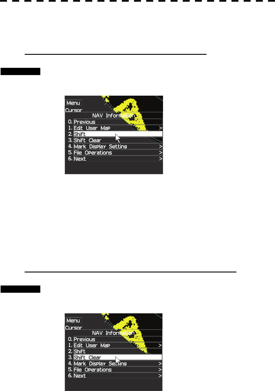
3.6.2 Correct Position on User Map (Shift ).
If the display position on the user map is different from an actual position, it can be changed to the
correct position in manual mode.
Correcting the display position on the user map (Shift).
Procedures 1 Press [MENU] key.
Select 8.Next and press [ENTER] key.
Select 4.NAV Information and press [ENTER] key.
2 Select 2.Shift and press [ENTER] key
3 Put the cursor on a mark or end of a line, and press [ENTER] key.
4 Put the cursor on the point to be corrected, and press [ENTER] key.
Positions of all marks and lines currently displayed will be corrected.
3.6.3 Correct Position on User Map (Shift Clear).
Clearing the corrected user map to its original state (Shift Clear)
Procedures 1 Press [MENU] key.
Select 8.Next and press [ENTER] key.
Select 4.NAV Information and press [ENTER] key.
2 Select 3.Shift Clear and press [ENTER] key.

3-42
3
3.6 DISAPLAY USER MAP y
y y
3.6.4 Set User Map Display (Mark Display Setting)
The user map can be individually displayed (on) or hidden (off).
Setting by type : Setting can be made by mark font and line pattern.
Setting by color : Setting can be made by color of mark or line.
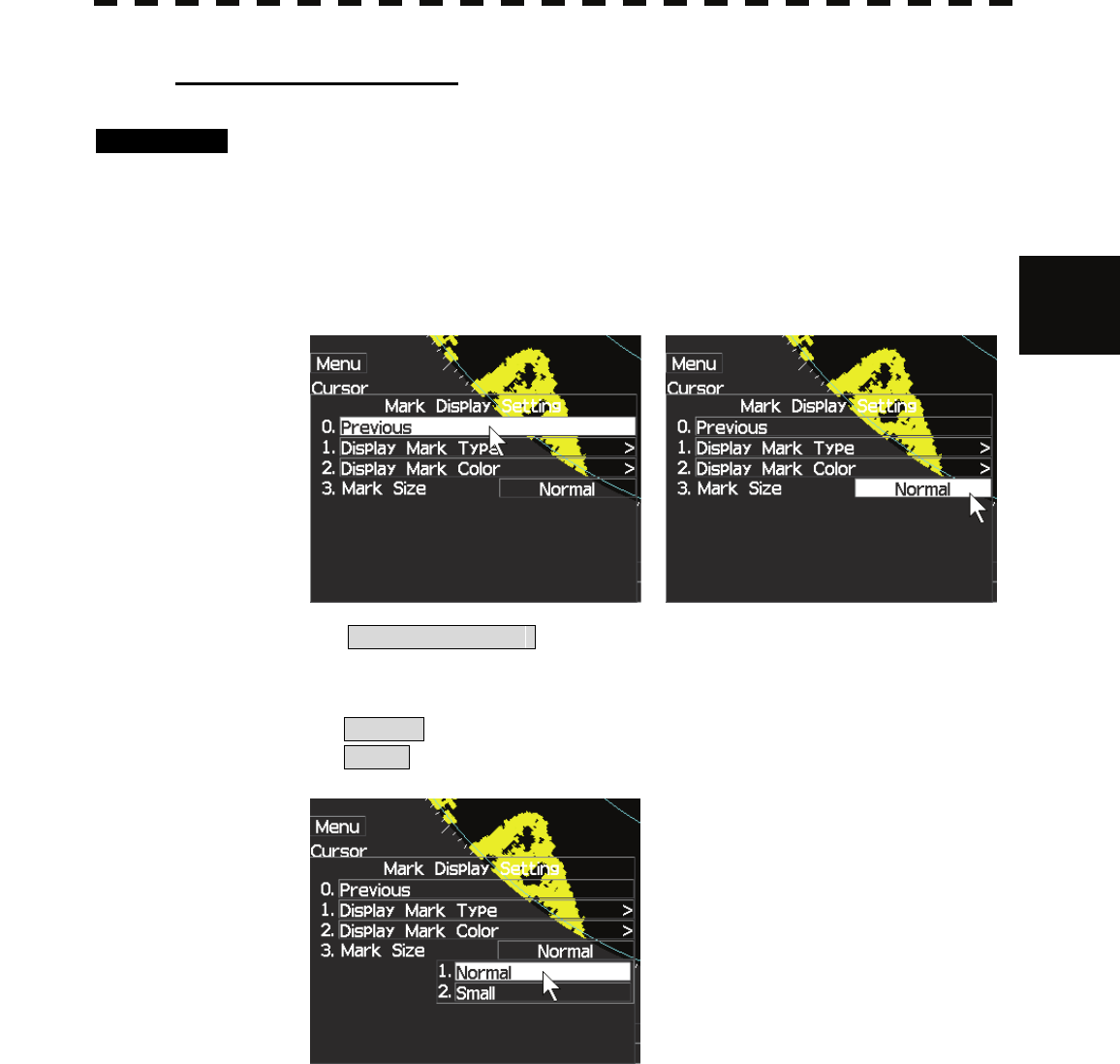
The mark font display size can be selected.
Normal : The mark is displayed in normal size.
Small : The mark is displayed in a size smaller than usual.
Setting display by type
Procedures 1 Press [MENU] key.
Select 8.Next and press [ENTER] key.
Select 4.NAV Information and press [ENTER] key.
Select 4.Mark Display Setting and press [ENTER] key.
The Mark Setting display will appear.
2 Open the Display Mark Type menu by performing the following menu
operation.
Select 1.Display Mark Type and press [ENTER] key.
3 Select 1.ALL sand press [ENTER] key.
Selected items for All will be displayed.
4 Select 3.Individual and press[ENTER]key.
Off : All types are not displayed.
On : All types are displayed.
Individual : Setting by type is activated.
5 Select each mark font / line pattern display and press [ENTER].
On : Displayed.
Off : Not Displayed.
3-43
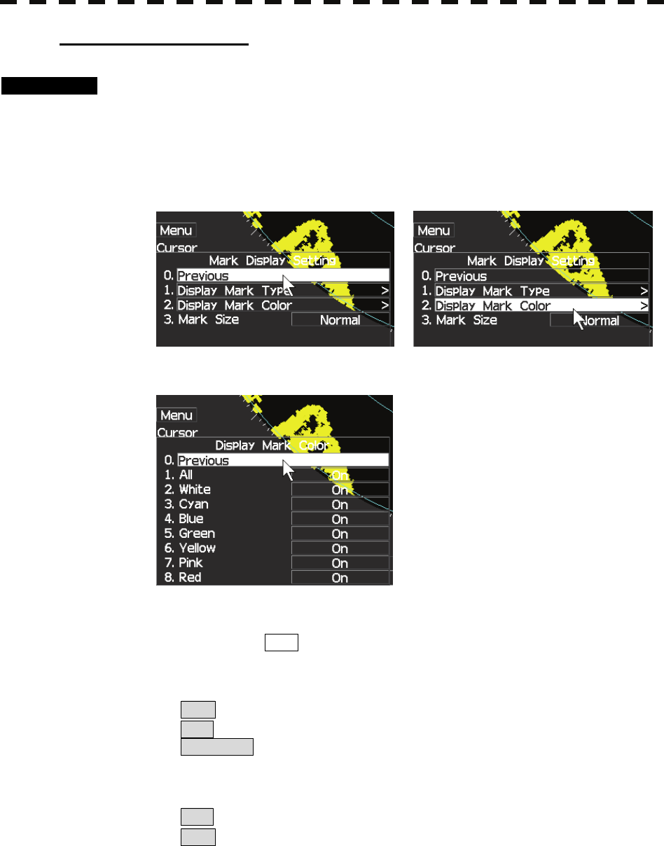
Setting display by color
Procedures 1 Press [MENU] key.
Select 8.Next and press [ENTER] key.
Select 4.NAV Information and press [ENTER] key.
The Mark Setting menu will appear.
2 Open the Display Mark Color menu by performing the following menu
operation.
Select 2.Display Mark Color and press [ENTER] key.
3 Select 1.ALL and press [ENTER] key.
Selected items for All will be displayed.
4 Select 3.Individual and press [ENTER] key.
Off : All colors are not displayed.
On : All colors are displayed.
Individual : Setting by color is activated.
5 Select each mark font / line pattern display.
On : Displayed.
Off : Not Displayed.
3-44
3
3.6 DISAPLAY USER MAP y
y y
Setting the mark font size
Procedures 1 Press [MENU] key.
Select 8.Next and press [ENTER] key.
Select 4.NAV Information and press [ENTER] key.
The Mark Setting display will appear.
2 Open the Select Mark Size menu by performing the following menu
operation.
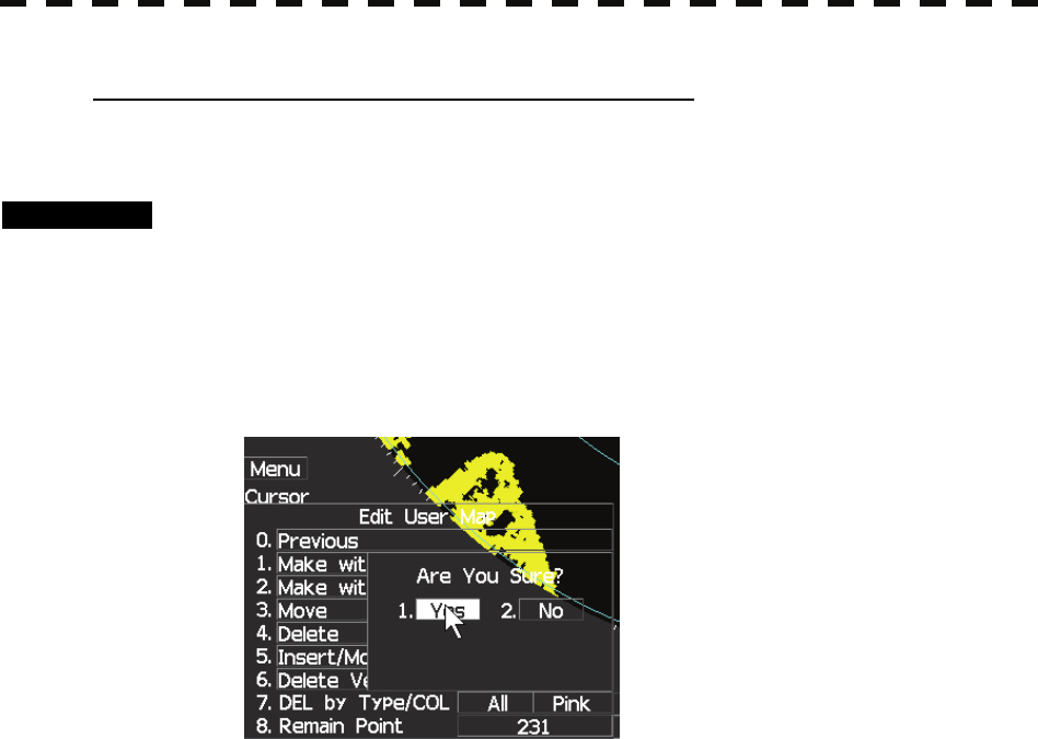
4. Select Mark Size
3 Select mark font size to be set and press [ENTER]key.
Normal : The mark is displayed in normal size.
Small : The mark is displayed in a size smaller than usual.
3-45
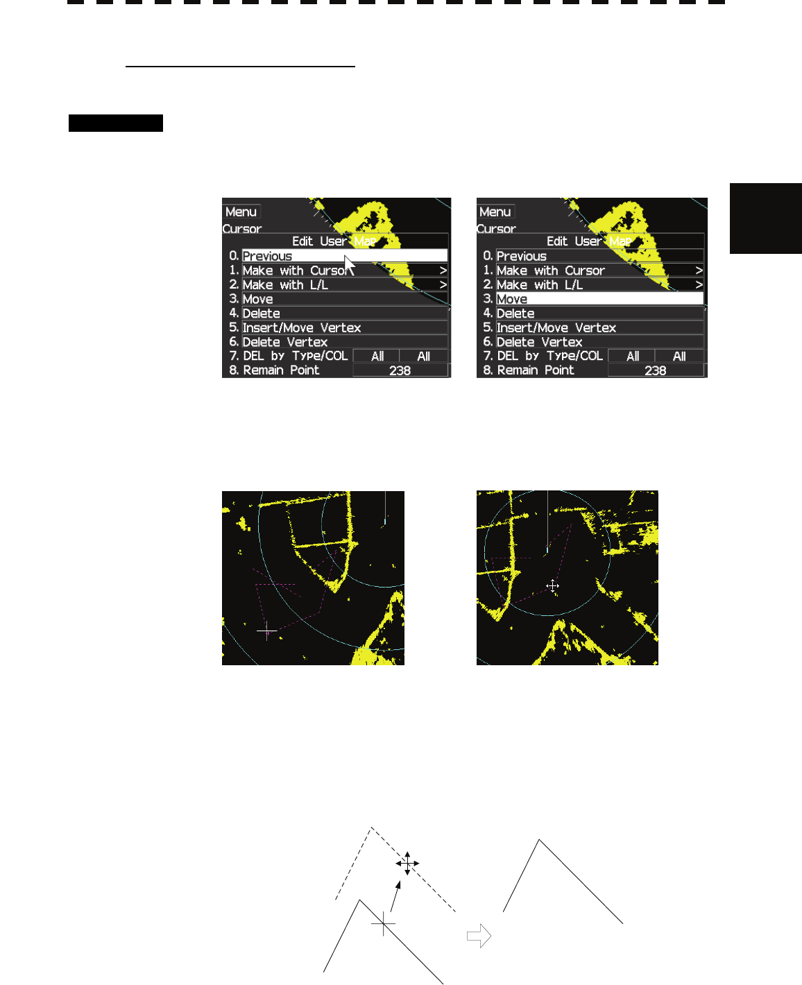
Clearing mark / line data (Clear Mark / Line Data)
The mark / line data saved in the process unit is cleared.
Procedures 1 Press [MENU] key.
Select 8.Next and press [ENTER] key.
Select 4.NAV Information and press [ENTER] key.
Select 1.Edit User Map and press [ENTER] key.
Select 4.Delete and press [ENTER] key.
2 Put the cursor on a location where you want to delete line or mark and
press [ENTER] key.
Confirmation Window will appear.
3 Select 1.Yes and press [ENTER] key.
The mark / line data is deleted.
3-46
3
3.6 DISAPLAY USER MAP y
y y
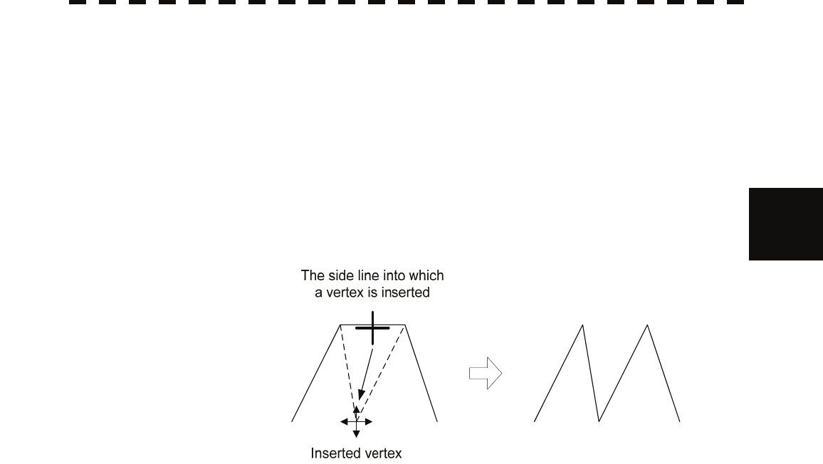
Moving a mark or line (Move)
With regard to the created user map, a mark or line is moved individually.
Procedures 1 Presse [MENU] key.
Select 8.Next and press [ENTER] key.
Select 4.NAV Information and press [ENTER] key.
Select 1.Edit User Map and press [ENTER] key.
2 Select 3.Move and press [ENTER] key.
The user map move mode is selected.
3 Put the cursor on a mark or line, and press [ENTER] key.
When a mark or line to be moved is selected, the cross cursor mark will appear.
4 Move the cursor mark to the destination, and press [ENTER] key.
The selected mark or line is moved to the destination.
To move another mark or line, repeat procedures 3 and 4.
5 When finished with the correction of lines and marks, press [MENU] key.
The cursor mode changes to the normal operation mode, terminating the user map move
mode.
(Example)

3-47
Deleting a mark or line (Delete)
With regard to the created user map, a mark or line is deleted individually.
Procedures 1 Press [MENU] key.
Select 8.Next and press [ENTER] key.
Select 4.NAV Information and press [ENTER] key.
Select 1.Edit User Map and press [ENTER] key.
2 Select 4.Delete and press [ENTER] key.
The user map delete mode is selected.
3 Put the cursor on a mark or line, and press [ENTER] key.
The selected mark or line is deleted.
To delete another mark or line, repeat procedures 3.
4 When finished with the correction of lines and marks, press [MENU] key.
The cursor mode changes to the normal operation mode, terminating the user map delete
mode.
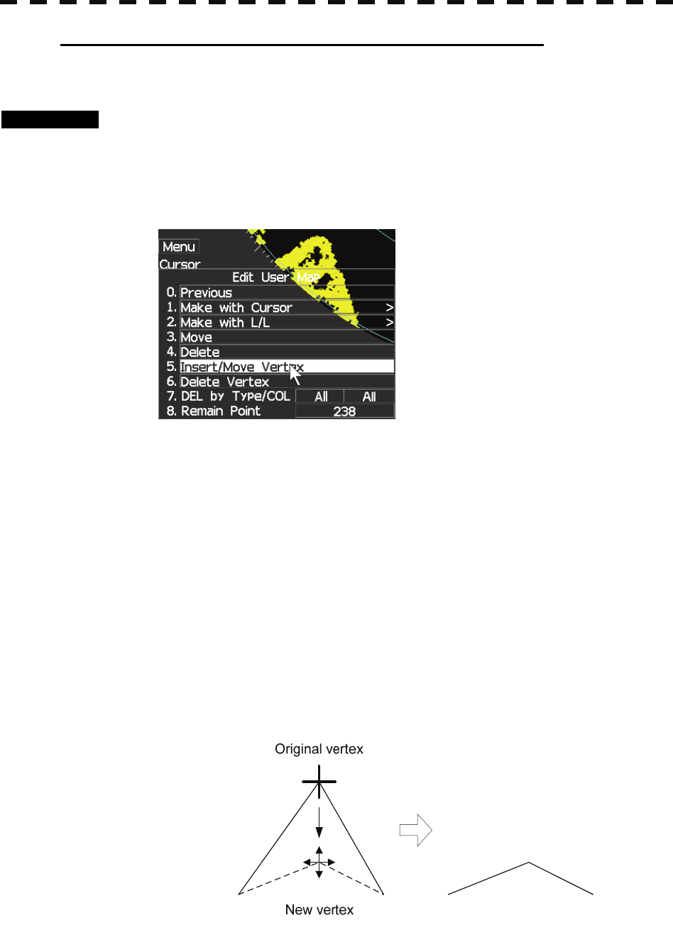
Inserting a vertex into a line (Insert / Move Vertex)
With regard to the created user map, a vertex is inserted into a line.
Procedures 1 Press the [MENU] key.
Select 8.Next and press [ENTER] key.
Select 4.NAV Information and press [ENTER] key.
Select 1.Edit User Map and press [ENTER] key.
2 Select 5.Insert/Map Vertex and press [ENTER] key.
The user map insert / move mode is selected.
3 Put the cursor to a side line into which a vertex will be inserted, and
press the [ENTER] key.
A vertex is inserted into the selected line, and the cross cursor mark will be displayed.
3-48
3
3.6 DISAPLAY USER MAP y
y y
4 Move the cross cursor mark to the newly inserted vertex, and press
[ENTER] key.
To insert another vertex, repeat procedures 3 and 4.
5 When finished with the insertion of all vertices, press [MENU] key.
The cursor mode changes to the normal operation mode, terminating the user map insert /
move mode.
(Example)
3-49
Correcting the mark or vertex of a line (Insert / Move Vertex)
With regard to the created user map, a mark or line is corrected.
Procedures 1 Press [MENU] key.
Select 8.Next and press [ENTER] key.
Select 4.NAV Information and press [ENTER] key.
Select 1.Edit User Map and press [ENTER] key.
2 Select 5.Insert /Move Vertex and press [ENTER]key.
The user map insert / move mode is selected.
3 Put the cursor on the mark or vertex of a line, and press [ENTER] key.
When the mark or vertex of a line to be corrected is selected, the cross cursor mark will
appear.
4 Move the cross cursor mark to the destination, and press [ENTER] key.
The vertex of the selected mark or vertex of a line is moved to the destination.
To correct another mark or vertex of a line, repeat procedures 3 and 4.
5 When finished with the correction of all vertices, press [MENU] key.
The cursor mode changes to the normal operation mode, terminating the user map insert /
move mode.
(Example)
3-50
3
3.6 DISAPLAY USER MAP y
y y
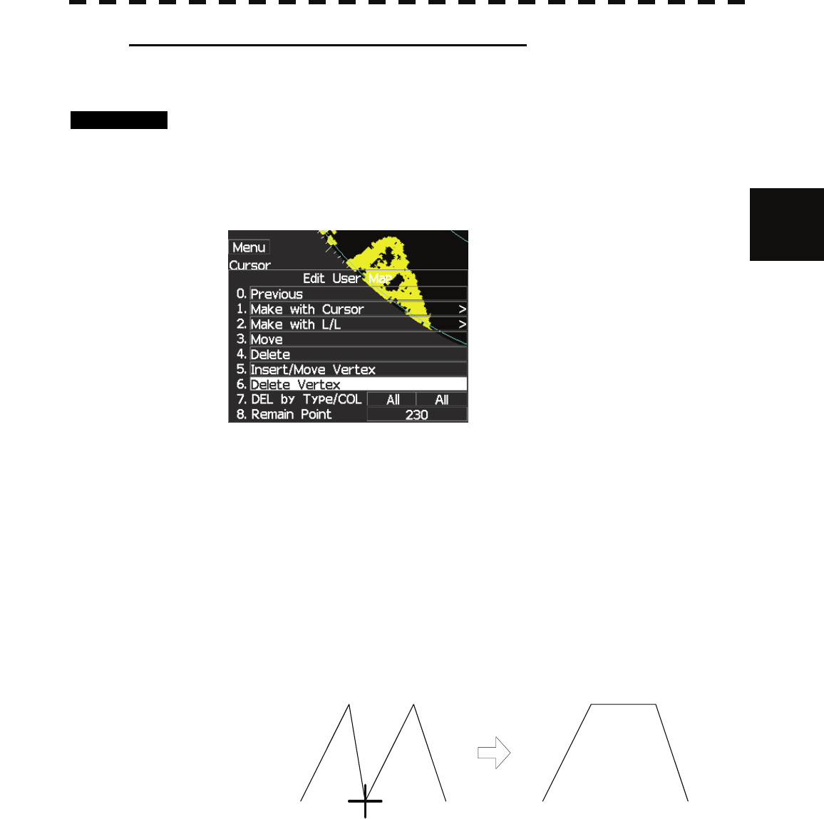
Deleting a mark or vertex of a line (Delete Vertex)
With regard to the created user map, a vertex is deleted individually from a mark or line.
Procedures 1 Press [MENU] key.
Select 8.Next and press [ENTER] key.
Select 4.NAV Information and press [ENTER] key.
Select 1.Edit User Map and press [ENTER] key.
2 Select 6.Delete Vertex.
The user map delete mode is selected.
3 Put the cursor on the mark or vertex of a line, and press [ENTER] key.
The vertex of the selected mark or vertex of a line is deleted.
All of the lines drawn by joining two points are deleted.
To delete another mark or vertex of a or line, repeat procedure 3.
4 When finished with the correction of all vertices, press [MENU] key.
The cursor mode changes to the normal operation mode, terminating the user map delete
mode.
(Example)
The vertex to be deleted
3-51
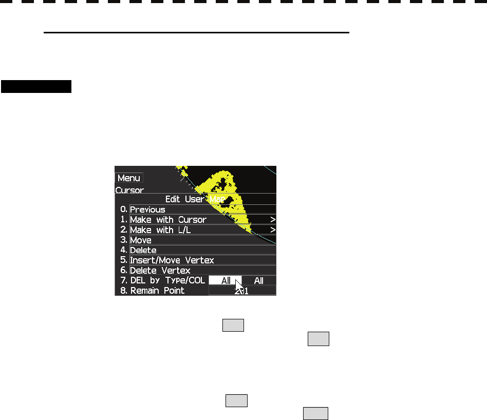
Batch clearing marks or lines (Clear by Type / Color)
With regard to the created user map, marks or lines are batch cleared by type or by color.
Procedures 1 Press [MENU] key.
Select 8.Next and press [ENTER] key.
Select 4.NAV Information and press [ENTER] key.
Select 1.Edit User Map and press [ENTER] key.
2 Select 7.Del by Type/Col and press [ENTER] key.
Select the type of marks or lines to be deleted.
To select all types, select All .
For example, to delete "red ○" marks, select ○ .
3 Select the color of the marks or lines to be deleted.
Select the color of marks or lines to be deleted.
To select all colors, select All .
For example, to clear "red ○" marks, select Red .
After the items have been selected, Confirmation Window will appear.
4 Press [ENTER] key.
Selected marks or lines will be batch cleared.
Note: If data is not copied on the flash memory card (option), the data is not be reloaded.
3-52
3
3.6 DISAPLAY USER MAP y
y y
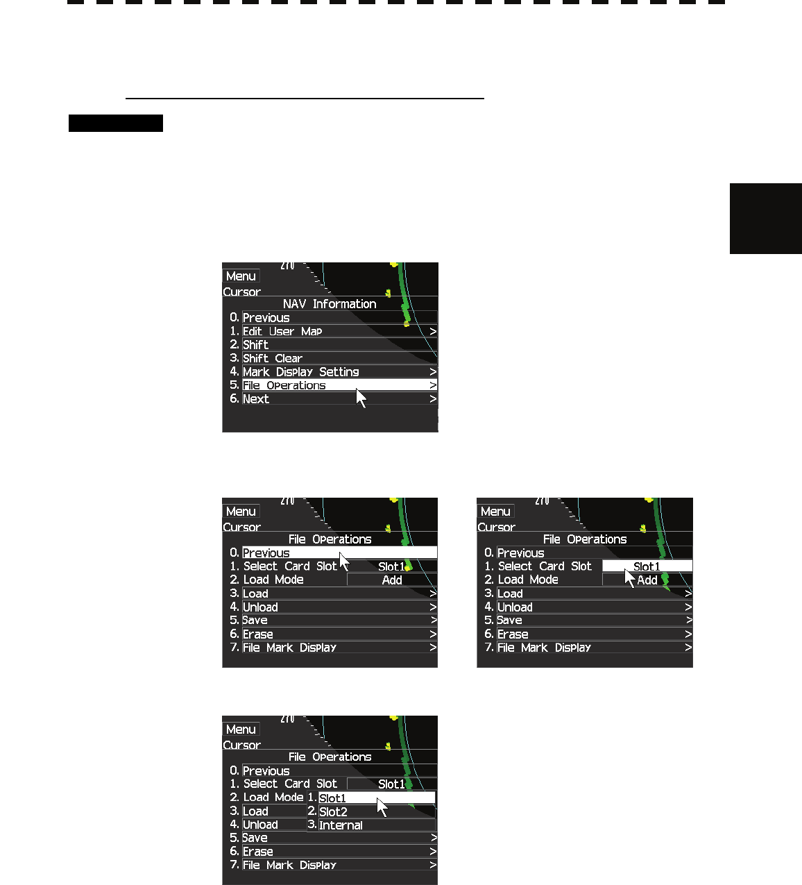
3.6.5 Operate User Map File (File Operations)
[I] Loading navigation data (Load User Map)
Procedures 1 Insert a flash memory card into the card slot.
Flash memory card (option) is necessary.
2 Press [MENU] key.
Select 8.Next and press [ENTER] key.
Select 4.NAV Information and press [ENTER] key.
Select 5.File Operations and press [ENTER] key.
3 Select Card Slot.
Select 1.Select Card Slot and press [ENTER] key.
4 Select 1.Slot1 and press [ENTER] key. (In case of memory card is slot1).
Slot1 and Slot2 Internal of the Select Card Slot items are switched.
3-53
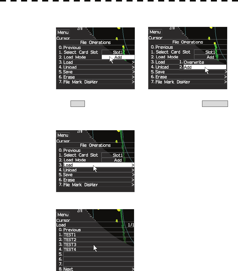
5 Select Add or Overwrite and press [ENTER] key.
Add and Overwrite of the Load Mode items are switched.
When Add is selected, new data is added to the saved data. When Overwrite is
selected, the saved data is overwritten.
6 Select 3.Load and press [ENTER] key.
The list of navigation data saved in the system will be displayed.
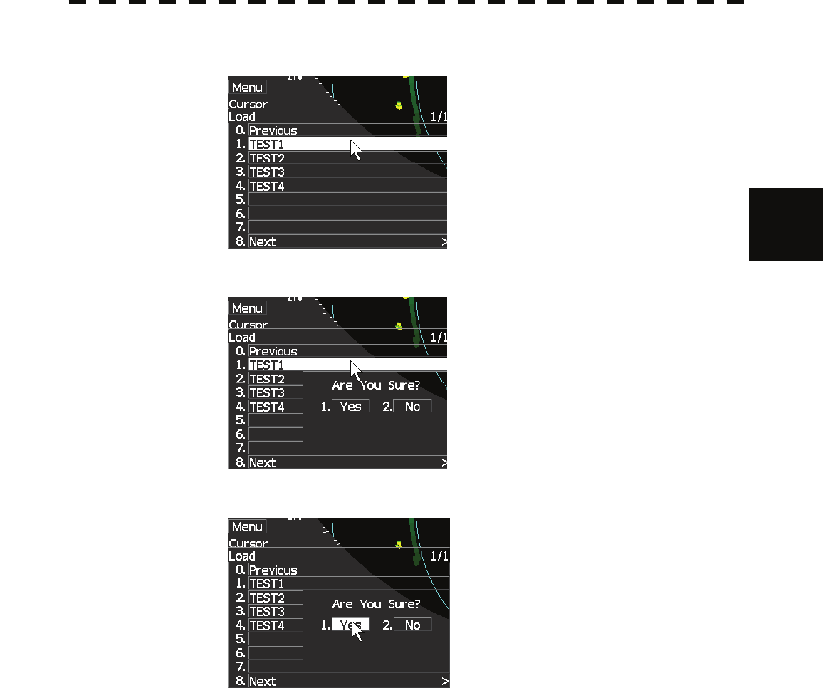
3-54
3
3.6 DISAPLAY USER MAP y
y y
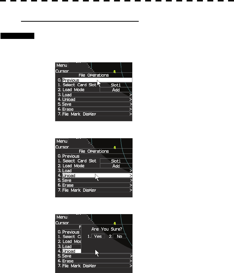
7 Select numeric icon corresponding to the file to be loaded.
Confirmation Window will appear.
8 Select 1.Yes and press [ENTER] key.
The selected navigation data will be loaded and displayed of the display.
3-55
[II] Discarding navigation data (Unload ).
Procedures 1 Press [MENU] key.
Select 8.Next and press [ENTER] key.
Select 4.NAV Information and press [ENTER] key.
Select 5.File Operations and press [ENTER] key.
2 Select 4.Unload and press [ENTER] key.
Unload Confirmation Window will appear.
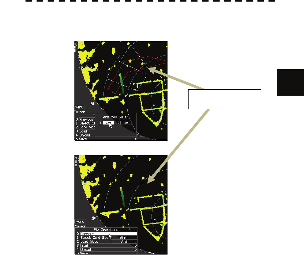
3-56
3
3.6 DISAPLAY USER MAP y
y y
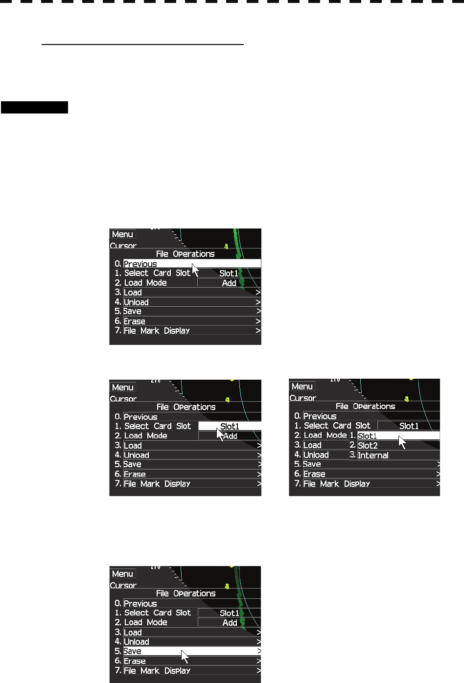
3 Select 1.Yes and press [ENTER] key.
The navigation line and mark will be disappeared.
Unloaded the navigation
line s and marks.
3-57
[III] Saving navigation data (Save ).
Navigation data can be saved when navigation equipment is connected, or the own ship
position on the user map is entered in the manual mode.
Procedures 1 Insert a flash memory card into the card slot.
Flash memory card (option) is necessary.
For the insertion and removal of the card, see HOW TO INSERT AND REMOVE A
CARD in the appendix.
2 Press [MENU] key.
Select 8.Next and press [ENTER] key.
Select 4.NAV Information and press [ENTER] key.
Select 5.File Operations and press [ENTER] key.
3 Select Card Slot.
4 Select Card Slot and press [ENTER] key.
Slot1 and Slot2 Internal of the Select Card Slot items are switched.
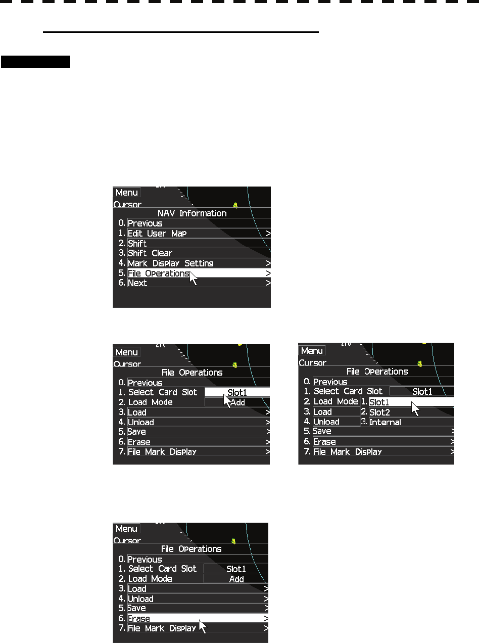
5 Select 5.Save and press [ENTER] key.
3-58
3
3.6 DISAPLAY USER MAP y
y y
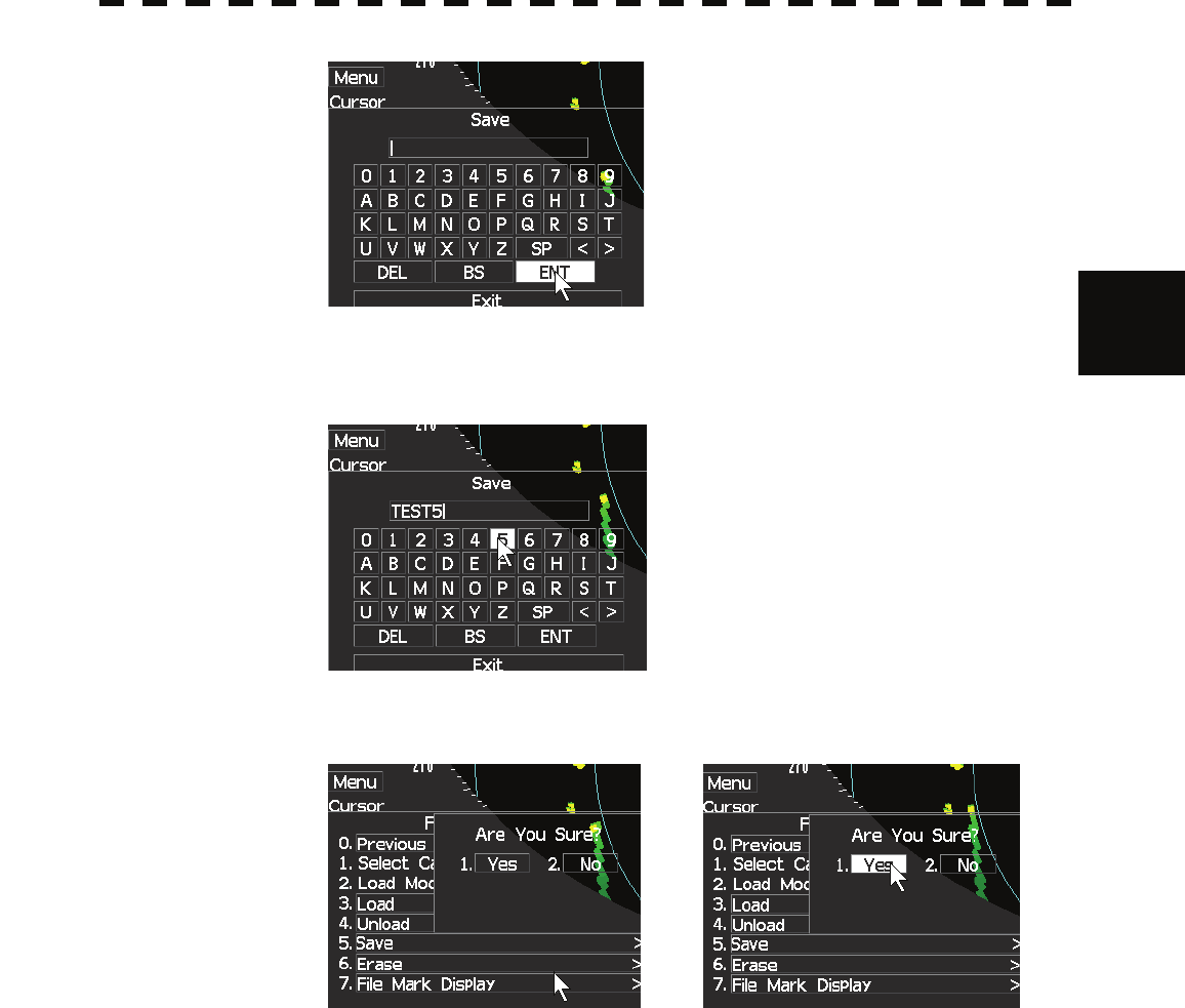
The Input File Name menu will appear.
6 Enter the file name to be saved.
Up to 10 characters can be entered.
After the data has been entered, Confirmation Window will appear.
7 Press [ENTER] key.
Navigation data currently being displayed is saved.
3-59
[IV] Clearing the saved navigation data (Erase)
Procedures 1 Insert a flash memory card into the card slot.
Flash memory card (option) is necessary.
For the insertion and removal of the card, see HOW TO INSERT AND REMOVE A
CARD in the appendix.
2 Press [MENU] key.
Select 8.Next and press [ENTER] key.
Select 4.NAV Information and press [ENTER] key.
Select 5.File Operations and press [ENTER] key.
3 Select Card Slot and press [ENTER] key.
Slot1 and Slot2 of the Select Card Slot items are switched.
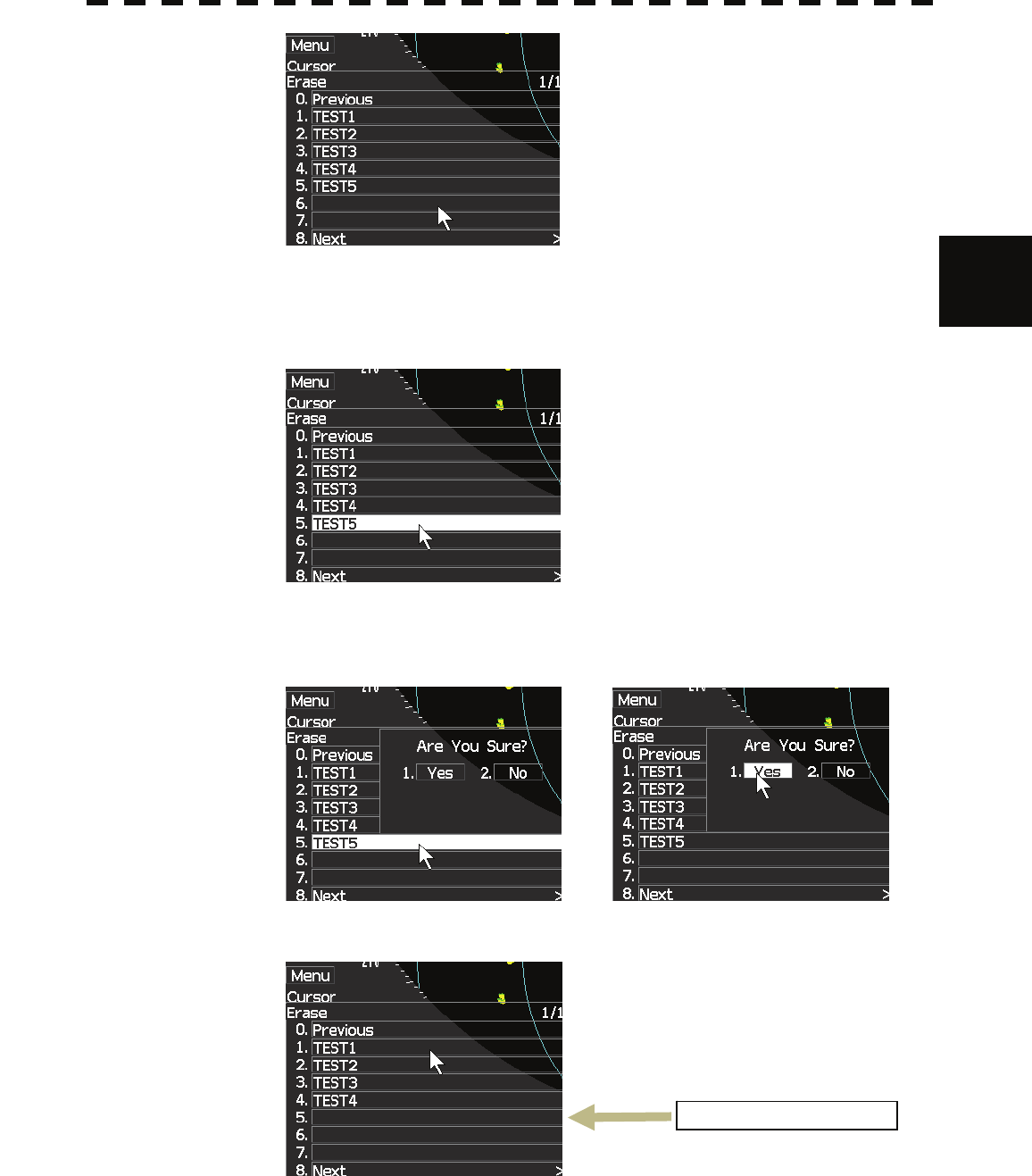
4 Select 6.Erase and press [ENTER] key.
3-60
3
3.6 DISAPLAY USER MAP y
y y
The Erase screen will appear.
The list of navigation data saved in the card will be displayed.
5 Select the number of the file to be erased and press [ENTER]key.
Confirmation Window will appear.
6 Select 1.Yes and press [ENTER] key.
The selected navigation data is erased and the name of the file is deleted from the list.
TEST5 was deleted.
3-61
[V] Displaying saved navigation data (File Mark Display)
Procedures 1 Insert a flash memory card into the card slot.
Flash memory card (option) is necessary.
For the insertion and removal of the card, see HOW TO INSERT AND REMOVE A
CARD in the appendix.
2 Press [MENU] key.
Select 8.Next and press [ENTER] key.
Select 4.NAV Information and press [ENTER] key.
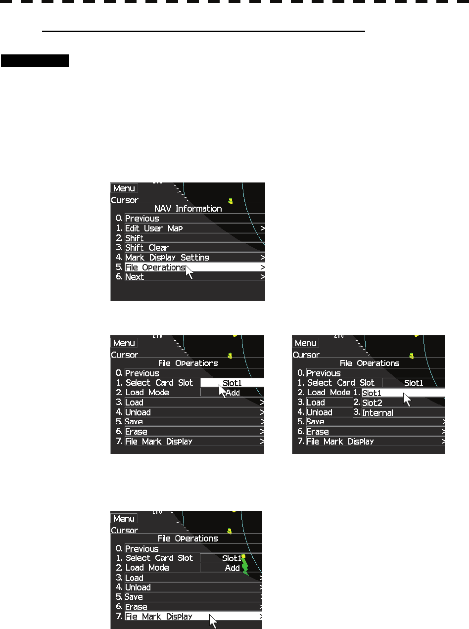
Select 5.File Operations and press [ENTER] key.
3 Select Card Slot and press [ENTER] key.
Slot1 and Slot2 of the Select Card Slot items are switched.
4 Select 7.File Mark Display and press [ENTER] key.
The Card Mark Display menu will appear.

3-62
3
3.6 DISAPLAY USER MAP y
y y
The list of navigation data saved in the card will be displayed.
3-63
3.7 SCREEN CAPTURE
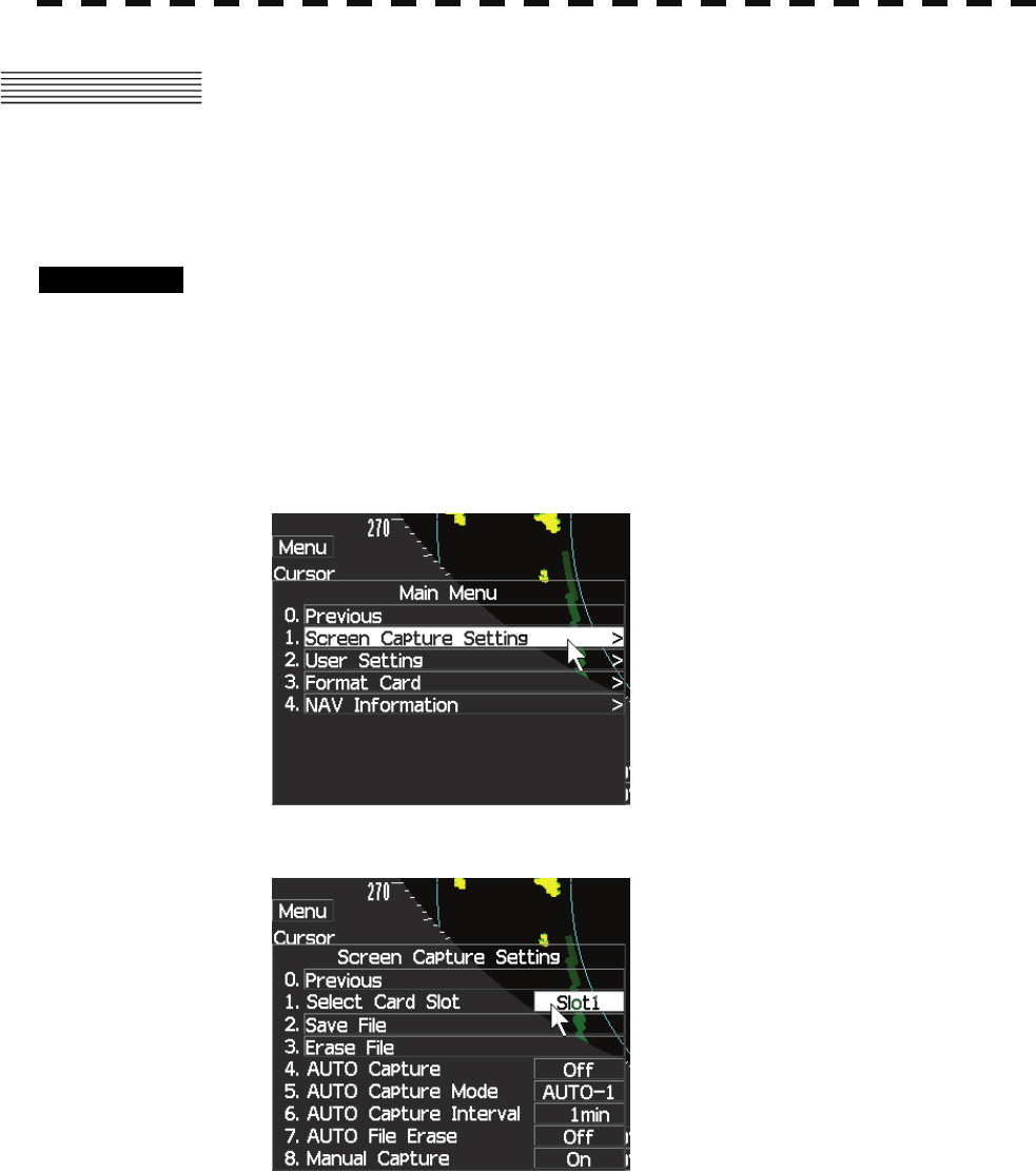
3.7.1 SCREEN CAPTURE SETTING (Select Card Slot).
Procedures 1 Insert a flash memory card into the card slot.
Flash memory card (option) is necessary.
For the insertion and removal of the card, see HOW TO INSERT AND REMOVE A
CARD in the appendix.
2 Press [MENU] key.
Select 8.Next and press [ENTER] key.
Select 1.Screen Capture Setting and press [ENTER] key.
3 Select Card Slot and press [ENTER] key.

3-64
3
3.7 SCREEN CAPTURE y
y y
Slot1 and Slot2 of the Select Card Slot items are switched.
4 Select 1.Slot1 or 2.Slot2 and press [ENTER] key.
3-65
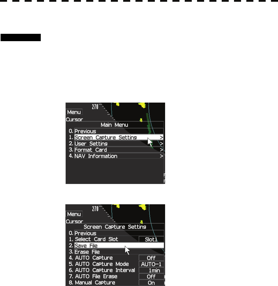
3.7.2 SCREEN CAPTURE SETTING (SAVE FILE).
Procedures 1 Insert a flash memory card into the card slot.
Flash memory card (option) is necessary.
For the insertion and removal of the card, see HOW TO INSERT AND REMOVE A
CARD in the appendix.
2 Press [MENU] key.
Select 8.Next and press [ENTER] key.
Select 1.Screen Capture Setting and press [ENTER] key.
3 Select 2.Save File and press [ENTER] key.
3-66
3
3.7 SCREEN CAPTURE y
y y
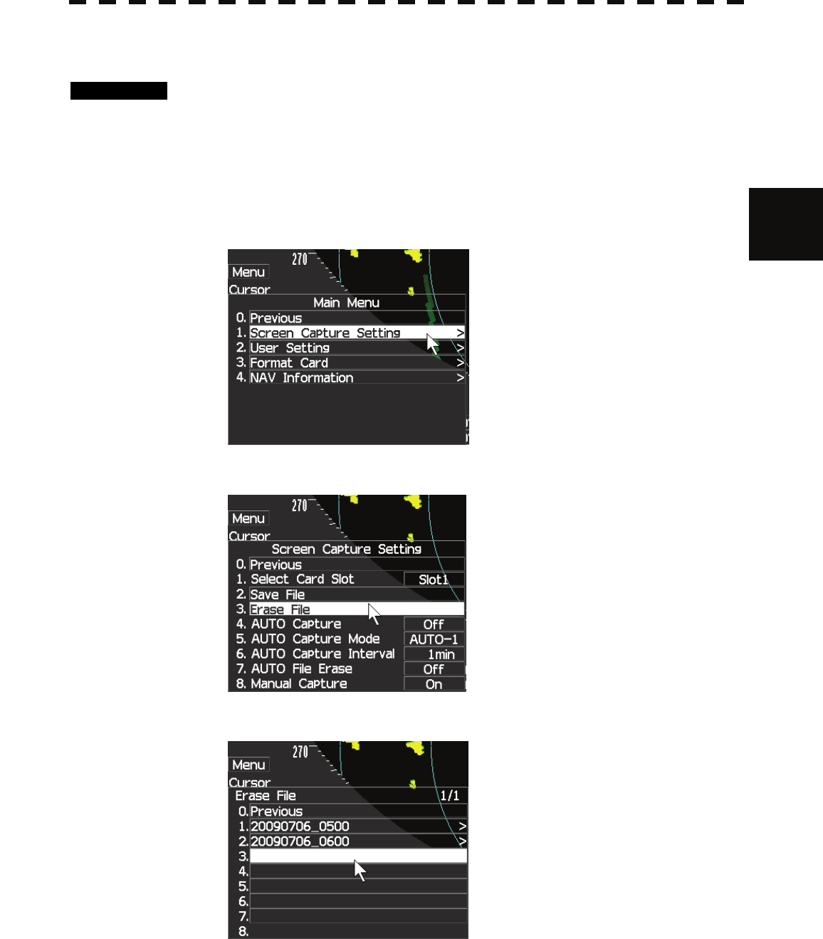
3.7.3 SCREEN CAPTURE SETTING (Erase File).
Procedures 1 Insert a flash memory card into the card slot.
Flash memory card (option) is necessary.
For the insertion and removal of the card, see HOW TO INSERT AND REMOVE A
CARD in the appendix.
2 Press [MENU] key.
Select 8.Next and press [ENTER] key.
Select 1.Screen Capture Setting and press [ENTER] key.
3 Select 3.Elase File and press [ENTER] key.
4 Select erasing file and press [ENTER] key.
3-67
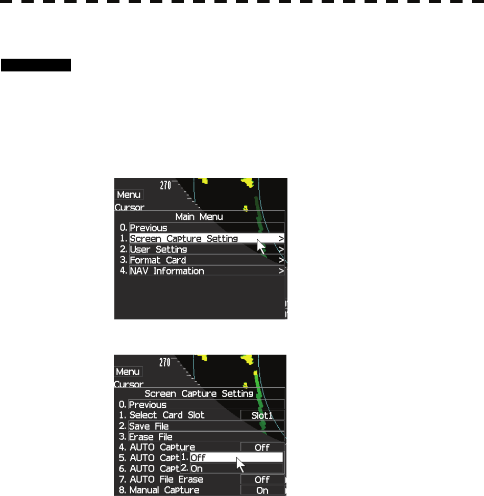
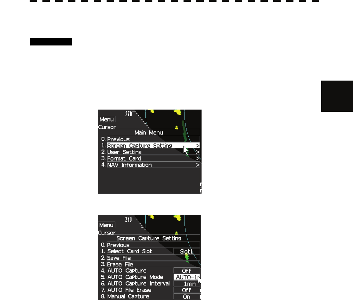
3.7.4 SCREEN CAPTURE SETTING (AUTO Capture).
Procedures 1 Insert a flash memory card into the card slot.
Flash memory card (option) is necessary.
For the insertion and removal of the card, see HOW TO INSERT AND REMOVE A
CARD in the appendix.
2 Press [MENU] key.
Select 8.Next and press [ENTER] key.
Select 1.Screen Capture Setting and press [ENTER] key.
3 Select 4.AUTO Capture and press [ENTER] key.
4 Select off or on and press [ENTER] key.
3-68
3
3.7 SCREEN CAPTURE y
y y
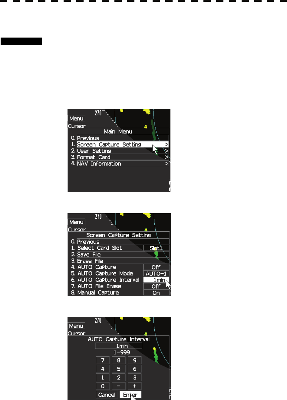
3.7.5 SCREEN CAPTURE SETTING (AUTO Capture Mode).
Procedures 1 Insert a flash memory card into the card slot.
Flash memory card (option) is necessary.
For the insertion and removal of the card, see HOW TO INSERT AND REMOVE A
CARD in the appendix.
2 Press [MENU] key.
Select 8.Next and press [ENTER] key.
Select 1.Screen Capture Setting and press [ENTER] key.
3 Select 5.AUTO Capture Mode and press [ENTER] key.
4 Select AUTO-1 or AUTO-2 and press [ENTER] key.
3-69
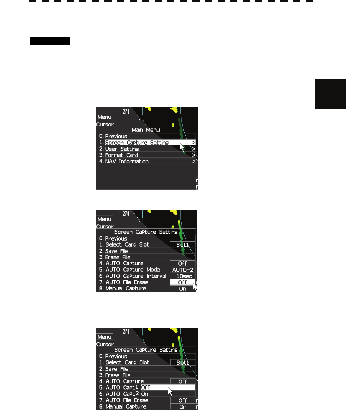
3.7.6 SCREEN CAPTURE SETTING (AUTO Capture Interval).
Procedures 1 Insert a flash memory card into the card slot.
Flash memory card (option) is necessary.
For the insertion and removal of the card, see HOW TO INSERT AND REMOVE A
CARD in the appendix.
2 Press [MENU] key.
Select 8.Next and press [ENTER] key.
Select 1.Screen Capture Setting and press [ENTER] key.
3 Select 6.AUTO Capture Interval and press [ENTER] key.
4 Input interval time and press [ENTER] key.
3-70
3
3.7 SCREEN CAPTURE y
y y
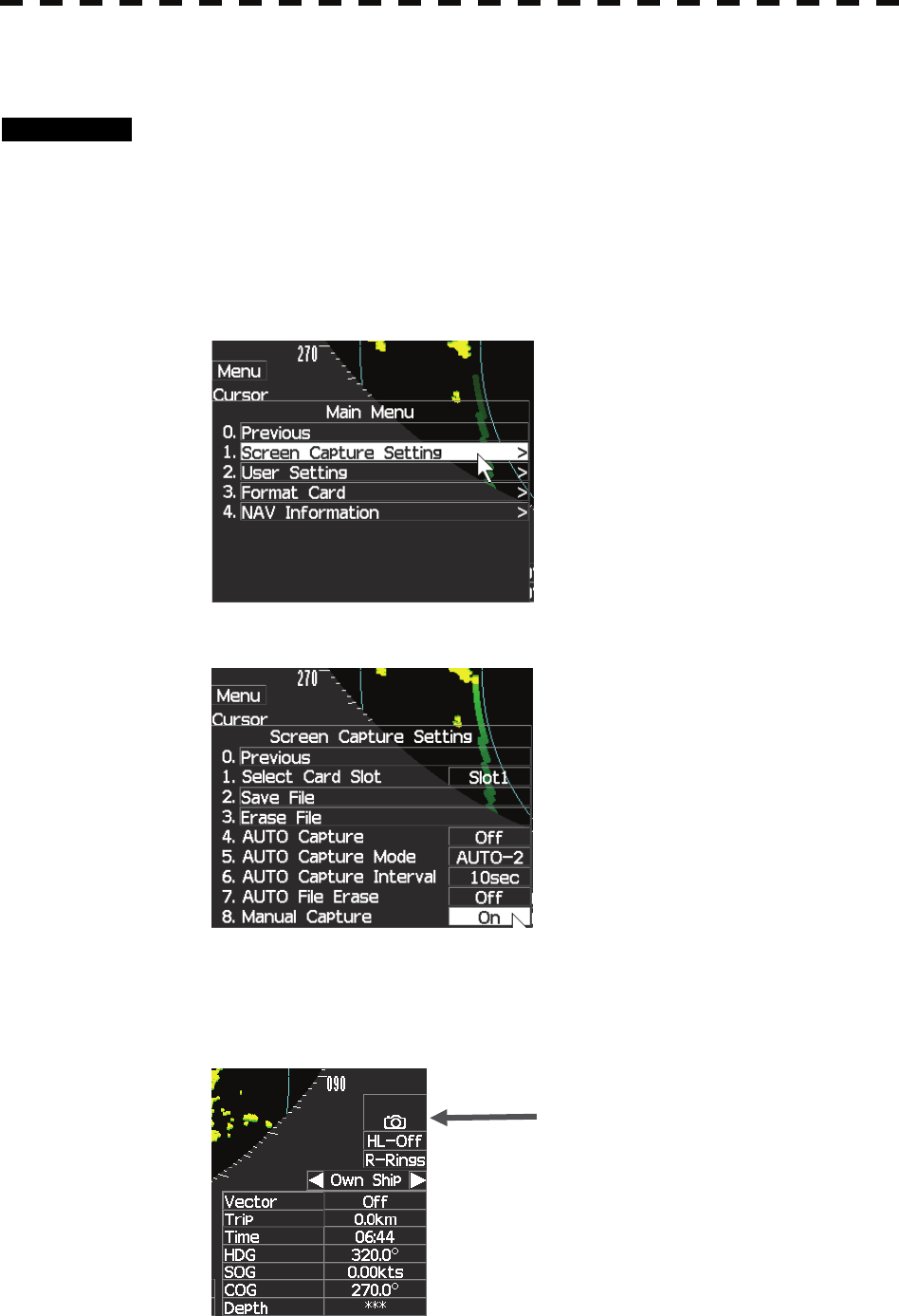
3.7.7 SCREEN CAPTURE SETTING (AUTO File Erase).
Procedures 1 Insert a flash memory card into the card slot.
Flash memory card (option) is necessary.
For the insertion and removal of the card, see HOW TO INSERT AND REMOVE A
CARD in the appendix.
2 Press [MENU] key.
Select 8.Next and press [ENTER] key.
Select 1.Screen Capture Setting and press [ENTER] key.
3 Select 7.AUTO File Erase and press [ENTER] key.
4 Select off or on and press [ENTER] key.
off : no empty card can’t save new file.
on: old file is elased automaticaly.
3-71
3.7.8 SCREEN CAPTURE SETTING (Manual Capture).
Procedures 1 Insert a flash memory card into the card slot.
Flash memory card (option) is necessary.
For the insertion and removal of the card, see HOW TO INSERT AND REMOVE A
CARD in the appendix.
2 Press [MENU] key.
Select 8.Next and press [ENTER] key.
Select 1.Screen Capture Setting and press [ENTER] key.
3 Select 8.Manual Capture and press [ENTER] key.
4 Select off or on and press [ENTER] key.
off : no action for pressing capture key.
on: when pressed capture key,screen capture file is downloaded
automatically to the card.
Manual Capture mode
3-72
3
3.8 USER SETTING y
y y
3.8 USER SETTING
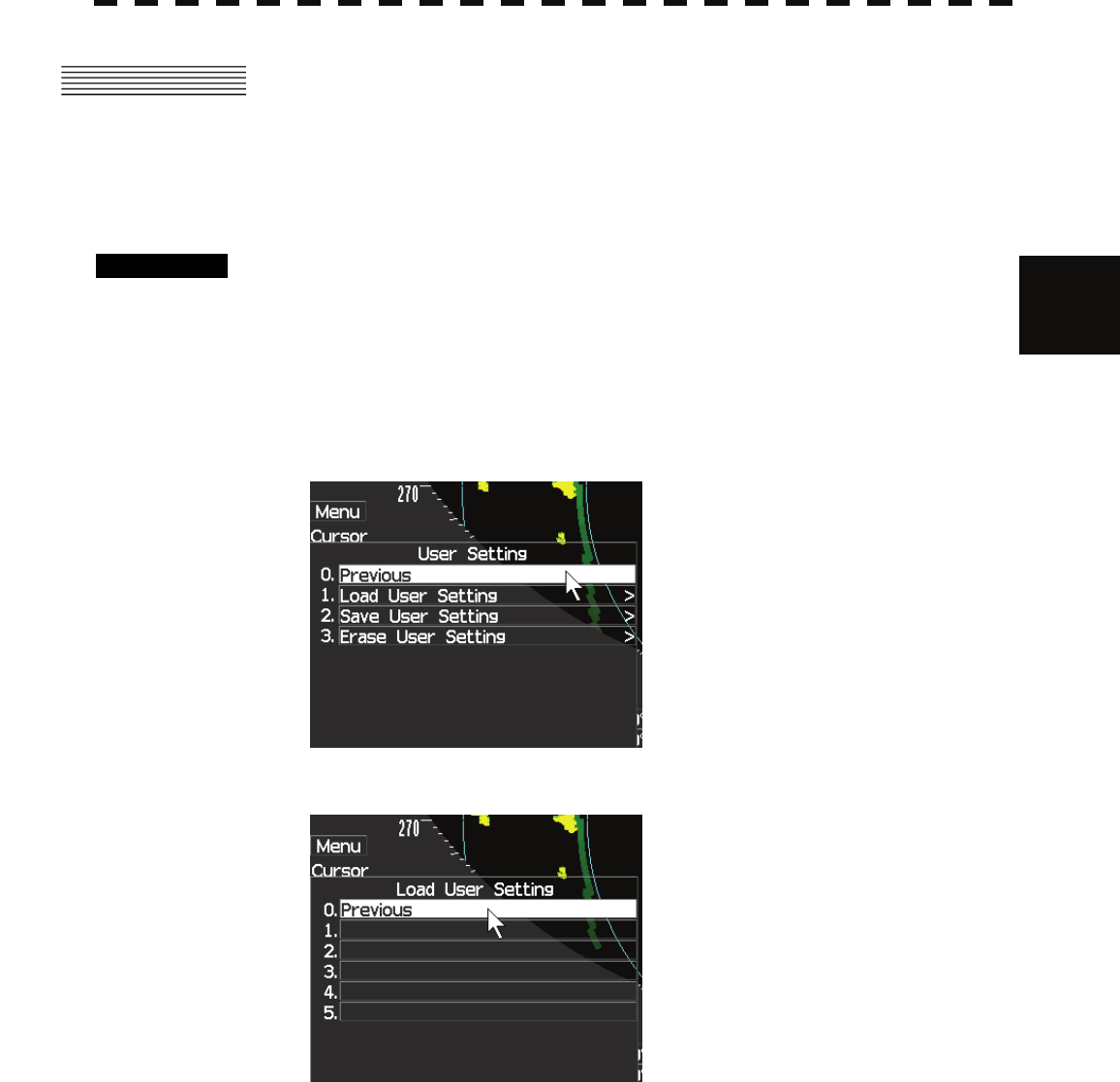
3.8.1 USER SETTING (Load User Setting).
Procedures 1 Insert a flash memory card into the card slot.
Flash memory card (option) is necessary.
For the insertion and removal of the card, see HOW TO INSERT AND REMOVE A
CARD in the appendix.
2 Press [MENU] key.
Select 8.Next and press [ENTER] key.
Select 2.User Setting and press [ENTER] key.
3 Select 1.Load User Setting and press [ENTER] key.
4 Select user setting file and press [ENTER] key.
3-73
3.8.2 USER SETTING (Save User Setting).
Procedures 1 Insert a flash memory card into the card slot.
Flash memory card (option) is necessary.
For the insertion and removal of the card, see HOW TO INSERT AND REMOVE A
CARD in the appendix.
2 Press [MENU] key.
Select 8.Next and press [ENTER] key.
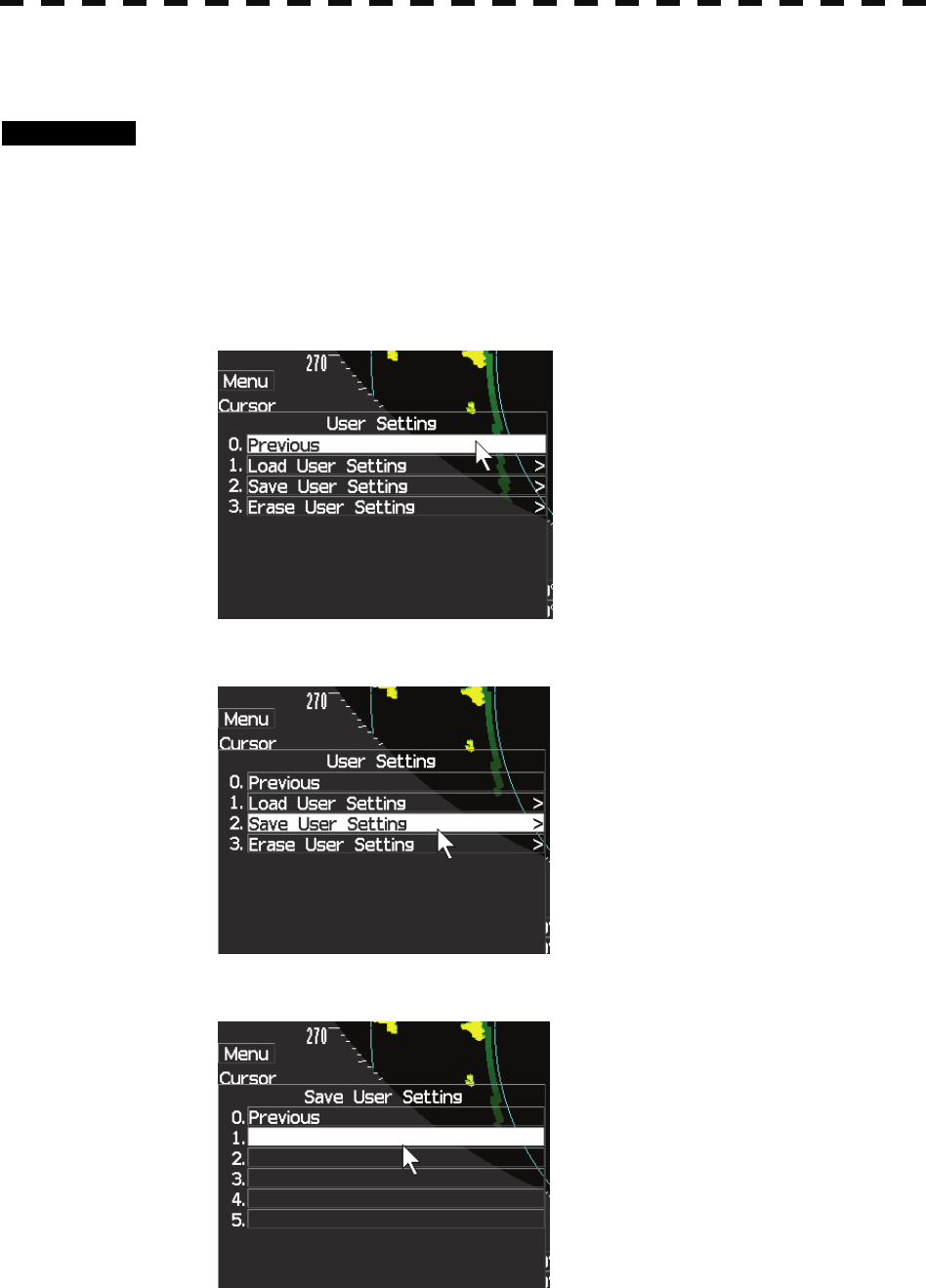
Select 2.User Setting and press [ENTER] key.
3 Select 2.Save User Setting and press [ENTER] key.
4 Select user setting file and press [ENTER] key.
3-74
3
3.8 USER SETTING y
y y
3.8.3 USER SETTING (Erase User Setting).
Procedures 1 Insert a flash memory card into the card slot.
Flash memory card (option) is necessary.
For the insertion and removal of the card, see HOW TO INSERT AND REMOVE A
CARD in the appendix.
2 Press [MENU] key.
Select 8.Next and press [ENTER] key.
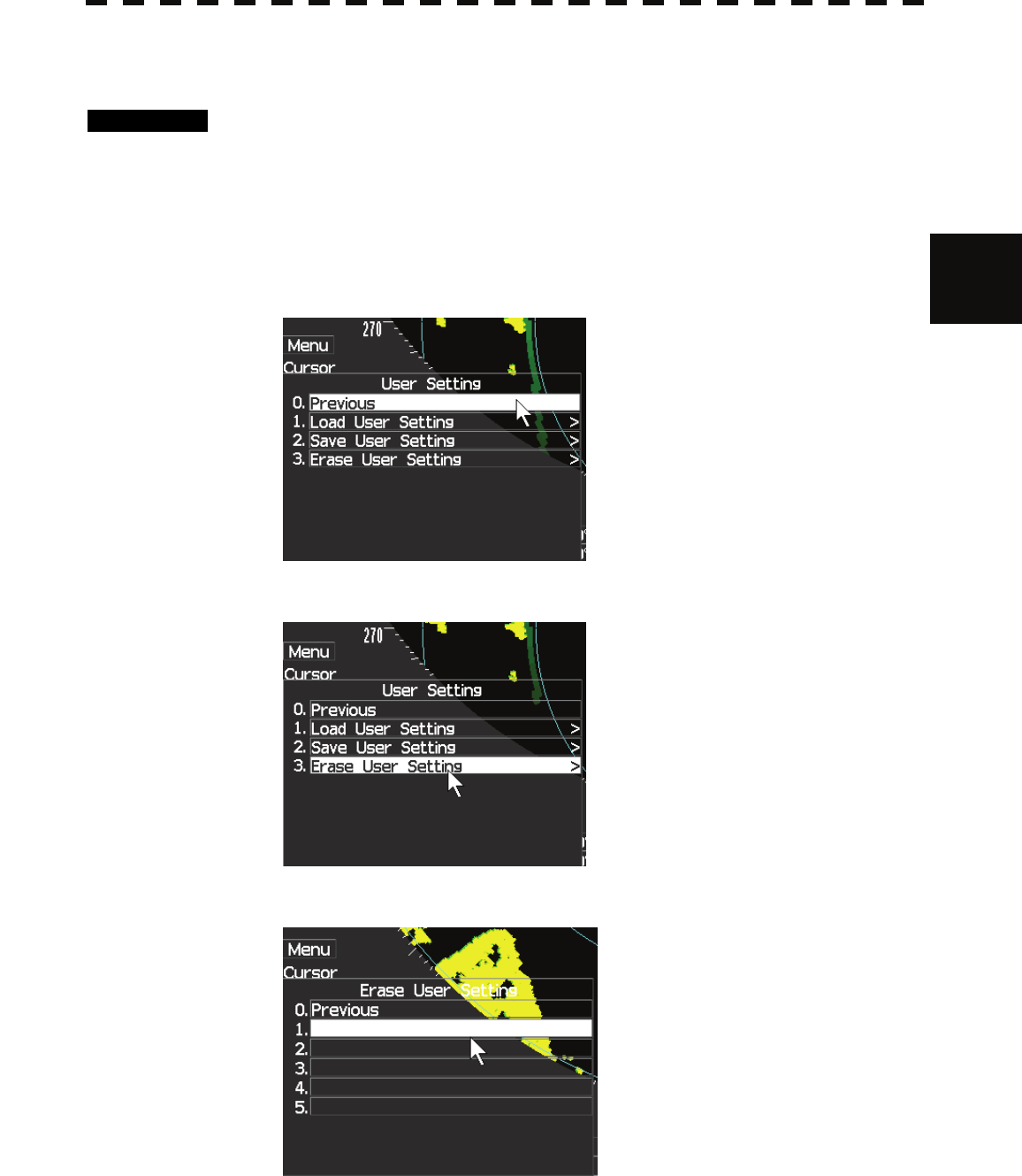
Select 2.User Setting and press [ENTER] key.
3 Select 3.Erase User Setting and press [ENTER] key.
4 Select user erasing file and press [ENTER] key.
3-75
3.9 FORMAT CARD
3.9.1 FORMAT CARD (Select Card Slot).
Procedures 1 Insert a flash memory card into the card slot.
Flash memory card (option) is necessary.
For the insertion and removal of the card, see HOW TO INSERT AND REMOVE A
CARD in the appendix.
2 Press [MENU] key.
Select 8.Next and press [ENTER] key.
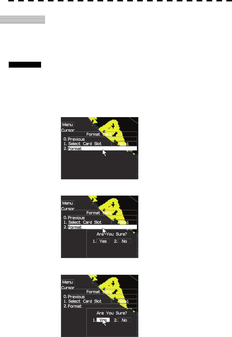
Select 3.Format Card and press [ENTER] key.
Confirmation Window will appear.
3 Select 1.Yes or No and press [ENTER] key.
3-76
3
3.10 AIS FUNCTION y
y y
3.10 AIS FUNCTION
When an AIS transceiver is connected with the radar and also a (D)GPS and heading sensor is connected,
AIS target will been drawn on the screen on the position of this target. Also there will been a name list at
the bottom left and right side of the screen.
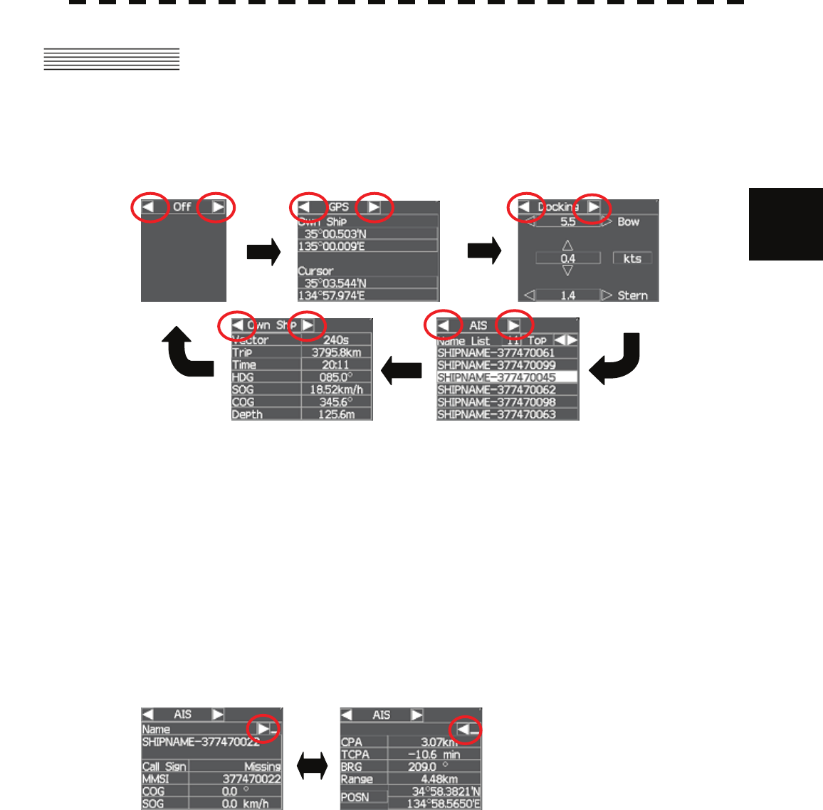
The information in windows at the left and right side bottom can be selected from “OFF”, “GPS”,
“Docking”, “AIS information”, and “Own Ship Data” as follow.
By pressing on the arrow button, the information in window will be changed.
3.10.1 VESSEL NAME LIST
The list is sorted on the distance from the target, the vessel that is on top is the vessel with the smallest
distance from the own vessel. By pressing on the arrow button, the user can scroll through the name list.
When a name is selected in the list, the target will be highlighted on the screen.
3.10.2 VESSEL INFORMATION
When an AIS symbol is selected on the screen, extra information from this vessel will be shown at the
window.
By pressing on the arrow button, the user can change the information.
3-77
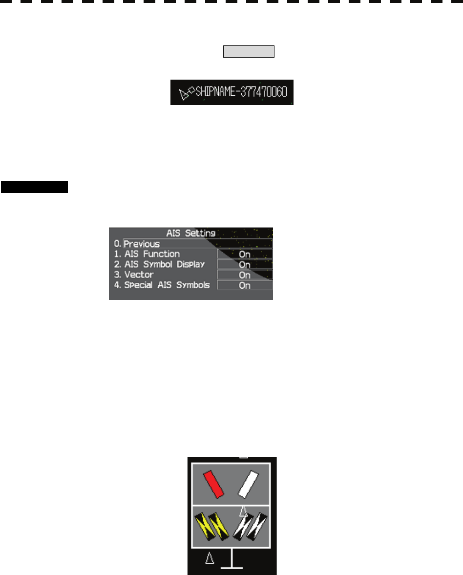
3.10.3 DISPLAY THE VESSEL NAMES ON THE SCREEN
By pressing [AIS LABEL] key or pressing AIS Label at the right top on the screen, the vessel names
will be displayed beside the AIS symbol on the screen.
Example of vessel name displaying
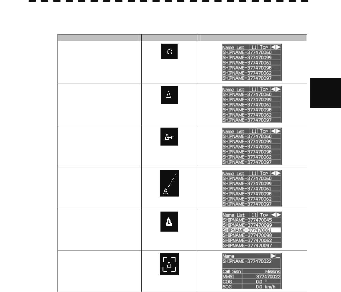
3.10.4 AIS Setting Menu
Procedures 1 Press [MENU] key.
2 Select 4.AIS Setting and press [ENTER] key.
1. AIS Function
On : AIS function is effective.
Off : AIS function is invalid.
2. AIS Symbol Display
On : AIS symbols are displayed on the screen.
Off : AIS symbols are not displayed on the screen.
3. Vector
On : AIS vector is displayed on the screen.
Off : AIS vector is not displayed on the screen.
4. Special AIS Symbols
On : AIS signal symbol is displayed on the screen.
Off : AIS signal symbol is not displayed on the screen.
Example of AIS signal symbol
3-78
3
3.10 AIS FUNCTION y
y y
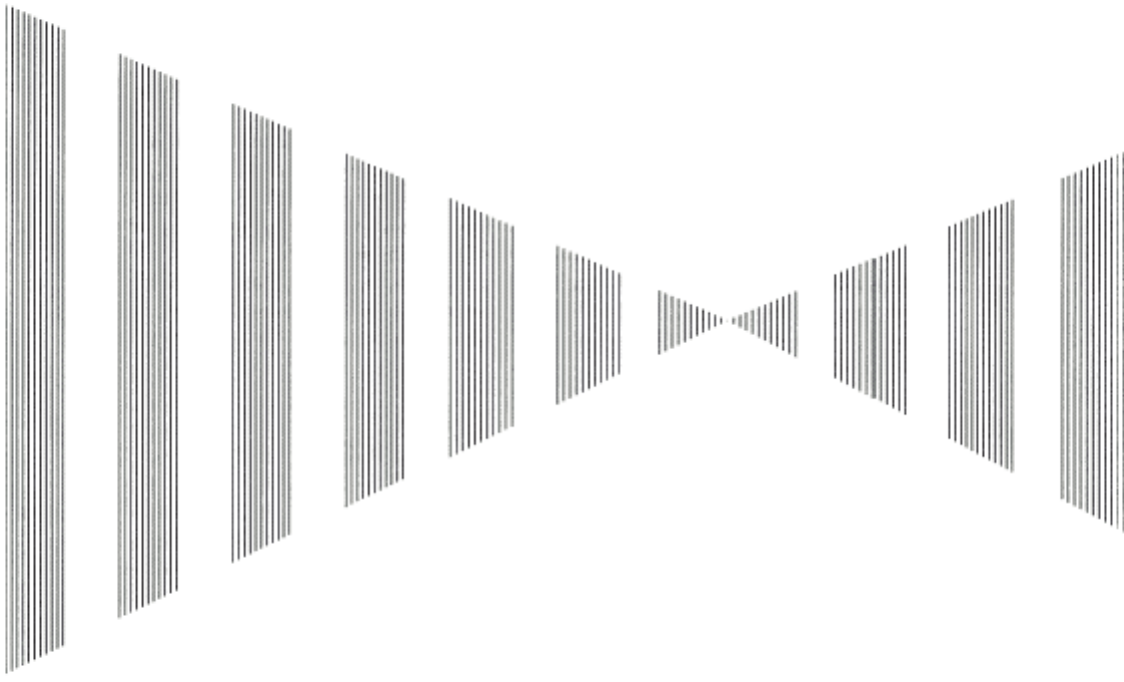
3.10.5 AIS SYMBOL
On the screen, the following symbols can be found:
Description Symbol AIS information window
AIS target without heading
AIS target
AIS target with blue sign
AIS target with speed
AIS target which is selected
in the left or right bottom
side window
AIS target which is selected
on the screen

3-79
SECTION 4
MEASUREMENT OF
RANGE AND BEARING
4.1 MEASUREMENT BY TRACKBALL....... 4-1
4.2 MEASUREMENT BY RANGE RINGS ... 4-2
4.3 MEASUREMENT BY EBLS AND VRMS4-3
4-1
4.1 MEASUREMENT BY TRACKBALL
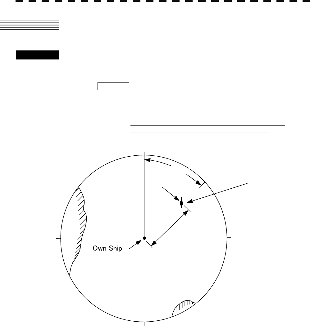
Procedures 1 Check the target echoes on the radar display.
2 Move the cursor mark to a target by the trackball.
The CURSOR on the radar display indicates the bearing and range of the target. The
range is a distance from own ship’s position.
CURSOR
45.0°: True bearing of the cursor relative to own ship
3km: Range between the cursor and own ship
Cursor
3km
Target
180
90
270
0
45°
Figure 4.1

4-2
4
4.2 MEASUREMENT BY RANGE RINGS y
yyy
4.2 MEASUREMENT BY RANGE RINGS
Procedures 1 Press [RR] key.
The Range Rings will appear on the radar display.
The range between the target and own ships can be determined by visually measuring the
target’s position that lies between two range rings.

4-3
4.3 MEASUREMENT BY EBLS AND VRMS
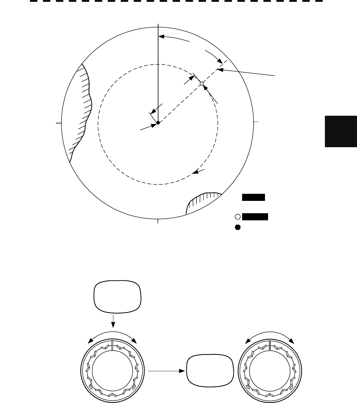
Procedures 1 Press [EBL1/EBL2] key to select EBL1 display and operation.
The EBL1 indication at the lower left of the radar display will be selected and the
EBL1 will appear as a broken-line on the PPI display.
2 Turn the [JOG DIAL] to put EBL1 on a target.
The bearing of the EBL1 will appear at the lower left of the radar display. The EBL1
bearing represents the target’s bearing.
3 Press [VRM1/VRM2] key to select VRM1 display and operation.
The VRM1 indication at the lower right of the radar display will be selected and the
VRM1 will appear as a broken-line circle on the PPI display.
4 Move the broken-line VRM1 to the target by using the [JOG
DIAL] control.
The range of the VRM1 from own ship will appear at the lower right of the radar display.
The range of VRM1 signifies a distance between the target and own ship.
Refer to Figure 4.2 in the next page.
In this Figure 4.2, the range and bearing are;
Range: 3km
Bearing: 45.0°
4-4
4
4.3 MEASUREMENT BY TRACK BALL y
yyy
Figure 4.2
180
90
270
0
45°
3km
Target
Own Ship
VRM1
EBL1
EBL1
VRM1
EBL2
VRM2
45.0°
3 km
km
EBL1/EBL2
EBL Control VRM Control
VRM1/VRM2

4-5

SECTION 5
TRUE AND FALSE ECHOES
ON DISPLAY
5.1 Radar Wave with the Horizon ...........................................5-2
5.2 Strength of Reflection from the Target ............................5-4
5.3 Sea Clutters ........................................................................5-5
5.4 False Echoes ......................................................................5-6
5.5 Display of Radar Transponder (SART) ............................5-9

5-1
The radar operator has a role of interpreting the radar displays to provide his best aid in maneuvering the ship.
For this purpose, the operator has to observe the radar displays after fully understanding the advantages and
disadvantages that the radar has. For better interpretation of radar display, it is important to gain more
experiences by operating the radar equipment in fair weathers and comparing the target ships watched with the
naked eyes and their echoes on the radar display.
The radar is mainly used to monitor the courses of own ship and other ships in open seas, to check buoys and
other nautical marks when entering a port, to measure own ship’s position in the coastal waters relative to the
bearings and ranges of the shore or islands using a chart, and to monitor the position and movement of a heavy
rain if it appears on the radar display.
Various types of radar display will be explained below.
5-2
5.1 RADAR WAVE WITH THE HORIZON yy
yyy
5
5.1 RADAR WAVE WITH THE HORIZON
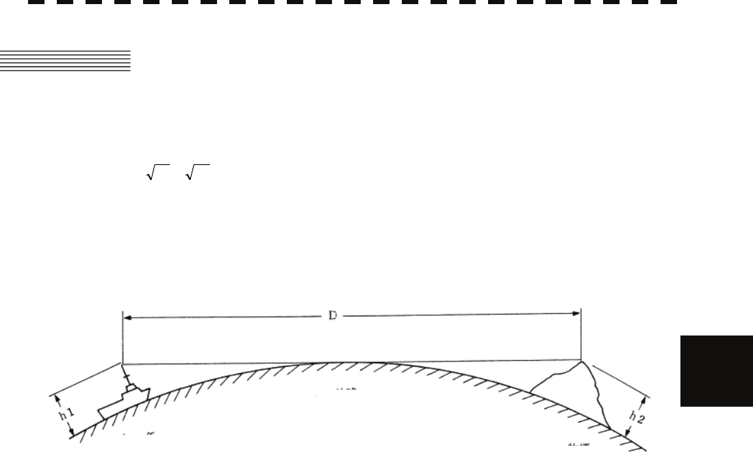
Radar beam radiation has the nature of propagating nearly along the curved surface of the earth.
The propagation varies with the property of the air layer through which the radar beam propagates.
In the normal propagation, the distance (D) of the radar wave to the horizon is approximately 10% longer than
the distance to the optical horizon. The distance (D) is given by the following formula:
D=2.23( h2h1 +)(nm)
h1: Height (m) of radar scanner above sea level
h2: Height (m) of a target above sea level
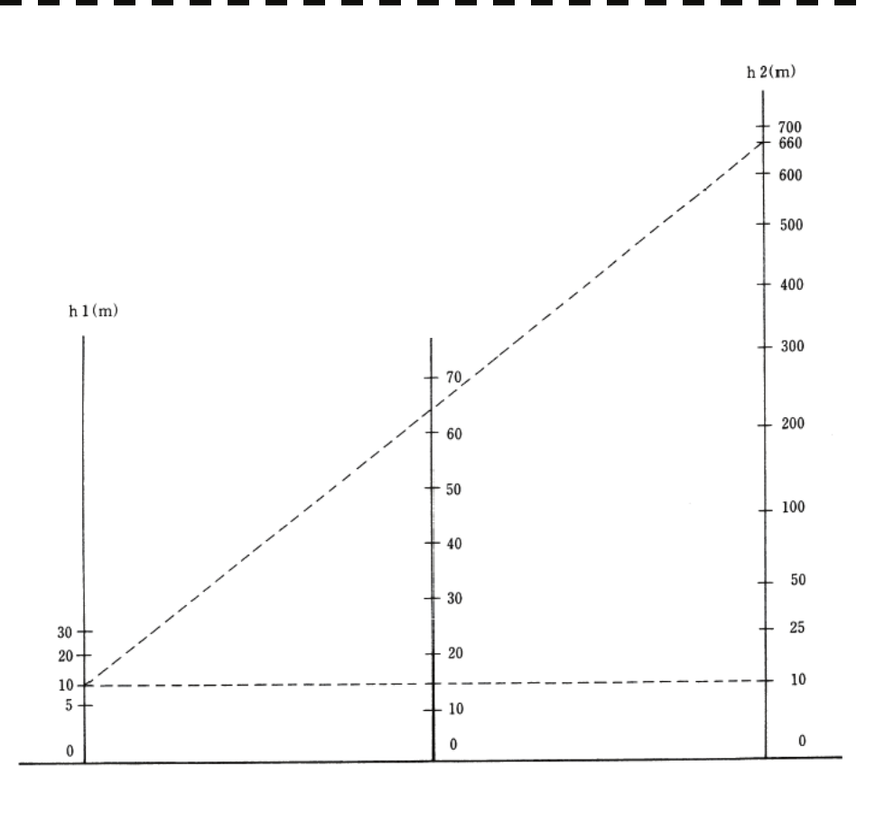
Figure 5. is a diagram for determining the maximum detection range of a target that is limited by the curve of
the earth surface in the normal propagation.
Figure 5.1
Radar
Earth
Targets
5-3
Figure 5.2
When the height of own ship’s scanner is 10 m for instance,
(a) A target that can be detected at the radar range of 64 nm on the radar display is required to have a height
of 660 m or more.
(b) If the height of a target is 10 m, the radar range has to be approx. 15 nm. However, the maximum
radar range at which a target can be detected on the radar display depends upon the size of the target
and the weather conditions, that is, the radar range may increase or decrease depending upon those
conditions.
Height of Radar Scanner Detective Range Height of Target
D (nm)
5-4
5.2 STRENGTH REFLECTION FROM THE TARGET
yy
yyy
5
5.2 STRENGTH OF REFLECTION FROM THE
TARGET
The signal intensity reflected from a target depends not only on the height and size of the target but also on its
material and shape. The echo intensity from a higher and larger target is not always higher in general.
In particular, the echo from a coast line is affected by the geographic conditions of the coast.
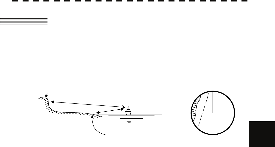
If the coast has a very gentle slop, the echo from a mountain of the inland appears on the radar display.
Therefore, the distance to the coast line should be measured carefully.
HL
Figure 5.3
Quay displayed on the radar display
River side not displayed
on the radar display.

5-5
5.3 SEA CLUTTERS
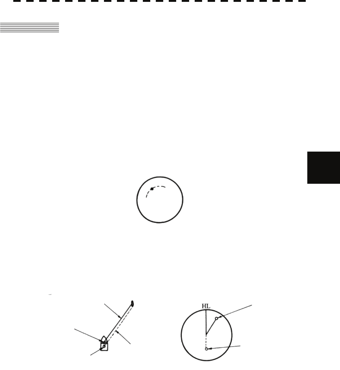
When the sea surface ruffles, bright echo returns spread around the center of the radar display.
The higher the waves are, the echo returns are larger.
Swirling currents may appear as a smooth line like a coastal line.
5-6
5.4 FALSE ECHOES yy
yyy
5
5.4 FALSE ECHOES
The radar observer may be embarrassed with some echoes that do not exist actually. These false echoes
appear by the following causes that are well known:
[I] Shadow
When the radar scanner is installed near a funnel or mast, the echo of a target that exists in the direction of
the funnel or mast cannot appear on the radar display because the radar beam is reflected on the funnel or
mast. Whether there are some false echoes due to shadows can be checked monitoring the sea clutter
returns, in which there may be a part of weak or no returns.
Such shadows appear always in the same directions, which the operator should have in mind in radar
operation.
[II] Side Lobe Effect
A broken-line circular arc may appear at the same range as the main lobe of the radar beam on the radar
display. This type of false echo can easily be discriminated when a target echo appears isolated. (See
Figure 5.4)
Figure 5.4
[III] False Echo by Secondary Reflection
When a target exists near own ship, two echoes from the single target may appear on the radar display.
One of those echoes is the direct echo return from the target and the other is the secondary reflection return
from a mast or funnel that stands in the same direction as shown in Figure 5.5.
Figure 5.5
Direct microwave
Radar scanner
Funnel
Actual target
Secondary reflection
of microwave
False echo from funnel
5-7
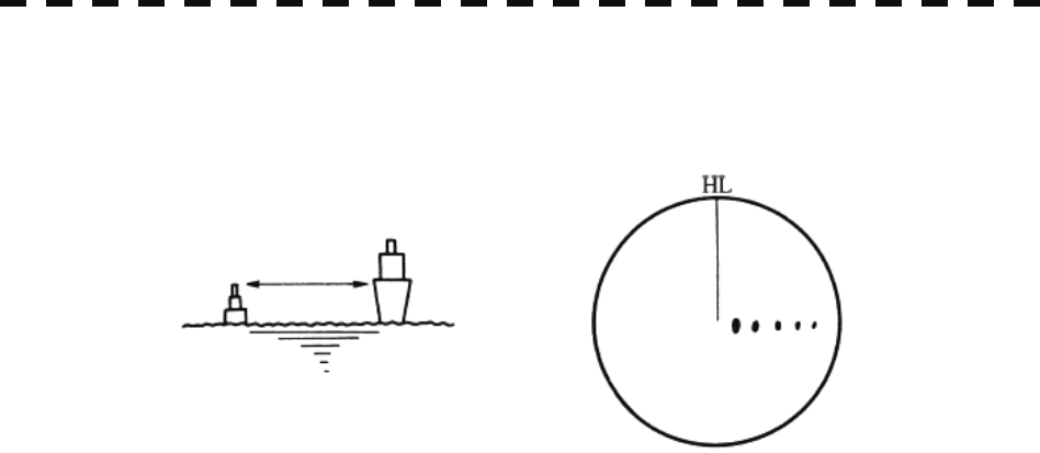
[IV] False Echo by Multiple Reflection
When there is a large structure or ship with a high vertical surface near own ship as shown in Figure 5.,
multiple refection returns may appear on the radar display. These echoes appear in the same intervals, of
which the nearest echo is the true echo of the target.
Figure 5.6
[V] Abnormal Propagation
The maximum radar detection range depends upon the height of the scanner and the height of a target as
described in the section of “The Horizon for Radar Beam Radiation”. If a so-called “duct” occurs on the
sea surface due to a certain weather condition, however, the radar beam may propagate to a abnormally
long distance, at which a target may be detected by the radar.
For instance, assuming that the radar range is 4 km (on the repetition frequency of 4000 Hz), the first pulse
is reflected from a target at about 37.5 km or more and received during the next pulse repetition time. In
this case, a false echo appears at a position that is about 37.5 km shorter than the actual distance.
If the false echo appears at 5 NM on the radar display, the true distance of the target is 2+37.5=39.5 km.
This type of false echo can be discriminated by changing over the range scale (the repetition frequency),
because the distance of the target changes accordingly.
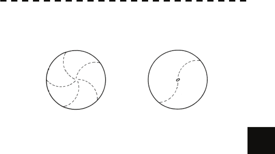
5-8
5.4 FALSE ECHOES yy
yyy
5
[VI] Radar Interference
When another radar equipment using the same frequency band as that on own ship is near own ship, a
radar interference pattern may appear on the radar display. This interference pattern consists of a number
of spots which appear in various forms. In many cases, these spots do not always appear at the same
places, so that they can be discriminated from the target echoes. (See Figure 5.7)
Figure 5.7
If radar equipment causing an interference pattern and this radar are of the same model, their transmitting
repetition frequency is nearly the same. As a result, interference patterns may be displayed
concentrically.
In this case, the interference patterns cannot be eliminated by using only the interference reflector function,
so press [TX/PRF] several times to fine-tune the transmitting repetition frequency.
An interference suppressing effect can be heightened by applying a different transmitting repetition
frequency to the interference pattern source radar and this radar.

5-9
5.5 DISPLAY OF RADAR TRANSPONDER
(SART)
The SART (Search and rescue Radar Transponder) is a survival device authorized by the GMDSS (Global
Maritime Distress and Safety System), which is used for locating survivors in case that a distress accident
occurs at sea. The SART is designed to operate in the 9 GHz frequency band.
When receiving the 9 GHz radar signal (interrogating signal) transmitted from the radar equipment on a rescue
ship or search aircraft, the SART transmit a series of response signals to inform the distress position to the
rescue and search party.
The setting for SART signal reception
(1) Sea clutter control: Minimum (Most counterclockwise)
(2) AUTO SEA function: OFF
(3) Rain and Snow Clutter Control (RAIN): minimum
(4) Auto Rain and Snow Clutter Yesterday (AUTO RAIN): minimum
(5) TUNE control: No tuning (to weaken clutter echoes)
(6) Interference rejector (IR): OFF
Figure 5.8 [Example of Display]
SART code
Position of SART
Position of the rescue craft
Other ships
Land
z When you set the radar to detect the SART signal, small targets around
own ship will disappear from the radar display. So it is necessary to
exercise full surveillance over the conditions around own ship by visual
watch in order to avoid any collision or stranding.
If two or more sets of radar equipment are installed on own ship, use
one set of 9 GHz band radar for detection of the SART signal and
operate others as normal radars for avoiding collision, monitoring
targets around own ship, and checking on own ship’s position and
avoidance of stranding.
After end of detecting the START signal, adjust the radar normally
again. Then the radar returns normally to the nautical mode.
Attention
SECTION 6
MAINTENANCE
6.1 Routine Maintenance .................................... 6-1
6.2 Maintenance on each Unit............................ 6-2
Scanner Unit NKE-316 .................................. 6-2
Display Unit NCD-1486 ................................. 6-7
6-1
6.1 ROUTINE MAINTENANCE
WARNING
Never carry out internal inspection or repair work
of the equipment by users.
Inspection or repair work by unauthorized
personnel may result in fire hazard or electric
shock.
Ask the nearest branch, business office or a dealer
for inspection and repair.
Turn off the main power before maintenance work.
Otherwise, an electric shock may result.
Turn off the main power before cleaning the
equipment. Especially, make sure to turn off the
indicator if a rectifier is used. Otherwise,
equipment failure, or death or serious injury due to
electric shock may result, because voltage is
outputted from the rectifier even when the radar is
not operating.
For operating the radar equipment in the good conditions, it is necessary to make the maintenance work as
described below. If maintenance is made properly, troubles will reduce. It is recommended to make regular
maintenance work.
Common points of maintenance for each unit are as follow:
Clean the equipment.
Remove the dust, dirt, and sea water rest on the equipment cabinet with a piece of dry cloth.
Especially, clean the air vents with a brush for good ventilation.
6-2
6.2 MAINTENANCE OF EACH UNIT
y
yy
yyy
6
6.2 MAINTENANCE ON EACH UNIT
Scanner Unit NKE-316
WARNING
Turn off the main power source before starting
maintenance.
Otherwise, an electric shock or injury may be
caused.
Turn off the main power if you need to be near the
scanner unit for maintenance or inspection
purposes. Direct exposure to electromagnetic
waves at close range in death or serious injury.
Set the safety switch for stopping the scanner unit
to the OFF position.
Otherwise, an accidental contact with the rotating
scanner unit may cause injury.
6-3
CAUTION
Do not put watches, clocks, or magnetic cards
close to the modulator unit since this unit holds
magnetrons having strong magnetic force.
Failure or data destruction of the above devices
may result.
After finishing the maintenance work, reset the safety switch to the ON position.
Precautions in Mounting the Cover
When the cover is removed for regular checkup and replacement of parts and refitted after such work, the
procedures of fastening bolts shall be taken with the following precautions:
(a) The proper fastening torque of the fitting bolts (M8) is 1176 to 1470 N•cm (120 to 150kgf•cm) (which
makes the inside water-tight and protects the packings against permanent compressive strain).
The packings start producing from the cover at a torque of approximately 1470N•cm (150kgf•cm).
Do not fasten the bolts with a torque exceeding the specified value. Otherwise, the screws may be
broken.
(b) Use an offset wrench of 11 mm × 13 mm or a double-ended wrench of 13 mm × 17 mm (not longer than
200 mm).
(c) Screw all the bolts by hand first to prevent them playing, then fasten them evenly in order not to cause
one-sided fastening. (Fasten the bolts with 25% of the required torque at the first step.)
*: Fasten the bolts in the diagonal order.
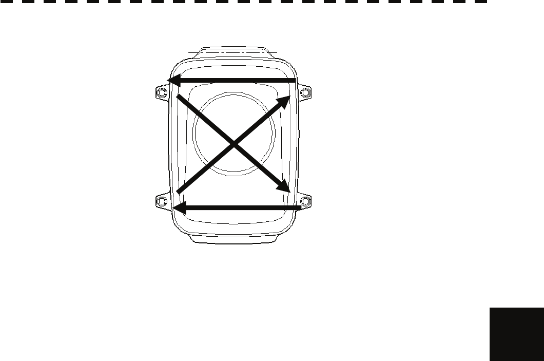
6-4
6.2 MAINTENANCE OF EACH UNIT
y
yy
yyy
6
Top View of NKE-316
Figure 6.1 Bolt Tightening Procedure of NKE-316 Cover
④ ③
② ①

6-5
(1) Radiator
Check up and clean the radiator.
z If the radiator front face (radiation plane) is soiled
with smoke, salt, dust, paint or birds’ droppings,
wipe it with a piece of soft cloth wetted with alcohol
or water and try to keep it clean at all times.
Otherwise, radar beam radiation may attenuate or
reflect on it, resulting in deterioration of radar
performance.
z Never use solvents of gasoline, benzine,
trichloroethylene and ketone for cleaning.
Otherwise, the radiation plane may deteriorate.
Attention

6-6
6.2 MAINTENANCE OF EACH UNIT
y
yy
yyy
6
(2) Rotating section
(a) Supply Oil Seal
When there is not a grease nipple, the replenishment of grease oil is unnecessary.
Remove the cap on the grease nipple located on the side of the X band radar or on the front of S
band radar at which the radiator is supported, and grease with a grease gun.
Make the oiling every six months. The oil quantity shall be approximately 100 g, which is as much
as the grease comes out of the oil seal. Use the grease of Mobilux 2 of Mobil Oil.
(b) Oiling gears
Apply grease evenly to the tooth surfaces of the main shaft drive gear and the encoder drive gear
with a spreader or brush. Oiling in short intervals is more effective to prevent the gears from wear
and tear and extend their service life, but oil at least every six months.
Use Mobilux2 of Mobile Oil.
(c) Mounting legs
Check the mounting legs and mounting bolts of the scanner unit case for corrosion at intervals and
maintain them to prevent danger. Apply paint to them once a half year because painting is the best
measure against corrosion.

6-7
Display Unit NCD-1486
WARNING
When cleaning the screen, do not wipe it too
strongly with a dry cloth. Also, do not use
gasoline or thinner to clean the screen. Otherwise
the screen surface may be damaged.
Dust accumulated on the screen will reduce clarity and darken the video. For cleaning it, wipe it with a piece
of soft cloth (flannel or cotton). Do not wipe it strongly with a piece of dry cloth nor use gasoline or thinner.