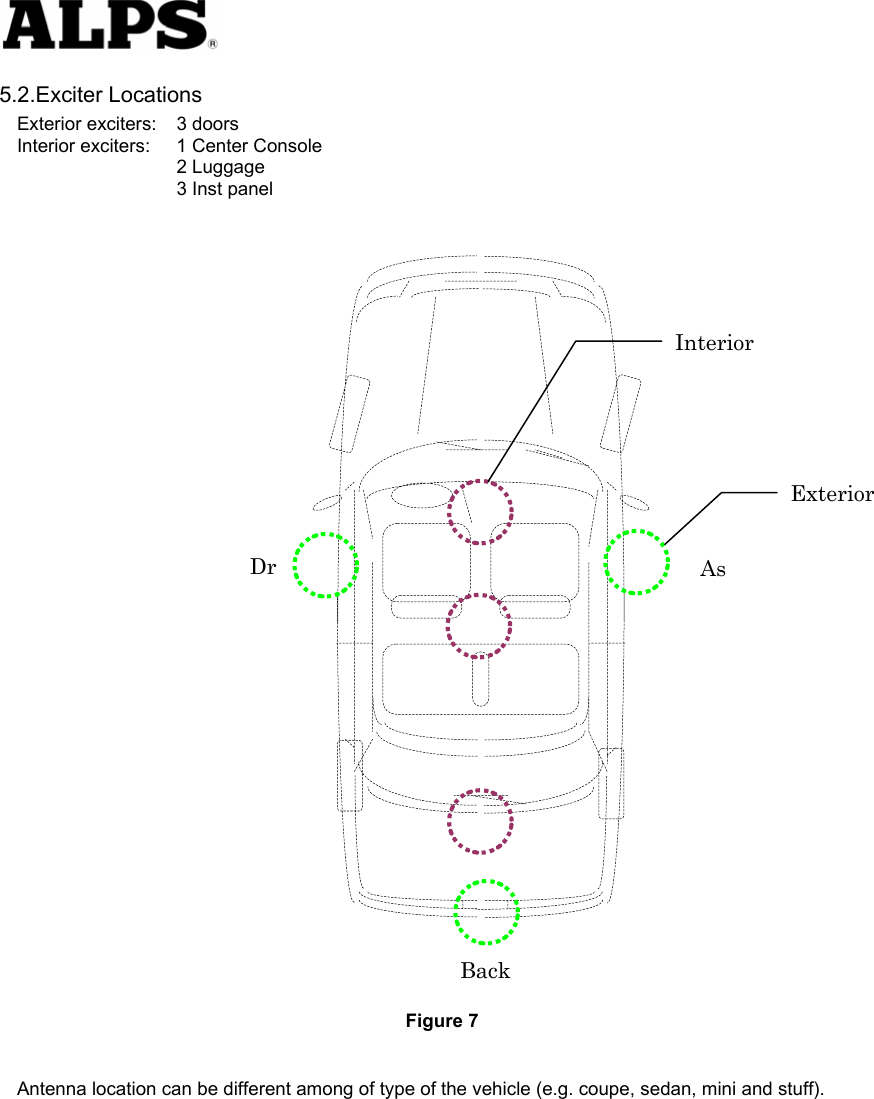
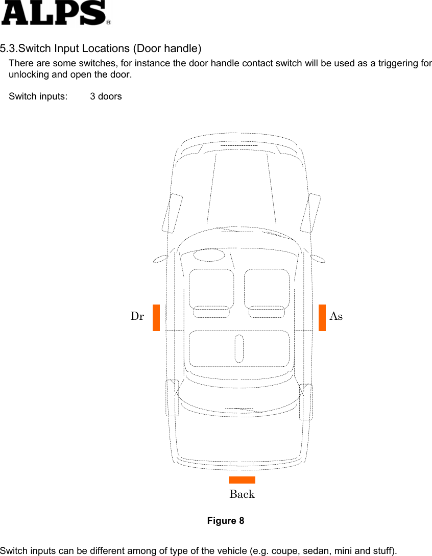
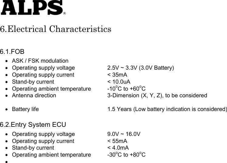
ALPS ALPINE WDU778 Passive Entry System User Manual

Alps Electric Co., Ltd. Passive Entry System

User Manual

  CONTENTS 1.PREFACE .............................................................................................................................................2 2.PASSSIVE ACCSESS ENTRY FUNCTIONALITY...............................................................................3 2.1.Door Unlocking ............................................................................................................................................... 3 2.2.Engine Start.................................................................................................................................................... 4 2.3.Engine Stop .................................................................................................................................................... 4 2.4.Door Locking (Push switch) ............................................................................................................................ 5 3.ACTIVE ACCESS ENTRY FUNCTIONALITY......................................................................................6 3.1.Door Unlocking ............................................................................................................................................... 6 3.2.Engine Start.................................................................................................................................................... 6 3.3.Engine Stop .................................................................................................................................................... 6 3.4.Door Locking .................................................................................................................................................. 6 4.ENTRY SYSTEM OPTIONS .................................................................................................................7 4.1.System Schematic.......................................................................................................................................... 7 4.2.Modules .......................................................................................................................................................... 7 4.2.1.FOB ECU.............................................................................................................................................. 7 4.2.2.Entry System ECU ................................................................................................................................ 7 5.SYSTEM CHARACTERISTICS ............................................................................................................8 5.1.Antenna Areas................................................................................................................................................ 8 5.2.Exciter Locations ............................................................................................................................................ 9 5.3.Switch Input Locations (Door handle)........................................................................................................... 10 6.ELECTRICAL CHARACTERISTICS ..................................................................................................11 6.1.FOB .............................................................................................................................................................. 11 6.2.Entry System ECU........................................................................................................................................ 11 FCC WARNING......................................................................................................................................12 NOTICE ..................................................................................................................................................12
  1.Preface This document describes the requirements and operation of the Passive Entry System.    However, this document is especially for the Entry system ECU (acronym for Electric Control Unit) and the FOB.  The FOB consists the following functionality for passive access and active access:  •  Door unlocking / locking (however, only for request by means of switch operation) •  LF decoding •  RF encoding •  Communication data encryption (cryptograph, anti-collision, rolling code and stuff)  And the entry system ECU consists of the following functionality:    •  Door unlocking / locking •  Engine start (/ stop) •  LF encoding •  RF encoding •  Communication data encryption (cryptograph, anti-collision, rolling code and stuff) •  LF antenna unit control •  Communication with the node ECUs connected to the body bus (e.g. CAN, J1850, customer dependent bus)  As a further function, both the FOB and the entry system ECU provides the following function:  •  Learning mode for programming the manufacturing data and stuff •  Data locking and password protection •  Diagnostic (based upon ISO9141 if required)
  2.Passsive Accsess Entry Functionality A handle sw located on, for example the door handles and mirrors will be used for proximity check if user is in neighborhood of the vehicle.    The switch input will trigger for unlocking and open the doors  Figure 1 2.1.Door Unlocking •  User pushes door handle sw. •  ECU sends LF-challenge via exterior antenna.     •  FOB sends RF-response to the ECU.     •  Door unlocking status is engaged.     •  Doors are opened.       Figure 2  Door Handle SWLF RF  FOB
  2.2.Engine Start •  User operates the engine start knob.     •  ECU sends LF-challenge via interior antenna.     •  FOB sends RF-response to the ECU.     •  Immobilizer ECU receives and authorize the response.     •  Engine controller ECU receives the authorization for engine strat.     •  Start the engine.          Figure 3 2.3.Engine Stop •  User operates the engine stop knob.     •  ECU communicates with the other ECU for engine start request.     •  Engine controller ECU receives the request.     •  Stop the engine   Figure 4    LF RFFOB
  2.4.Door Locking (Push switch) •  User closes the door and pushes the switch (sensing of door locking switch).     •  ECU sends LF-challenge via exterior antenna.     •  FOB sends RF-response to the ECU.     •  Door locking status is engaged.     •  Doors are locked.     •  (Indicates the door locking status by means of Flasher / Buzzer or stuff)   Figure 5
  3.Active Access Entry Functionality  3.1.Door Unlocking Same functionality as the current one.      3.2.Engine Start This function does not effect on the active entry system.      3.3.Engine Stop This function does not have influence on the active entry system.      3.4.Door Locking Same functionality as the current one.
  4.Entry System Options  4.1.System Schematic                 4.2.Modules 4.2.1.FOB ECU                4.2.2.Entry System ECU                     OTHER ECUS LF (>2Kbps) Local Bus ECUECUECUBody Bus ENTRY SYSTEM ECU  FOB 125kHz RF (>4Kbps) 315MHz FOB RF Amp LF Amp ASIC Z X Y Lock   Unlock   Panic Emergency key (Transponder) 125kHz 315MHz ENTRY SYSTEM ECU MCU Dr Door handle As Door handle Back Door handle Push knob (Engine start knob) Body Bus Local Bus LF ExciterLF ExciterLF ExciterLF ExciterRoom1 Dr As Back 125kHz Dr : Driver Door Antenna As : Assist Door Antenna Back : Back Door Antenna Exterior Antenna Room1: Console Antenna   Room2: Luggage Antenna   Room3: Inst. Antenna Interior Antenna LF ExciterLF ExciterRoom2 Room3 Tuner signal
  5.System Characteristics  5.1.Antenna Areas Exterior operating range:  0.8m to 1.5m Interior operating range:  Only inside the car  Number of the exterior exciters :  typ.3, however, it is depending on the type of the vehicle. Number of the interior exciters:  max.4 (min.2)                                       Figure 6  Exterior antenna functionality: •  Unlock / lock doors. •  Activate / deactivate alarm system.     •  Activate immobilizer    Interior antenna functionality: •  Deactivate immobilizer •  Engine start   Exterior Interior Dr As Back
  5.2.Exciter Locations Exterior exciters:  3 doors Interior exciters:  1 Center Console      2 Luggage      3 Inst panel                                      Figure 7  Antenna location can be different among of type of the vehicle (e.g. coupe, sedan, mini and stuff).       Exterior Interior Dr  As Back
  5.3.Switch Input Locations (Door handle) There are some switches, for instance the door handle contact switch will be used as a triggering for unlocking and open the door.    Switch inputs:  3 doors                                      Figure 8 Switch inputs can be different among of type of the vehicle (e.g. coupe, sedan, mini and stuff).     Dr As Back
  6.Electrical Characteristics  6.1.FOB •  ASK / FSK modulation •  Operating supply voltage    2.5V ~ 3.3V (3.0V Battery) •  Operating supply current    < 35mA •  Stand-by current    < 10.0uA •  Operating ambient temperature  -10oC to +60oC •  Antenna direction    3-Dimension (X, Y, Z), to be considered    •  Battery life      1.5 Years (Low battery indication is considered)  6.2.Entry System ECU •  Operating supply voltage    9.0V ~ 16.0V •  Operating supply current    < 55mA •  Stand-by current    < 4.0mA •  Operating ambient temperature  -30oC to +80oC •
  FCC WARNING  Changes or modifications not expressly approved by the party responsible for compliance could void the user’s authority to operate the equipment.  NOTICE  This device complies with Part 15 of the FCC Rules and RSS-Gen of IC Rules.   Operation is subject to the following two conditions: (1)    This device may not cause harmful interference, and (2)    This device must accept any interference received, including interference that may        cause undesired operation.  第十二條 經型式認證合格之低功率射頻電機,非經許可,公司、商號或使用者均不得擅自變更頻 率、加大功率或變更原設計之特性及功能。 第十四條 低功率射頻電機之使用不得影響飛航安全及干擾合法通信;經發現有干擾現象時,應立即 停用,並改善至無干擾時方得繼續使用。 前項合法通信,指依電信法規定作業之無線電通信。 低功率射頻電機須忍受合法通信或工業、科學及醫療用電波輻射性電機設備之干擾。

Navigation menu