AMETEK Magnetrol USA R96 Tank Level Probing Radar Transmitter User Manual Layout 1
Magnetrol Tank Level Probing Radar Transmitter Layout 1
UserManual.wiki
>
AMETEK Magnetrol USA
>
R96 User Manual
Exhibit D Users Manual per 2 1033 b3
Navigation menu
Upload a User Manual
Namespaces
Wiki Guide
HTML
PDF
Info
Views
User Manual
Discussion / Help
Navigation

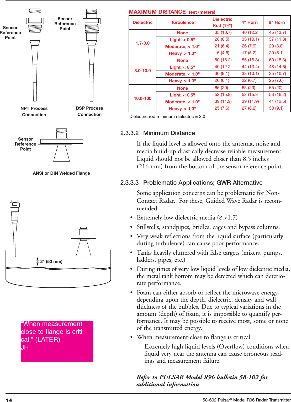
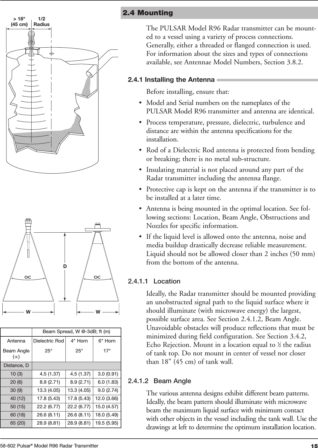
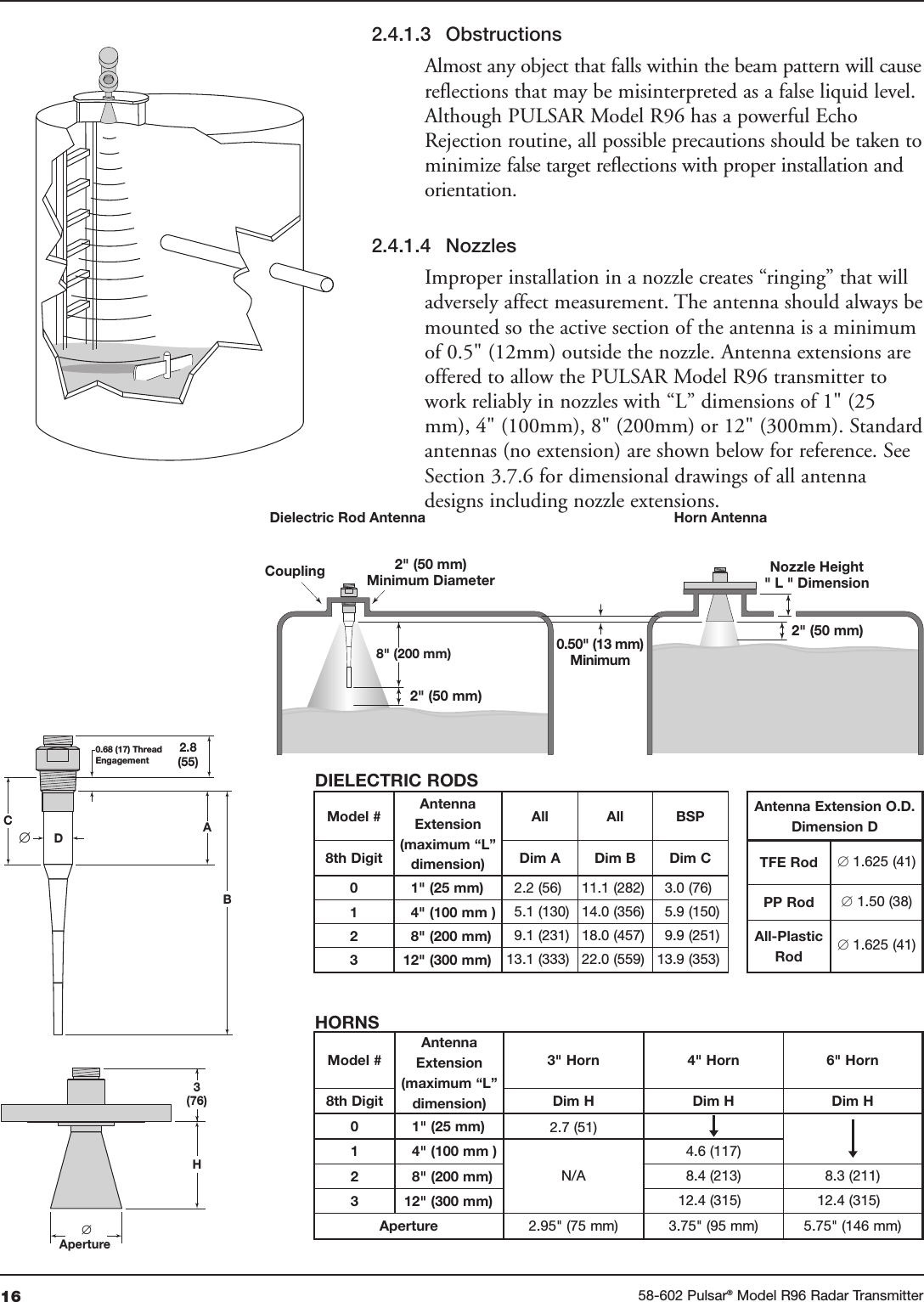
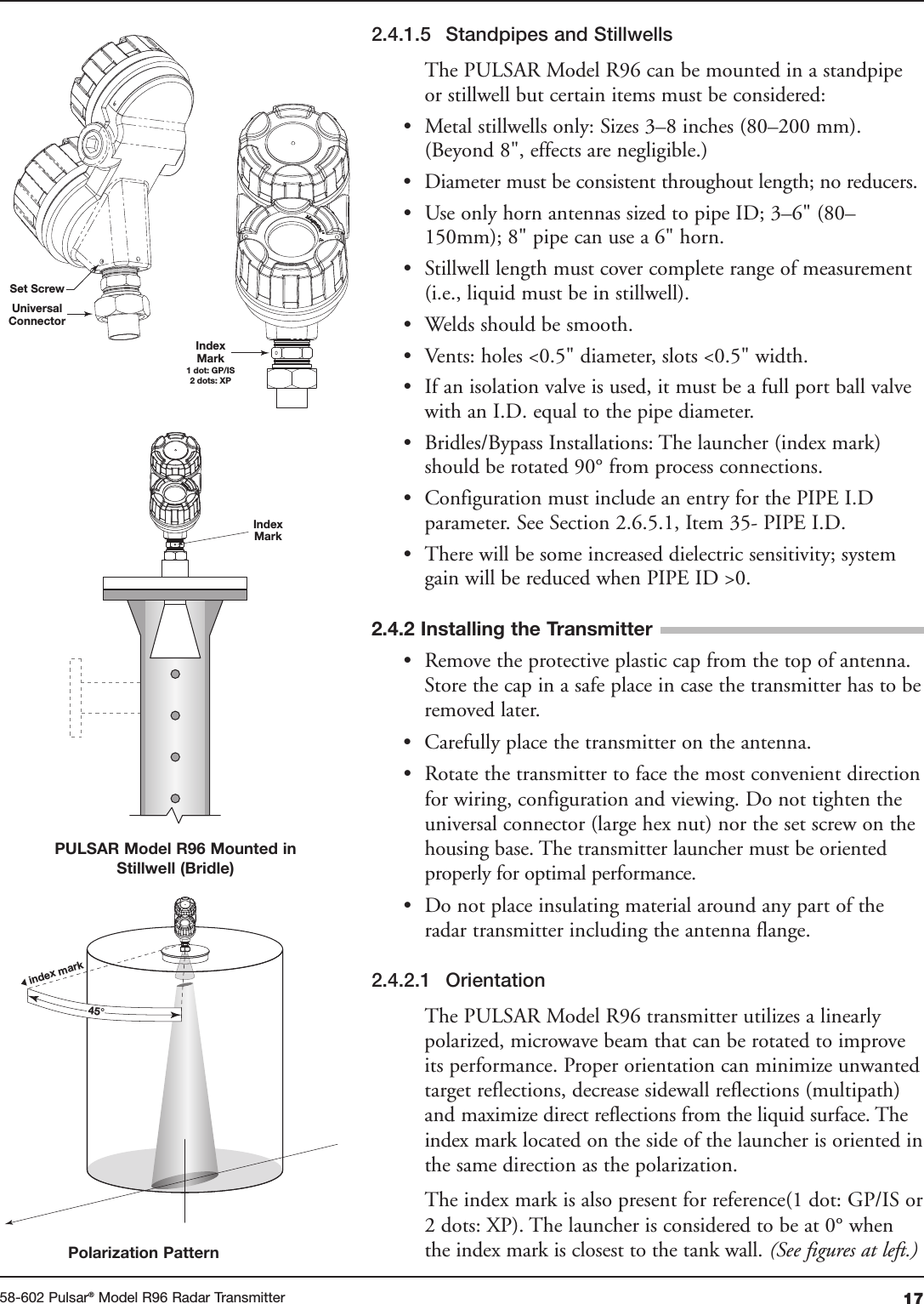
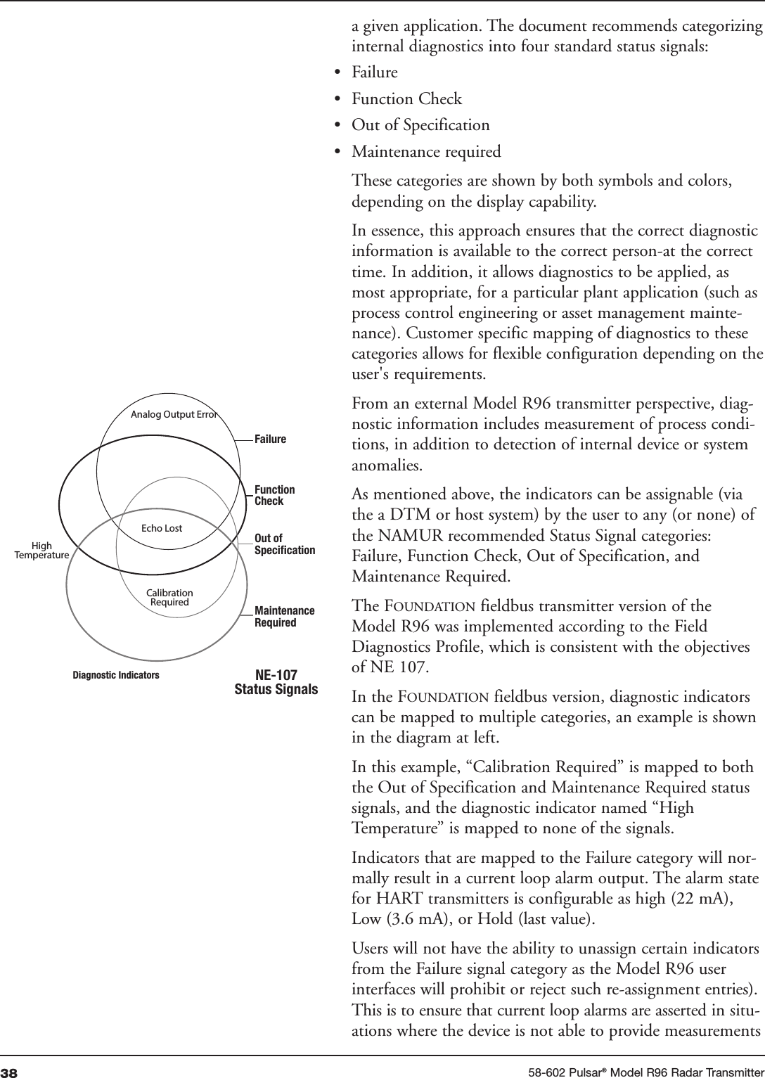
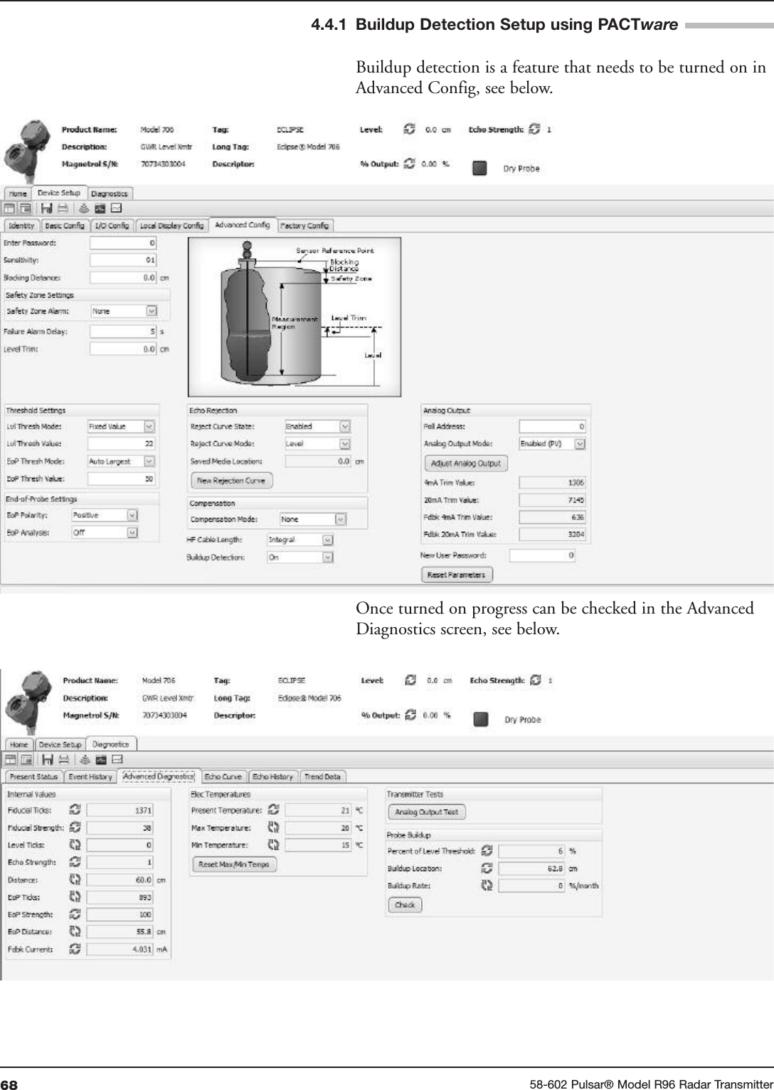
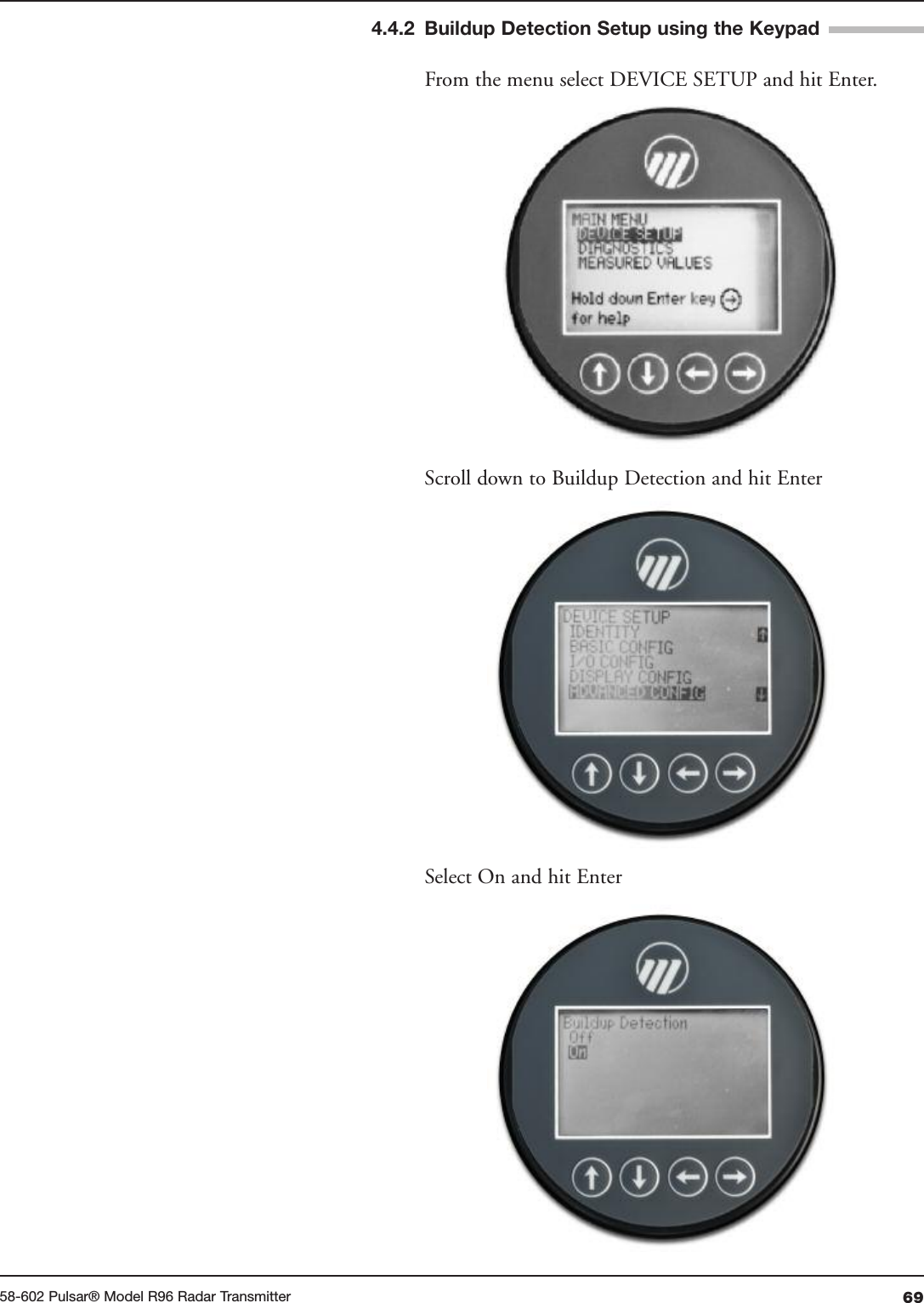
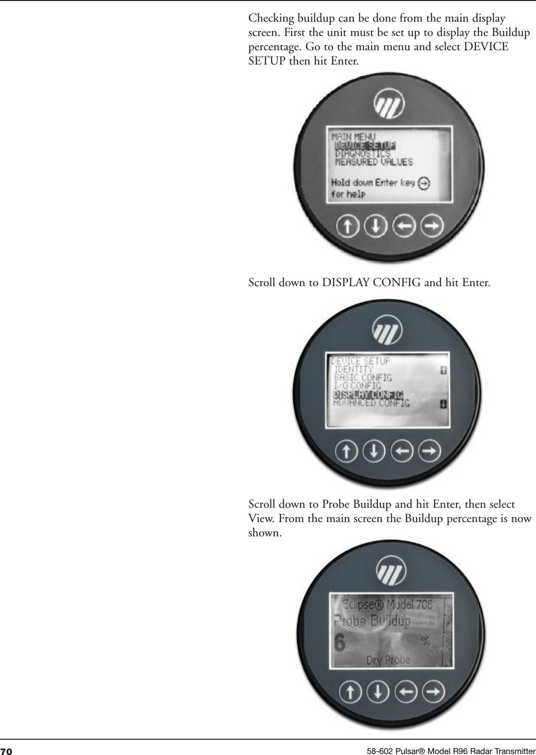
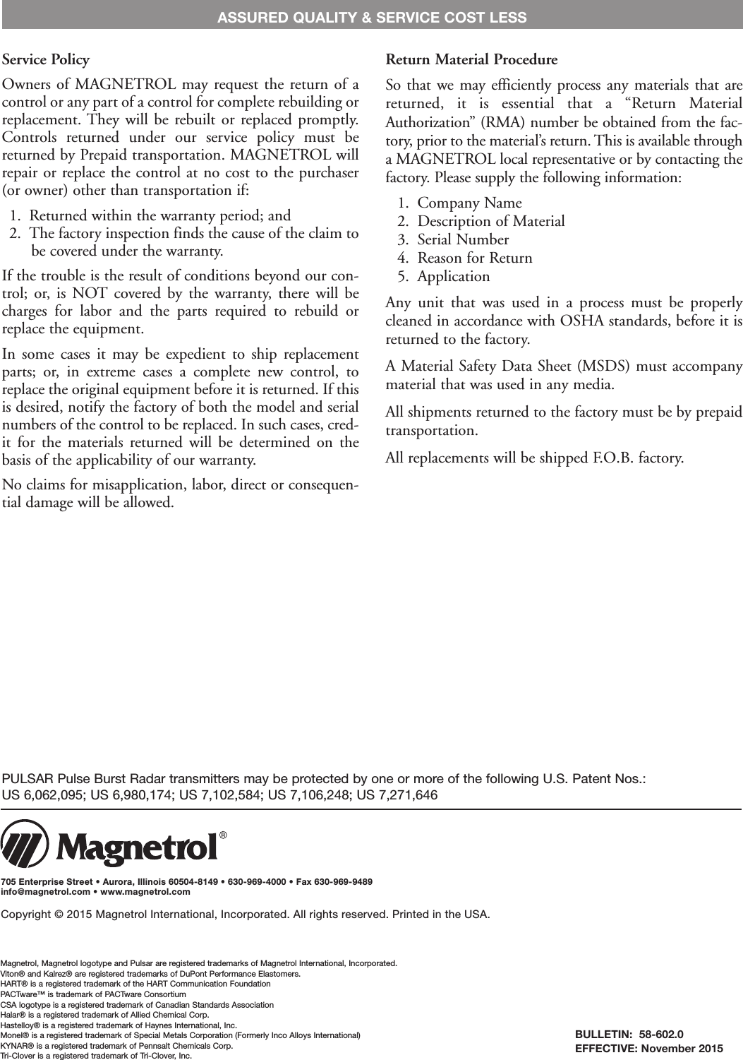
![3158-602 Pulsar®Model R96 Radar TransmitterHome ScreenMain MenuDevice Setup Quick StartIdentityBasic ConfigI/O ConfigDisplay ConfigAdvanced ConfigFactory ConfigSensitivity:0 to 100 echo strength unitsTop Blocking Distance:-7.5 to +100 feet(-2 m to 30 m)Bottom Blocking Distance:-7.5 to +100 feet(-2 m to 30 m)SAFETY ZONE SETTINGSSafety Zone Alarm:None3.6 mA22 mALatched 3.6 mALatched 22 mASafety Zone Height:(not used when Safety Alarm is None)2 inches to 100 feet(5 cm to 30 m)Reset SZ Alarm (used when Safety Alarm is Latch 3.6 mA or Latch 22 mA)ECHO LOSS SETTINGS:Echo Loss Alarm:Hold3.6 mA2.2 mAEcho Loss Delay:? to ? secondsFailure Alarm Delay:0 to 5 secondsLevel Trim:-2.00 to + 2.00 feet(-0.6 m to + 0.6 m)THRESHOLD SETTINGSTarget Selection:First EchoLargest EchoTarget Thresh Mode:AutomaticFixed ValueTarget Thresh Value:Max (44%)High (25%)Med (16%)Low (11%)Base Threshold:0–99 ESUTime Variable Gain:TVG Start ValueTVG End ValueTVG Start Locn# Run AverageMax Surface VelocityMax Distance JumpEmpty State DelayANALOG OUTPUT:HART Poll Address:0 to 63Loop Current Mode:Disabled (Fixed)Enabled (PV)[Fixed Current Value]4 to 20 mAADJUST ANALOG OUTPUT:Adjust 4mAAdjust 20mANew User Password:0 to 59,999CONFIG CHANGED:Indicator Mode:DisabledEnabledReset Config Chngd:Reset?NoYesReset Parameters:NoYes ](https://usermanual.wiki/AMETEK-Magnetrol-USA/R96/User-Guide-2789425-Page-31.png)