AMETEK Magnetrol USA R96 Tank Level Probing Radar Transmitter User Manual Layout 1
Magnetrol Tank Level Probing Radar Transmitter Layout 1
Exhibit D Users Manual per 2 1033 b3

High Performance 6 GHz
Pulse Burst Radar
Level Transmitter
R96 software 1.x
®
Rate of What is the maxi-
mum rate the level
Change will rise or fall?
_____________
FPO
FPO
PRELIMINARY

58-602 Pulsar® Model R96 Radar Transmitter
Read this Manual Before Installing
This manual provides information on the Pulsar®Model
R96 Radar transmitter. It is important that all instruc-
tions are read carefully and followed in sequence. The
QuickStart Installation instructions are a brief guide to the
sequence of steps for experienced technicians to follow
when installing the equipment. Detailed instructions are
included in the Complete Installation section of this manual.
Conventions Used in this Manual
Certain conventions are used in this manual to convey
specific types of information. General technical material,
support data, and safety information are presented in nar-
rative form. The following styles are used for notes, cau-
tions, and warnings.
NOTES
Notes contain information that augments or clarifies
an operating step. Notes do not normally contain
actions. They follow the procedural steps to which
they refer.
Cautions alert the technician to special conditions that
could injure personnel, damage equipment, or reduce
a component’s mechanical integrity. Cautions are also
used to alert the technician to unsafe practices or the
need for special protective equipment or specific mate-
rials. In this manual, a caution box indicates a poten-
tially hazardous situation which, if not avoided, may
result in minor or moderate injury.
WARNINGS
Warnings identify potentially dangerous situations or
serious hazards. In this manual, a warning indicates an
imminently hazardous situation which, if not avoided,
could result in serious injury or death.
Safety Messages
The PULSAR Model R96 system is designed for use in
Category II, Pollution Degree 2 installations. Follow all
standard industry procedures for servicing electrical and
computer equipment when working with or around high
voltage. Always shut off the power supply before touching
any components. Although high voltage is not present in
this system, it may be present in other systems.
Electrical components are sensitive to electrostatic dis-
charge. To prevent equipment damage, observe safety
procedures when working with electrostatic sensitive
components.
This device complies with Part 15 of the FCC rules.
Operation is subject to the following two conditions:
(1) This device may not cause harmful interference, and
(2) This device must accept any interference received,
including interference that may cause undesired operation.
FCC ID: LPN R95
Any unauthorized changes or modifications not expressly
approved by the party responsible for compliance could
void user’s authority to operate this equipment.
WARNING! Explosion hazard. Do not connect or dis-
connect designs rated Explosion-proof or Non-incendive
unless power has been switched off and/or the area is
known to be non-hazardous.
Low Voltage Directive
For use in Installations Category II, Pollution Degree 2.
If equipment is used in a manner not specified by the
manufacturer, protection provided by equipment may be
impaired.
Notice of Copyright and Limitations
Magnetrol®& Magnetrol®logotype and Pulsar®
are registered trademarks of Magnetrol®International,
Incorporated.
Copyright © 2015 Magnetrol®International,
Incorporated. All rights reserved.
MAGNETROL reserves the right to make changes to the
product described in this manual at any time without
notice. MAGNETROL makes no warranty with respect
to the accuracy of the information in this manual.
Warranty
All MAGNETROL electronic level and flow controls are
warranted free of defects in materials or workmanship for
one full year from the date of original factory shipment.
If returned within the warranty period; and, upon facto-
ry inspection of the control, the cause of the claim is
determined to be covered under the warranty; then,
MAGNETROL will repair or replace the control at no cost
to the purchaser (or owner) other than transportation.
MAGNETROL shall not be liable for misapplication,
labor claims, direct or consequential damage or expense
arising from the installation or use of equipment. There
are no other warranties expressed or implied, except spe-
cial written warranties covering some MAGNETROL
products.
Quality Assurance
The quality assurance system in place at MAGNETROL
guarantees the highest level of quality throughout the
company. MAGNETROL is committed to providing
full customer satisfaction both in quality products and
quality service.
The MAGNETROL quality assurance
system is registered to ISO 9001 affirming
its commitment to known international
quality standards providing the strongest
assurance of product/service quality
available.

58-602 Pulsar® Model R96 Radar Transmitter
Table of Contents
1.0 QuickStart Installation
1.1 Getting Started..........................................................5
1.1.1 Equipment and Tools .....................................5
1.1.2 Configuration Information.............................6
1.2 QuickStart Mounting................................................7
1.2.1 Antenna .........................................................7
1.2.2 Transmitter.....................................................7
1.3 QuickStart Wiring ....................................................7
1.4 QuickStart Configuration .........................................8
1.4.1 QuickStart Menu Options ...........................10
1.4.1.1 QuickStart Numerical Data Entry...........11
2.0 Complete Installation
2.1 Unpacking ..............................................................12
2.2 Electronic Discharge (ESD) Handling Procedure....12
2.3 Before You Begin.....................................................13
2.3.1 Site Preparation ............................................13
2.3.2 Equipment and Tools ...................................13
2.3.3 Operational Considerations..........................13
2.3.3.1 Maximum Distance...............................14
2.3.3.2 Minimum Distance...............................14
2.3.3.3 Problematic Applications;
GWR Alternative ..................................14
2.4 Mounting................................................................15
2.4.1 Installing the Antenna ..................................15
2.4.1.1 Location................................................15
2.4.1.2 Beam Angle...........................................15
2.4.1.3 Obstructions .........................................16
2.4.1.4 Nozzles..................................................16
2.4.1.5 Standpipes and Stillwells .......................17
2.4.2 Installing the Transmitter .............................17
2.4.2.1 Orientation ...........................................17
2.4.2.2 Initial Installation..................................18
2.4.2.3 Low Echo Margin .................................18
2.5 Wiring ....................................................................19
2.5.1 General Purpose or Non-Incendive ..............19
2.5.2 Intrinsically Safe...........................................20
2.5.3 Explosion Proof............................................20
2.6 Configuring the Transmitter....................................21
2.6.1 Bench Configuration....................................21
2.6.2 Menu Traversal and Data Entry....................22
2.6.2.1 Navigating the Menu ............................22
2.6.2.2 Data Selection.......................................22
2.6.2.3 Entering Numeric Data Using
Digit Entry ...........................................23
2.6.2.4 Entering Numberic Data Using
Increment/Decrement ...........................23
2.6.2.5 Entering Character Data .......................24
2.6.3 Password Protection .....................................24
2.6.4 Menu: Step-By-Step Procedure.....................25
2.6.5 Configuration Menu: Device Setup..............28
2.7 Configuration Using HART®..................................33
2.7.1 Connections .................................................33
2.7.2 Display Menu...............................................33
2.7.3 HART Revision Table ..................................33
2.7.3.1 Model R96............................................33
2.7.4 HART Menu................................................34
3.0 Reference Information
3.1 Description .............................................................35
3.2 Theory of Operation...............................................35
3.2.1 Pulse Burst Radar .........................................35
3.2.2 Equivalent Time Sampling ...........................36
3.3 Troubleshooting and Diagnostics ............................37
3.3.1 Diagnostics (Namur NE 107) ......................37
3.3.2 Diagnostic Indication Simulation.................39
3.3.3 Diagnostic Indicator Table ...........................40
3.3.4 Diagnostic Help ...........................................42
3.3.5 Troubleshooting System Problems..................43
3.4 Configuration Information .....................................44
3.4.1 Bottom Blocking Distance Description........45
3.4.2 Echo Rejection .............................................45
3.4.3 Volumetric Capability ..................................45
3.4.3.1 Configuration Using Built-in
Vessel Types...........................................45
3.4.3.2 Configuration Using Custom Table ......47
3.4.4 Reset Function...............................................47
3.5 Agency Approvals....................................................48
3.5.1 Agency Drawing & Entity Parameters..........49
3.6 Parts ........................................................................51
3.6.1 Replacement Parts ........................................51
Pulsar®Pulse Burst Radar Level Transmitter

458-602 Pulsar® Model R96 Radar Transmitter
3.7 Specifications ..........................................................52
3.7.1 Functional – Transmitter..............................52
3.7.2 Functional – Environmental.........................53
3.7.2.1 Safe Operating Area..............................53
3.7.2.2 Supply Voltage ......................................54
3.7.3 O-ring (seal) Selection Chart........................54
3.7.4 Functional – Antenna...................................55
3.7.5 PULSAR Model R96 Antenna
Pressure/Temperature Rings .........................55
3.7.6 Physical ........................................................56
3.8 Model Numbers......................................................57
3.8.1 PULSAR Model R96 Radar Transmitter ......57
3.8.2 Radar Antennas – Dielectric Rod .................58
3.8.3 Radar Antennas – Horn ...............................59
4.0 Advanced Configuration/Troubleshooting Techniques
4.1 End-of-Probe Analysis (EOPA) ................................60
4.1.1 Enable EOPA using PACTware .....................60
4.1.2 Enable EOPA using keyboard/LCD...............61
4.2 Sloped Threshold .....................................................99
4.3 Echo Rejection.........................................................62
4.4 Buildup Detection....................................................64
4.4.1 Buildup Detection Setup
using PACTware ..........................................68
4.4.2 Buildup Detection Setup
using the Keypad..........................................69

5
58-602 Pulsar®Model R96 Radar Transmitter
1.0 QuickStart Installation
The QuickStart Installation procedures provide an overview
of the key steps for mounting, wiring, and configuring the
PULSAR Model R96 radar level transmitter. These proce-
dures are intended for experienced installers of electronic
level measurement instruments.
See Complete Installation, Section 2.0, for detailed installa-
tion instructions.
1.1 Getting Started
Before beginning the QuickStart Installation procedures,
have the right equipment, tools, and information available.
No special tools are needed. The following items are
recommended:
• Threaded antenna and transmitter . . . . . . 2" (50 mm)
• Transmitter/antenna connection. . . . . . . . 13⁄4" (44 mm)
• Transmitter adjustment . . . . . . . . . . . . . . 11⁄8" (28 mm),
3⁄32" (2.5 mm) Hex
• Torque wrench . . . . . . . . . . . . . . . . . . . . . highly desirable
• Flat-blade screwdriver
• Digital multimeter or volt/ammeter . . . . . Optional
• 24 VDC (23 mA) power supply. . . . . . . . Optional

658-602 Pulsar®Model R96 Radar Transmitter
To utilize the QuickStart menu available on the
PULSAR Model R96, some key information is required
for configuration.
Gather the information and complete the following operating
parameters table before beginning configuration.
NOTES: The QuickStart menu is available for Level Only applications.
1. Refer to Section 2.6.5 for configuration menus for Volume
applications.
2. These configuration steps are not necessary if the transmitter
was pre-configured prior to shipment.
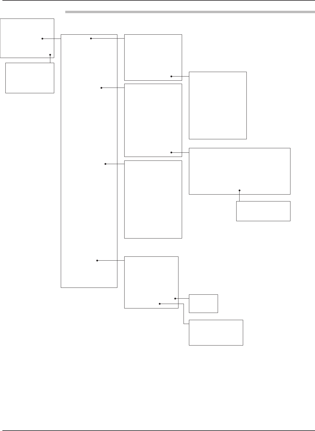
Level What units of measurement will be
Units used? _____________
Tank What is the tank height? _____________
Height
Antenna What type of antenna is being used?
Model Select first 7 digits of Model number.
(See nameplate on side of antenna) _____________
Antenna What is maximum nozzle length that
Extension the antenna can be used?
Select last 3 digits of Model number.
(See nameplate on side of antenna) _____________
Antenna Is the antenna mounting NPT, BSP,
Mount or flanged? _____________
Dielectric What is the dielectric of the process
medium? _____________
Tank Top Is the Tank Top Flat, Horizontal Cylinder,
Dome, Irregular or other (non-metallic)? _____________
Top What is the distance from Sensor
Blocking Reference point to Maximum Level?
Maximum level should never be less
than 2” (50 mm) from bottom of antenna. _____________
Bottom Is there a region at the very bottom of the
Blocking vessel that cannot be measured due to
Distance heating coils, angle tank bottom, etc.? _____________
Turbulence Is turbulence a consideration? _____________
Rate of What is the maximum rate the level
Change will rise or fall? _____________
Foam Will there be foam on the surface? _____________
4 mA What is the 0% reference point for the
Setpoint 4.0 mA value? _____________
(LRV)
20 mA What is the 100% reference point for
Setpoint the 20.0 mA value? _____________
(URV)
Failure What output current is desired when a
Alarm failure indicator is present? _____________
7
58-602 Pulsar®Model R96 Radar Transmitter
1.2 QuickStart Mounting
NOTE: Confirm the configuration style and process connection (size
and type) of the PULSAR Model R96 radar transmitter. Ensure it
matches the requirements of the installation before continuing
with the QuickStart installation.
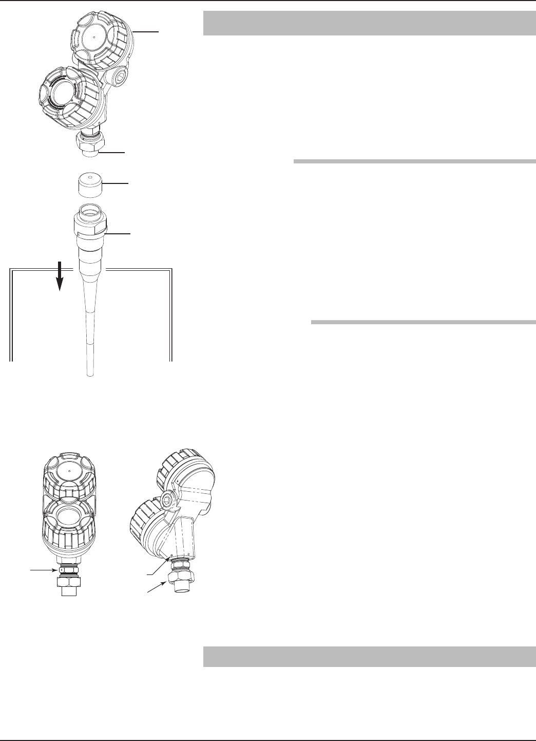
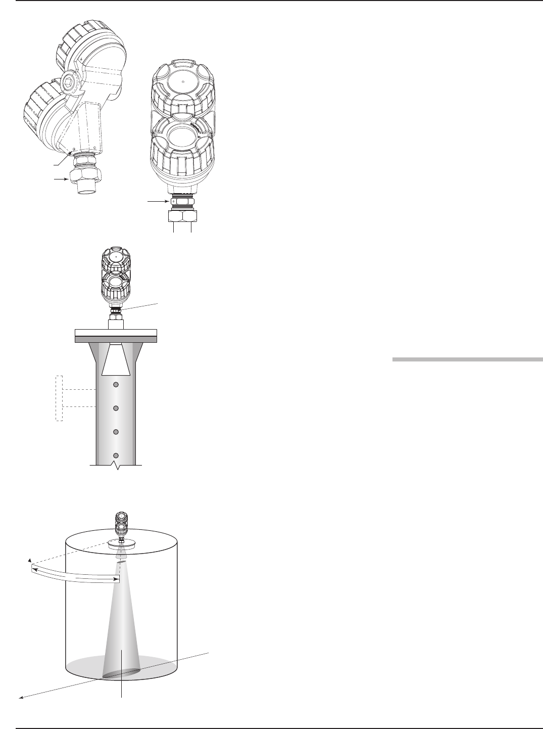
➀Confirm the model and serial numbers on the nameplates
of PULSAR Model R96 electronics and antenna are identi-
cal.
➁Carefully place the antenna into the vessel. Mount in a
location equal to 1⁄2the radius of tank top. Do not mount in
center of vessel nor closer than 18" (45 cm) of tank wall.
➂Secure the antenna to the vessel.
➃Leave the protective plastic cap in place until ready to
install the transmitter.
NOTE: Do not use sealing compound or TFE tape on antenna connec-
tion to transmitter. This connection is sealed by a Viton®O-ring.
1. Remove the protective plastic cap from the top of the
antenna and store for future use. Make sure the bottom of
the Universal connector (Teflon®) ➄and inside of the
antenna are clean and dry. Clean with isopropyl alcohol and
cotton swabs if necessary.
2. Place the transmitter on the antenna.
3. Ensure the housing/launcher set screw is loose and the
housing can be turned. Align the antenna index mark so it
is at an angle of 45° to a line from the radar unit to the
nearest tank wall.
4. Rotate the transmitter so that it is in the most convenient
position for wiring, configuring, and viewing.
5. While keeping the housing and launcher aligned, tighten
both the housing/launcher set screw and large Universal
connector Hex nut. Tighten the universal connector to
30 ft./lbs of force. A torque wrench is highly desirable.
DO NOT LEAVE HAND TIGHT.
• Do not place insulating material around any part of the
Radar transmitter including the antenna flange.
1.3 QuickStart Wiring
WARNING! Explosion hazard. Do not remove covers unless power
has been switched off or the area is known to be non-
hazardous.
➁
➀
➂
➃
➀
➄
Set Screw
Universal
Connector
Index
Mark
1 dot: GP/IS
2 dots: XP
858-602 Pulsar®Model R96 Radar Transmitter
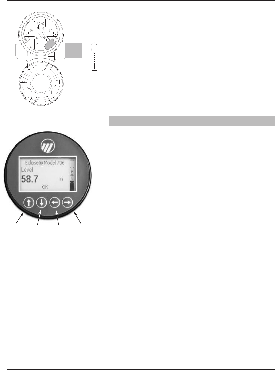
NOTE: Ensure that the electrical wiring to the PULSAR Model R96
radar transmitter is complete and in compliance with all regula-
tions and codes.
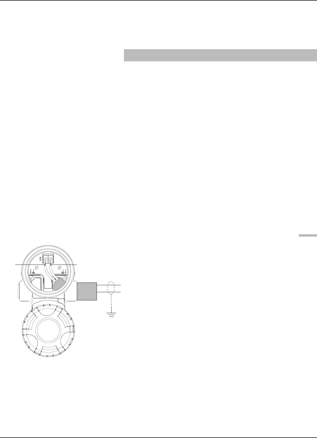
1. Remove the cover of the upper wiring compartment.
2. Attach a conduit fitting and mount the conduit plug in the
spare opening. Pull the power supply wire through the con-
duit fitting.
3. If present, connect cable shield to an earth ground at the
power supply.
4. Connect the positive supply wire to the (+) terminal and the
negative supply wire to the (-) terminal. For Explosion
Proof Installations, see Wiring, Section 2.5.3.
5. Replace the cover and tighten.
1.4 QuickStart Configuration
If requested, the PULSAR Model R96 transmitter is
shipped fully pre-configured for the application and can be
installed immediately. Otherwise it is shipped configured
with default values from the factory and can be easily
reconfigured in the shop. The minimum configuration
instructions follow. Use the information from the operating
parameters table before beginning configuration. See
Configuration Information, Section 1.1.2.
The Quick Start menu offers a very simple two screen
overview showing the basic parameters required for a typical
“Level Only” application.
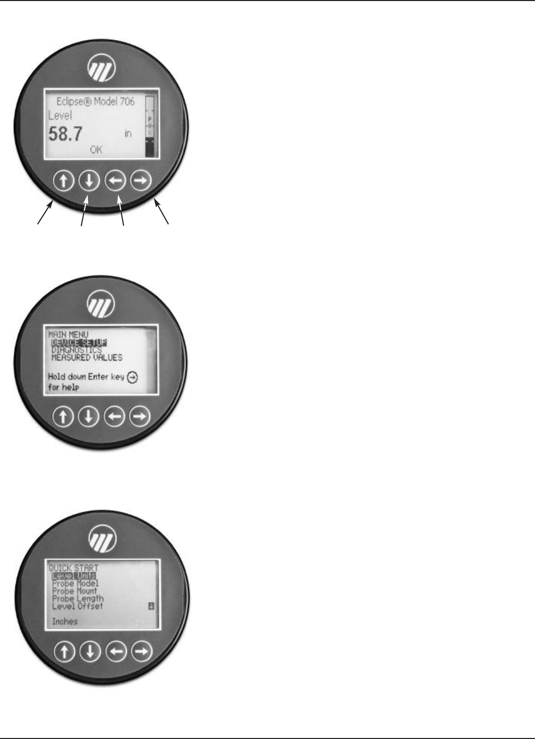
1. Apply power to the transmitter.
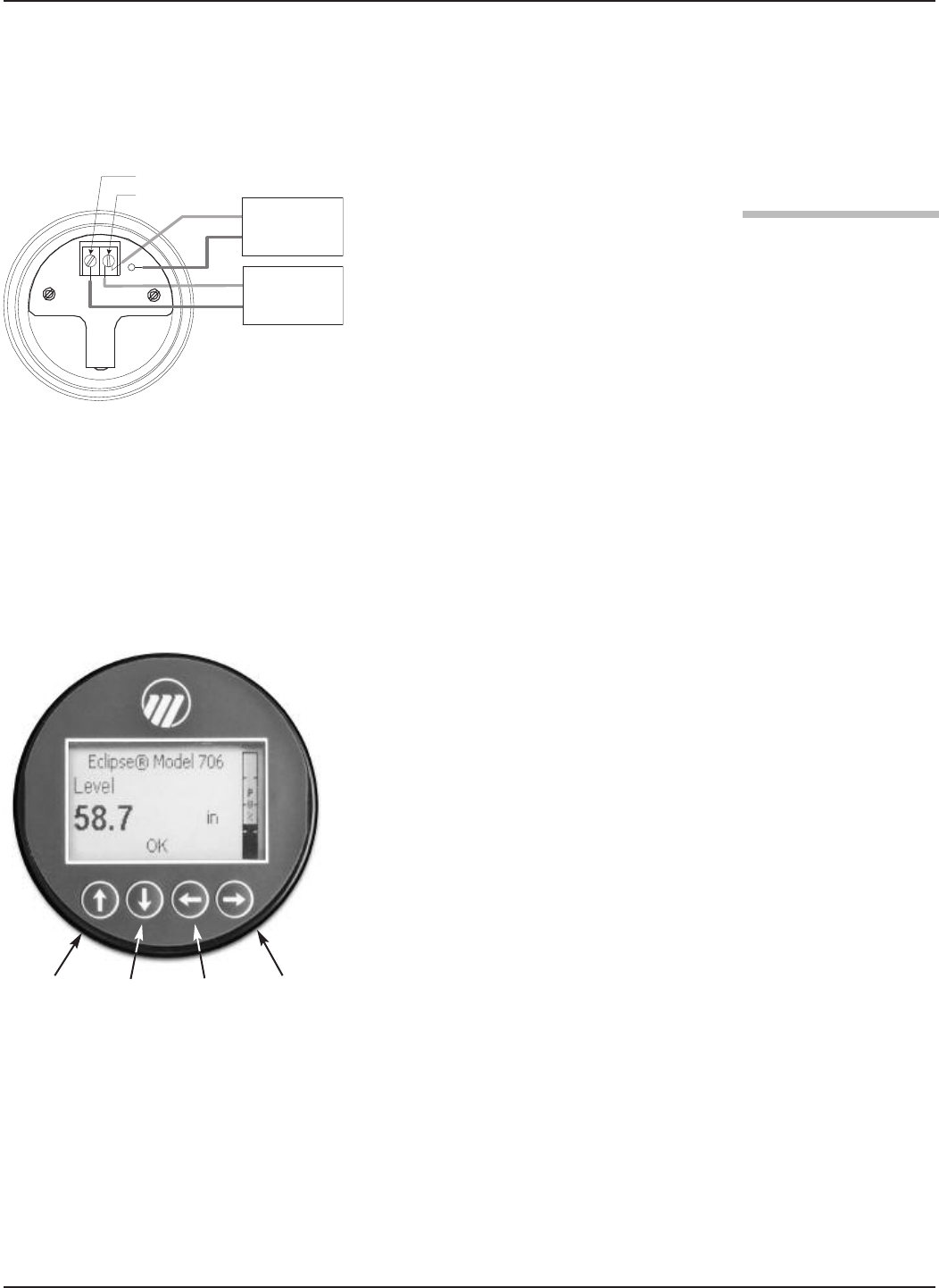
The graphic LCD display can be programmed to change
every 2 seconds to show pertinent Measured Values on the
Home Screen. For example: Level, %Output, and Loop
current can all be displayed on a rotating screen.
The LCD can also be programmed to always show just one
of the Measured Variables at all times. For example: Level
can be the only value displayed on the screen.
2. Remove the cover of the electronic compartment.
Red (+)
Black (-)
(+)
(-)
Up Down Back Enter
FPO
9
58-602 Pulsar®Model R96 Radar Transmitter
3. The push buttons offer multiple forms of functionality for
menu navigation and data entry. (See Section 2.6 for com-
plete explanation).
UP moves up through the menu or increases a displayed
value.
DOWN moves down through the menu or decreases a
displayed value.
BACK exits a branch of the menu or exits without
accepting entered value.
ENTER enters a branch of the menu or accepts a
displayed entry.
NOTE: Holding down ENTER when any menu or parameter is high-
lighted will show help text in reference to that item.
The default User Password = 0. (If a password is requested,
enter it at that time.)
The following configuration entries are the minimum
required for a QuickStart configuration. Refer to figures at
left.
4. Press any key at the Home Screen to access the Main Menu.
5. Press ENTER with the DEVICE SETUP menu item
highlighted.
6. Press ENTER with the QUICKSTART menu item
highlighted.
The QuickStart shows the basic parameters, with the
present value of the highlighted parameter shown at the
bottom of the screen.
One can now quickly and easily scroll through the
QuickStart configuration items, changing those parameters
as required:
• Scroll to the parameter to be changed.
• Press ENTER at the highlighted parameter.
• Scroll to the desired option, then press ENTER.
• Scroll to next parameter or press BACK when
finished to exit the QuickStart menu.
Section 1.4.1 lists and describes the nine parameters in the
QuickStart menu.
7. After making all of the necessary changes in the QuickStart
menu, press the BACK button three times to return to the
Home Screen.
8. The QuickStart configuration is complete. If properly con-
figured, the Model R96 transmitter is measuring level and is
ready for service.
➪
➪
➪
➪
➪
➪
➪
➪
➪
Up Down Back Enter
FPO
FPO
FPO

10 58-602 Pulsar®Model R96 Radar Transmitter
Select the Units of measurement for the level readout:
• Inches • Feet • Millimeters • Centimeters • Meters
Enter tank height (in Level Units selected)
Select the Antenna Model to be used with Model R96:
• RAA-x — TFE rod
• RAB-G — Polypropylene rod
• RAB-L — Polypropylene rod
• RAB-x — Halar rod
• RA3-x — 3” horn
• RA4-x — 4” horn
• RA6-x — 6” horn
0 For nozzel height ≤1" (25 mm) (for threaded process connection only)
1 For nozzel height ≤4" (100 mm)
2 For nozzel height ≤8" (200 mm) (ESP designation for TFE rod only)
3 For nozzel height ≤12" (300 mm)
Select the type of Antenna Mounting to the vessel:
• NPT (National Pipe Thread)
• BSP (British Standard Pipe)
• Flange (ANSI or DIN)
Enter the Dielectric Range for the material to be measured.
Below 1.7 (Light Hydrocarbons like Propane and Butane)
1.7 to 3.0 (Most typical hydrocarbons)
3.0 to 10 (Varying dielectric, for example: mixing tanks)
Above 10 (Water-based media)
Enter the level value (0%-point) for the 4 mA point. Lower Range Value (LRV).
Refer to Section 1.4.1.1.
Enter the level value (100%-point) for the 20 mA point. Upper Range Value (URV).
Refer to Section 1.4.1.1.
Enter the desired output state when a Failure Indicator is active.
• 22 mA
• 3.6 mA
• Hold (Hold last value is not recommended)

11
58-602 Pulsar®Model R96 Radar Transmitter
1.4.1.1 QuickStart Numerical Data Entry
To make numerical entry changes to Tank Height:
UP moves up to the next highest digit (0,1,2,3,....,9 or
the decimal point).
If held down the digits scroll until the push button is
released.
DOWN moves up to the next lowest digit (0,1,2,3,....,9
or the decimal point). If held down the digits scroll until
the push button is released.
BACK moves the cursor to the left and deletes a digit.
If the cursor is already at the leftmost position, then the
screen is exited without changing the previously saved
value.
ENTER Moves the cursor to the right. If the cursor is
located at a blank character position, the new value is
saved.
Scrolling further DOWN in the QuickStart menu results in
the remaining parameters appearing one by one, with the
present highlighted value shown at the bottom of the
screen.
BACK returns to the previous menu without changing
the original value, which is immediately redisplayed.
ENTER accepts the displayed value and returns to the
previous menu.
➪
➪
➪
➪
➪
➪

12 58-602 Pulsar®Model R96 Radar Transmitter
2.0 Complete Installation
This section provides detailed procedures for properly
installing, wiring, configuring, and, as needed, troubleshoot-
ing the PULSAR Model R96 Radar Level Transmitter.
2.1 Unpacking
Unpack the instrument carefully. Make sure all components
have been removed from the packing material. Check all the
contents against the packing slip and report any discrepancies
to the factory.
Before proceeding with the installation, do the following:
• Inspect all components for damage. Report any damage to
the carrier within 24 hours.
• Make sure the nameplate model number on the antenna and
transmitter agree with the packing slip and purchase order.
• Record the model and serial numbers for future reference
when ordering parts.
Model Number
Serial Number
2.2 Electrostatic Discharge (ESD)
Handling Procedure
MAGNETROL electronic instruments are manufactured to
the highest quality standards. These instruments use electronic
components that may be damaged by static electricity present
in most work environments.
The following steps are recommended to reduce the risk of
component failure due to electrostatic discharge.
• Ship and store circuit boards in anti-static bags. If an anti-
static bag is not available, wrap the board in aluminum foil.
Do not place boards on foam packing materials.
• Use a grounding wrist strap when installing and removing
circuit boards. A grounded workstation is recommended.
• Handle circuit boards only by the edges. Do not touch
components or connector pins.
• Make sure that all electrical connections are completely
made and none are partial or floating. Ground all equip-
ment to a good, earth ground
WARNING! Potential electrostatic charging hazard. Do not rub
with dry cloth.

13
58-602 Pulsar®Model R96 Radar Transmitter
2.3 Before You Begin
Each PULSAR Model R96 Radar transmitter/antenna is
built to match the physical specifications of the required
installation. Ensure that the probe process connection is
correct for the threaded or flanged mounting on the vessel
where the transmitter will be placed. See Mounting, Section
2.4.
Ensure that all local, state, and federal regulations and
guidelines are observed. See Wiring, Section 2.5.
Ensure that the wiring between the power supply and
PULSAR Model R96 Radar transmitter is complete and
correct for the type of installation. See Specifications,
Section 3.7.
No special tools are needed. The following items are
recommended:
• Threaded antenna and transmitter . . . . . . 2" (50 mm)
• Transmitter/antenna connection. . . . . . . . 13⁄4" (44 mm)
• Transmitter adjustment . . . . . . . . . . . . . . 11⁄8" (28 mm),
. . . . . . . . . . . . . . . . . . . . . . . . . . . . . . . . . . . . . . . . . . . . . . . . . . . . . . . 3⁄32" (2.5 mm) Hex
• Torque wrench . . . . . . . . . . . . . . . . . . . . . highly desirable
• Flat-blade screwdriver. . . . . . . . . . . . . . . . highly desirable
• Digital multimeter or volt/ammeter . . . . . Optional
• 24 VDC (23 mA) power supply. . . . . . . . Optional
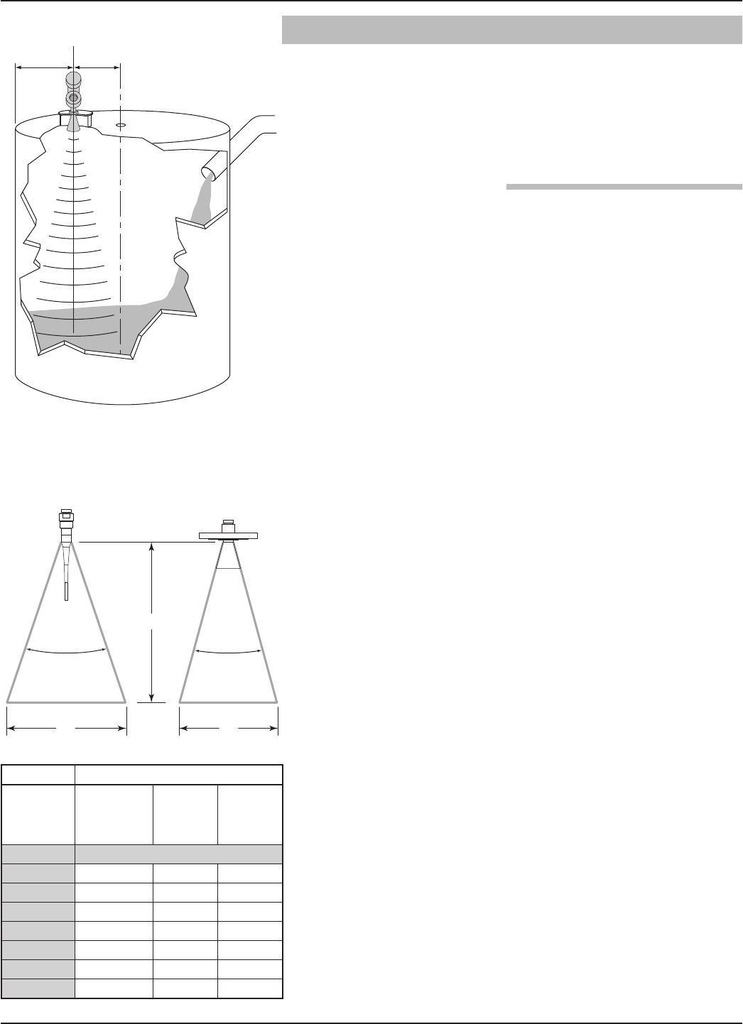
Radar applications are characterized by three basic conditions;
Dielectric (process medium), Distance (measuring range)
and Disturbances (turbulence, foam, false targets, multiple
reflections and rate of change). The PULSAR Model R96
Radar transmitter is offered with two antenna configura-
tions—Horn (3", 4" 6") and Dielectric Rod. Ideally, the 6"
(DN150) Horn antenna should be used to ensure the best
possible performance in all operational conditions.
2.3.3.1 Maximum Distance
The chart on the following page shows the maximum meas-
uring range (Distance) of each antenna based on fundamen-
tal conditions of Dielectric, Distance and Turbulence.
Distance is measured from the Sensor Reference Point (bot-
tom of NPT thread, top of BSP thread or face of a flange).
14 58-602 Pulsar®Model R96 Radar Transmitter
2.3.3.2 Minimum Distance
If the liquid level is allowed onto the antenna, noise and
media build-up drastically decrease reliable measurement.
Liquid should not be allowed closer than 8.5 inches
(216 mm) from the bottom of the sensor reference point.
2.3.3.3 Problematic Applications; GWR Alternative
Some application concerns can be problematic for Non-
Contact Radar. For these, Guided Wave Radar is recom-
mended:
• Extremely low dielectric media (εr<1.7)
• Stillwells, standpipes, bridles, cages and bypass columns.
• Very weak reflections from the liquid surface (particularly
during turbulence) can cause poor performance.
• Tanks heavily cluttered with false targets (mixers, pumps,
ladders, pipes, etc.)
• During times of very low liquid levels of low dielectric media,
the metal tank bottom may be detected which can deterio-
rate performance.
• Foam can either absorb or reflect the microwave energy
depending upon the depth, dielectric, density and wall
thickness of the bubbles. Due to typical variations in the
amount (depth) of foam, it is impossible to quantify per-
formance. It may be possible to receive most, some or none
of the transmitted energy.
• When measurement close to flange is critical
Extremely high liquid levels (Overflow) conditions when
liquid very near the antenna can cause erroneous read-
ings and measurement failure.
Refer to PULSAR Model R96 bulletin 58-102 for
additional information
35 (10.7) 40 (12.2 45 (13.7)
28 (8.5) 33 (10.1) 37 (11.3)
21 (6.4) 26 (7.9) 29 (8.8)
15 (4.6) 17 (5.2) 20 (6.1)
50 (15.2) 55 (16.8) 60 (18.3)
40 (12.2 44 (13.4) 48 (14.6)
30 (9.1) 33 (10.1) 35 (10.7)
20 (6.1) 22 (6.7) 25 (7.6)
65 (20) 65 (20) 65 (20)
52 (15.8) 52 (15.8 53 (16.2)
39 (11.9) 39 (11.9) 41 (12.5)
25 (7.6) 27 (8.2) 30 (9.1)
2" (50 mm)
Sensor
Reference
Point
Sensor
Reference
Point
Sensor
Reference
Point
Dielectric rod minimum dielectric = 2.0
“When measurement
close to flange is criti-
cal.” (LATER)
JH
15
58-602 Pulsar®Model R96 Radar Transmitter
2.4 Mounting
The PULSAR Model R96 Radar transmitter can be mount-
ed to a vessel using a variety of process connections.
Generally, either a threaded or flanged connection is used.
For information about the sizes and types of connections
available, see Antennae Model Numbers, Section 3.8.2.
Before installing, ensure that:
•Model and Serial numbers on the nameplates of the
PULSAR Model R96transmitter and antenna are identical.
•Process temperature, pressure, dielectric, turbulence and
distance are within the antenna specifications for the
installation.
•Rod of a Dielectric Rod antenna is protected from bending
or breaking; there is no metal sub-structure.
•Insulating material is not placed around any part of the
Radar transmitter including the antenna flange.
•Protective cap is kept on the antenna if the transmitter is to
be installed at a later time.
•Antenna is being mounted in the optimal location.See fol-
lowing sections: Location, Beam Angle, Obstructions and
Nozzles for specific information.
•If the liquid level is allowed onto the antenna, noise and
media buildup drastically decrease reliable measurement.
Liquid should not be allowed closer than 2 inches(50 mm)
from the bottom of the antenna.
2.4.1.1Location
Ideally, the Radar transmitter should be mounted providing
an unobstructed signal path to the liquid surface where it
should illuminate (with microwave energy) the largest,
possible surface area. See Section 2.4.1.2, Beam Angle.
Unavoidable obstacles will produce reflections that must be
minimized during field configuration. See Section 3.4.2,
Echo Rejection. Mount in a location equal to 1⁄2the radius
of tank top. Do not mount in center of vessel nor closer
than 18" (45 cm) of tank wall.
2.4.1.2Beam Angle
The various antenna designs exhibit different beam patterns.
Ideally, the beam pattern should illuminate with microwave
beam the maximum liquid surface with minimum contact
with other objects in the vessel including the tank wall. Use the
drawings at left to determine the optimum installation location.
1/2
Radius
> 18"
(45 cm)
D
WW
∝ ∝
Beam Spread, W @-3dB; ft (m)
Antenna
Beam Angle
(∝)
Dielectric Rod
25°
4" Horn
25°
6" Horn
17°
Distance, D
10 (3) 4.5 (1.37) 4.5 (1.37) 3.0 (0.91)
20 (6) 8.9 (2.71) 8.9 (2.71) 6.0 (1.83)
30 (9) 13.3 (4.05) 13.3 (4.05) 9.0 (2.74)
40 (12) 17.8 (5.43) 17.8 (5.43) 12.0 (3.66)
50 (15) 22.2 (6.77) 22.2 (6.77) 15.0 (4.57)
60 (18) 26.6 (8.11) 26.6 (8.11) 18.0 (5.49)
65 (20) 28.9 (8.81) 28.9 (8.81) 19.5 (5.95)
16 58-602 Pulsar®Model R96 Radar Transmitter
2.4.1.3 Obstructions
Almost any object that falls within the beam pattern will cause
reflections that may be misinterpreted as a false liquid level.
Although PULSAR Model R96 has a powerful Echo
Rejection routine, all possible precautions should be taken to
minimize false target reflections with proper installation and
orientation.
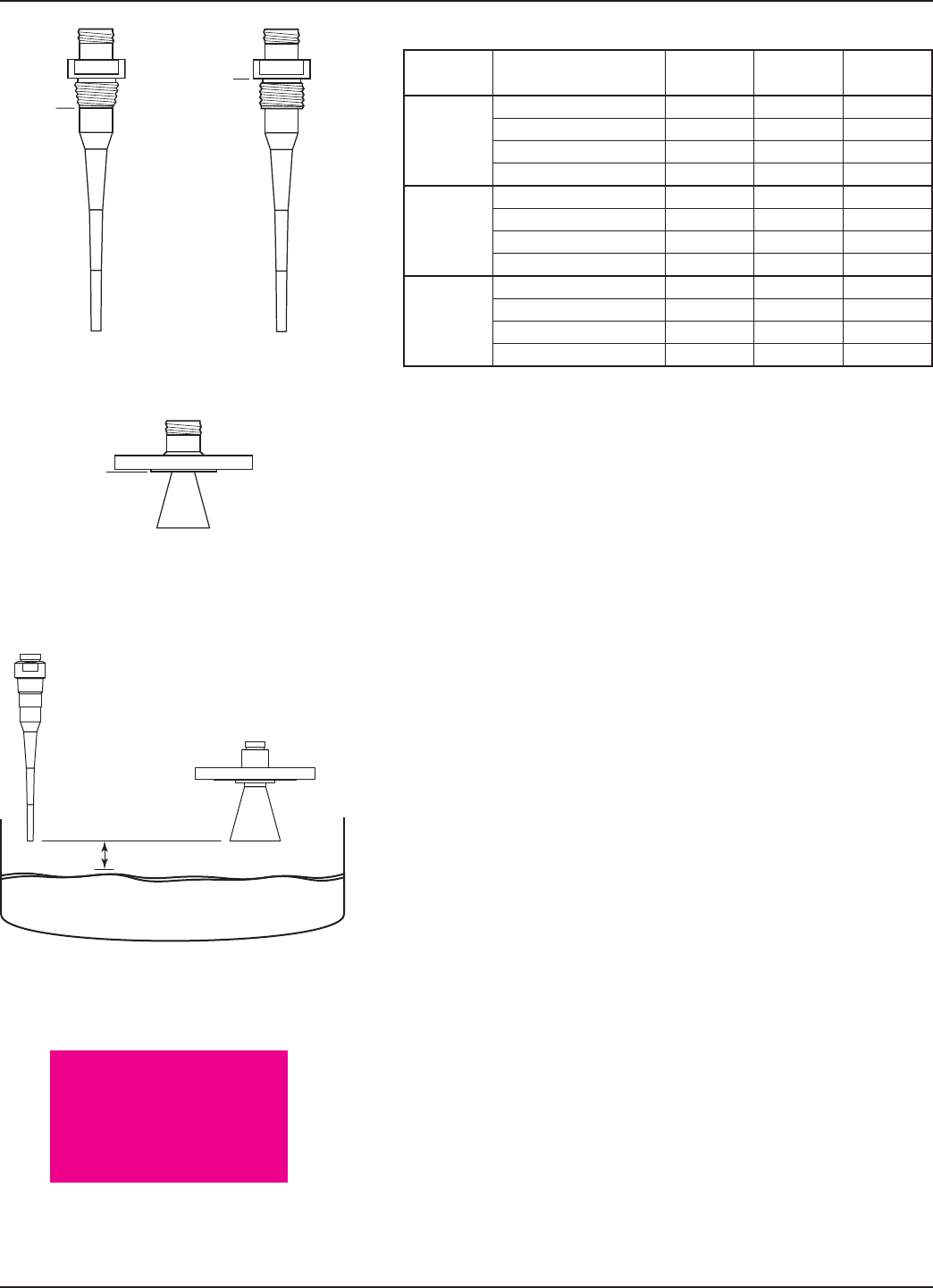
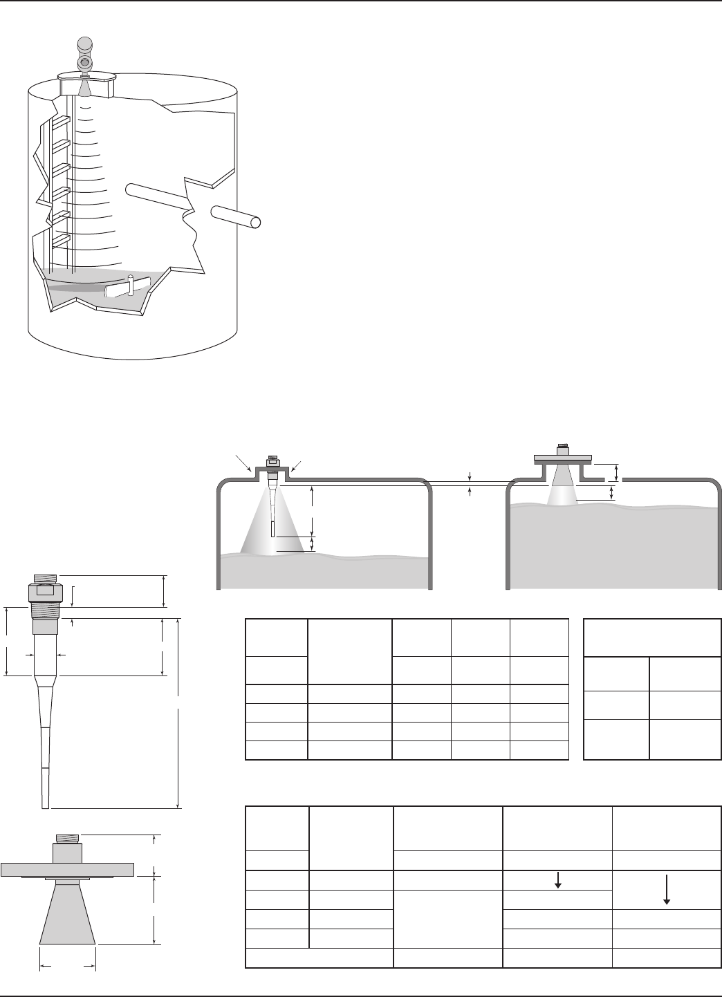
2.4.1.4 Nozzles
Improper installation in a nozzle creates “ringing” that will
adversely affect measurement. The antenna should always be
mounted so the active section of the antenna is a minimum
of 0.5" (12mm) outside the nozzle. Antenna extensions are
offered to allow the PULSAR Model R96 transmitter to
work reliably in nozzles with “L” dimensions of 1" (25
mm), 4" (100mm), 8" (200mm) or 12" (300mm). Standard
antennas (no extension) are shown below for reference. See
Section 3.7.6 for dimensional drawings of all antenna
designs including nozzle extensions.
0.50" (13 mm)
Minimum
2" (50 mm)
Minimum Diameter
Dielectric Rod Antenna
Coupling
2" (50 mm)
2" (50 mm)
8" (200 mm)
Horn Antenna
Nozzle Height
" L " Dimension
2.8
(55)
0.68 (17) Thread
Engagement
A
C
B
D∅
3
(76)
H
∅
Aperture
2.2 (56) 11.1 (282) 3.0 (76)
5.1 (130) 14.0 (356) 5.9 (150)
9.1 (231) 18.0 (457) 9.9 (251)
13.1 (333) 22.0 (559) 13.9 (353)
∅ 1.625 (41)
∅1.50 (38)
∅ 1.625 (41)
2.7 (51)
N/A
4.6 (117)
8.4 (213) 8.3 (211)
12.4 (315) 12.4 (315)
2.95" (75 mm) 3.75" (95 mm) 5.75" (146 mm)
17
58-602 Pulsar®Model R96 Radar Transmitter
2.4.1.5 Standpipes and Stillwells
The PULSAR Model R96 can be mounted in a standpipe
or stillwell but certain items must be considered:
• Metal stillwells only: Sizes 3–8 inches (80–200 mm).
(Beyond 8", effects are negligible.)
• Diameter must be consistent throughout length; no reducers.
• Use only horn antennas sized to pipe ID; 3–6" (80–
150mm); 8" pipe can use a 6" horn.
• Stillwell length must cover complete range of measurement
(i.e., liquid must be in stillwell).
• Welds should be smooth.
• Vents: holes <0.5" diameter, slots <0.5" width.
• If an isolation valve is used, it must be a full port ball valve
with an I.D. equal to the pipe diameter.
• Bridles/Bypass Installations: The launcher (index mark)
should be rotated 90° from process connections.
• Configuration must include an entry for the PIPE I.D
parameter. See Section 2.6.5.1, Item 35- PIPE I.D.
• There will be some increased dielectric sensitivity; system
gain will be reduced when PIPE ID >0.
• Remove the protective plastic cap from the top of antenna.
Store the cap in a safe place in case the transmitter has to be
removed later.
• Carefully place the transmitter on the antenna.
• Rotate the transmitter to face the most convenient direction
for wiring, configuration and viewing. Do not tighten the
universal connector (large hex nut) nor the set screw on the
housing base. The transmitter launcher must be oriented
properly for optimal performance.
• Do not place insulating material around any part of the
radar transmitter including the antenna flange.
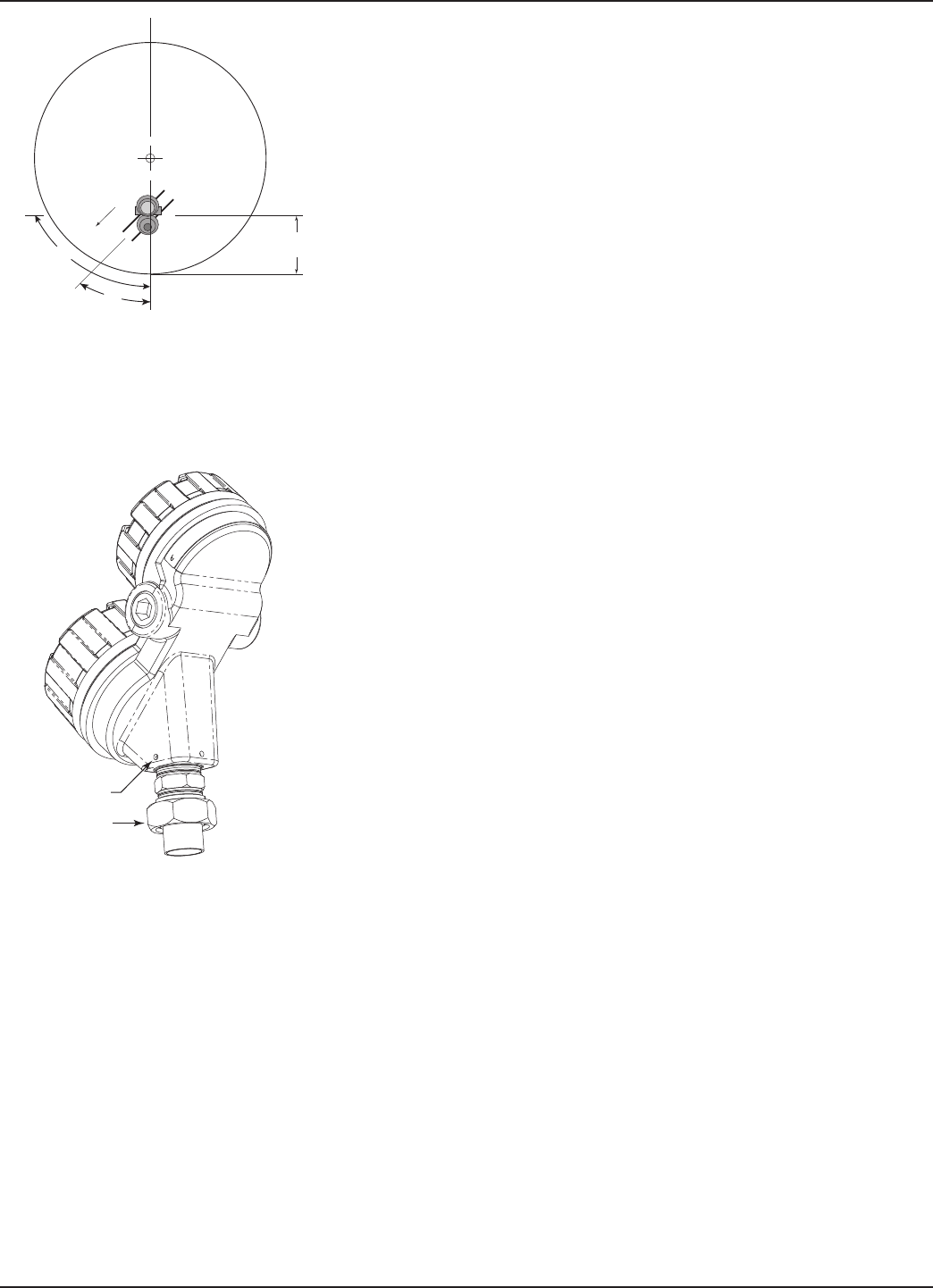
2.4.2.1 Orientation
The PULSAR Model R96 transmitter utilizes a linearly
polarized, microwave beam that can be rotated to improve
its performance. Proper orientation can minimize unwanted
target reflections, decrease sidewall reflections (multipath)
and maximize direct reflections from the liquid surface. The
index mark located on the side of the launcher is oriented in
the same direction as the polarization.
The index mark is also present for reference(1 dot: GP/IS or
2 dots: XP). The launcher is considered to be at 0° when
the index mark is closest to the tank wall. (See figures at left.)
Set Screw
Universal
Connector
Index
Mark
1 dot: GP/IS
2 dots: XP
Index
Mark
i
n
d
ex
m
a
rk
45°
18 58-602 Pulsar®Model R96 Radar Transmitter
2.4.2.2 Initial Installation
Ideally, the transmitter should be mounted half the radius
from the tank wall. Align the index mark so it is at an angle
of 45 degrees to a line from the radar unit to the nearest
tank wall. For horizontal cylindrical vessels, align the
launcher (index mark) so it is facing along the long axis of
the vessel. Once properly oriented, tighten set screws and
Universal connector (30 ft-lbs of force).
A transmitter mounted within 18" (45 cm) of a tank wall
may demand orientation adjustments to limit multipath
and optimize performance. See Section 2.4.2.3 Signal Loss.
NOTE: ALWAYS RUN THE ECHO REJECTION ROUTINE AFTER MAKING
CHANGES TO MENU CHOICES (,
) or when launcher is repositioned.
2.4.2.3 Low Echo Margin
Low Echo Margin has many potential causes. Following are
two initial areas for investigation.
Launcher Orientation: Initial launcher orientation is always
45 degrees (see Sections 2.4.1 & 2.4.2). In tall vessels and
when antenna is mounted close to the tank wall, improve-
ment in Echo Margin (signal quality) may be attained by
rotating the launcher to 90 degrees.
Echo Loss: If the Level signal is lost repeatedly at a specific
point in the vessel, it is usually a symptom that multipath
(side-wall) reflections are causing cancellation by returning
to the transmitter exactly 180° out of phase with the actual
Level signal. This can be improved by utilizing the follow-
ing procedure:
• Scroll to Display Config Menu under Device Setup. This
menu shows both Level and Echo Margin.
• Bring the Level up (or down) to the exact point where the
signal is repeatedly lost. Monitor the Echo Margin value as
this point is being approached. The Echo Margin value will
degrade to a low point before it begins to increase.
• When the Echo Margin reaches this low point, loosen both
the Universal connector and the set screw. Slowly rotate the
launcher clockwise approximately 10–20° (the transmitter
can be rotated independently). Allow the unit to stabilize
for approximately 1 minute. Repeat this process until the
Echo Margin value is optimized.
• Without disturbing the position of the launcher, position
the transmitter head back to its most convenient location.
• Tighten both the Universal connector (30 ft-lbs of force) and
Launcher set screw.
1/2 Radius
Launcher
Index mark
(facing 45°)
45°
90°
Set Screw
Universal
Connector
TBD
19
58-602 Pulsar®Model R96 Radar Transmitter
Red (+)
Black (-)
(+)
(-)
NOTE: ALWAYS RUN THE TARGET REJECTION ROUTINE AFTER
MAKING CHANGES TO MENU CHOICES ( ,
) or
when launcher is repositioned.
2.5 Wiring
HART versions of the PULSAR Model R96 transmitter
operate at voltages of 11–36 VDC, while FOUNDATION field-
bus versions operate at 9–17.5 VDC. Higher voltages will
damage the transmitter.
Wiring connections between the power supply and the
PULSAR Model R96 Radar Transmitter should be made
using 18–22 AWG shielded twisted pair instrument cable.
Connections are made to the terminal strip and the
ground connections within the top enclosure compartment.
The directions for wiring the PULSAR Model R96 trans-
mitter depend on the application:
• General Purpose or Non-Incendive (Cl I, Div. 2)
• Intrinsically Safe
• Explosion Proof
WARNING! Explosion hazard. Do not disconnect equipment unless
power has been switched off or the area is known to be
non-hazardous.
A general purpose installation does not have flammable
media present.
Areas rated Non-Incendive (Cl I, Div. 2) have flammable
media present only under abnormal conditions.
No special electrical connections are required.
If flammable media is contained in the vessel, the trans-
mitter must be installed per Class I, Div 1 standards of
area classification.
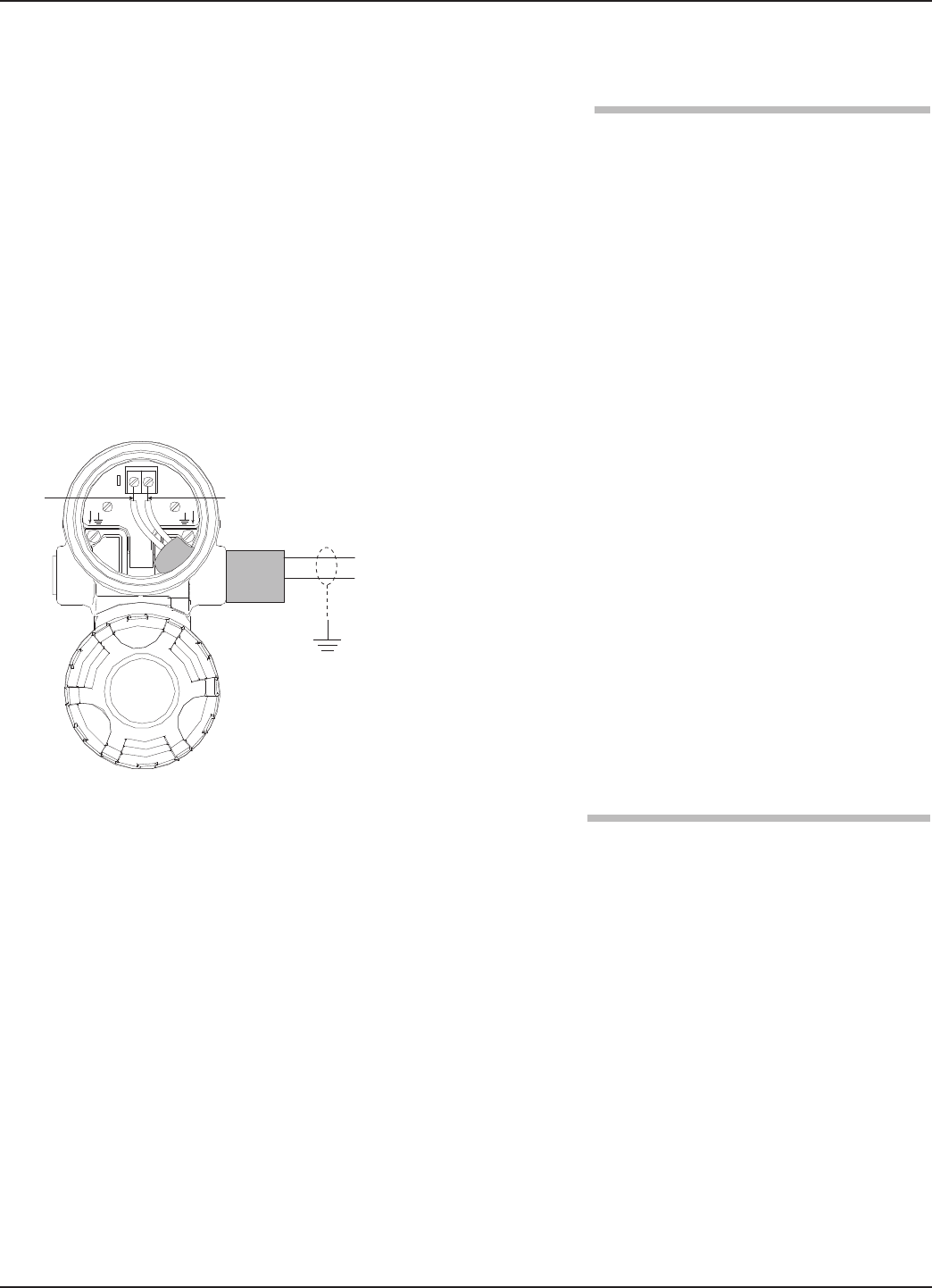
To install General Purpose or Non-Incendive wiring:
1. Remove the cover from the wiring compartment of the
transmitter. Install the conduit plug in the unused opening
and use PTFE tape/sealant to ensure a liquid-tight connec-
tion.
2. Install a conduit fitting and pull the supply wires.
3. Connect shield to an earth ground at power supply.
4. Connect an earth ground wire to the nearest green ground
screw (not shown in illustration).
5. Connect the positive supply wire to the (+) terminal and
the negative supply wire to the (-) terminal.
20 58-602 Pulsar®Model R96 Radar Transmitter
6. Replace and tighten the cover to the transmitter wiring
compartment before applying power.
An Intrinsically Safe (IS) installation potentially has flam-
mable media present. An approved IS barrier must be
installed in the non-hazardous (safe) area to limit the avail-
able energy out to the hazardous area.
See Agency Drawing – Intrinsically Safe Installation,
Section 3.5.1.
To install Intrinsically Safe wiring:
1. Ensure that the IS barrier is properly installed in the safe
area (refer to local plant or facility procedures). Complete
the wiring from the power supply to the barrier and from
the barrier to the PULSAR Model R96 transmitter.
2. Remove the cover from the wiring compartment of the
transmitter. Install the conduit plug in the unused opening
and use PTFE tape/sealant to ensure a liquid-tight
connection.
3. Install a conduit fitting and pull the supply wires.
4. Connect shield to an earth ground at power supply.
5. Connect an earth ground wire to the nearest green ground
screw (not shown in illustration).
6. Connect the positive supply wire to the (+) terminal and
the negative supply wire to the (-) terminal.
7. Replace and tighten the cover to the wiring compartment
of the transmitter before applying power.
Explosion Proof (also referred to as XP or flameproof) is
another method of designing equipment for installation
into hazardous areas. A hazardous location is an area in
which flammable gases or vapors are (or may be) present
in the air in quantities sufficient to produce explosive or
ignitable mixtures.
The wiring for the transmitter must be contained in
Explosion Proof conduit extending into the safe area.
• Due to the specialized design of the PULSAR MODEL
R96 transmitter, no Explosion Proof conduit fitting (EY
seal) is required within 18" of the transmitter.
• An Explosion Proof conduit fitting (EY seal) is required
between the hazardous and safe areas. See Agency
Specifications, Section 3.5.
Red (+)
Black (-)
(+)
(-)
21
58-602 Pulsar®Model R96 Radar Transmitter
To install an Explosion Proof transmitter:
1. Install Explosion Proof conduit from the safe area to the
conduit connection of the PULSAR Model R96 transmit-
ter (refer to local plant or facility procedures).
2. Remove the cover from the wiring compartment of the
transmitter.
3. Connect shield to an earth ground at the power supply.
4. Connect an Earth ground wire to the nearest green ground
screw per local electrical code (not shown in illustration).
5. Connect the positive supply wire to the (+) terminal and
the negative supply wire to the (-) terminal.
6. Replace and tighten the cover to the wiring compartment
of the transmitter before applying power.
2.6 Configuring the Transmitter
Although the PULSAR Model R96 transmitter can be
delivered pre-configured from the factory, it can also be
easily reconfigured in the shop or at the installation using
the local LCD/Keypad or PACTware/DTM. Bench config-
uration provides a convenient and efficient way to set up
the transmitter before going to the tank site to complete
the installation.
Before configuring any transmitter, collect all operating
parameters information (refer to Section 1.1.2).
Apply power to the transmitter and follow the step-by-step
procedures for the menu-driven transmitter display. Refer
to Sections 2.6.2 and 2.6.4.
Information on configuring the transmitter using a HART
communicator is given in Section 2.7, Configuration
Using HART.
Please refer to I/O manual 58-640 for information on
FOUNDATION fieldbus output.
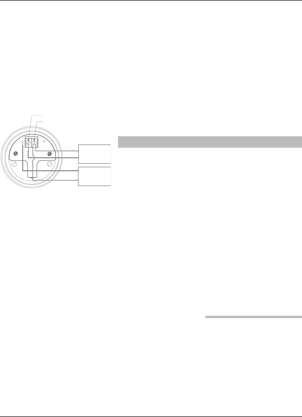
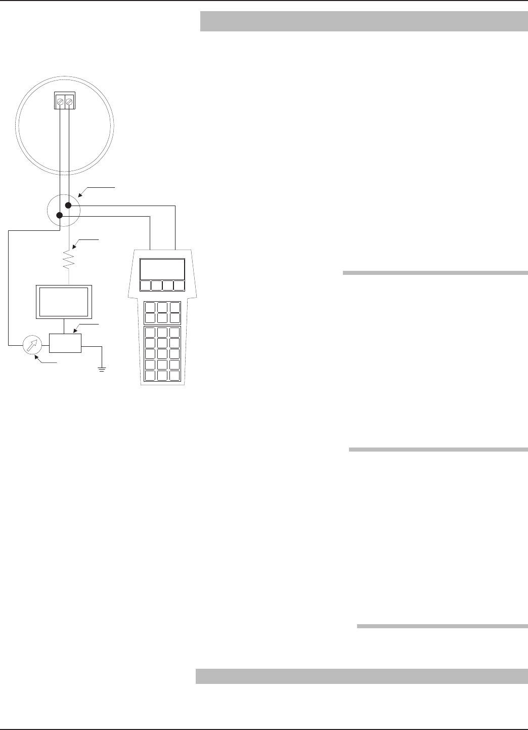
The PULSAR Model R96 transmitter can be easily config-
ured at a test bench by connecting a standard 24 VDC
power supply directly to the transmitter terminals as
shown in the accompanying diagram. An optional digital
multimeter is shown in the event that mA current meas-
urements are desired.
NOTE: Current measurements taken at these test points are an
approximate value. Accurate current readings should be
taken with the digital multimeter directly in series with the
loop.
+
–
Power Supply
24 VDC
–
+
(–) negative
(+) positive
Test
Current Meter
22 58-602 Pulsar®Model R96 Radar Transmitter
NOTE: When using a HART communicator for configuration, a mini-
mum 250-ohm line load resistance is required. Refer to your
HART communicator manual for additional information.
NOTE: The transmitter can be configured without the antenna
attached. Disregard any diagnostic indicators that may
appear.
The four push buttons offer various forms of functionality
for navigation and data entry.
The PULSAR Model R96 user interface is hierarchical in
nature, best described as a tree structure. Each level in the
tree contains one or more items. Items are either menu
labels or parameter names.
• Menu labels are presented in all capital letters
• Parameters are capital words
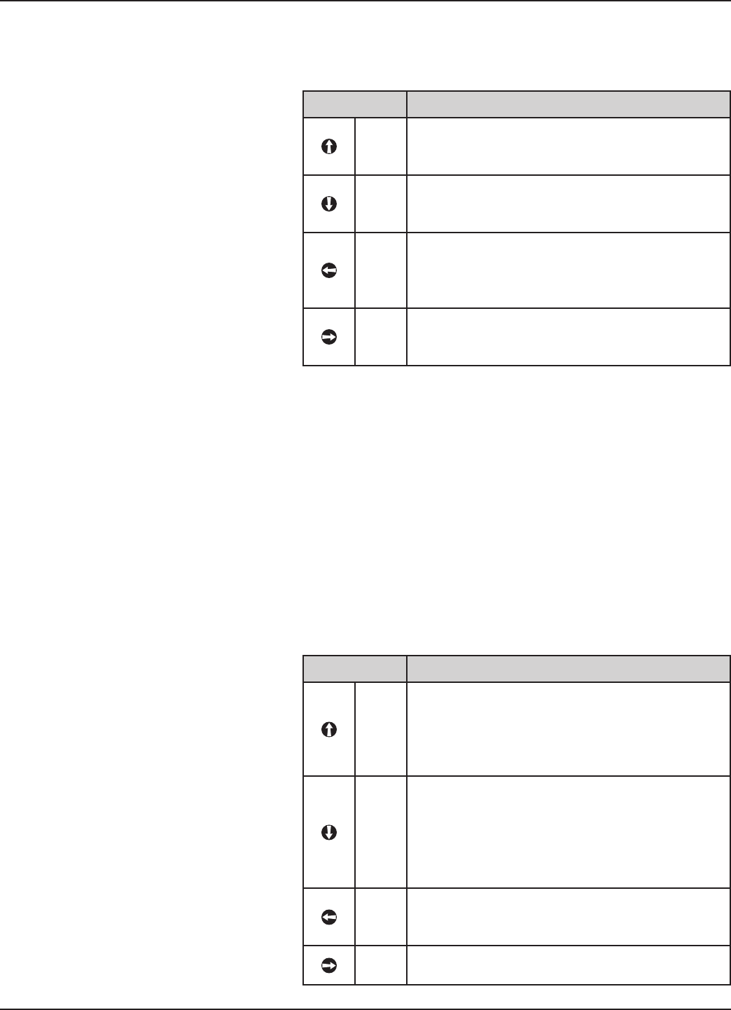
2.6.2.1 Navigating the Menu
UP moves to the previous item in the menu branch.
DOWN moves to the next item in the menu branch.
BACK moves back one level to the previous (higher)
branch item.
ENTER enters into the lower level branch or switches
to the entry mode. Holding the ENTER down on any
highlighted menu name or parameter will show help
text for that item.
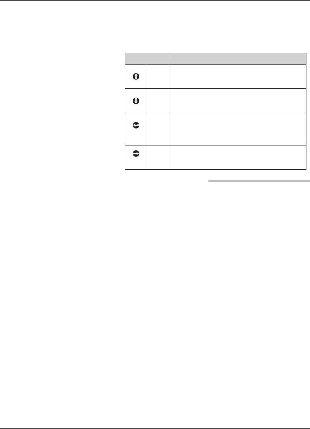
2.6.2.2 Data Selection
This method is used for selecting configuration data from
a specific list.
UP and DOWN to navigate the menu and high-
light the item of interest
ENTER allows modification of that selection
UP and DOWN to choose new data selection
ENTER to confirm selection
Use BACK (Escape) key at any time to abort the pro-
cedure and escape to previous branch item
➪
➪
➪
➪
➪
➪
➪
➪
➪
➪
➪
Up Down Back Enter
+
–
+
–
Power Supply
24 VDC
(-) negative
(+) positive
Test
Current Meter
FPO
23
58-602 Pulsar®Model R96 Radar Transmitter
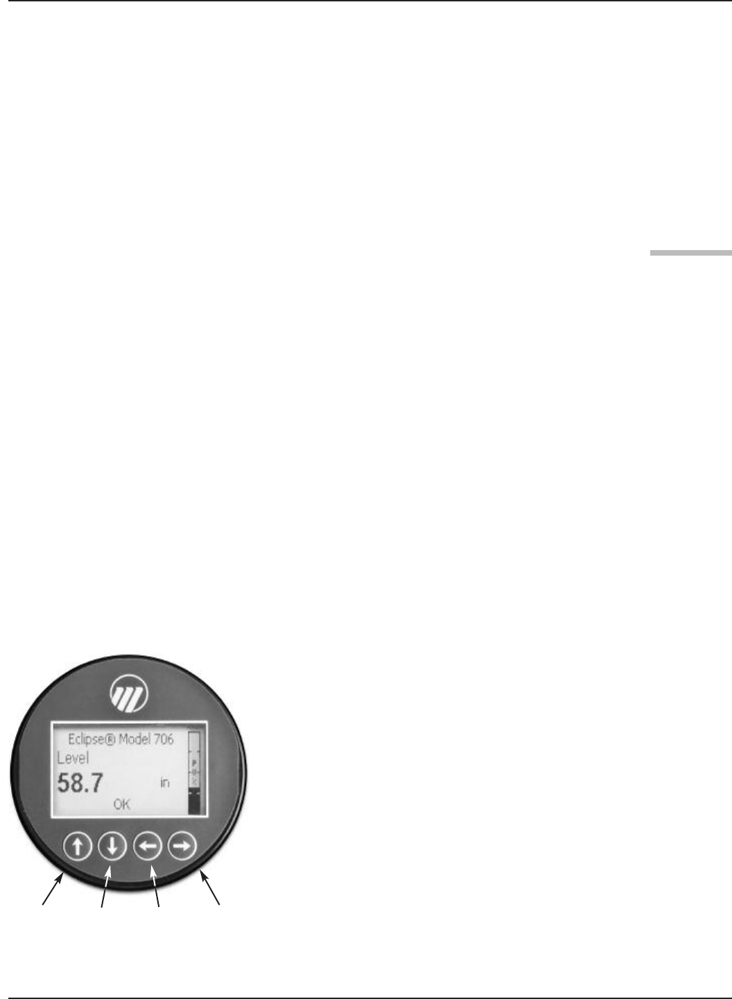
2.6.2.3 Entering Numeric Data Using Digit Entry
This method is used to input numeric data, e.g., Tank
Height, set 4 mA and set 20 mA.
All numeric values are left-justified, and new values are
entered from left to right. A decimal point can be
entered after the first digit is entered, such that .9 is
entered as 0.9.
Some configuration parameters can have a negative
value. In this case, the leftmost position is reversed for
the sign (either "-" for a negative value, or "+" for a pos-
itive value).
2.6.2.4 Entering Numeric Data Using Increment/Decrement
Use this method to input the following data into
parameters such as Damping and Failure Alarm.
Push button Keystroke Action
Up
Moves up to the next highest digit (0,1,2,3,....,9
or decimal point). If held down the digits scroll
until the push button is released.
Down
Moves up to the next lowest digit (0,1,2,3,....,9 or
decimal point). If held down the digits scroll until
the push button is released.
Back
Moves the cursor to the left and deletes a digit. If
the cursor is already at the leftmost position,
then the screen is exited without changing the
previously saved value.
Enter
Moves the cursor to the right. If the cursor is
located at a blank character position, the new
value is saved.
Push button Keystroke Action
Up
Increments the displayed value. If held down
the digits scroll until the push button is released.
Depending on which screen is being revised, the
increment amount may increase by a factor of 10
after the value has been incremented 10 times.
Down
Decrements the displayed value. If held down the
digits scroll until the push button is released.
Depending on which screen is being revised, the
decrement amount may increase by a factor of
10 after the value has been decremented 10
times.
Back
Returns to the previous menu without changing
the original value, which is immediately redis-
played.
Enter Accepts the displayed value and returns to the
previous menu.
24 58-602 Pulsar®Model R96 Radar Transmitter
2.6.2.5 Entering Character Data
This method is used for parameters requiring alphanumeric
character entry, such as for entering tags, etc.
General Menu Notes:
The PULSAR MODEL R96 Model R96 transmitter has
three levels of password protection to restrict access to cer-
tain portions of the menu structure that affect the operation
of the system. The user password can be changed to any
numerical value up to 59999. When the transmitter is pro-
grammed for
password protection, a password is required whenever
configuration values are changed.
User Password
The User Password allows the customer to limit access to
the basic configuration parameters.
The default User Password installed in the transmitter at
the factory is 0. With a password of 0, the transmitter is no
longer password protected and any value in the basic user
menus can be adjusted without entering a confirming
password.
NOTE: If a User Password is not known or has been misplaced, the
menu item New Password in the DEVICE SETUP/ADVANCED
CONFIG menu displays an encrypted value representing the
present password. Contact Technical Support with this
encrypted password to retrieve the original User Password.
Push button Keystroke Action
Up
Moves to the previous character (Z...Y...X...W).
If held down, the characters scroll until the push
button is released.
Down
Moves to the next item character (A...B...C...D).
If held down, the characters scroll until the push
button is released.
Back
Moves the cursor back to the left. If the cursor is
already at the leftmost position, then the screen
is exited without changing the original tag char-
acters.
Enter
Moves the cursor forward to the right. If the
cursor is at the rightmost position, then the
new tag is saved.
25
58-602 Pulsar®Model R96 Radar Transmitter
Advanced Password
Certain portions of the menu structure that contain more
advanced parameters are further protected by an Advanced
Password.
This password will be provided, when necessary, by Factory
technical support.
Factory Password
Calibration-related and other factory settings are further
protected by a Factory Password.
The following tables provide a complete explanation of the
software menus displayed by the PULSAR Model R96
transmitter. The menu layout is similar between the local
Keypad/LCD interface, the DD, and the DTM.
Use these tables as a step-by-step guide to configure the
transmitter based on the desired measurement type from the
following selections:
• Level Only
• Level & Volume
HOME SCREEN
The Home Screen consists of a “slide show” sequence of
Measured Values screens which are rotated at 2-second
intervals. Each Home Measured Value screen can present up
to four information items:
• HART®Tag
• Measured Value
Label, Numerical Value, Units
• Status
Will be displayed as text or optionally with NAMUR
NE 107 symbol
• Primary Value Bar Graph (shown in %)
The Home Screen presentation can be customized by view-
ing or hiding some of these items. See DISPLAY CONFIG
under the DEVICE SETUP menu in Section 2.6.5 —
Configuration Menu.
At left is an example of a Home Screen for a Model R96
configured for a Level Only application.
Up Down Back Enter
FPO
26 58-602 Pulsar®Model R96 Radar Transmitter
MAIN MENU
Pressing any key on the Home Screen will present the Main
Menu, consisting of three basic menu labels shown in all
capital letters.
• DEVICE SETUP
• DIAGNOSTICS
• MEASURED VALUES
As shown, the reverse video represents a cursor identifying
the selected item, which will appear in reverse video on the
LCD. The actions of the keys at this point are:
NOTES: 1. Items and parameters that are shown in lower level menus
will depend on the Measurement Type chosen. Those
parameter not applicable to the present Measurement Type
will be hidden.
2. Holding down the Enter key when the cursor is highlighted
over a parameter or menu will provide additional information
about that item.
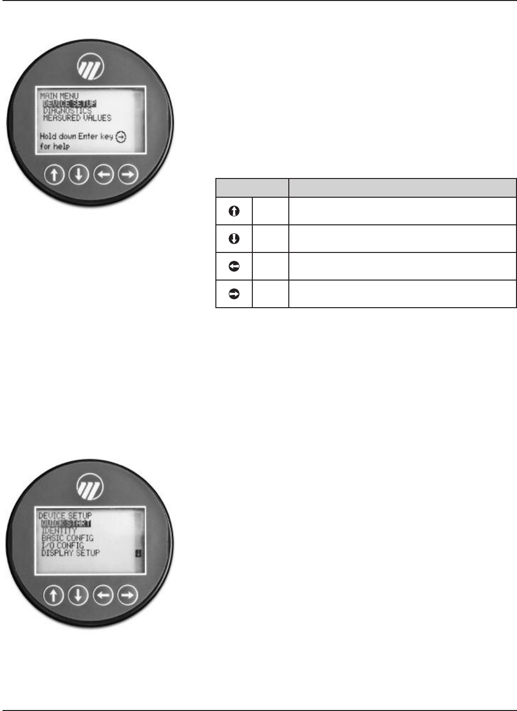
DEVICE SETUP
Choosing DEVICE SETUP from the MAIN MENU will
result in an LCD presentation as shown at left.
The small down arrow shown at the right hand side of the
screen is the indication that more items are available below
and can be accessed by pressing the DOWN key.
Section 2.6.5 shows the entire tree menu for the Model R96
DEVICE SETUP Menu.
DIAGNOSTICS
Refer to Section 3.3.4
MEASURED VALUES
Allows the user to scroll through all of the available
measured values for the measurement type chosen.
Push button Keystroke Action
Up No action as the cursor is already at the first
item in the MAIN MENU
Down Moves the cursor to DIAGNOSTICS
Back Moves back to HOME SCREEN, the level
above MAIN MENU
Enter Presents the selected item, DEVICE SETUP
27
58-602 Pulsar®Model R96 Radar Transmitter
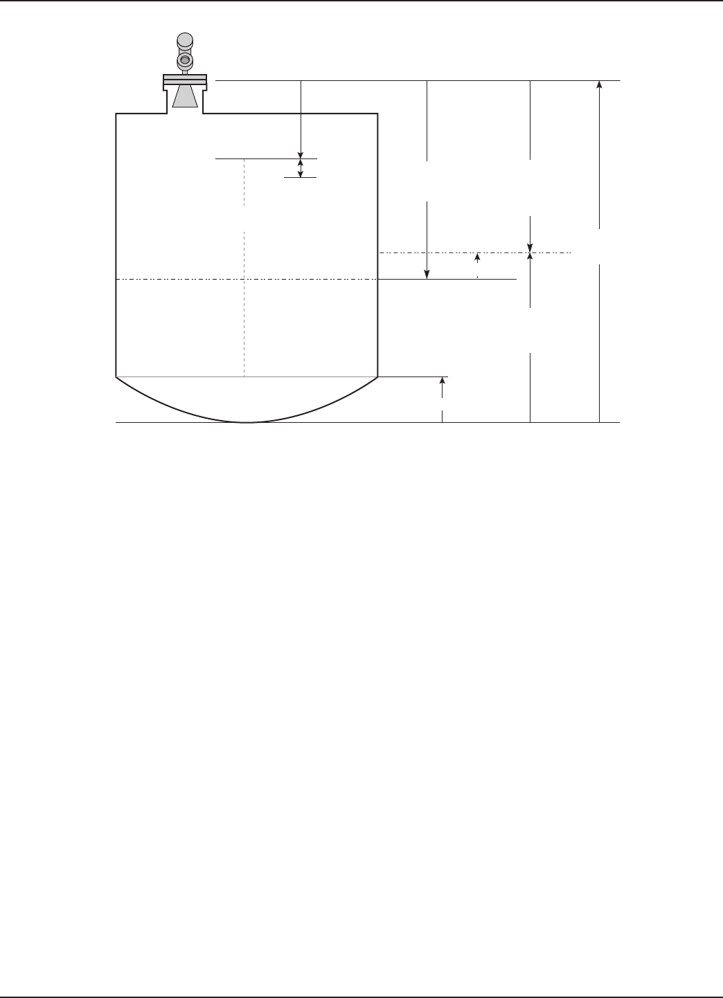
Tank
Height
Sensor Reference Point
Top Blocking
Distance
Safety Zone
Bottom Blocking Distance
Measurement
Region
Sensor
Level
Distance
Sensor
Level
Distance
– Level Trim
Level = Tank Height –
(Sensor Level Distance
– Level Trim)
Level Trim

28 58-602 Pulsar®Model R96 Radar Transmitter
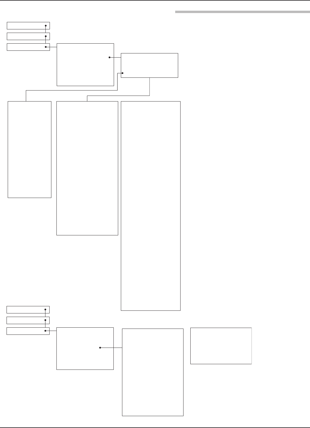
HomeScreen
Main Menu
Device Setup Quick Start
Identity
BasicConfig
Display Config
AdvancedConfig
FactoryConfig
Level Units:
Inches
Feet
Millimeters
Centimeters
Meters
Tank Height
24 inches to 130 feet
(60 cm to 40 m)
Antenna Model:
RAA-x TFE Rod
RAB-G PolyP Rod
RAB-L PolyP Rod
RAB-x PolyP Rod
RAC-x Halar Rod
RA3 3" Horn
RA4 4" Horn
RA6 6" Horn
Antenna Mount:
NPT
BSP
Flange
Antenna Extension:
-0** nozzle up to 1"
-1** nozzle up to 4"
-2** nozzle up to 8"
-3** nozzle up to 12"
Dielectric Range:
4 mA Set Point (LRV):
-25 feet to 130 feet
(-7.6 m to 30 m)
20 mA Set Point (URV):
-25 feet to 130 feet
(-7.6 m to 30 m)
1.7to3.0
3.0 to 10
Above 10
Antenna Mount:
NPT
BSP
Flange
Stillwell I.D.:
3 to 6 inches
75 to 150 mm
Turbulance:
None
Light
Medium
Heavy
Foam:
None
Light
Medium
Heavy
Dielectric Range:
1.7 to 3.0
3.0 to 10
Above 10
HomeScreen
Main Menu
Device Setup Quick Start
Identity
BasicConfig
Model (read only)
Magnetrol S/N (read only)
Hardware Version (read only)
Firmware Version (read only)
Long Tag
Measurement Type:
LevelOnly
SystemUnits
Volume and Level
System Units:
Inches
Feet
Millimeters
Centimeters
Meters
I/O Config
Failure Alarm:
22 mA
3.6 mA
HOLD
Antenna Model:
RAA-x TFE Rod
RAB-G PolyP Rod
RAB-L PolyP Rod
RAB-x PolyP Rod
RAC-x Halar Rod
RA3 3" Horn
RA4 4" Horn
RA6 6" Horn
Antenna Extension:
-0** nozzle up to 1"
-1** nozzle up to 4"
-2** nozzle up to 8"
-3** nozzle up to 12"
Rate of Change:
< 5 in/min
5-20 in/min
20-60 in/min
> 60 in/min
Display Config
AdvancedConfig
FactoryConfig
I/O Config
ECHO REJECTION:
View Echo Curve
View Reject Curve
Echo List Mode
Level
Distance
Live Echo List
Rejected Echo List
Reject Curve End
Echo Reject State
Disabled
Enabled
NEW REJECT CURVE
Select Target Echo
New Rej Curve End
Save Reject Curve
Tank Height:
24 inches to 130 feet
(60 cm to 40 m)
29
58-602 Pulsar®Model R96 Radar Transmitter
HomeScreen
Main Menu
Device Setup Quick Start
Identity
BasicConfig
Display Config
AdvancedConfig
FactoryConfig
Measurement Type:
LevelOnly
SystemUnits
Volume and Level
Dielectric Range:
1.7to3.0
3.0to10
Above 10
Volume Units:
Cubic Feet
Cubic Inches
Gallons
Milliliters
Liters
Vessel Type:
Rectangular
Horizontal/Flat
Horizontal/Elliptical
Horizontal/Spherical
Spherical
Vertical/Flat
Vertical/Elliptical
Vertical/Spherical
Vertical/Conical
Custom Table
Vessel Dimensions:
(not used with Custom Table)
Width
Length
Level Units:
Inches
Feet
Millimeters
Centimeters
Meters
Antenna Mount:
NPT
BSP
Flange
Tank Height:
24 inches to 130 feet
(60 cm to 30 m)
Stillwell I.D.:
3 to 6 inches
(75 to 150 mm)
Turbulance:
None
Light
Medium
Heavy
Foam:
None
Light
Medium
Heavy
Volume Config
I/O Config
Antenna Model:
RAA-x TFE Rod
RAB-G PolyP Rod
RAB-L PolyP Rod
RAB-x PolyP Rod
RAC-x Halar Rod
RA3 3" Horn
RA4 4" Horn
RA6 6" Horn
Barrels
Antenna Extension:
-0** nozzle up to 1"
-1** nozzle up to 4"
-2** nozzle up to 8"
-3** nozzle up to 12"
Rate of Change:
< 5 in/min
5-20 in/min
20-60 in/min
> 60 in/min
ECHO REJECTION:
View Echo Curve
Echo List Mode
Level Distance
Live Echo List
Reject Curve End
Echo Rej State
Disabled
Enabled
New Reject Curve
Select Target Echo
New Reject Curve End
Save Reject Curve
HomeScreen
Main Menu
Device Setup Quick Start
Identity
Display Config
Volume Config
I/O Config
Custom Table Setup:
Custom Table Type:
Linear
Spline
Sensor Offset
Quick Start
Basic Config
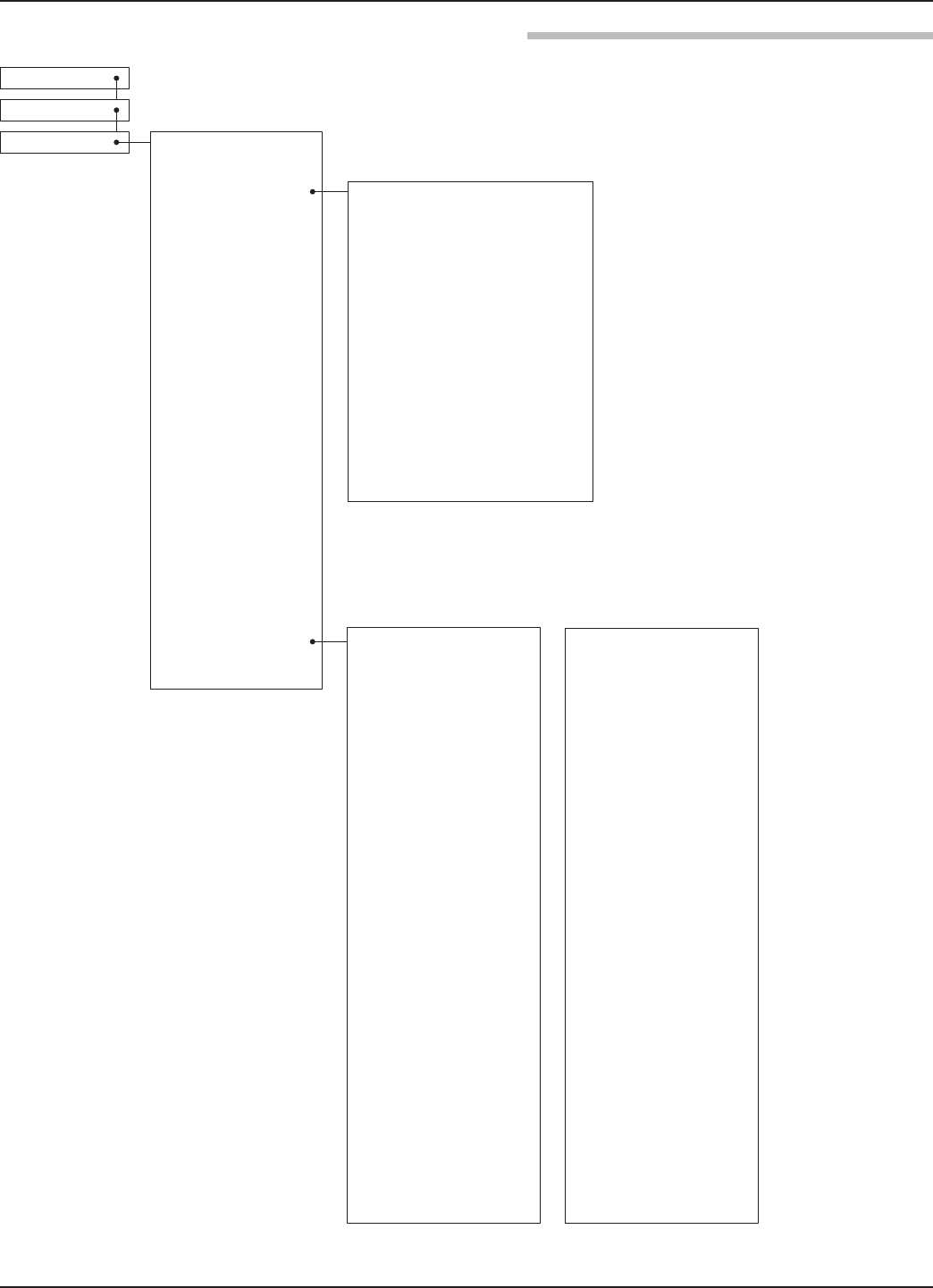
30 58-602 Pulsar®Model R96 Radar Transmitter
Home Screen
Main Menu
Device Setup Quick Start
Identity
Basic Config
I/O Config
Display Config
Advanced Config
Factory Config
Primary Variable
4 mA Set Pt (LRV):
-25 feet to 130 feet
(-7.6 m to 30 m)
0 to 9999999 gals (Volume)
20 mA Set Pt (URV):
-25 feet to 130 feet
(-7.6 m to 30 m)
0 to 9999999 cf (Volume)
Failure Alarm:
22 mA
3.6 mA
Hold
Damping:
0 to 10 seconds
Language:
English
French
German
Spanish
Russian
Portuguese
Status Symbol:
Hide
View
Long Tag:
Hide
View
PV Bar Graph:
Hide
View
Level:
Hide
View
Volume:
(Volume and Level mode only)
Hide
View
Distance:
Hide
View
% Output:
Hide
View
Loop Current:
Hide
View
Echo Strength:
Hide
View
Echo Margin:
Hide
View
Elec Temp:
Hide
View

31
58-602 Pulsar®Model R96 Radar Transmitter
Home Screen
Main Menu
Device Setup Quick Start
Identity
Basic Config
I/O Config
Display Config
Advanced Config
Factory Config
Sensitivity:
0 to 100 echo strength units
Top Blocking Distance:
-7.5 to +100 feet
(-2 m to 30 m)
Bottom Blocking Distance:
-7.5 to +100 feet
(-2 m to 30 m)
SAFETY ZONE SETTINGS
Safety Zone Alarm:
None
3.6 mA
22 mA
Latched 3.6 mA
Latched 22 mA
Safety Zone Height:
(not used when Safety Alarm is
None)
2 inches to 100 feet
(5 cm to 30 m)
Reset SZ Alarm
(used when Safety Alarm is Latch
3.6 mA or Latch 22 mA)
ECHO LOSS SETTINGS:
Echo Loss Alarm:
Hold
3.6 mA
2.2 mA
Echo Loss Delay:
? to ? seconds
Failure Alarm Delay:
0 to 5 seconds
Level Trim:
-2.00 to + 2.00 feet
(-0.6 m to + 0.6 m)
THRESHOLD SETTINGS
Target Selection:
First Echo
Largest Echo
Target Thresh Mode:
Automatic
Fixed Value
Target Thresh Value:
Max (44%)
High (25%)
Med (16%)
Low (11%)
Base Threshold:
0–99 ESU
Time Variable Gain:
TVG Start Value
TVG End Value
TVG Start Locn
# Run Average
Max Surface Velocity
Max Distance Jump
Empty State Delay
ANALOG OUTPUT:
HART Poll Address:
0 to 63
Loop Current Mode:
Disabled (Fixed)
Enabled (PV)
[Fixed Current Value]
4 to 20 mA
ADJUST ANALOG
OUTPUT:
Adjust 4mA
Adjust 20mA
New User Password:
0 to 59,999
CONFIG CHANGED:
Indicator Mode:
Disabled
Enabled
Reset Config Chngd:
Reset?
No
Yes
Reset Parameters:
No
Yes

32 58-602 Pulsar®Model R96 Radar Transmitter
Home Screen
Main Menu
Device Setup Quick Start
Identity
Basic Config
I/O Config
Display Config
Advanced Config
Factory Config SZ Hysteresis (Safe Zone Hysteresis):
(not used when Safe Zone Alarm is None)
0 to 100 feet
(0 to 30 m)
New Advanced Password Value
Factory Reset
FIDUCIAL ADJUSTMENT
Fiducial Gain:
0 to 255 (read only)
Fiducial Stength
TVG Start Location
Window
Fiducial Ticks
FACTORY CALIB
(Factory password required)
Elec Temp Offset
Conversion Factor
Scale Offset
Tug Divisor
33
58-602 Pulsar® Model R96 Radar Transmitter
2.7 Configuration Using HART®
A HART (Highway Addressable Remote Transducer)
remote unit, such as a HART communicator, can be used to
provide a communication link to the PULSAR Model R96
transmitter. When connected to the control loop, the same
system measurement readings shown on the transmitter are
also shown on the communicator. The communicator can
also be used to configure the transmitter.
The HART communicator may need to be updated to
include the PULSAR Model R96 software (Device
Descriptions). Refer to your HART Communicator Manual
for update instructions.
One can also access configuration parameters using
PACTware and the Model R96 DTM, or using the AMS
with EDDL.
A HART communicator can be operated from a remote
location by connecting it to a remote junction or by con-
necting it directly to the terminal block in the electronics
housing of the PULSAR Model R96 transmitter.
HART uses the Bell 202 frequency shift key technique of
high-frequency digital signals. It operates on the 4–20 mA
loop and requires 250 Ωload resistance. A typical connec-
tion between a communicator and the PULSAR Model R96
transmitter is illustrated.
A typical communicator display is an 8-line by 21-character
LCD. When connected, the top line of each menu displays
the model (Model RX5) and its tag number or address. For
detailed operating information, refer to the instruction
manual provided with the HART communicator.
The PULSAR Model R96 transmitter online menu trees are
shown in the following illustration. Open the menu by
pressing the alphanumeric key 4, Device Setup, to display
the second-level menu.
2.7.3.1 Model R96
Dev V1 DD1 December 2015 Version 1.0a and later
+
-
Junction
RL > 250 Ω
Control
Room
Display
Power
Supply
Current
Meter
34 58-602 Pulsar® Model R96 Radar Transmitter
1 View Echo Curve
2 View Reject Curve
3 Echo List Mode (Level / Distance)
4 Live Echo List
5 Rejected Echo List
6 Reject Curve End
7 Echo Reject State (Off / Disabled / Enabled)
8 New Reject Curve
1 PV
2 PV Loop Current
3 PV % Range
4 Device Setup
5 Setup Wizard
6 Diagnostics
7 Measured Values
1 Level
2 Volume
3 Distance
4 Echo Strength
5 Temperature
1 Identity
2 Basic Config
3 Volume Config
4 I/O Config
5 Local Display Config
6 Advanced Config
7 Factory Config
1 Enter Password
2 PV is
3 PV AmA Set Point
4 PV 20mA Set Point
5 PV Failure Alarm
6 Damping
7 I/O Config Diagram
8 Variable Selection
9 Set Points
1 Manufacturer
2 Product Name
3 Magnetrol S/N
4 Hardware Version
5 Firmware Version
6 ConfigChg Counter
7 Final Assy Number
8 Device ID
9 Universal Revision
10 Field Device Revision
11 Software Revision
12 Num Preambles
1 Enter Password
2 Volume Units
3 Vessel Type
4 Length
5 Width
6 Radius
7 Ellipse Depth
8 Conical Height
9 Table Type
10 Vessel Diagrams
11 Custom Table Type
12 Level Input Source
13 Custom Table Length
14 Custom Table
1 SV is
2 TV is
3 QV is
1 Lvl 4mA Set Point
2 Lvl 20mA Set Point
3 Vol 4mA Set Point
4 Vol 20mA Set Point
1 Select Target Echo
2 New Rejct Curve End
3 Save Reject Curve
1 Enter Password
2 Tag
3 Long Tag
4 Descriptor
5 Date
6 Message
7 Date/Time/Initials
8 Factory Identity
1 Enter Password
2 Level Units
3 Antenna Model
4 Antenna Ext.
5 Probe Mount
6 Tank Height
7 Measurement Type
8 Bottom Blocking Dist.
9 Still ID
10 Dielectric Range
11 Turbulance Foam
12 Rate of Change
13 Echo Rejection
35
58-602 Pulsar® Model R96 Radar Transmitter
3.0 Reference Information
This section presents an overview of the operation of the
PULSAR Model R96 Radar Level Transmitter, information
on troubleshooting, common problems, listings of agency
approvals, lists of replacement and recommended spare
parts, and detailed physical, functional and performance
specifications.
3.1 Description
PULSAR Model R96 is a two-wire, 24 VDC, level trans-
mitter based on the concept of pulse burst radar. The elec-
tronics are housed in an ergonomic housing comprised of
two tandem compartments angled at a 45 degree angle for
ease of wiring and calibration. These two compartments
connect via a watertight feed-through.
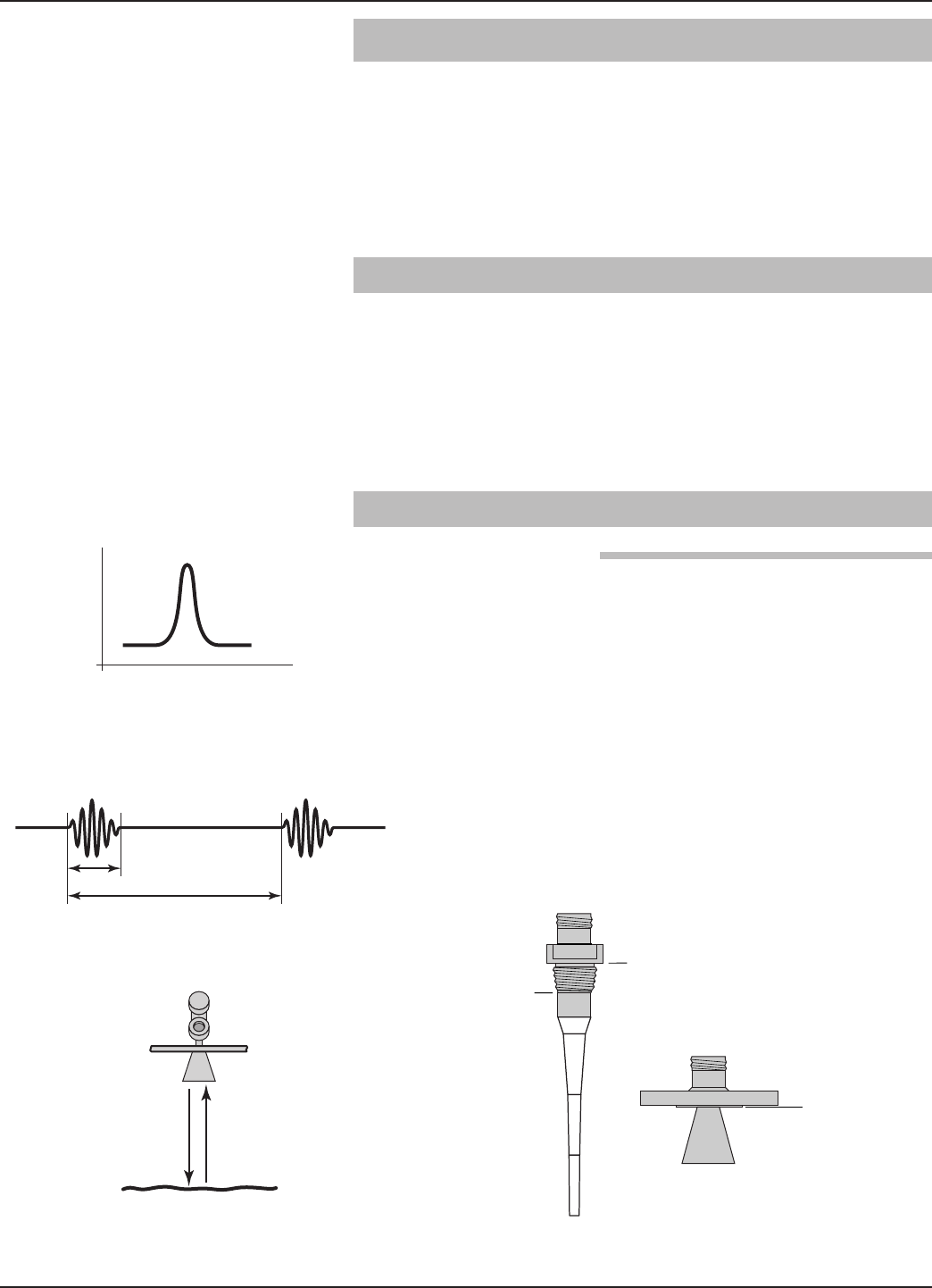
3.2 Theory of Operation
PULSAR Model R96 is a top-mounted, downward-looking
pulse burst radar operating at 6 GHz. Unlike true pulse
devices (GWR, for example) that transmit a single, sharp
(fast rise-time) waveform of wide-band energy, PULSAR
Model R96 emits short bursts of 6 GHz energy and meas-
ures the transit time of the signal reflected off the liquid
surface. Distance is calculated utilizing the equation:
Distance = C ×Transit time/2, then developing the Level
value by factoring in application-specific configuration. The
exact reference point for distance and level calculations is
the Sensor Reference Point—bottom of an NPT thread, top
of a BSP thread or face of a flange.
Distance = c × (time ÷ 2)
1 ns
500 ns
NPT
Process
Connection
BSP
Process
Connection
ANSI or DIN
Welded Flange

36 58-602 Pulsar® Model R96 Radar Transmitter
The exact level measurement is extracted from false target
reflections and other background noise via the use of
sophisticated signal processing. The new PULSAR Model
R96 circuitry is extremely energy efficient so no duty cycling
is necessary to accomplish effective measurement.
ETS, or Equivalent Time Sampling, is used to measure the
high speed, low power EM (electromagnetic) energy. ETS is
a critical key in the application of Radar to vessel level
measurement technology. The high speed electromagnetic
energy (1000 ft/µs) is difficult to measure over short dis-
tances and at the resolution required in the process industry.
ETS captures the EM signals in real time (nanoseconds) and
reconstructs them in equivalent time (milliseconds), which
is much easier to measure with today’s technology.
ETS is accomplished by scanning the tank to collect thou-
sands of samples. Approximately 3 scans are taken per sec-
ond; each scan gathers more than 50,000 samples.
37
58-602 Pulsar®Model R96 Radar Transmitter
3.3 Troubleshooting and Diagnostics
The PULSAR Model R96 transmitter is designed and engi-
neered for trouble-free operation over a wide range of oper-
ating conditions. The transmitter continuously runs a series
of internal self-tests and displays helpful messages on the
large graphic liquid crystal display (LCD) when attention is
required.
The combination of these internal tests and diagnostics
messages offer a valuable proactive method of troubleshoot-
ing. The device not only tells the user what wrong, but also,
and more importantly, offers suggestions on how to solve
the problem.
All of this information can be obtained directly from the
transmitter on the LCD, or remotely by using a HART
communicator or PACTware and the PULSAR Model R96
DTM.
PACTware™PC Program
The PULSAR Model R96 offers the ability to perform more
advanced diagnostics such as Trending and Echo Curve
analysis using a PACTware DTM. This is a powerful trou-
bleshooting tool that can aid in the resolution of any diag-
nostic indicators that may appear.
Please refer to section 4.0 “Advanced
Configuration/Troubleshooting Techniques” for additional
information.
The PULSAR Model R96 transmitter includes an exhaus-
tive list of Diagnostic Indicators which follow the NAMUR
NE 107 guidelines.
NAMUR is an international user association of automation
technology in process industries, whose goal is to promote
the interest of the process industry by pooling experiences
among its member companies. In doing so, this group
promotes international standards for devices, systems, and
technologies.
technologies.
The objective of NAMUR NE 107 was essentially to make
maintenance more efficient by standardizing diagnostics
information from field devices. This was initially integrated
via FOUNDATION Fieldbus, but the concept applies regard-
less of the communication protocol.
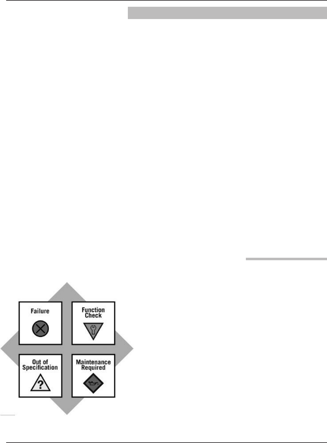
According to the NAMUR NE107 recommendation, "Self
Monitoring and Diagnosis of Field Devices," fieldbus diag-
nostic results should be reliable and viewed in the context of

38 58-602 Pulsar®Model R96 Radar Transmitter
a given application. The document recommends categorizing
internal diagnostics into four standard status signals:
• Failure
• Function Check
• Out of Specification
• Maintenance required
These categories are shown by both symbols and colors,
depending on the display capability.
In essence, this approach ensures that the correct diagnostic
information is available to the correct person-at the correct
time. In addition, it allows diagnostics to be applied, as
most appropriate, for a particular plant application (such as
process control engineering or asset management mainte-
nance). Customer specific mapping of diagnostics to these
categories allows for flexible configuration depending on the
user's requirements.
From an external Model R96 transmitter perspective, diag-
nostic information includes measurement of process condi-
tions, in addition to detection of internal device or system
anomalies.
As mentioned above, the indicators can be assignable (via
the a DTM or host system) by the user to any (or none) of
the NAMUR recommended Status Signal categories:
Failure, Function Check, Out of Specification, and
Maintenance Required.
The FOUNDATION fieldbus transmitter version of the
Model R96 was implemented according to the Field
Diagnostics Profile, which is consistent with the objectives
of NE 107.
In the FOUNDATION fieldbus version, diagnostic indicators
can be mapped to multiple categories, an example is shown
in the diagram at left.
In this example, “Calibration Required” is mapped to both
the Out of Specification and Maintenance Required status
signals, and the diagnostic indicator named “High
Temperature” is mapped to none of the signals.
Indicators that are mapped to the Failure category will nor-
mally result in a current loop alarm output. The alarm state
for HART transmitters is configurable as high (22 mA),
Low (3.6 mA), or Hold (last value).
Users will not have the ability to unassign certain indicators
from the Failure signal category as the Model R96 user
interfaces will prohibit or reject such re-assignment entries).
This is to ensure that current loop alarms are asserted in situ-
ations where the device is not able to provide measurements
Analog Output Error
Echo Lost
Calibration
Required
Failure
Function
Check
Out of
Specification
Maintenance
Required
NE-107
Status Signals
Diagnostic Indicators
High
Temperature

39
58-602 Pulsar®Model R96 Radar Transmitter
due to critical failures. (For example, if the alarm selection
has not been set to Hold, or a fixed current mode is in
effect.)
A default mapping of all diagnostic indicators will be applied
initially, and can be re-applied through use of a reset function.
Refer to the Diagnostic Indicator tables in Section 3.3.3 for
a complete listing of the Model R96 diagnostic indicators,
along with their explanations, default categories, and recom-
mended remedies.
NOTES: 1) The remedies shown in this table can also be seen on
the transmitter LCD by viewing the present status
screen when the device is in a diagnostic condition.
2) Those indicators showing failure as the default result
in an alarm condition.
The DD and DTM allow for the ability to manipulate
diagnostic indicators. Intended as a means to verify the
configuration of the diagnostic parameters and connected
equipment, a user can manually change any indicator to
and from the active state.

40 58-602 Pulsar® Model R96 Radar Transmitter
Software Error Failure Unrecoverable error occurred in stored
program.
Contact MAGNETROL Technical Support.
RAM Error Failure RAM (read/write) memory failing.
ADC Error Failure Analog-to-digital converter failure.
EEPROM Error Failure Non-volatile parameter storage failing.
Analog Board
Error Failure Unrecoverable hardware failure.
Analog Output
Error Failure
Actual loop current deviates from
commanded value. Analog output is
inaccurate.
Perform Adjust Analog Output
maintenance procedure.
Spare Indicator 1 OK Reserved for future use.
Default
Parameters
Saved parameters are set to default
values. Perform complete Device Configuration.
No Antenna Failure No antennae connected to transmitter.
Attach an antennae.
Torque HF nut.
Clean gold pin on transmitter and socket
on probe.
Contact MAGNETROL Technical Support.
Spare Indicator 2 OK Reserved for future use.
No Fiducial Failure Reference signal too weak to detect.
Torque HF nut.
Clean gold pin on transmitter and socket
on antenna.
Check settings:
Fiducial Gain
HF Cable Length
Window
Increase Fid Gain.
Contact MAGNETROLTechnical Support.
Too Many Echoes
Safety Zone Alarm Failure Risk of echo loss if liquid rises above
Blocking Distance.
Ensure that liquid cannot reach Blocking
Distance.
Echo Lost Failure No signal detected anywhere on probe.
Check settings:
Dielectric Range
Sensitivity
EoP Thresh Value
Increase Sensitivity.
Lower EoP Thresh.
View Echo Curve.
Spare Indicator 3 OK Reserved for future use
Config Conflict Failure Measurement type and primary variable
selection parameters are inconsistent.
Confirm proper configuration.
Check Measurement Type.
High Volume Alarm Failure
Volume calculated from Level reading
exceeds capacity of vessel or custom
table.
Check settings:
Vessel Dimensions,
Custom Table entries
Shown below and at right is a listing of the Model R96 diagnostic indicators, showing their priority,
explanations and recommended remedies. (Priority 1 is highest priority.)

41
58-602 Pulsar® Model R96 Radar Transmitter
Analog Output
Fixed
Function
Check
Loop current not following PV. May be
caused by existing alarm condition,
ongoing Loop Test or Trim Loop
operations.
If unexpected, check Loop Current
Mode. Ensure device is not in Loop
Test.
Spare Indicator 4 OK Reserved for future use.
Initializing Function
Check
Distance measurement is inaccurate
while internal filters are settling.
Standard start-up message. Wait for
up to 10 seconds.
Config Changed Function
Check
A parameter has been modified from
the User Interface.
If desired, reset Config Changed
indicator in ADVANCED CONFIG
menu.
Spare Indicator 5 OK Reserved for future use.
Ramp Slope Error Out of Spec Internal signal timing out of limits causing
inaccurate distance measurement.
Check accuracy of Level reading.
Replace transmitter electronics.
Contact MAGNETROL Technical Support.
High Elec Temp Out of Spec
Electronics too hot. May compromise
level measurement or damage
instrument.
Shield transmitter from heat source or
increase air circulation. Locate
transmitter remotely in a cooler area.
Low Elec Temp Out of Spec
Electronics too cold. May compromise
level measurement or damage
instrument.
Insulate transmitter.
Locate transmitter remotely in a
warmer area.
Calibration Req’d Out of Spec
Factory calibration has been lost.
Measurement accuracy may be
diminished.
Return transmitter to factory for
recalibration.
Echo Reject
Invalid Out of Spec
Echo Rejection inoperative. May report
erroneous Level readings. Upr Echo
may be lost near top of probe.
Save a fresh Echo Rejection Curve.
Spare Indicator 6 OK Reserved for future use.
Inferred Level
Adjust Analog Out Out of Spec Loop current is inaccurate. Perform Adust Analog Output
maintenance procedure.
Low Supply
Voltage Out of Spec Loop current may be incorrect at higher
values. Analog output is inaccurate.
Verify loop resistance.
Replace loop power supply.
Spare Indicator 7 OK Reserved for future use.
Low Echo Strength Maintenance
Required Risk of Echo Lost due to weak signal.
Check settings:
Dielectric Range
Sensitivity
View Echo Curve.
Low Signal Margin
High Surface
Velociy
Spare Indicator 8
Spare Indicator 9
Sequence Record OK A Sequence Record number has been
stored in Event Log.
If desired, report Sequence Record
number to factory.
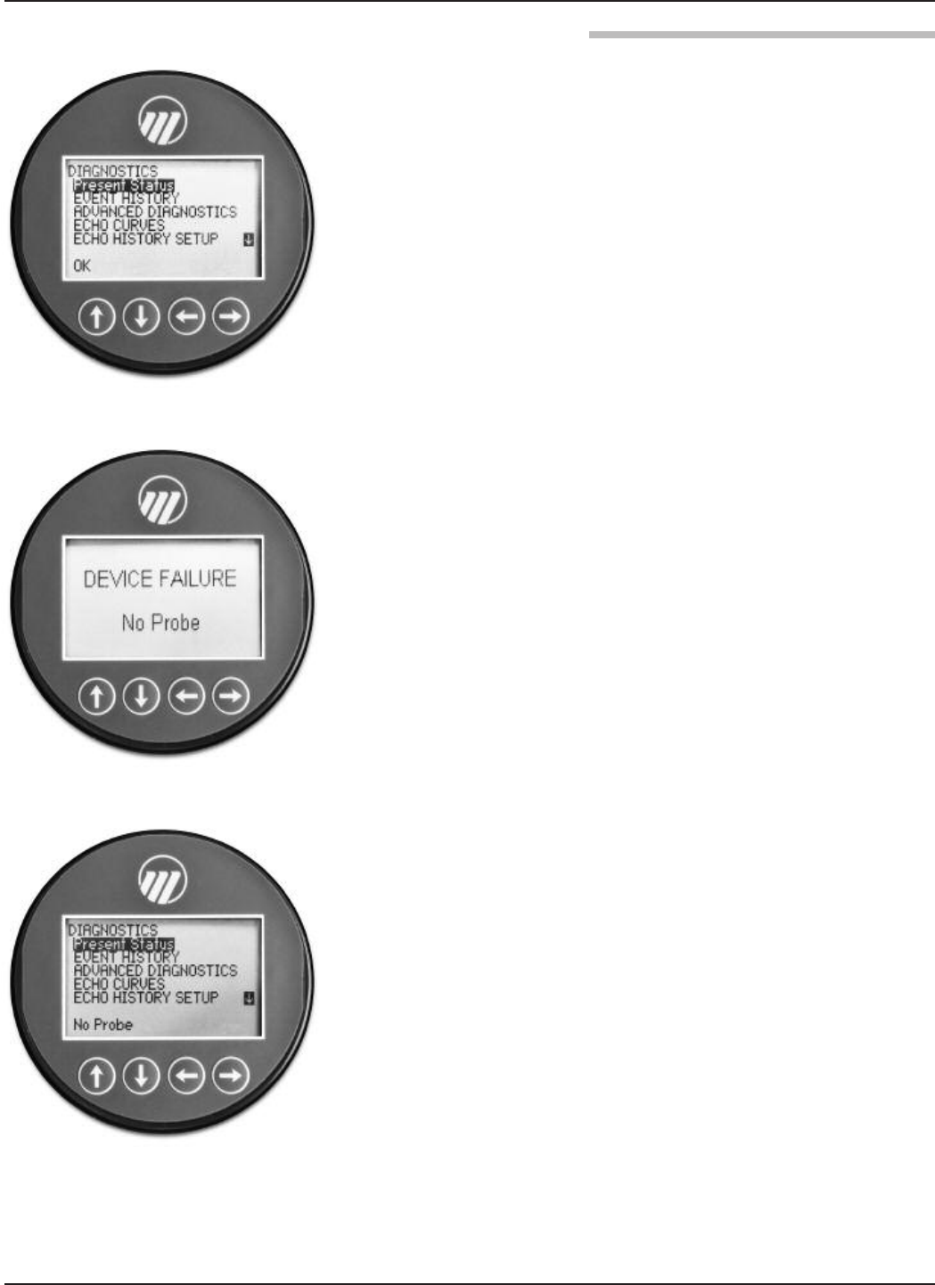
42 58-602 Pulsar® Model R96 Radar Transmitter
Selecting DIAGNOSTICS from the MAIN MENU
presents a list of five ITEMS from the top level of the
DIAGNOSTICS tree.
When Present Status is highlighted, the highest
MAGNETROL priority active diagnostic indicator (numer-
ically lowest in Table 3.3.3) is displayed on the bottom
LCD line, which is “OK” as shown at left. Pressing the
ENTER key moves the active diagnostic indicator to the
top line outdented and presents in the lower area of the
LCD a brief explanation of and possible remedies for the
indicated condition. A blank line separates the explanation
from the remedies. Additional active diagnostic indicators,
if any, appear with their explanations in descending priority
order. Each additional active indicator name-explanation
pair is separated by a blank line from the one above.
If the explanation and remedy text (and additional name-
explanation pairs) exceeds the available space, a appears
in the rightmost column of the last line indicating more text
below. In this situation, the DN key scrolls text up one line
at a time. Similarly, while text exists above the upper line of
the text field, a appears in the rightmost column of the
top (text) line. In this situation, the UP key scrolls the text
down one line at a time. Otherwise the DN and UP keys
are inoperative. In all cases the ENT or DEL key reverts to
the previous screen.
When the transmitter is operating normally and the high-
light cursor is positioned on Present Status, the bottom
LCD line displays “OK” because no diagnostic indicators
are active.
EVENT HISTORY – This menu displays the parameters
related to diagnostic event logging.
ADVANCED DIAGNOSTICS – This menu displays
parameters related to some of the advanced diagnostics
available within the Model R96.
INTERNAL VALUES – Displays read-only internal
parameters.
ELEC TEMPERATURES – Displays temperature
information as measured in the potted module in
degrees F or C.
TRANSMITTER TESTS – Allows the user to
manually set the output current to a constant value.
This is a method for the user to verify operation of the
other equipment in the loop.
ECHO CURVES – This menu allows the user to display
the live Echo Curve on the LCD.
➪
➪
FPO

43
58-602 Pulsar® Model R96 Radar Transmitter
ECHO HISTORY SETUP – The Model R96 contains the
unique and powerful feature that allows waveforms to be
automatically captured based on Diagnostic Events, Time or
both. This menu contains those parameters that configure
that feature.
Eleven (11) waveforms can be saved directly into the trans-
mitter.
• Nine (9) Troubleshooting Curves
• One (1) Echo Rejection Curve
• One (1) Reference Curve
TREND DATA – A 15-minute trend of the PV can be
displayed on the LCD.
Level reading drops out at a
repeatable position in the
vessel
Multipath signals may be
cancelling good level signal
Orient launcher to reduce multipath; turn launcher 20–30 degrees at a time until
multipath at this point disappears. Refer to Section 2.4.2.3
Level reading locked onto a
value that is not correct
Level
Measurement engine finding
a reflection it believes is
level signal
1. Is high dielectric (ε>20) foam present
2. Run False Target Rejection routine with Level below this point (or with Empty
tank) to eliminate false echoes
LEVEL, % Output and LOOP
values are all inaccurate
Basic configuration data
questionable
1. Check validity of all configuration data
2. Check DISTANCE value of device against manually measured distance
LEVEL readings are repeat-
able but consistently high (or
low) from actual by a fixed
amount
Configuration data does not
accurately match tank
dimensions
1. Ensure proper values for Tank Height and Bottom Blocking Distance
2. Check vessel for present liquid level. Trim Level can be used to ensure
exact measurement
3. Reconfigure LOOP values if necessary
LEVEL reading on Display is
correct but LOOP is stuck at
4 mA
HART Poll Address set a
value of 1-15
Set HART Poll Address to 0
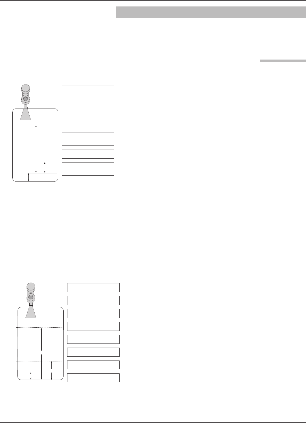
44 58-602 Pulsar®Model R96 Radar Transmitter
3.4 Configuration Information
This section is intended to offer additional configuration-
related details with respect to some of the parameters shown
in the Menu in Section 2.6.
The parameter referred to as Bottom Blocking Distance in
the PULSAR Model R96 DEVICE SETUP/BASIC
CONFIG menu is defined as the desired level reading when
liquid surface.
The PULSAR Model R96 transmitter is shipped from the
factory with Bottom Blocking Distance set to 0. With this
configuration, all measurements are referenced from the
bottom of the tank. See Example 1.
Example 1 (Bottom Blocking Distance = 0 as shipped
from factory):
Application calls for a Model R96 Antenna in an 82-inch
tank with an flanged process connection. The process
medium is water with the bottom of the probe 10 inches
above the bottom of the tank.
The user wants the 4 mA Set Point (LRV) at 24 inches
and the 20 mA Set Point (URV) at 60 inches as
referenced from the bottom of the tank.
In those applications in which it is desired to reference all
measurements from the bottom of the vessel, the value of
Level Offset should be changed to the distance between the
bottom of the probe and the bottom of the vessel as shown
in Example 2.
Example 2:
Application calls for a Model R96 Antenna in an 82-inch
tank with an flanged process connection. The process
medium is water with the bottom of the probe 10 inches
above the bottom of the tank.
The user wants the 4 mA Set Point (LRV) at 24 inches
and the 20 mA Set Point (URV) at 60 inches as
referenced from the bottom of the tank.
When the PULSAR Model R96 transmitter is mounted in a
stillwell, it is usually desirable to configure the unit with the
4 mA Set Point (LRV) at the lower process connection and
the 20 mA Set Point (URV) at the upper process connec-
tion. The measuring range then becomes the center-to-cen-
ter dimension. In this case, a negative Bottom Blocking
Distance needs to be entered. In doing so, all measurements
are then referenced at a point up on the probe, as shown in
Example 3.
10"
60"
20 mA
4 mA
24"
Level Units = inches
Antenna Model = RA6
Antenna Mount = Flange
Tank Height = 82 in
Level Offset = 0 in
Dielectric Range =
Above 10
4 mA = 24 in
20 mA = 60 in
10"
60"
20 mA
4 mA
24"
Level Units = inches
Antenna Model = RA6
Antenna Mount = Flange
Tank Height = 82 in
Level Offset = 10 in
Dielectric Range =
Above 10
4 mA = 24 in
20 mA = 60 in
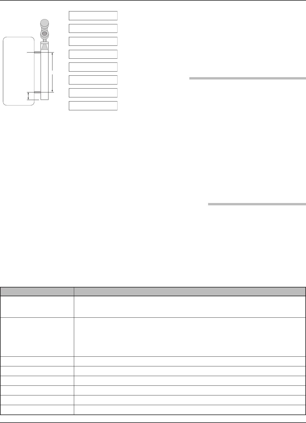
45
58-602 Pulsar®Model R96 Radar Transmitter
Example 3:
Application calls for a Model RA3 antenna flanged probe
measuring water in a 3-inch chamber with the bottom of
the probe extending 6 inches below the lower process
connection. The user wants the 4 mA point to
be 0 inches at the bottom process connection and the
20 mA point to be 30 inches at the top process connection.
Since all Non-Contact radar transmitters are
application/installation dependent, Echo Rejection (ignor-
ing false targets) is necessary.
The Model R96 transmitter Echo Rejection feature is
located in the DEVICE SETUP/ADVANCED CONFIG
menu, and requires an Advanced Password to activate. It is
highly recommended that this feature be used with the
waveform capture capability of the Model R96 DTM and
PACTware™.
Refer to Section 4 “Advanced Configuration/
Troubleshooting Techniques” or contact MAGNETROL
Technical Support for additional instructions.
Selecting Measurement Type = Volume and Level allows the
Model R96 transmitter to measure volume as the Primary
Measured Value.
3.4.3.1 Configuration using built-in Vessel Types
The following table provides an explanation of each of the
System Configuration parameters required for volume
applications that use one of the nine Vessel Types.
6"
30"
4 mA
20 mA
Level Units = inches
Probe Model = RA3
Probe Mount = Flange
Tank Height = 48 in
Level Offset =-6.0 in
Dielectric Range =
Above 10
4 mA = 0in
20 mA = 30 in
A selection of Gallons (factory default Volume Unit), Milliliters, Liters, Cubic Feet, or Cubic
Inches, is provided.
Select either Vertical/Flat (factory default Vessel Type), Vertical/Elliptical, Vertical/Spherical,
Vertical/Conical, Rectangular, Horizontal/Flat, Horizontal/Elliptical, Horizontal/Spherical,
Spherical, or Custom Table.
Note: Vessel Dims is the next screen only if a specific Vessel Type was selected. If Custom Table
was selected. Refer to page 61 to select the Cust Table Type and Cust Table Vals.
See the vessel drawings on the following page for relevant measuring areas.
Used for all Vessel Types with the exception of Rectangular.
Used for Horizontal and Vertical/Elliptical vessels.
Used for Vertical/Conical vessels.
Used for Rectangular vessels.
Used for Rectangular and Horizontal vessels.
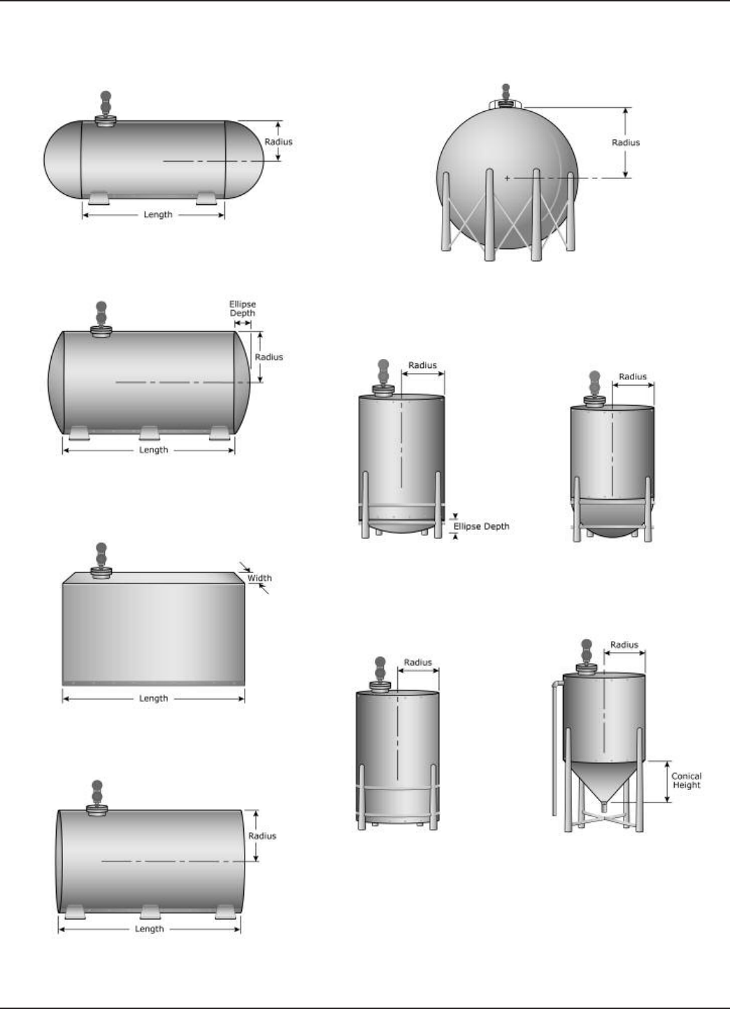
46 58-602 Pulsar®Model R96 Radar Transmitter
Vessel Types
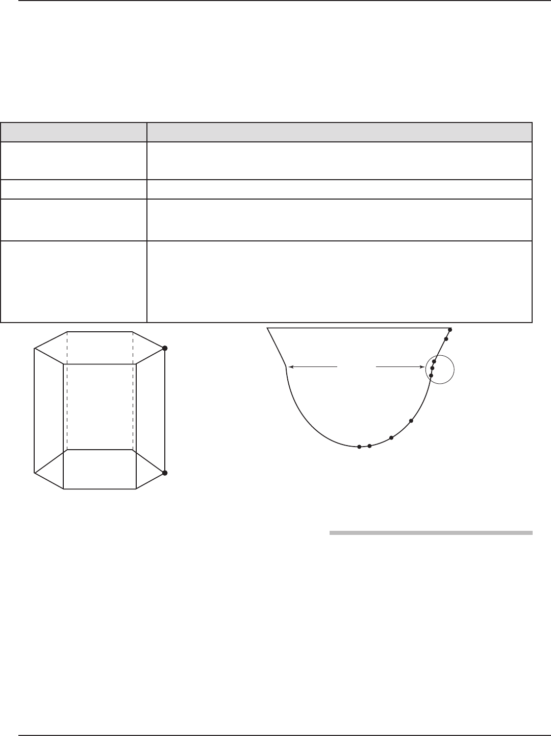
47
58-602 Pulsar®Model R96 Radar Transmitter
3.4.3.2 Configuration using Custom Table
If none of the nine Vessel Types shown can be used, a
Custom Table can be created. A maximum of 30 points can
be used to establish the level to volume relationship. The
following table provides an explanation of each of the
System Configuration parameters for volume applications
where a Custom Table is needed.
Volume Units A selection of (factory default Volume Unit), , ,
, or , is provided.
Vessel Type Select if none of the nine Vessel Types can be used.
Cust Table Type
The Custom Table points can be a (straight line between adjacent points) or
(can be a curved line between points) relationship. See below drawing for
more information.
Cust Table Vals
A maximum of 30 points can be used in building the Custom Table. Each pair of
values will have a level (height) in the units chosen in the Level Units screen, and
the associated volume for that level point. The values must be monotonic, i.e.
each pair of values must be greater than the previous level/volume pair. The last
pair of values should have the highest level value and volume value associated
with the level in the vessel.
P2
P1
P1 P2
P3
P4
P5
P6
P7
P8
P9
Transition
point
A parameter labeled “Reset Parameter” is located at the end
of the DEVICE SETUP/ADVANCED CONFIG menu.
In the event a user gets confused during configuration or
advanced troubleshooting, this parameter gives the user the
ability to reset the Model R96 transmitter configuration.
Unique to the Model R96 transmitter is the ability for
MAGNETROL to fully “pre-configure” devices to customer
requests. For that reason, the Reset function will return the
device back to the state at which it left the factory.
It is recommended that MAGNETROL Technical Support
be contacted as the Advanced User password will be
required for this reset.

48 58-602 Pulsar® Model R96 Radar Transmitter
3.5 Agency Approvals
These units are in compliance with the EMC-directive 2004/108/EC, and the ATEX directive 94/9/EC.
Explosion Proof
US/Canada:
Class I, Div 1, Group B, C, D, T6
Class I, Zone 1 AEx d IIC T6
Class I, Zone 1 Ex d IIC T6
Ta = -40ºC to +70ºC
Type 4X, IP67
Flame Proof
ATEX – FM14ATEXXXXXX:
II 2/1 G Ex d/ia IIB + H2 T6 to T1 Gb/Ga
Ta = -40ºC to +70ºC
IP67
IEC- IECEx FMG XXXX:
Ex d/ia IIB + H2 T6 to T1 Gb/Ga
Ta = -40ºC to +70ºC
IP67
Non- Incendive
US/Canada:
Class I, II, III, Division 2, Group A, B, C, D, E, F, G, T6
Class 1, Zone 2 AEx nA ia IIC T6 Gc
Class 1, Zone 2 Ex nA ia IIC T6 Gc
Ta = -40ºC to +70ºC
Type 4X, IP67
ATEX FM14ATEXXXXXX:
II 1/3 G Ex nA ia IIC T6 Gc
Ta = -15ºC to +70ºC
IP67
IEC – IECEx FMG XXXXXX:
Ex nA ia IIC T6 Gc
Ta = -15ºC to + 70ºC
IP67
Intrinsically Safe
US/Canada:
Class I, II, III, Div 1, Group A, B, C, D, E, F, G, T6,
Class I, Zone 0 AEx ia IIC T6 Ga
Class I, Zone 0 Ex ia IIC T6 Ga
Ta =-40ºC to + 70ºC
Type 4X, IP67
ATEX – FM14ATEXXXXXX:
II 1 G Ex ia IIC T4 Ga
Ta = -40ºC to +70ºC
IP67
IEC – IECEx FMG XXXXXX:
Ex ia IIC T6 Ga
Ta = -40ºC to +70ºC
IP67
Dust Ignition Proof
US/Canada:
Class II, III, Division 1, Group E, F and G, T6
Ta = -40ºC to +70ºC
Type 4X, IP67
ATEX – FM14ATEXXXXXX:
II 1/2 D Ex ia/tb IIIC T85ºC to T450ºC Da/Db
Ta = -15ºC to +70ºC
IP67
IEC – IECEx FMG XXXXXX:
Ex ia tb IIIC T85ºC to T450ºC Db
Ex ia IIIC T85ºC to T450ºC Da
Ta = -15ºC to +70ºC
IP67
The following approval standards are applicable:
FM3600:2011, FM3610:2010, FM3611:2004, FM3615:2006, FM3616:2011, FM3810:2005, ANSI/ISA60079-0:2013,
ANSI/ISA 60079-1:2009, ANSI/ISA 60079-11:2013, ANSI/ISA 60079-15:2012, ANSI/ISA 60079-26:2011, NEMA 250:2003,
ANSI/IEC 60529:2004, C22.2 No. 0.4:2009, C22.2 No. 0.5:2008, C22.2 No. 30:2007, C22.2 No. 94:2001, C22.2 No. 157:2012, C22.2 No.
213:2012, C22.2 No. 1010.1:2009, CAN/CSA 60079-0:2011, CAN/CSA 60079-1:2011, CAN/CSA 60079-11:2011, CAN/CSA 60079-15:2012,
C22.2 No. 60529:2005, EN60079-0:2012, EN60079-1:2007, EN60079-11:2012, EN60079-15:2010, EN60079-26:2007, EN60079-31:2009,
EN60529+A1:1991-2000, IEC60079-0:2011, IEC60079-1:2007, IEC60079-11:2011, IEC60079-15:2010, IEC60079-26:2006, IEC60079-31:2008
“This equipment with chargeable non-conductive parts, e.g. enclosure’s paint and antenna use PTFE, Co-polymer Polypropylene or Noryl
En265, is provided with a warning label referring to the safety measures that must be taken if there is electrostatic charging during operation.
For use in hazardous area, the equipment and side to be installed, e.g. tank, must be connected to earth and be attention to not only the meas-
uring object, e.g. liquids, gases, powders and etc., but also the related conditions, e.g. tank container, vessel and etc. (According to IEC 60079-
32-1).”
FCC Compliance Statement:
This device complies with Part 15 of the FCC Rules. Operation is subject to the following two conditions:
1. This device may not cause in harmful interference, and
2. This device must accept any interference received, including interference that may cause undesired operation.
Changes or modifications not expressly appproved by the party responsible for compliance could void the user’s authority to operate the equip-
ment. To comply with FCC/IC RF exposure limits for general population/uncontrolled exposure, the antenna(s) used for this transmitter must be
installed to provide a separation distance of at least 20cm from all persons and must not be co-located or operating in conjunction with any
other antenna or transmitter.
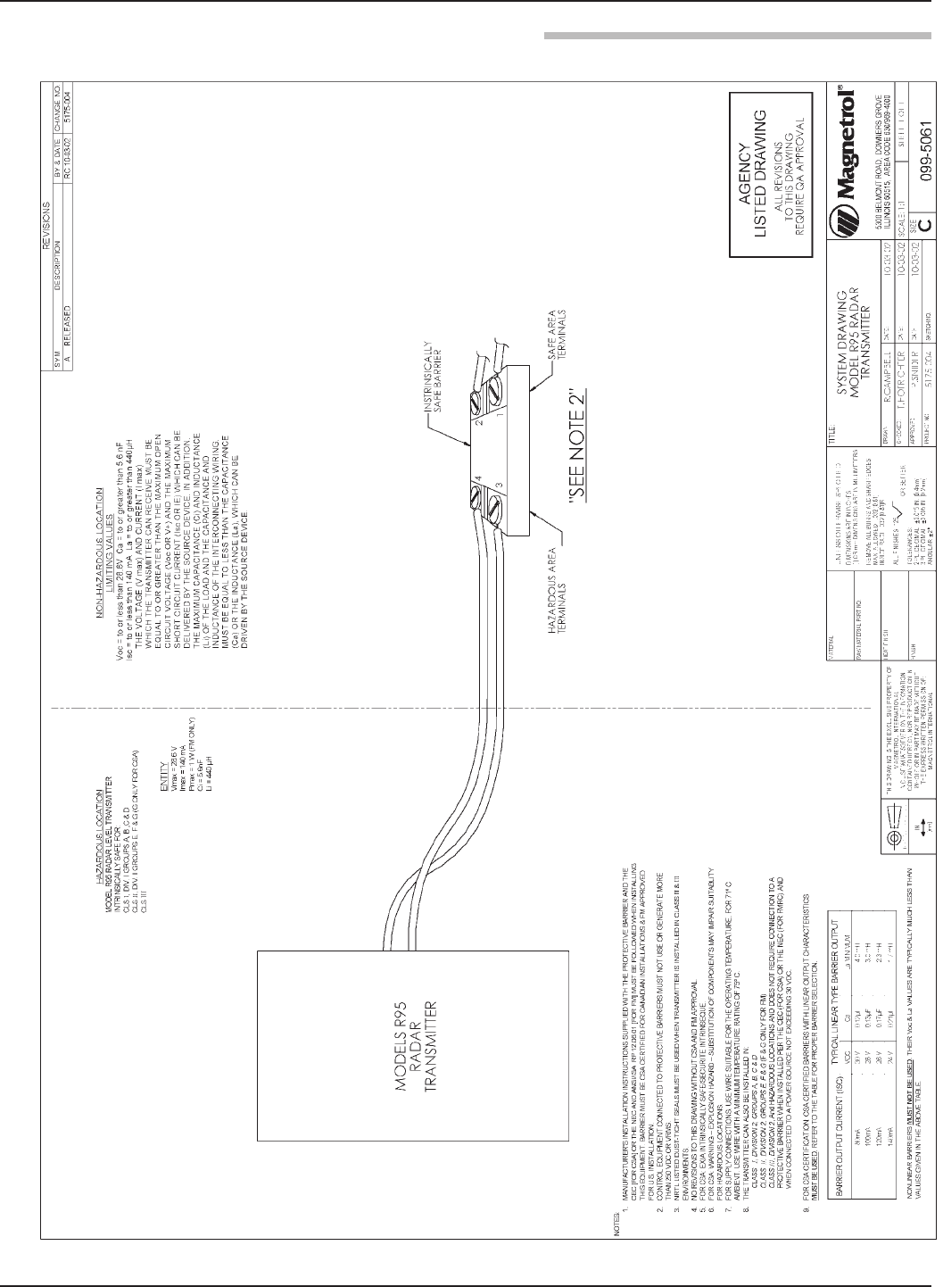
49
58-602 Pulsar® Model R96 Radar Transmitter
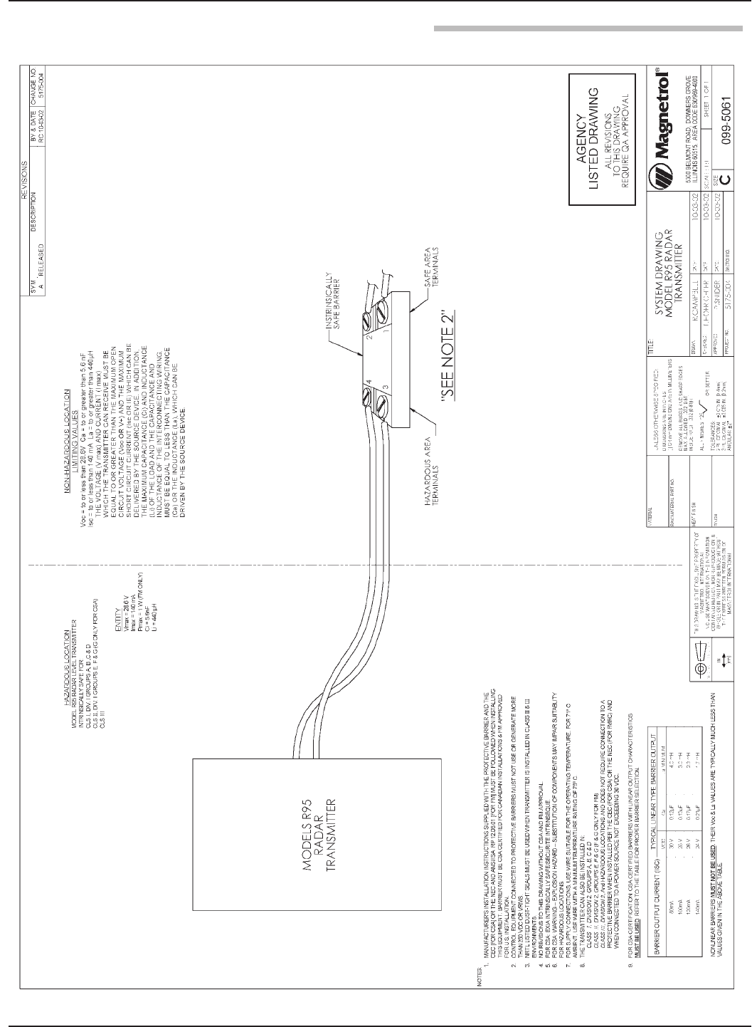
50 58-602 Pulsar®Model R96 Radar Transmitter
FF Drawing
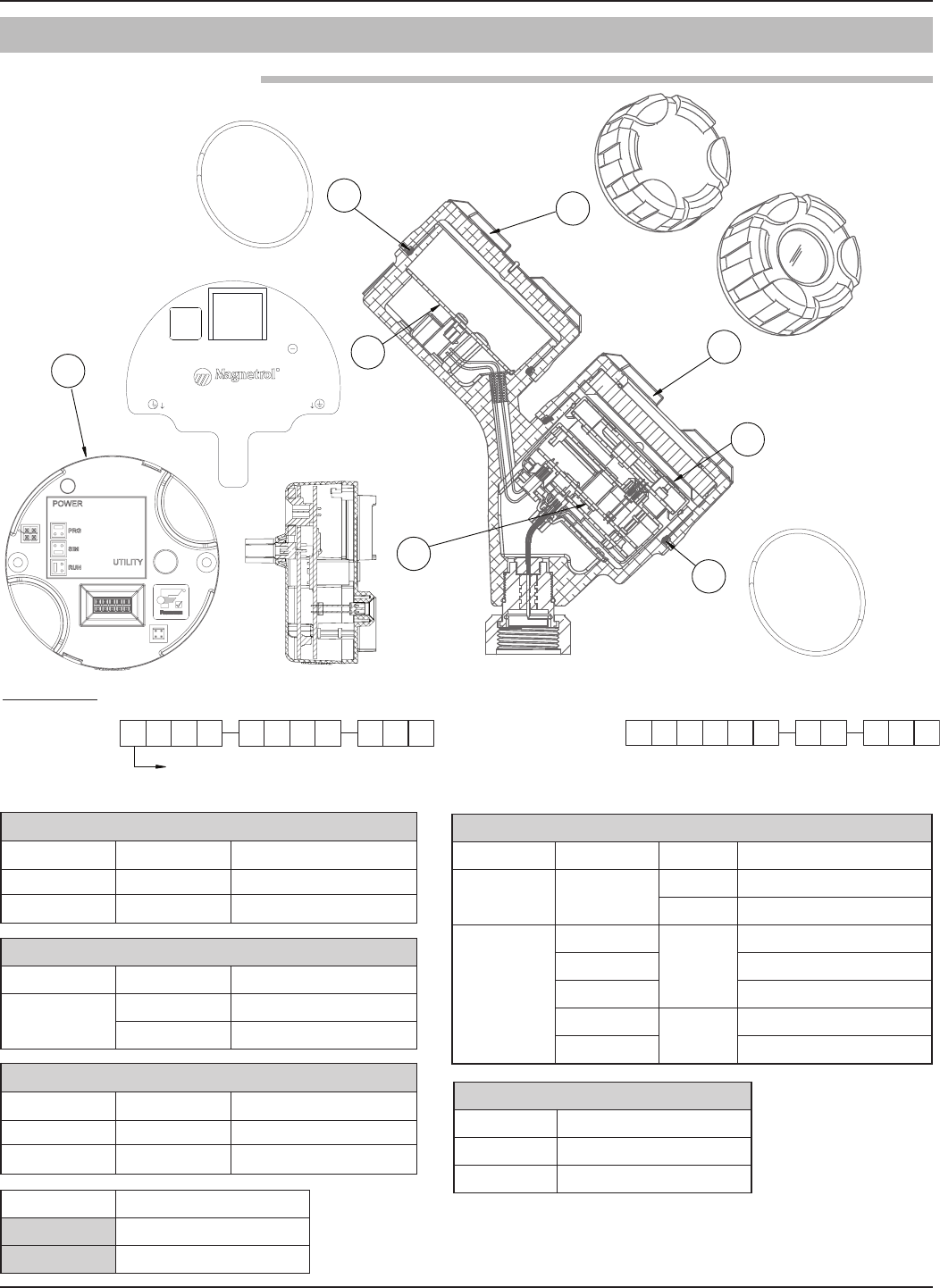
51
58-602 Pulsar®Model R96 Radar Transmitter
(1) Electronic Module
Digit 5 Digit 6 Replacement Part
1 1 Z31-2890-001
2 0 Z31-2890-002
(2) Display Module
Digit 5 Digit 7 Replacement Part
1 or 2 0, 1 or 2 N/A
A, B or C Z31-2850-001
(3) Wiring PC Board
Digit 5 Digit 6 Replacement Part
1 1 Z30-9165-001
2 0 Z30-9166-001
Replacement Part
(4) “O”-ring 012-2201-237
(5) “O”-ring 012-2201-237
(6) Housing Cover
Digit 7 Digit 8 Digit 9 Replacement Part
0, 1 or 2 all 1 004-9225-002
2 004-9225-003
A, B or C
0, 1 or A
1
036-4413-005
3 036-4413-001
B, C or D 036-4413-001
0, 1, 3 or A 2036-4413-002
B, C or D 036-4413-002
(7) Housing Cover
Digit 9 Replacement Part
1 004-9225-002
2 004-9225-003
6
7
5
2
4
1
3
RR
J1
+-
CURRENT LOOP
TB1
R
7 0 67 7 7 7 7 7 7 7
R
X = product with a non-standard customer requirement See nameplate, always provide complete part number and
serial number when ordering spares.
965
Digit:
Serial Number:
Part Number:
Electronics:
123 456 89107
1
3.6 Parts

52 58-602 Pulsar®Model R96 Radar Transmitter
3.7 Specifications
Measurement Principle Pulse burst radar 6 GHz
Measured Variable Level, determined by the time-of-flight of radar pulse reflections
Span0.5 to 130 feet (0.2 to 40 meters)
Type 4 to 20 mA with HART: 3.8 mA to 20.5 mA useable (per NAMUR NE43)
FOUNDATIONfieldbus™: H1 (ITK Ver. 6.1.1)
Range Analog .003 mA
Digital Display1 mm
Resolution Analog 0.01 mA
Digital 0.1"
Loop Resistance591 ohms @ 24 VDC and 22 mA
Diagnostic Alarm Selectable: 3.6 mA, 22 mA(meets requirements of NAMUR NE 43), or HOLD last output
Diagnostic Indication Meets requirements of NAMUR NE107
DampingAdjustable 0-10
Keypad 4-button menu-driven data entry
DisplayGraphic Liquid Crystal Display
Digital Communication ➀HART Version 7–with Field Communicator, FOUNDATIONfieldbus™, AMS, or FDT
DTM (PACTware™), EDDL
Menu LanguagesTransmitter LCD: English, French, German, Spanish, Russian
HART DD: English, French, German, Spanish, Russian, Chinese, Portuguese
FOUNDATIONfieldbus Host System: English
Measured at instrument terminals) HART: General Purpose (Weather proof)/Intrinsically Safe/Explosion-proof:
11 VDC minimum under certain conditions (refer to I/O Manual 58-602)
FOUNDATIONfieldbus™: 9 to 17.5 VDC
FISCO FNICO, Explosion Proof, General Purpose and Weather Proof
MaterialIP67/die cast aluminum A413 (<0.6% copper); optional stainless steel
Net/Gross Weight Aluminum: 4.5 lbs. (2.0 kg)
Stainless Steel: 10.0 lbs. (4.50 kg)
Overall Dimensions H 8.34" (212 mm) x W 4.03" (102 mm) x D 7.56" (192 mm)
Cable Entry 1⁄2" NPT or M20
SIL 2 Hardware(Safety Integrity Level)Safe Failure Fraction = 93% (HART only)
Functional Safety to SIL 2 as 1oo1 in accordance with IEC 61508
(Full FMEDA report available upon request)

53
58-602 Pulsar®Model R96 Radar Transmitter
Operating Temperature-40° to +175° F (-40° to +80° C); LCD viewable -5° to +160° F (-20° to +70° C)
Storage Temperature-50° to +185° F (-45° to +85° C)
Humidity0–99%, non-condensing
Electromagnetic CompatibilityMeets CE requirement (EN 61326) and NAMUR NE 21
NOTE: Antennas must be used in metallic vessel or stillwell to maintain
CE noise immunity
Surge Protection Meets CE EN 61326 (1000V)
Shock/VibrationANSI/ISA-S71.03 Class SA1 (Shock); ANSI/ISA-S71.03 Class VC2 (Vibration)
Reference ConditionsReflection from ideal reflector at +70° F (+20° C)
Linearity ±0.3 inch (8 mm) or 0.1% of tank height (whichever is greater)
Measured Error ±0.3 inch (8 mm) or 0.1% of tank height (whichever is greater)
(Performance will degrade slightly within 60" (1.5 m) of antenna)
Resolution 0.05 inch (1.2 mm)
Repeatability ±0.2 inch (5 mm) or 0.05% of tank height (whichever is greater)
Response Time(##’s 0-10 m ##’s 10-20 m #’s 20-30 m)
Initialization Time< 30 seconds
Ambient Temperature EffectTemperature effect 0.05% per 10° C
Process Dielectric Effect< 0.3 inch within selected range
Maximum Rate of Change 180 inches (450 cm)/minute
FOUNDATION™fieldbus:
ITK Version 6.1.1
H1 Device Class Link Master (LAS)— selectable ON/OFF
H1 Profile Class 31PS, 32L
Function Blocks (6) Al, (2) Transducer, (1) Resource, (1) Arithmetic, (1) Signal Characterizer,
(2) PID, (1) Integrator
Quiescent Current 15 mA
Execution Time15 ms (40 ms PID Block)
Device Revision 01
DD Version0x01
3.7 Specifications
Viton®GFLT 0 +400° F @ 232 psig
(+200° C @ 16 bar)
750 psig @ +70° F
(50 bar @ +20° C)
-40° F
(-40° C)
General purpose, steam,
ethylene
Ketones (MEK, acetone),
skydrol fluids, amines, anhydrous
ammonia, low molecular weight
esters and ethers, hot hydrofluoric
or chlorosulfuric acids, sour HCs
EPDM 1 +250° F @ 200 psig
(+125° C @ 14 bar)
750 psig @ +70° F
(50 bar @ +20° C)
-60° F
(-50° C)
Acetone, MEK, skydrol fluids
anhydrous ammonia
Petroleum oils, di-ester base
lubricants, propane, steam
Simriz SZ485
(formerly
Aegis PF128)
8+400° F @ 232 psig
+(200° C @ 16 bar)
750 psig @ +70° F
(50 bar @ +20° C)
-4° F
(-20° C)
Inorganic and organic acids
(including HF and nitric),
aldehydes, ethylene, glycols,
organic oils, silicone oils,
vinegar, sour HCs, steam,
amines, ethylene oxide,
propylene oxide
Black liquor, Freon 43, Freon 75,
Galden, KEL-F liquid, molten
sodium, molten potassium
Kalrez (4079) 2 +400° F @ 232 psig
+(200° C @ 16 bar)
750 psig @ +70° F
(50 bar @ +20° C)
-40° F
(-40° C)
Inorganic and organic acids
(including HF and nitric),
aldehydes, ethylene, glycols,
organic oils, silicone oils,
vinegar, sour HCs
Black liquor, hot water/steam, hot
aliphatic amines, ethylene oxide,
propylene oxide, molten sodium,
molten potassium
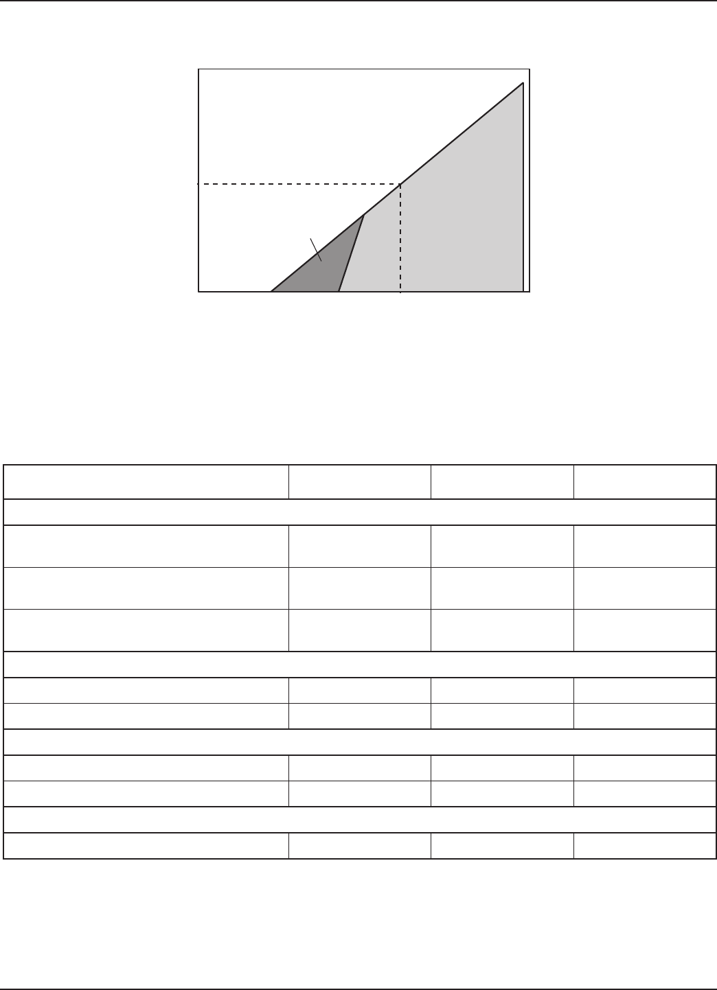
54 58-602 Pulsar® Model R96 Radar Transmitter
Operational Mode Current Consumption Vmin Vmax
HART
General Purpose 4mA
20mA
16.25V
11V
36V
36V
Intrinsically Safe 4mA
20mA
16.25V
11V
28.6V
28.6V
Explosion Proof 4mA
20mA
16.25V
11V
36V
36V
Fixed Current-Solar Power Operation (PV transmitter via HART)
General Purpose 10mA➀11V 36V
Intrinsically Safe 10mA➀11V 28.6V
HART Multi-Drop Mode (Fixed Current)
Standard 4mA➀16.25V 36V
Intrinsically Safe 4mA➀16.25V 28.6V
(Future)
Supply Voltage 9V to 17.5V 9V to 17.5V 9V to 17.5V
3.7.2.2 Transmitter Terminal Voltage
3.7.2.1 Safe Operating Area
0
Vsupply
Typical HART
4-20 mA
Operating Area
Digital Solar Mode
Safe Operating Area
16.25 V
591
Ω
24 V 36 V
Loop
R
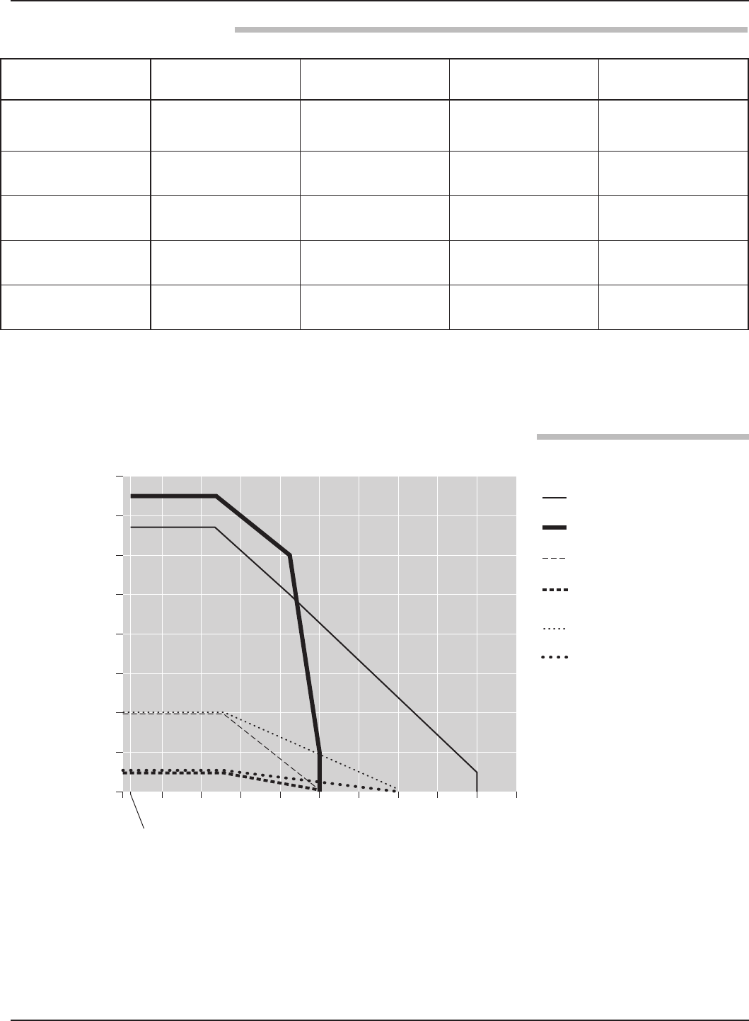
55
58-602 Pulsar® Model R96 Radar Transmitter
-50
(-46)
-40
(-40)
0
(-18)
0
100 (7)
200 (14)
300 (21)
400 (28)
500 (34)
600 (41)
700 (48)
800 (55)
50
(10)
100
(38)
150
(66)
200
(93)
250
(121)
300
(149)
350
(177)
400
(204)
450
(232)
Temperature ° F (° C)
Pressure psig (bar)
Polypropylene Rod
PTFE Rod & Horn
All-Polypropylene Flanged
All-Polypropylene Threaded and
Flanged ASME B31.1 & B31.3
All-Halar Threaded and
Flanged ASME B31.1 & B31.3
All-Halar Flanged
➀ All-polypropylene construction optional (see chart below for ratings)
➀
➀
316 SS (Hastelloy®C, Monel®
and Kynar®optional), TFE,
Viton®O-rings
316 SS, Polypropylene,
Viton®O-rings All-Halar, Viton®O-rings
316 SS (Hastelloy C
and Monel optional), TFE,
Viton®O-rings
11⁄2" NPT and BSP, ANSI or DIN
flanges
11⁄2" NPT and BSP, ANSI or DIN
flanges
11⁄2” NPT, BSP, ANSI, or DIN
Flanges 6" ANSI or DIN flanges
+400° F @ 50 psig
(+204° C @ 3.5 bar)
+200° F @ 50 psig
(+93° C @ 3.5 bar)
+300° F @ atmos
(+150° C @ atmos)
+400° F @ 50 psig
(+204° C @ 3.5 bar)
-14.7 to 675 psig @ +70° F
(-1.0 to 46.5 bar @ +20° C)
-14.7 to 750 psig @ +70° F
(-1.0 to 51.7 bar @ +20° C)
-14.7 to 50 psig @ +70° F
(-1.0 to 3.5 bar @ +20° C)
-14.7 to 675 psig @ +70° F
(-1.0 to 46.5 bar @ +20° C)
2.0 2.0 2.0 1.4 with stillwells
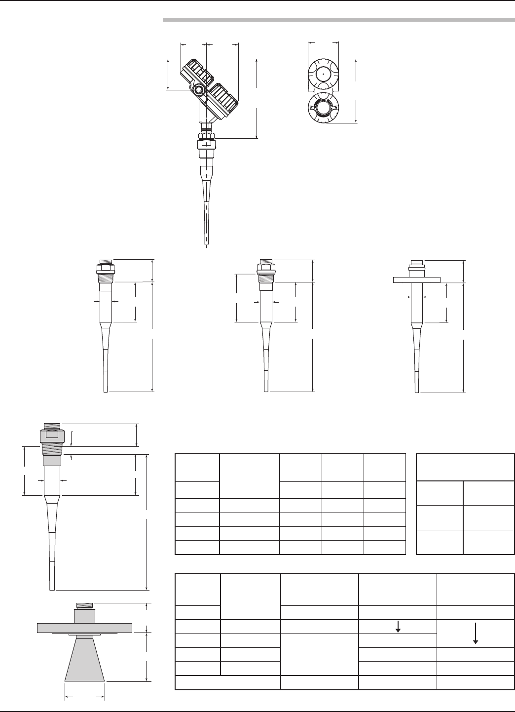
56 58-602 Pulsar® Model R96 Radar Transmitter
ANSI and DIN Flanges
3 (76)
B
A
D∅
NPT
3 (76)
B
A
D⌀
BSP
3 (76)
B
A
CD⌀
10.21
(259)
3.98
(101)
3.34
(85)
4.05
(103)
8.41
(214)
4.02
(102)
2.3 (58) 11.1 (282) 3.0 (76)
5.1 (130) 14.0 (356) 5.9 (150)
9.1 (231) 18.0 (457) 9.9 (251)
13.1 (333) 22.0 (559) 13.9 (353)
∅ 1.625 (41)
∅1.50 (38)
∅ 1.625 (41)
2.8
(55)
0.68 (17) Thread
Engagement
A
C
B
D∅
3
(76)
H
∅
Aperture
2.7 (51)
N/A
4.6 (117)
8.4 (213) 8.3 (211)
12.4 (315) 12.4 (315)
2.95" (75 mm) 3.75" (95 mm) 5.75" (146 mm)
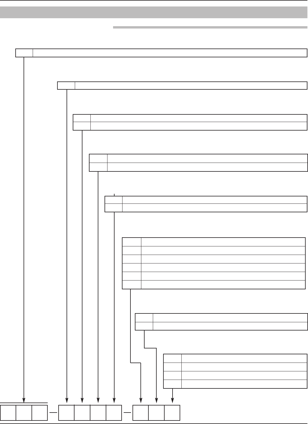
57
58-602 Pulsar® Model R96 Radar Transmitter
3.8 Model Numbers
1 4–20 mA with HART
2F
OUNDATION fieldbus
R96 Through-Air Radar Level Transmitter- 6 GHz Pulse Radar
1 |
5|
0 No Digital Display and Keypad
A Digital Display and Keypad
7|
5 24 VDC, Two-wire
4|
9|
8|
6|SAFETY OPTIONS
0 None (FOUNDATION fieldbus only) (5th digit = 2)
1 SIL 2 Hardware - HART only (5th digit = 1)
1 Die-cast Aluminum, Dual-compartment, 45-degree
2 Investment Cast, Stainless Steel, Dual-compartment, 45-degree
10 |CONDUIT CONNECTION
01⁄2" NPT
1 M20
21⁄2" NPT with sunshade
3 M20 with sunshade
0 General Purpose, Weatherproof (IP 67)
1Intrinsically Safe (FM & CSA CL 1 Div 1, Grps A, B, C, D) (5th digit = 1 or 2)
3Explosion-proof (FM & CSA CL 1 Div 1, Grps B, C, D)
AIntrinsically Safe (ATEX/IEC Ex ia IIC T4) (5th digit = 1 or 2)
BFlame-proof (ATEX/IEC Ex d ia IIC T6) (5th digit = 1 or 2)
CNon-sparking (ATEX Ex n IIC T6) (5th digit = 1 or 2)
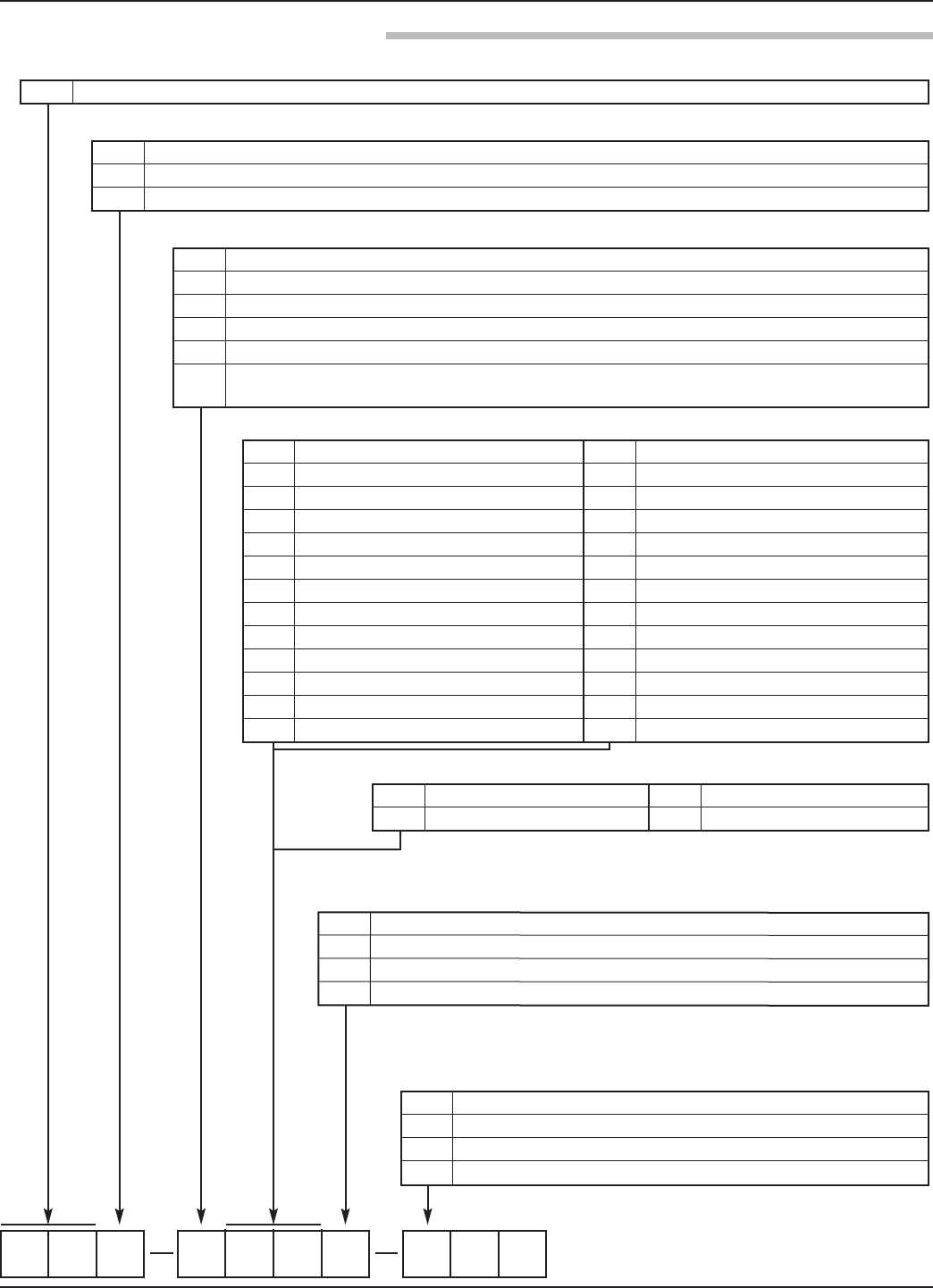
58 58-602 Pulsar® Model R96 Radar Transmitter
31 11⁄2" NPT thread 32 11⁄2" BSP (G 11⁄2) thread
43 2" 150# ANSI raised face flange DA DN 50, PN 16 DIN 2527 Form B
44 2" 300# ANSI raised face flange DB DN 50, PN 25/40 DIN 2527 Form B
45 2" 600# ANSI raised face flange DD DN 50, PN 64 DIN 2527 Form E
53 3" 150# ANSI raised face flange EA DN 80, PN 16 DIN 2527 Form B
54 3" 300# ANSI raised face flange EB DN 80, PN 25/40 DIN 2527 Form B
55 3" 600# ANSI raised face flange ED DN 80, PN 64 DIN 2527 Form E
63 4" 150# ANSI raised face flange FA DN 100, PN 16 DIN 2527 Form B
64 4" 300# ANSI raised face flange FB DN 100, PN 25/40 DIN 2527 Form B
65 4" 600# ANSI raised face flange FD DN 100, PN 64 DIN 2527 Form E
73 6" 150# ANSI raised face flange GA DN 150, PN 16 DIN 2527 Form B
74 6" 300# ANSI raised face flange GB DN 150, PN 25/40 DIN 2527 Form B
75 6" 600# ANSI raised face flange GD DN 150, PN 64 DIN 2527 Form E
R A PULSAR radar antennas / 6 GHz
ATFE (Material of Construction codes A, B, C, and K only)
B Polypropylene (Material of Construction codes A, G, K, and L only)
C Halar®(Material of Construction codes G and L only)
A 316/316L stainless steel
BHastelloy®C
C Monel®
G All-Plastic wetted surfaces including flanges (Configuration/Style codes B and C only)
K 316/316L SS; ASME B31.1 and B31.3 (meets CRN specifications)
LAll-Plastic wetted surfaces; ASME B31.1, B31.3
(meets CRN specifications; Configuration/Style codes B and C only)
0Viton®GFLT
1EPDM
2Kalrez 4079
8Simriz SZ485 (formerly Aegis PF128)
➁
0 For nozzle height ≤ 1" (25 mm) (For threaded process connection only)
1 For nozzle height ≤ 4" (100 mm)
2 For nozzle height ≤ 8" (200 mm) (ESP designation for TFE rod only)
3 For nozzle height ≤ 12" (300 mm)
➀
➀Metal flanges welded to antenna; Plastic flanges and metal flanges with
threaded antenna connection ordered separately. Refer to Optional Flanges
chart on page 59.
➁All-Polypropylene and All-Halar antennas (Materials of Construction Codes G and L)
use Viton®GFLT O-rings
4P 2" Triclover®type, 16 AMP 6P 4" Triclover type, 16 AMP
5P 3" Triclover type, 16 AMP 7P 6" Triclover type, 16 AMP
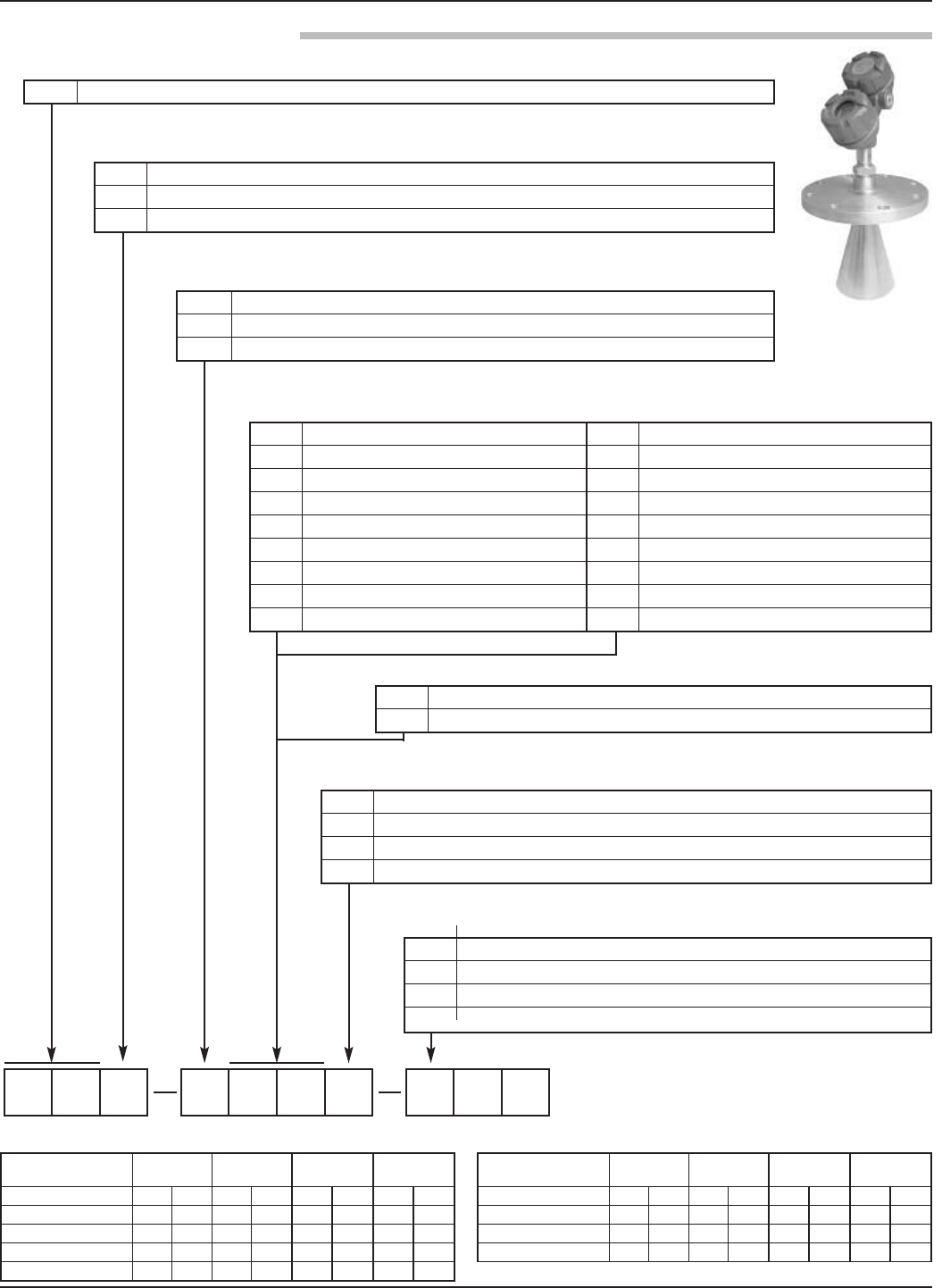
59
58-602 Pulsar® Model R96 Radar Transmitter
R A PULSAR radar antennas / 6 GHz
3 3" horn (for Standpipe/Stillwell use only; Materials of Construction codes A & K only
4 4" horn
6 6" horn
A 316/316L stainless steel
B Hastelloy C
K 316/316L SS; ASME B31.1 and ASME B31.3 (meets CRN specifications)
0 Viton®GFLT
1 EPDM
2 Kalrez®4079
8 Simriz SZ485 (formerly Aegis PF128)
6P 4" Tri-Clover type, 16 AMP Hygienic Flange
7P 6" Tri-Clover type, 16 AMP Hygienic Flange
Part Number:
04-6852
2"
150# 300#
3"
150# 300#
4"
150# 300#
6"
150# 300#
316L Stainless Steel -001 -005 -002 -006 -003 -007 -004 -008
304L Stainless Steel -009 -013 -010 -014 -011 -015 -012 -016
Carbon Steel -017 -021 -018 -022 -019 -023 -020 -024
Hastelloy C -025 -029 -026 -030 -027 -031 -028 -032
Monel -033 -037 -034 -038 -035 -039 -036 -040
Part Number:
04-6852
2"
150# 300#
3"
150# 300#
4"
150# 300#
6"
150# 300#
Kynar -041 -045 -042 -046 -043 -047 -044 -048
PVC -049 -053 -050 -054 -051 -055 -052 -056
Polypropylene -057 -061 -058 -062 -059 -063 -060 -064
TFE -065 -069 -066 -070 -067 -071 -068 -072
0 For nozzle height ≤ 1" (25 mm) (For threaded process connection only)
1 For nozzle height ≤ 4" (100 mm)
2 For nozzle height ≤ 8" (200 mm) (ESP designation for TFE rod only)
3 For nozzle height ≤ 12" (300 mm)
53 3" 150# ANSI raised face flange EA DN 80, PN 16 DIN 2527 Form B
54 3" 300# ANSI raised face flange EB DN 80, PN 25/40 DIN 2527 Form B
55 3" 600# ANSI raised face flange ED DN 80, PN 64 DIN 2527 Form E
63 4" 150# ANSI raised face flange FA DN 100, PN 16 DIN 2527 Form B
64 4" 300# ANSI raised face flange FB DN 100, PN 25/40 DIN 2527 Form B
65 4" 600# ANSI raised face flange FD DN 100, PN 64 DIN 2527 Form E
73 6" 150# ANSI raised face flange GA DN 150, PN 16 DIN 2527 Form B
74 6" 300# ANSI raised face flange GB DN 150, PN 25/40 DIN 2527 Form B
75 6" 600# ANSI raised face flange GD DN 150, PN 64 DIN 2527 Form E
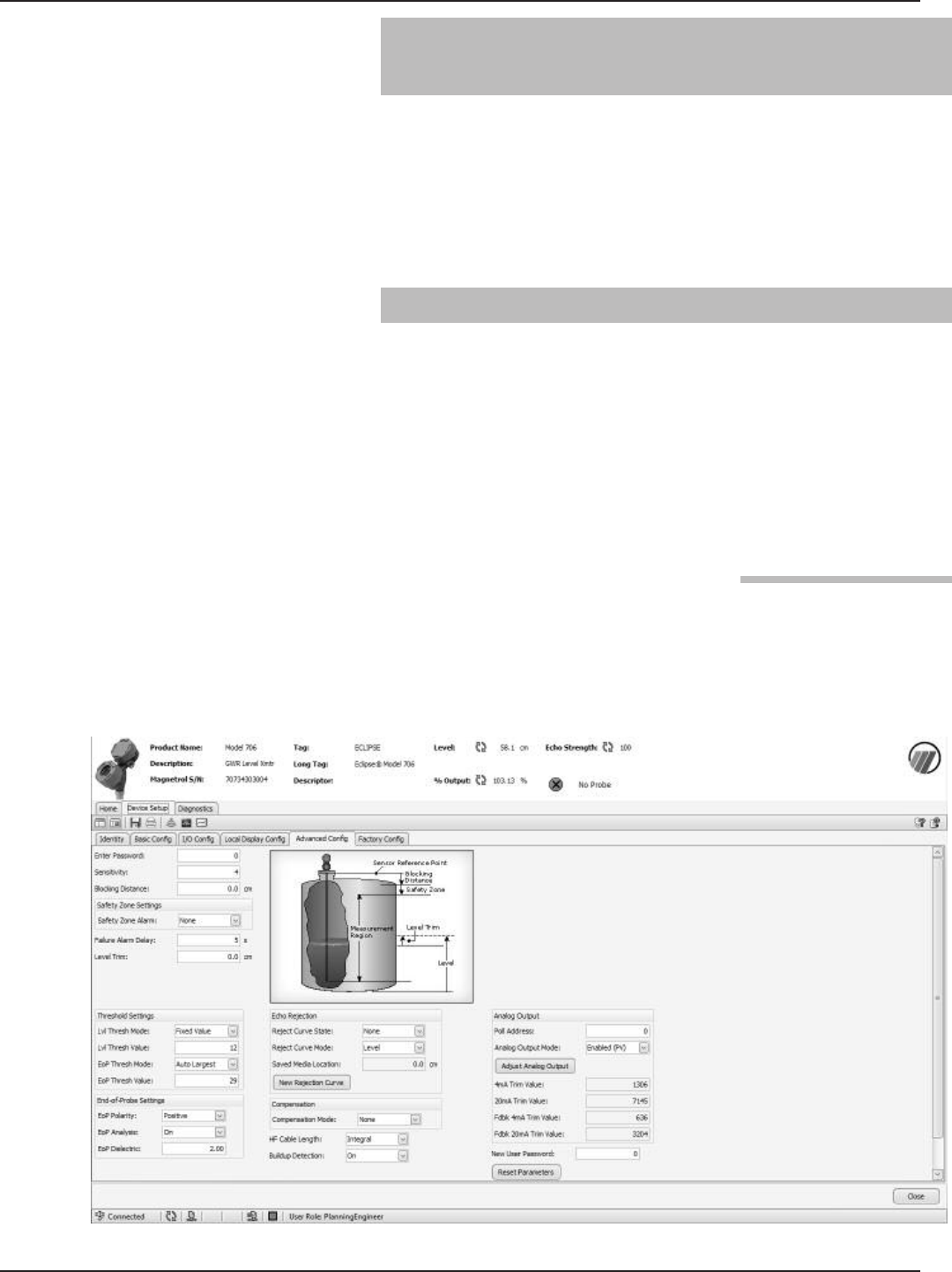
60 58-602 Pulsar® Model R96 Radar Transmitter
4.0 Advanced Configuration/
Troubleshooting Techniques
This section contains information regarding some of the
advanced configuration and troubleshooting capability con-
tained within the Model R96 transmitter. These diagnostic
options are best suited for use with PACTware and the
Model R96 DTM, and should be implemented only after
contacting Magnetrol Technical Support.
4.1 End-of-Probe Analysis (EOPA)
Please note that due to the operation of this method, End
of Probe Analysis cannot be applied with interface measure-
ment, applications with a "water" bottoms, or with stratify-
ing liquids. Therefore, EOPA will not be available when
Measurement Type = Interface & Level.
When EOPA is enabled and the calculated (inferred level) is
being used, a diagnostic warning shown as "Inferred Level”
will be present.
4.1.1 Enable EOPA using PACTware
Click on the Device Setup tab, and then select Advanced
Config. In the lower left corner select the correct Polarity
for the End of Probe pulse, then turn on the EoP Analysis.
The Eop Dielectric box will then appear. Fill in the correct
Dielectric of the process medium being measured.
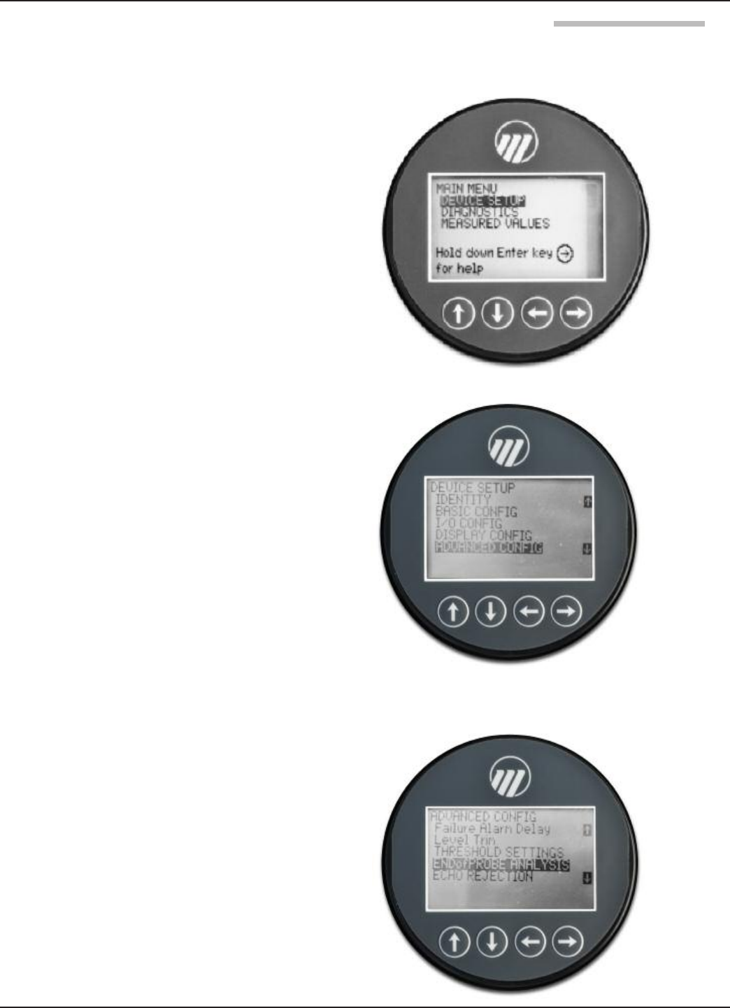
61
58-602 Pulsar® Model R96 Radar Transmitter
4.1.2 Enable EOPA using keypad/LCD
From the MAIN MENU, select DEVICE SETUP and
press Enter.
Scroll down to Advanced Config, and then press Enter.
Scroll down to END of PROBE ANALYSIS, and then press
Enter.

62 58-602 Pulsar® Model R96 Radar Transmitter
Enter the correct polarity for EoP Polarity, turn on EoP
Analysis, and then enter the correct value for EoP
Dielectric. EoP Dielectric is the dielectric constant of the
process medium being measured.
4.2 Sloped Threshold
The Sloped Threshold option contained in the Model R96
allows the user additional level detection capability by
allowing the threshold to be sloped (bent) around an
unwanted signal. The result is a convenient way to ignore
undesired signals.
The use of PACTware and the Model R96 DTM is recom-
mended for this option.
Using PACTware, click on the Device Setup tab, and then
select Advanced Config.
In the Threshold Settings section, select “Sloped” within in
the Lvl Tresh Mode dropdown box.
Then set the Sloped Start Value, Lvl Tresh Value, and
Sloped End Distance.
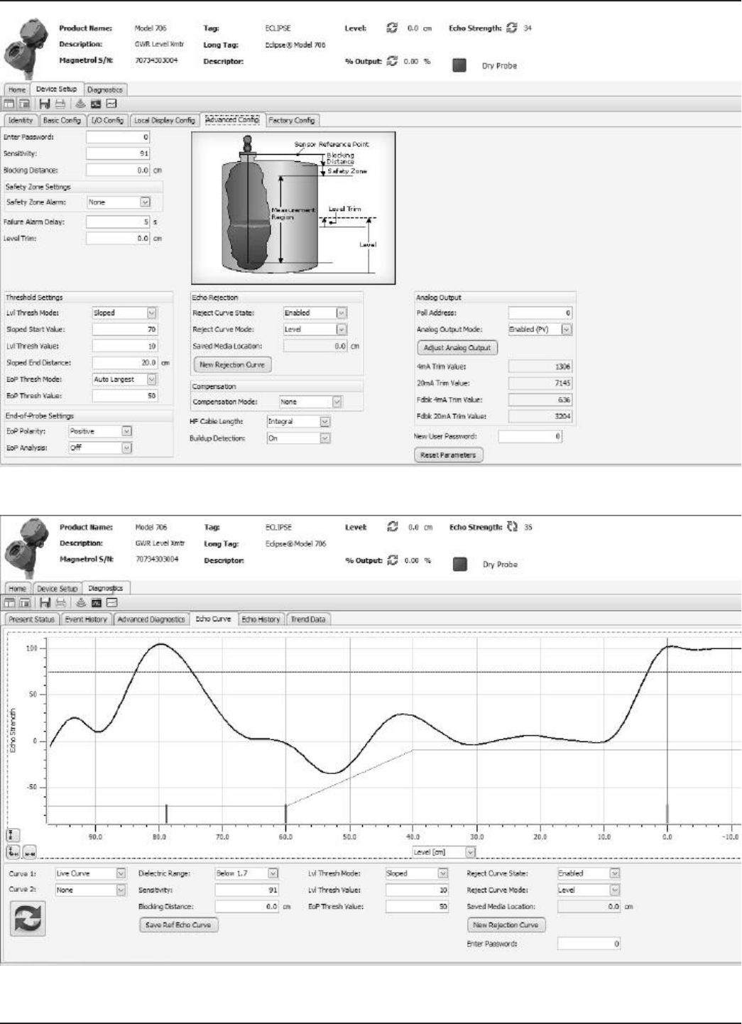
58-602 Pulsar® Model R96 Radar Transmitter
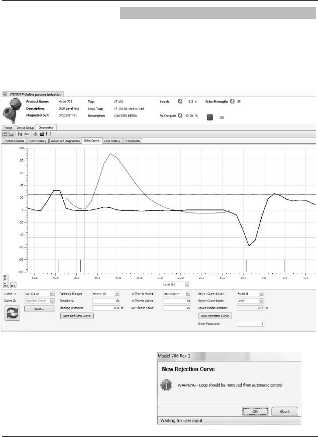
64 58-602 Pulsar® Model R96 Radar Transmitter
4.3 Echo Rejection
Another way to ignore unwanted signals along the length of
the probe is by utilizing the Echo Rejection feature.
Setup using PACTware
Select the Diagnostics tab and then the Echo Curve tab.
Then click on New Rejection Curve
Click on OK at the loop warning message.
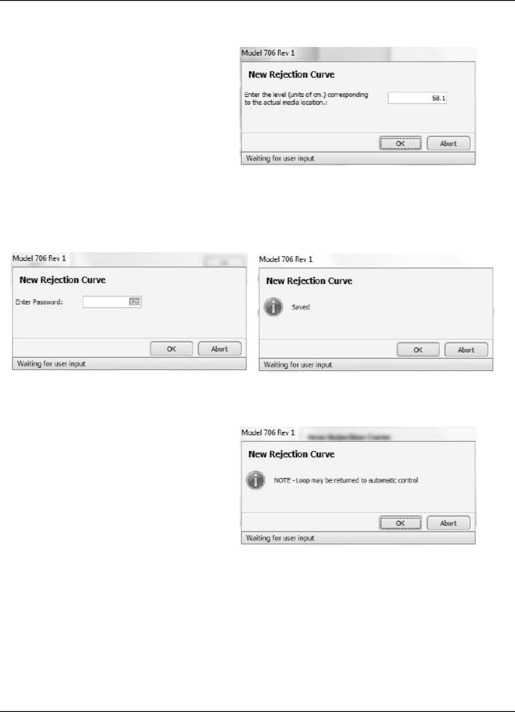
65
58-602 Pulsar® Model R96 Radar Transmitter
On the next screen, please enter the actual process media
location and then hit OK.
A password window will then appear (unless the password
was previously entered). Enter the password and hit OK.
Then the system calculates the curve, and then saves it. Hit
OK to confirm.
A warning screen is then shown so that the loop can be
returned to automatic control.
At this point the echo rejection curve can be viewed by
selecting Rejection Curve as Curve 2 in the lower left corner
of the screen. The Rejection curve will then be displayed in
red as shown in the screenshot above.
Alternatively, you can follow the procedure below:
Select the Device Setup tab, and then select the Advanced
Config tab. Then click on New Rejection Curve.
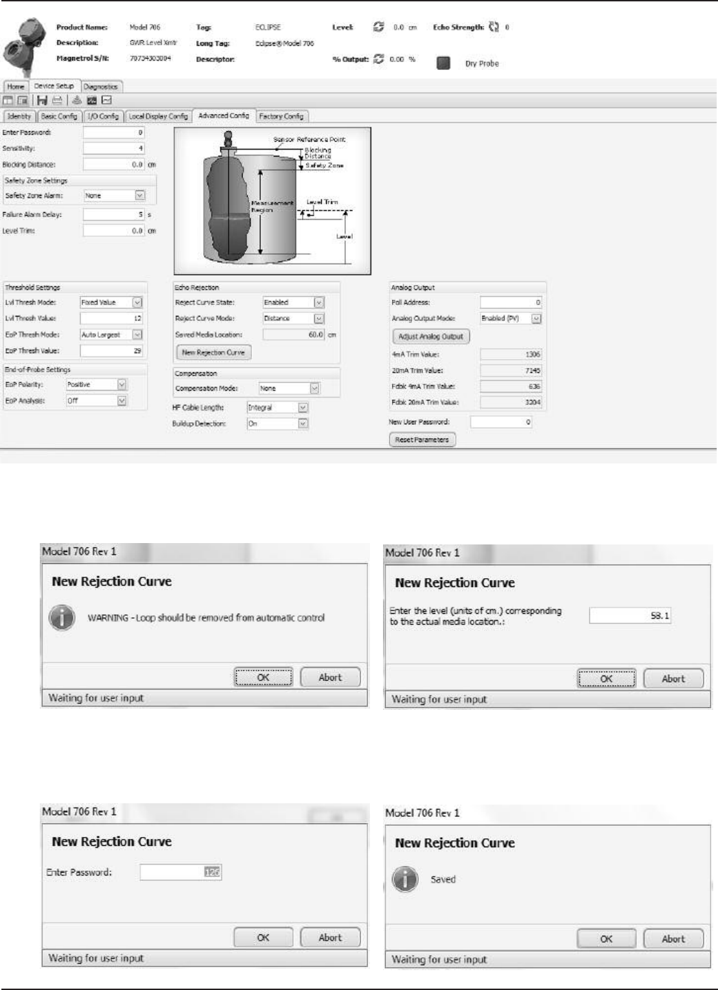
66 58-602 Pulsar® Model R96 Radar Transmitter
You will get a warning regarding the loop, hit OK. On the
next screen you need to enter the actual media location and
then hit OK.
Next a password window might appear if not already
entered. Then the system calculates the curve, and then
saves it. Hit OK to confirm.
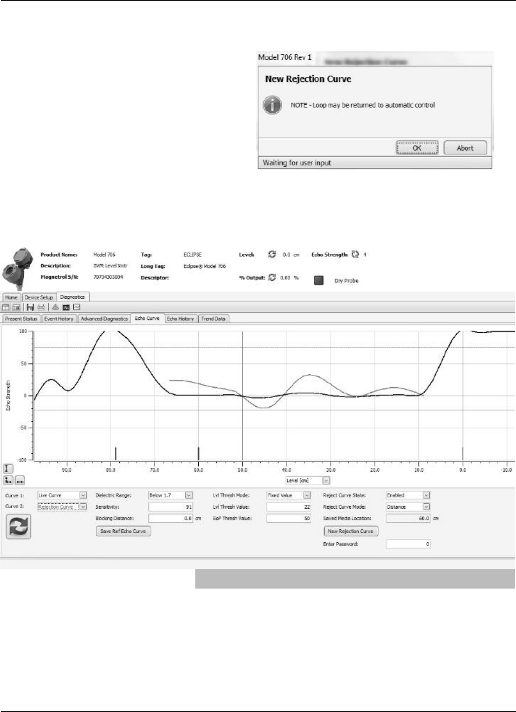
67
58-602 Pulsar® Model R96 Radar Transmitter
A warning screen is shown that the loop can be returned to
automatic control.
At this point the echo rejection curve can be viewed by
selecting Rejection Curve as Curve 2 in the lower left corner
of the Echo Curve screen. The Rejection curve will then be
displayed in red as shown in the screenshot below.
4.4 Buildup Detection
A unique feature contained within the Model R96 can be
used to obtain an indication of build-up along the length of
the probe. This can be set as the HART SV or TV which
can be monitored in the control room. An algorithm com-
pares the buildup echo strength as compared to the Lvl
Thrsh Value, and outputs value in percent.
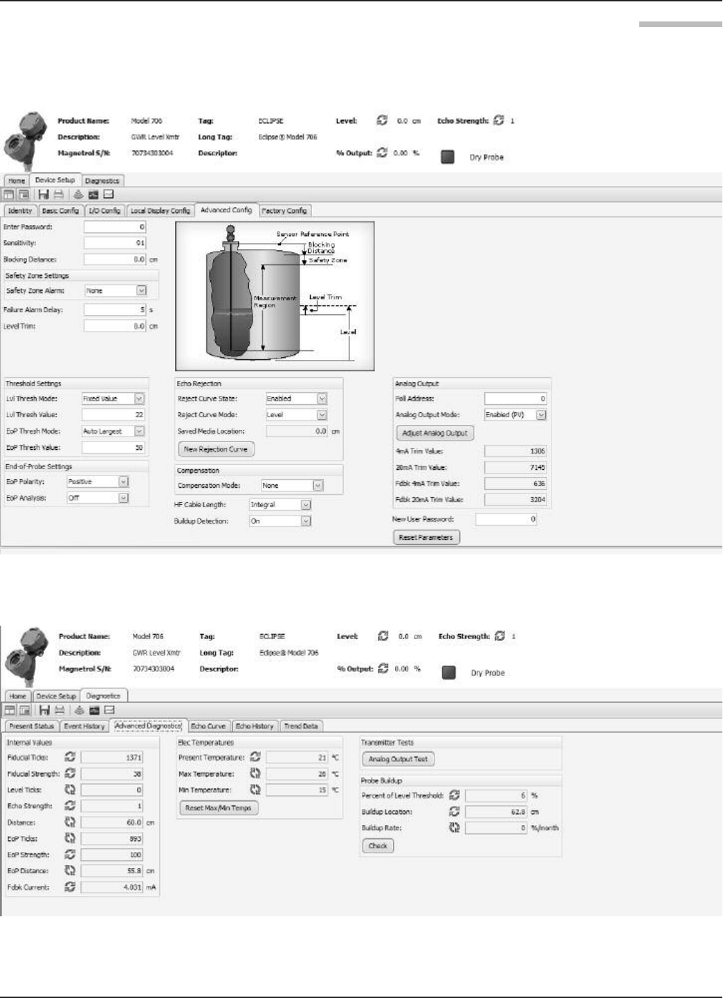
68 58-602 Pulsar® Model R96 Radar Transmitter
4.4.1 Buildup Detection Setup using PACTware
Buildup detection is a feature that needs to be turned on in
Advanced Config, see below.
Once turned on progress can be checked in the Advanced
Diagnostics screen, see below.
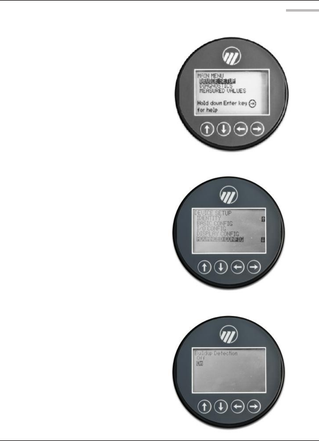
69
58-602 Pulsar® Model R96 Radar Transmitter
4.4.2 Buildup Detection Setup using the Keypad
From the menu select DEVICE SETUP and hit Enter.
Scroll down to Buildup Detection and hit Enter
Select On and hit Enter
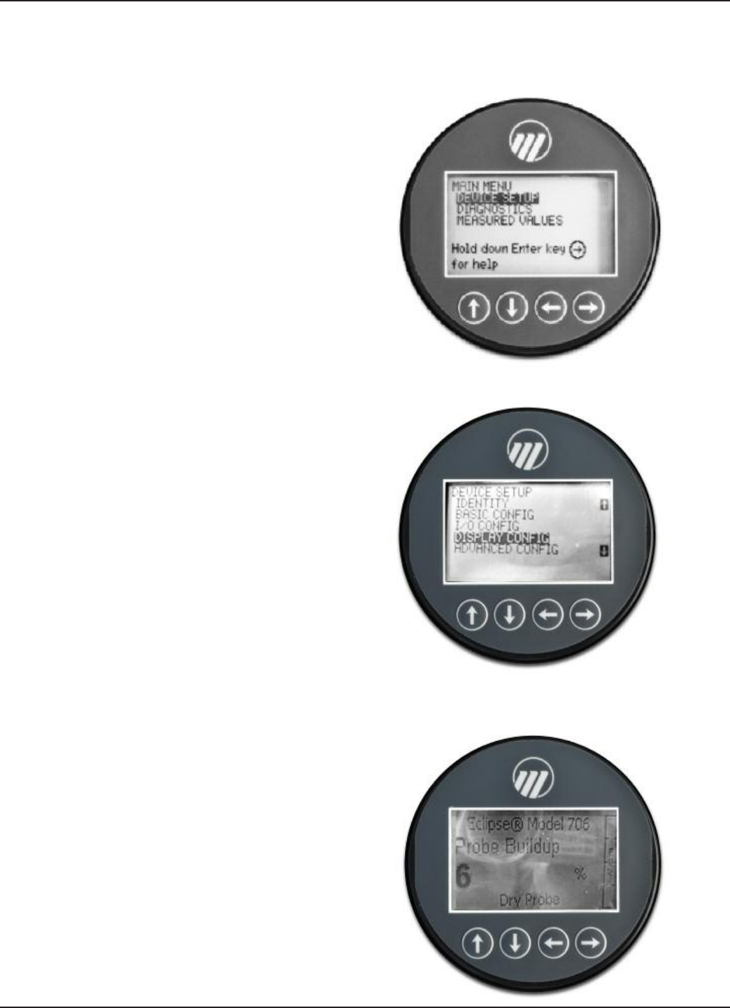
70 58-602 Pulsar® Model R96 Radar Transmitter
Checking buildup can be done from the main display
screen. First the unit must be set up to display the Buildup
percentage. Go to the main menu and select DEVICE
SETUP then hit Enter.
Scroll down to DISPLAY CONFIG and hit Enter.
Scroll down to Probe Buildup and hit Enter, then select
View. From the main screen the Buildup percentage is now
shown.

71
58-602 Pulsar® Model R96 Radar Transmitter

Service Policy
Owners of MAGNETROL may request the return of a
control or any part of a control for complete rebuilding or
replacement. They will be rebuilt or replaced promptly.
Controls returned under our service policy must be
returned by Prepaid transportation. MAGNETROL will
repair or replace the control at no cost to the purchaser
(or owner) other than transportation if:
1. Returned within the warranty period; and
2. The factory inspection finds the cause of the claim to
be covered under the warranty.
If the trouble is the result of conditions beyond our con-
trol; or, is NOT covered by the warranty, there will be
charges for labor and the parts required to rebuild or
replace the equipment.
In some cases it may be expedient to ship replacement
parts; or, in extreme cases a complete new control, to
replace the original equipment before it is returned. If this
is desired, notify the factory of both the model and serial
numbers of the control to be replaced. In such cases, cred-
it for the materials returned will be determined on the
basis of the applicability of our warranty.
No claims for misapplication, labor, direct or consequen-
tial damage will be allowed.
Return Material Procedure
So that we may efficiently process any materials that are
returned, it is essential that a “Return Material
Authorization” (RMA) number be obtained from the fac-
tory, prior to the material’s return. This is available through
a MAGNETROL local representative or by contacting the
factory. Please supply the following information:
1. Company Name
2. Description of Material
3. Serial Number
4. Reason for Return
5. Application
Any unit that was used in a process must be properly
cleaned in accordance with OSHA standards, before it is
returned to the factory.
A Material Safety Data Sheet (MSDS) must accompany
material that was used in any media.
All shipments returned to the factory must be by prepaid
transportation.
All replacements will be shipped F.O.B. factory.
Magnetrol, Magnetrol logotype and Pulsar are registered trademarks of Magnetrol International, Incorporated.
Viton® and Kalrez® are registered trademarks of DuPont Performance Elastomers.
HART® is a registered trademark of the HART Communication Foundation
PACTware™ is trademark of PACTware Consortium
CSA logotype is a registered trademark of Canadian Standards Association
Halar® is a registered trademark of Allied Chemical Corp.
Hastelloy® is a registered trademark of Haynes International, Inc.
Monel® is a registered trademark of Special Metals Corporation (Formerly Inco Alloys International)
KYNAR® is a registered trademark of Pennsalt Chemicals Corp.
Tri-Clover is a registered trademark of Tri-Clover, Inc.
705 Enterprise Street • Aurora, Illinois 60504-8149 • 630-969-4000 • Fax 630-969-9489
info@magnetrol.com • www.magnetrol.com
Copyright © 2015 Magnetrol International, Incorporated. All rights reserved. Printed in the USA.
PULSAR Pulse Burst Radar transmitters may be protected by one or more of the following U.S. Patent Nos.:
US 6,062,095; US 6,980,174; US 7,102,584; US 7,106,248; US 7,271,646