AMPAK Technology AP6212SD WLAN module User Manual rev2
AMPAK Technology Inc. WLAN module Users Manual rev2
UserManual.wiki
>
AMPAK Technology
>
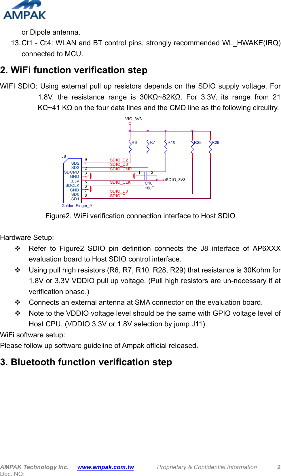
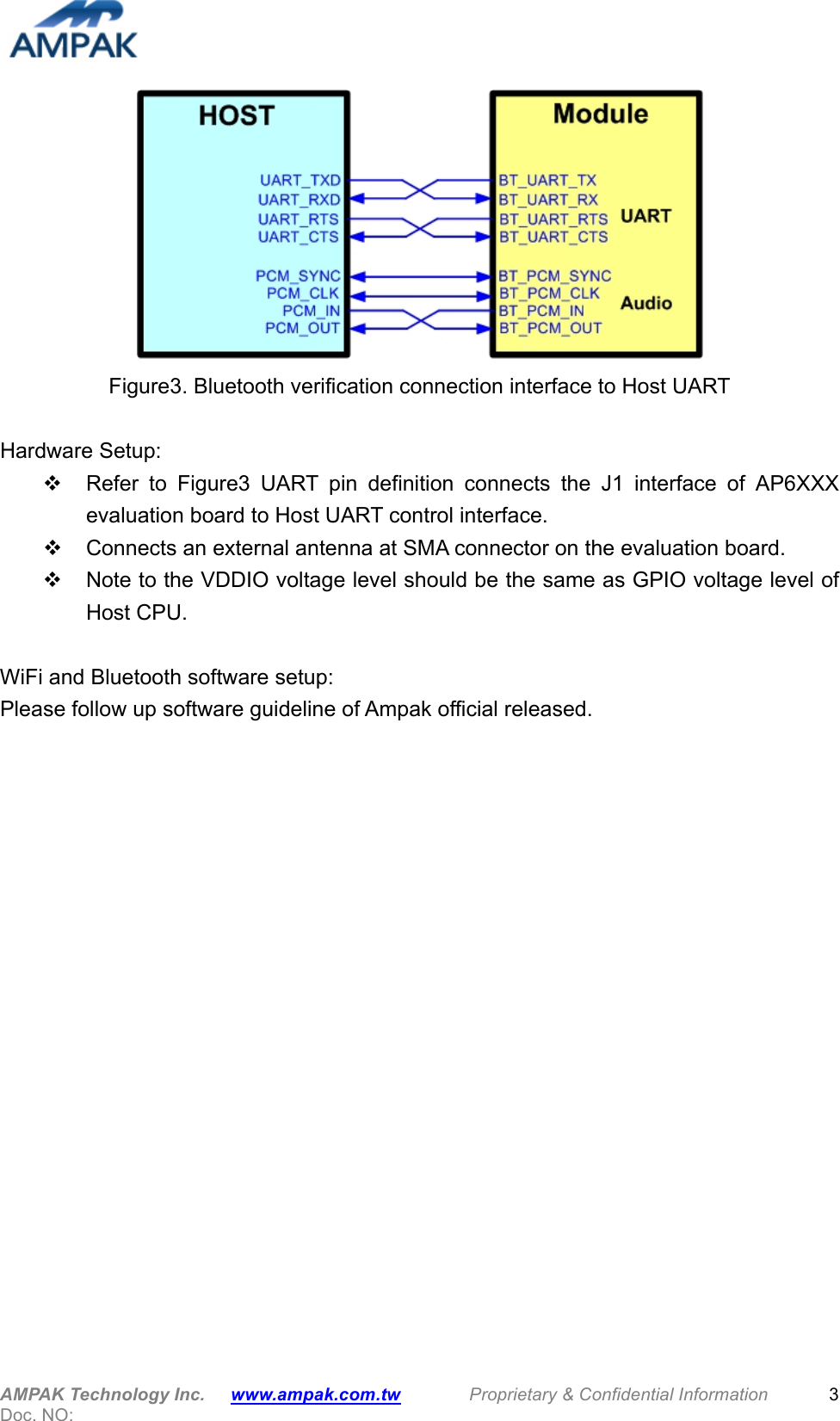
AP6212SD User Manual
Users Manual_rev2
Navigation menu
Upload a User Manual
Namespaces
Wiki Guide
HTML
PDF
Info
Views
User Manual
Discussion / Help
Navigation