AMPAK Technology AP6212SD WLAN module User Manual rev2
AMPAK Technology Inc. WLAN module Users Manual rev2
Users Manual_rev2

AMPAK Technology Inc. www.ampak.com.tw Proprietary & Confidential Information i
Doc. NO:
AMPAK
AP6212SD
Evaluation Kits
User manual
Version 1.0
Federal Communication Commission Interference Statement
This device complies with Part 15 of the FCC Rules. Operation is subject to
the following two conditions: (1) This device may not cause harmful
interference, and (2) this device must accept any interference received,
including interference that may cause undesired operation.
This equipment has been tested and found to comply with the limits for a
Class B digital device, pursuant to Part 15 of the FCC Rules. These limits
are designed to provide reasonable protection against harmful interference in a
residential installation. This equipment generates, uses and can radiate radio
frequency energy and, if not installed and used in accordance with the
instructions, may cause harmful interference to radio communications.
However, there is no guarantee that interference will not occur in a particular
installation. If this equipment does cause harmful interference to radio or
television reception, which can be determined by turning the equipment off
and on, the user is encouraged to try to correct the interference by one of the
following measures:
- Reorient or relocate the receiving antenna.
- Increase the separation between the equipment and receiver.
- Connect the equipment into an outlet on a circuit different from that
to which the receiver is connected.
- Consult the dealer or an experienced radio/TV technician for help.
FCC Caution: Any changes or modifications not expressly approved by the
party responsible for compliance could void the user's authority to operate this
equipment.
This transmitter must not be co-located or operating in conjunction with any
other antenna or transmitter.

Radiation Exposure Statement:
This equipment complies with FCC radiation exposure limits set forth for an
uncontrolled environment. This equipment should be installed and operated
with minimum distance 20cm between the radiator & your body.
This device is intended only for OEM integrators under the following conditions:
1) The transmitter module may not be co-located with any other transmitter
or antenna.
As long as 2 conditions above are met, further transmitter test will not be
required. However, the OEM integrator is still responsible for testing their
end-product for any additional compliance requirements required with this
module installed
IMPORTANT NOTE: In the event that these conditions can not be met (for
example certain laptop configurations or co-location with another transmitter),
then the FCC authorization is no longer considered valid and the FCC ID can
not be used on the final product. In these circumstances, the OEM integrator
will be responsible for re-evaluating the end product (including the transmitter)
and obtaining a separate FCC authorization.
End Product Labeling
The product can be kept as far as possible from the user body or set the device
to lower output power if such function is available. The final end product must
be labeled in a visible area with the following: “Contains FCC
ID:ZQ6-AP6212SD”. The grantee's FCC ID can be used only when all FCC
compliance requirements are met.
Manual Information To the End User
The OEM integrator has to be aware not to provide information to the end user
regarding how to install or remove this RF module in the user’s manual of the
end product which integrates this module.
The end user manual shall include all required regulatory information/warning
as show in this manual.

Industry Canada statement:
This device complies with ISED’s licence-exempt RSSs. Operation is subject to the
following two conditions: (1) This device may not cause harmful interference, and (2)
this device must accept any interference received, including interference that may
cause undesired operation.
Le présent appareil est conforme aux CNR d’ ISED applicables aux appareils radio
exempts de licence. L’exploitation est autorisée aux deux conditions suivantes : (1) le
dispositif ne doit pas produire de brouillage préjudiciable, et (2) ce dispositif doit
accepter tout brouillage reçu, y compris un brouillage susceptible de provoquer un
fonctionnement indésirable.
Radiation Exposure Statement:
This equipment complies with ISED radiation exposure limits set forth for an
uncontrolled environment. This equipment should be installed and operated with
minimum distance 20cm between the radiator & your body.
Déclaration d'exposition aux radiations:
Cet équipement est conforme aux limites d'exposition aux rayonnements ISED
établies pour un environnement non contrôlé. Cet équipement doit être installé et
utilisé avec un minimum de 20 cm de distance entre la source de rayonnement et votre
corps.
This device is intended only for OEM integrators under the following conditions: (For
module device use)
1) The antenna must be installed such that 20 cm is maintained between the antenna
and users, and
2) The transmitter module may not be co-located with any other transmitter or
antenna.
As long as 2 conditions above are met, further transmitter test will not be required.
However, the OEM integrator is still responsible for testing their end-product for any
additional compliance requirements required with this module installed.
Cet appareil est conçu uniquement pour les intégrateurs OEM dans les conditions
suivantes: (Pour utilisation de dispositif module)
1) L'antenne doit être installée de telle sorte qu'une distance de 20 cm est respectée
entre l'antenne et les utilisateurs, et
2) Le module émetteur peut ne pas être coïmplanté avec un autre émetteur ou antenne.
Tant que les 2 conditions ci-dessus sont remplies, des essais supplémentaires sur
l'émetteur ne seront pas nécessaires. Toutefois, l'intégrateur OEM est toujours
responsable des essais sur son produit final pour toutes exigences de conformité
supplémentaires requis pour ce module installé.
IMPORTANT NOTE:
In the event that these conditions can not be met (for example certain laptop
configurations or co-location with another transmitter), then the Canada authorization
is no longer considered valid and the IC ID can not be used on the final product. In
these circumstances, the OEM integrator will be responsible for re-evaluating the end
product (including the transmitter) and obtaining a separate Canada authorization.
NOTE IMPORTANTE:
Dans le cas où ces conditions ne peuvent être satisfaites (par exemple pour certaines
configurations d'ordinateur portable ou de certaines co-localisation avec un autre
émetteur), l'autorisation du Canada n'est plus considéré comme valide et l'ID IC ne
peut pas être utilisé sur le produit final. Dans ces circonstances, l'intégrateur OEM
sera chargé de réévaluer le produit final (y compris l'émetteur) et l'obtention d'une
autorisation distincte au Canada.
End Product Labeling
This transmitter module is authorized only for use in device where the antenna may be
installed such that 20 cm may be maintained between the antenna and users. The final
end product must be labeled in a visible area with the following: “Contains
IC: 11956A-AP6212SD ”.
Plaque signalétique du produit final
Ce module émetteur est autorisé uniquement pour une utilisation dans un dispositif où
l'antenne peut être installée de telle sorte qu'une distance de 20cm peut être maintenue
entre l'antenne et les utilisateurs. Le produit final doit être étiqueté dans un endroit
visible avec l'inscription suivante: "Contient des IC: 11956A-AP6212SD ".
Manual Information To the End User
The OEM integrator has to be aware not to provide information to the end user
regarding how to install or remove this RF module in the user’s manual of the end
product which integrates this module.
The end user manual shall include all required regulatory information/warning as
show in this manual.
Manuel d'information à l'utilisateur final
L'intégrateur OEM doit être conscient de ne pas fournir des informations à l'utilisateur
final quant à la façon d'installer ou de supprimer ce module RF dans le manuel de
l'utilisateur du produit final qui intègre ce module.
Le manuel de l'utilisateur final doit inclure toutes les informations réglementaires
requises et avertissements comme indiqué dans ce manuel.
DETACHABLE ANTENNA USAGE
This radio transmitter (IC: 11956A / Model: AP6212SD) has been approved by ISED
to operate with the antenna type listed below with maximum permissible gain
indicated. Antenna types not included in this list, having a gain greater than the
maximum gain indicated for that type, are strictly prohibited for use with this device.
Le présent émetteur radio (IC: 11956A / Model: AP6212SD) a été approuvé par ISED
pour fonctionner avec les types d'antenne énumérés ci-dessous et ayant un gain
admissible maximal. Les types d'antenne non inclus dans cette liste, et dont le gain est
supérieur au gain maximal indiqué, sont strictement interdits pour l'exploitation de
l'émetteur.
Approved antenna(s) list
Type
Gain
Brand
Manufacturer
PIFA
0.5dBi
INPAQ
INPAQ

第十二條 經型式認證合格之低功率射頻電機,非經許可,公司、商號或使用者均
不得擅自變更頻率、加大功率或變更原設計之特性及功能。
第十四條 低功率射頻電機之使用不得影響飛航安全及干擾合法通信;經發現有干
擾現象時,應立即停用,並改善至無干擾時方得繼續使用。
前項合法通信,指依電信法規定作業之無線電通信。
低功率射頻電機須忍受合法通信或工業、科學及醫療用電波輻射性電機設
備之干擾。
1. 本模組於取得認證後將依規定於模組本體標示審驗合格標籤。
2. 系統廠商應於平台上標示「本產品內含射頻模組:XXXyyyLPDzzzz-x」字 樣 。
AMPAK Technology Inc. www.ampak.com.tw Proprietary & Confidential Information
Doc. NO:
1
1. AP6XXX Evaluation Board Introduction
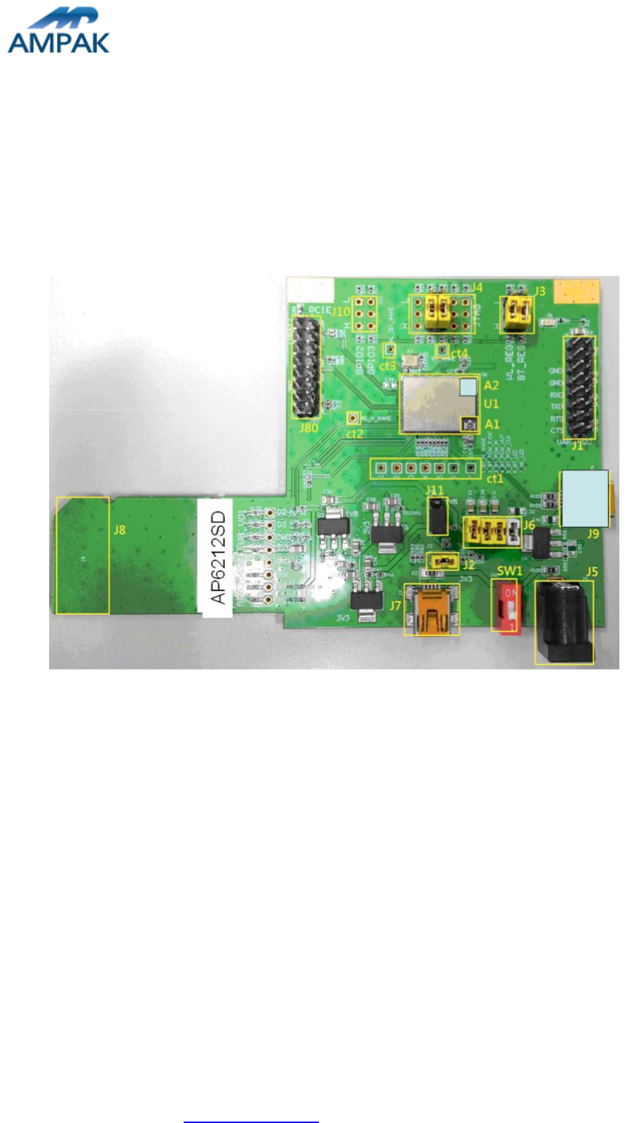
AP6212SD Evaluation board (EVB) likes as figure1. That is designed for IEEE802.11
b/g/n WLAN with integrated Bluetooth application. It is subject to provide a convenient
environment for customer’s verification on WiFi or Bluetooth function. There are many
controller pins and reserved GPIO on Evaluation board which describes as below.
Figure1. Top view of AP6212SD EVB
Interface highlights:
1. U1: AP6212SD SIP module.
2. J1: UART interface connects with UART transport board for BT.
3. J3: Enable (H) or disable (L) Bluetooth and WiFi Function.
4. J4: SDIO interface strapping option
5. J5: 5V DC adaptor input connector.
6. J6: 3V3 RF / VBAT / WL_VIO / BT_VIO for main system I/O power path.
7. J7 / J9: 5V DC mini USB input connector.
8. J8: Standard SDIO interfaces for Wi-Fi performance measured.
9. J10: GPIO_2 (input / output) and GPIO_3 (input / output)
10. J11: WL_VIO power path for 1V8 or 3V3 selection.
11. SW1: Power on/off switch.
12. A1: I-PEX connector let RF signal in / out path, you could connect with RF cable
AMPAK Technology Inc. www.ampak.com.tw Proprietary & Confidential Information
Doc. NO:
2
or Dipole antenna.
13. Ct1 - Ct4: WLAN and BT control pins, strongly recommended WL_HWAKE(IRQ)
connected to MCU.
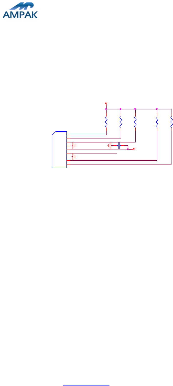
2. WiFi function verification step
WIFI SDIO: Using external pull up resistors depends on the SDIO supply voltage. For
1.8V, the resistance range is 30KΩ~82KΩ. For 3.3V, its range from 21
KΩ~41 KΩ on the four data lines and the CMD line as the following circuitry.
SDIO_D3
SDIO_D2
SDIO_D1
C10
10uF
1 2
R6 R7 R10
SDIO_D0
J8
Golden Finger_9
SD3 1
SDCMD 2
GND 3
3.3V 4
SDCLK 5
GND 6
SD0 7
SD1 8
SD2 9
SDIO_CLK
R28 R29
SDIO_CMD
VIO_3V3
SDIO_3V3
Figure2. WiFi verification connection interface to Host SDIO
Hardware Setup:
v Refer to Figure2 SDIO pin definition connects the J8 interface of AP6XXX
evaluation board to Host SDIO control interface.
v Using pull high resistors (R6, R7, R10, R28, R29) that resistance is 30Kohm for
1.8V or 3.3V VDDIO pull up voltage. (Pull high resistors are un-necessary if at
verification phase.)
v Connects an external antenna at SMA connector on the evaluation board.
v Note to the VDDIO voltage level should be the same with GPIO voltage level of
Host CPU. (VDDIO 3.3V or 1.8V selection by jump J11)
WiFi software setup:
Please follow up software guideline of Ampak official released.
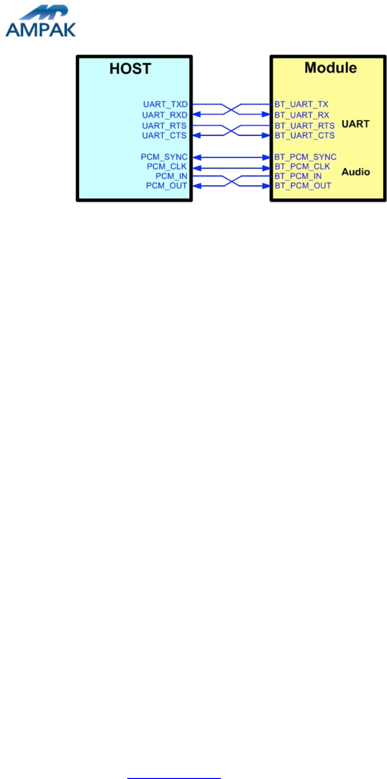
3. Bluetooth function verification step
AMPAK Technology Inc. www.ampak.com.tw Proprietary & Confidential Information
Doc. NO:
3
Figure3. Bluetooth verification connection interface to Host UART
Hardware Setup:
v Refer to Figure3 UART pin definition connects the J1 interface of AP6XXX
evaluation board to Host UART control interface.
v Connects an external antenna at SMA connector on the evaluation board.
v Note to the VDDIO voltage level should be the same as GPIO voltage level of
Host CPU.
WiFi and Bluetooth software setup:
Please follow up software guideline of Ampak official released.