Contents
- 1. User Manual ACV-2100.QSG
- 2. User Manual ACV-5100.QSG
- 3. User Manual Safety Instruction
User Manual ACV-2100.QSG
QUICK START GUIDE
ACV-2100 Acendo Vibe™ Conferencing Sound Bar
Overview
The ACV-2100 features a connector bay door that also serves as a hinged Wall Mount
Bracket, which allows easy access to the Connector Bay without having to dismount
the unit. The Wall Mount Bracket features a cutout for cable routing and straps for cable
management.
Credenza Installation
Note: To ensure highest possible sound quality, the rubber feet on the bottom panel
must remain in place for surface-mount installations.
The ACV-2100 can sit on a hard, flat surface such as a credenza, tabletop or desk.
When choosing a surface location, consider a space that will not interfere with
workspaces or other installed devices. Connect cables as necessary - see the
Connections section for details.
Wall Mount Installation
For best aesthetic in wall mount installations, remove the rubber feet from the bottom
panel: carefully peel each foot off of the bottom surface.
Removing the Wall Mount Bracket
1. Open the Wall Mount Bracket (held closed by internal magnets).
2. Press and hold the Release Button to slide the Wall Mount Bracket out (over the
button) to disengage the pins on the bracket from the hinges on the unit (FIG. 2).
3. Lift the Wall Mount Bracket off of the hinges to remove (FIG. 3):
Mounting the Wall Mount Bracket and Attaching the ACV-2100
1. Use the Wall Mount Bracket as a template to mark the locations for the (4)
mounting screws (not included). Use mounting screws and hardware appropriate
for the surface being utilized to secure the bracket to the wall.
Optionally, place the four included Wall Mount Spacers between the Bracket/
Door and the wall to create a 5mm gap for routing flat cables if not hiding them
behind the drywall (see FIG. 6).
2. Attach the ACV-2100 to the Bracket/Door by sliding the pins on the bracket into
the hinges on the rear of the main unit (see FIG. 3):
a. Position the ACV-2100 with the bottom panel facing the wall and align the
hinges on the main unit with the pins on the bracket.
b. Carefully slide the pins into the hinges, until the bracket/door snaps into
place.
Note: Press the door into place so that the last pin depresses the Release
Button, allowing the pins to slide into the hinges (see FIG. 3).
c. With the ACV-2100 attached to the bracket/door, rotate the unit up to its
seated position. Note that the door snaps shut and is held closed via internal
magnets.
Note: Ensure that cables do not obstruct the complete closing of the unit.
3. Connect cables as necessary - open the Wall Mount Bracket to access the
connector bay (see FIG. 2).
4. Rotate the ACV-2100 into seated position. The Wall Mount Bracket is secured with
magnets (see FIG. 6).
Connections
All cable connectors are located within the Connector Bay (rear panel).
• For surface installations, place the unit face-down and open the Connector Bay
Door to manage cables/connectors.
• For wall-mounted installations, simply rotate the ACV-2100 unit down and away
from the wall to access the Connector Bay.
There are two sets of connectors on the inner side panels of the Connector Bay. Each
connector is labeled on the elastic cable straps (FIG. 5): .
Run each cable through the cable access hole in the bracket/door and under the
cable strap.
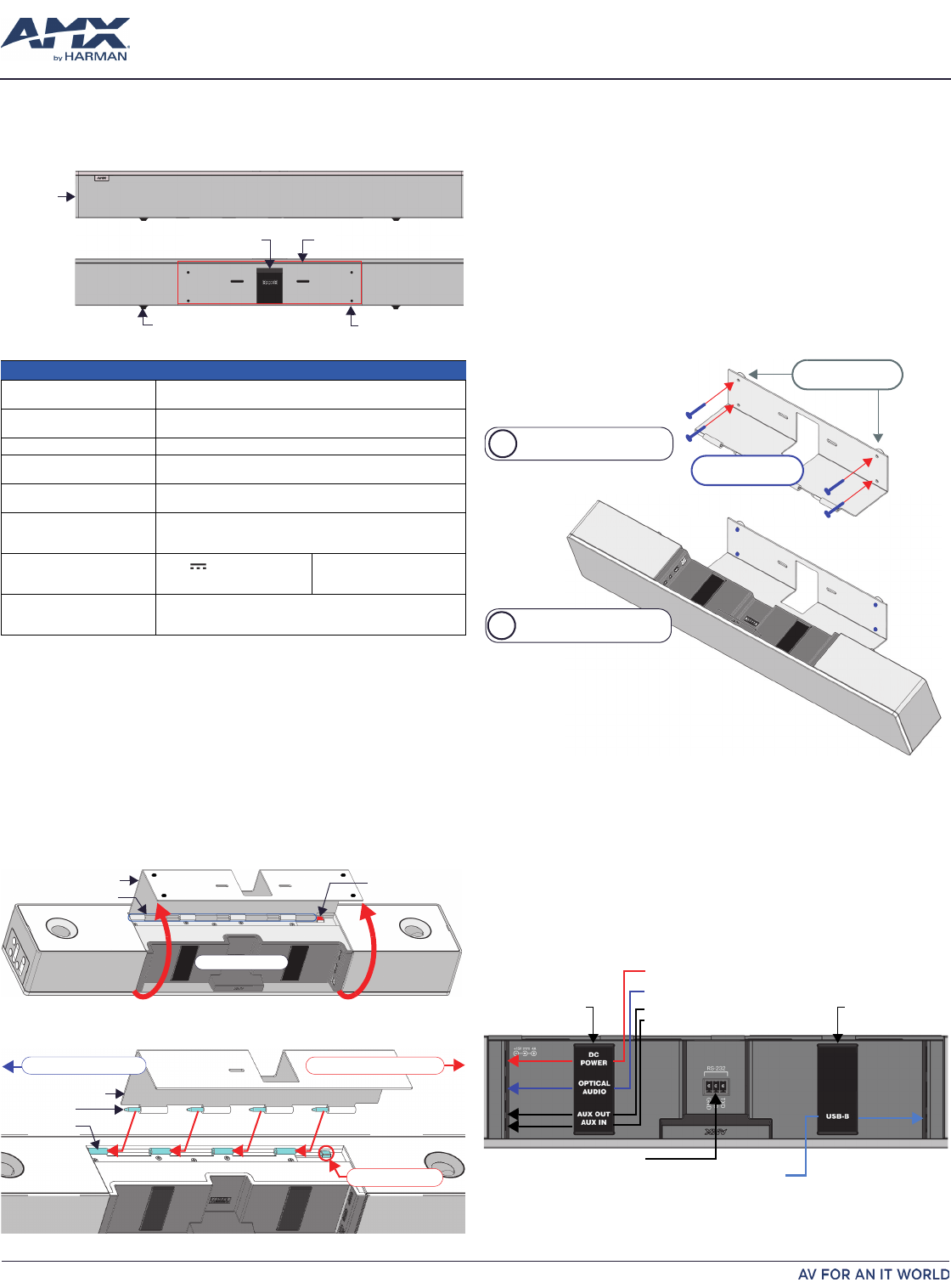
FIG. 1 ACV-2100 (FRONT/REAR VIEWS)
PRODUCT SPECIFICATIONS
MODELS AVAILABLE • ACV-2100GR, Grey (FG4121-00GR)
• ACV-2100BL, Black (FG4121-00BL)
DIMENSIONS (HWD) • 3" x 23 1/2" x 3 15/16" (76 mm x 590 mm x 100 mm)
• Depth with optional wall mount spacers: 4 1/8” (105 mm)
WEIGHT 6.3 lbs (2.86 kg)
ACTIVE POWER REQUIREMENTS • ~100-240V, 1.3A max
• Only use the included power supply
REGULATORY COMPLIANCE FCC 47 CFR Part 15, Subpart C / Subpart B (emissions)
EN 55024, EN 60950-1, IEC/EN/UL 60065:2014
ENVIRONMENTAL • Temperature (Operating): 32° F to 122° F (0° C to 50° C)
• Temperature (Storage): -4° F to 158° F (-20° C to 70° C)
• Humidity (Operating): 5% to 85% RH non-condensing
INCLUDED ACCESSORIES • 15V / 4A.Power Supply
• Remote Control
• 6’ USB 2.0 Cable
• 5mm Wall Mount Spacers (4)
•Lock-Down Screws (2)
OPTIONAL ACCESSORIES
• CBL-USB-FL2-16, USB 2.0 16ft Extension Cable (FG10-2220-16)
• CBL-USB-FL2-33, USB 2.0 33ft Extension Cable (FG10-2220-33)
• ACR-5100, Meeting Collaboration System (FG4051-00)
FIG. 2 ACV-2100 BOTTOM VIEW - OPENING THE WALL MOUNT BRACKET
FIG. 3 ACV-2100 BOTTOM VIEW - REMOVING THE WALL MOUNT BRACKET
Front
Rear mounting holes (x4)
Wall Mount Bracket
Rubber feet (removable, x2)
Side Panel
Keypad
Cable Cutout
Bracket/Door
Hinges/Pins
Release Button
Connector Bay
Bracket/Door
Pins (x4)
Hinges (x4)
Slide pins in to install Slide pins out to remove
Release Button
FIG. 4 WALL MOUNTING THE ACV-2100
FIG. 5 ACV-2100 CONNECTOR BAY
Mount the Bracket to the
wall via 4 mounting screws
Attach the ACV-2100 to the
Bracket via hinges & pins
b
a
mounting screws
(x4, not included)
mounting spacers
(x4, optional)
Analog audio input
Analog audio output
Optical audio input
DC Power input
USB (Type B)
cable strap cable strap
RS-232 (3-pin captive wire)
© 2017 Harman. All rights reserved. Modero, AMX, AV FOR AN IT WORLD, HARMAN, and their respective logos are registered trademarks of
HARMAN. Oracle, Java and any other company or brand name referenced may be trademarks/registered trademarks of their respective companies.
AMX does not assume responsibility for errors or omissions. AMX also reserves the right to alter specifications without prior notice at any time.
The AMX Warranty and Return Policy and related documents can be viewed/downloaded at www.amx.com.
3000 RESEARCH DRIVE, RICHARDSON, TX 75082 AMX.com | 800.222.0193 | 469.624.8000 | +1.469.624.7400 | fax 469.624.7153
AMX (UK) LTD, AMX by HARMAN - Unit C, Auster Road, Clifton Moor, York, YO30 4GD United Kingdom • +44 1904-343-100 • www.amx.com/eu/
REV: A
Last Revised: 10/30/2017
Rotating the ACV-2100 Into the Seated Position
After connecting all cables, close the Bracket to return the ACV-2100 to it’s seated
position. The Bracket is secured via internal magnets (FIG. 6):
Installing Lock-Down Screws
The ACV-2100 comes with two (flat-head) Lock-Down Screws that can be added after
the ACV-2100 has been installed and connected. The Lock-Down Screws prevent the
Bracket from being opened accidentally. With the Bracket/Connector Bay Door
closed, install the Lock-Down Screws in the bottom panel (FIG. 7):
Side Panel Keypad
All controls and LEDs are on the left side panel of the ACV-2100 (FIG. 8):
Volume and Mute Controls
The ACV-2100 features a 10W/channel stereo amplifier, speakers, microphones, and
DSP algorithms by JBL.
•Use the Volume Up/Down buttons to adjust speaker volume.
•Use the Mute Speaker and Mute Microphone buttons to enable/disable the
speakers and microphone. Note that these buttons illuminate to indicate when
the sound functions are muted.
Remote Control
The ACV-2100 includes a wireless remote control (FIG. 9):
Pairing the Remote Control to the Acendo Vibe
1. With the ACV-2100 powered on, press the Bluetooth button on the Side Panel
Keypad (see FIG. 8) to turn Bluetooth on. This button lights to indicate that
Bluetooth is on.
2. Press the Bluetooth button on the Remote Control. The button flashes to indicate
that the remote is in pairing mode. When the pairing is complete, the Bluetooth
LED on the remote remains lit while the devices are paired.
Note: If the pairing is not immediately successful, press the Bluetooth button on the
Remote Control a second time.
Pairing the Acendo Vibe with a Bluetooth Source Device
1. Press the Bluetooth button on the left side panel of the ACV-2100 to turn Bluetooth
on and initiate pairing (FIG. 8).
2. On the source device, verify that Bluetooth pairing is enabled, and look for
“Acendo Vibe” (or custom discoverable name) as a found device. Select the
Acendo Vibe device for pairing.
Note: The Bluetooth LED on the ACV-2100 side panel lights to indicate that the
paired Bluetooth device is currently selected as the audio source.
Acendo Vibe Configuration Tool
The ACV-2100 is configured via the Acendo Vibe Configuration Tool software (available
to download from AMX). In most cases the default settings should work fine without any
need for adjustment. Configurable settings include:
•Bluetooth (On/Off) - Click to toggle On/Off (default = On).
•Bluetooth Device Name - Enter a new name for the Acendo Vibe unit. This is the
device name that will indicate this Acendo Vibe on the Bluetooth network.
(default = “Acendo Vibe”)
•Aux Out Gain - Select Variable or Fixed (default = Variable).
•Default Volume - Enter a value (0-100) for the default output volume
(default = 50).
•Automatic Audio Switching - Toggle On/Off (default = On).
•Use the File (Open, Save and Transfer) options to save the current settings, open
an existing config file, and transfer new settings or firmware to an Acendo Vibe
via USB connection.
Note: For details, see the ACENDO VIBE Instruction Manual, available to view or
download from www.amx.com.
Setup Mode
In order for the Acendo Vibe Configuration Tool to communicate with the Acendo
Vibe, the unit must be in Setup Mode. To place the ACV-2100 in Setup Mode, press the
Source and Mic Mute keys simultaneously for 5 seconds (see FIG. 1). All of the LEDs blink
to indicate that the unit is in Setup Mode.
While in Setup Mode, the ACV-2100’s USB interface is enabled, and the Virtual COM
port is visible to an attached PC.
Additional Documentation
For instructions on configuring the Acendo Vibe via the Acendo Vibe Configuration
Tool, as well as file transfer, firmware updates, programming and troubleshooting info,
see the Acendo Vibe Instruction Manual, available to view or download from
www.amx.com.
ACV-2100 CONNECTIONS
DC POWER Connect the included 15V power supply to this barrel connector. Only use the power
supply included with the ACV-2100.
OPTICAL AUDIO: Use this TOSLINK connector to receive Optical Stereo Input from an audio source device.
AUX OUT Use this 1/8” mini-stereo connector to send analog stereo sound from the ACV-2100 to an
auxiliary device.
AUX IN Use this 1/8” mini-stereo connector to receive analog stereo sound from an analog audio
source device.
USB Use the USB 2.0 Type-B port to connect a PC/laptop to the ACV-2100 as a source device.
Acendo Vibe is plug-and-play with PC/laptop using standard UAC/UVC drivers.
The USB connection is also used to configure the ACV-2100 via the AMX Acendo Vibe
configuration application and for file transfers.
RS-232 3-pin captive-wire connector provides serial communication with the Acendo Vibe. Refer to
the Acendo Vibe Instruction Manual for serial command definitions.
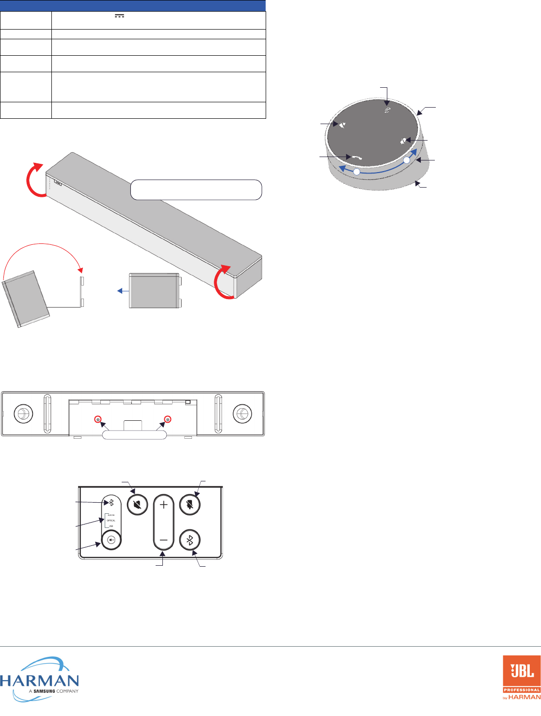
FIG. 6 ROTATING THE ACV-2100 INTO ITS SEATED POSITION
FIG. 7 ACV-2100 BOTTOM VIEW - LOCK DOWN SCREW LOCATIONS
FIG. 8 ACV-2100 LEFT SIDE PANEL KEYPAD
Rotate the ACV-2100 into seated position
(Bracket is secured with magnets)
open closed
front
Lock-Down Screws
Input LEDs
(light to indicate
the active source)
Source Select
(press to cycle through
the source options)
Mute speaker Mute microphone
Volume Up/Down Bluetooth pairing
Bluetooth (lights to
indicate Bluetooth is the
selected audio source)
FIG. 9 ACENDO VIBE REMOTE CONTROL
Bluetooth
Mute Microphone
Mute Speaker
End Call
Source Select button
(on back side)
(press to enter pairing mode)
Volume Up/Down
+
-(rotate ring to adjust)
Battery Compartment (bottom panel)
Unlock & twist to open