AMX MYTTX MyTurn Source Selector Button User Manual 93 0554 21 HPA MYT TX RX QuickStartGuide REV A
AMX LLC MyTurn Source Selector Button 93 0554 21 HPA MYT TX RX QuickStartGuide REV A
AMX >
Contents
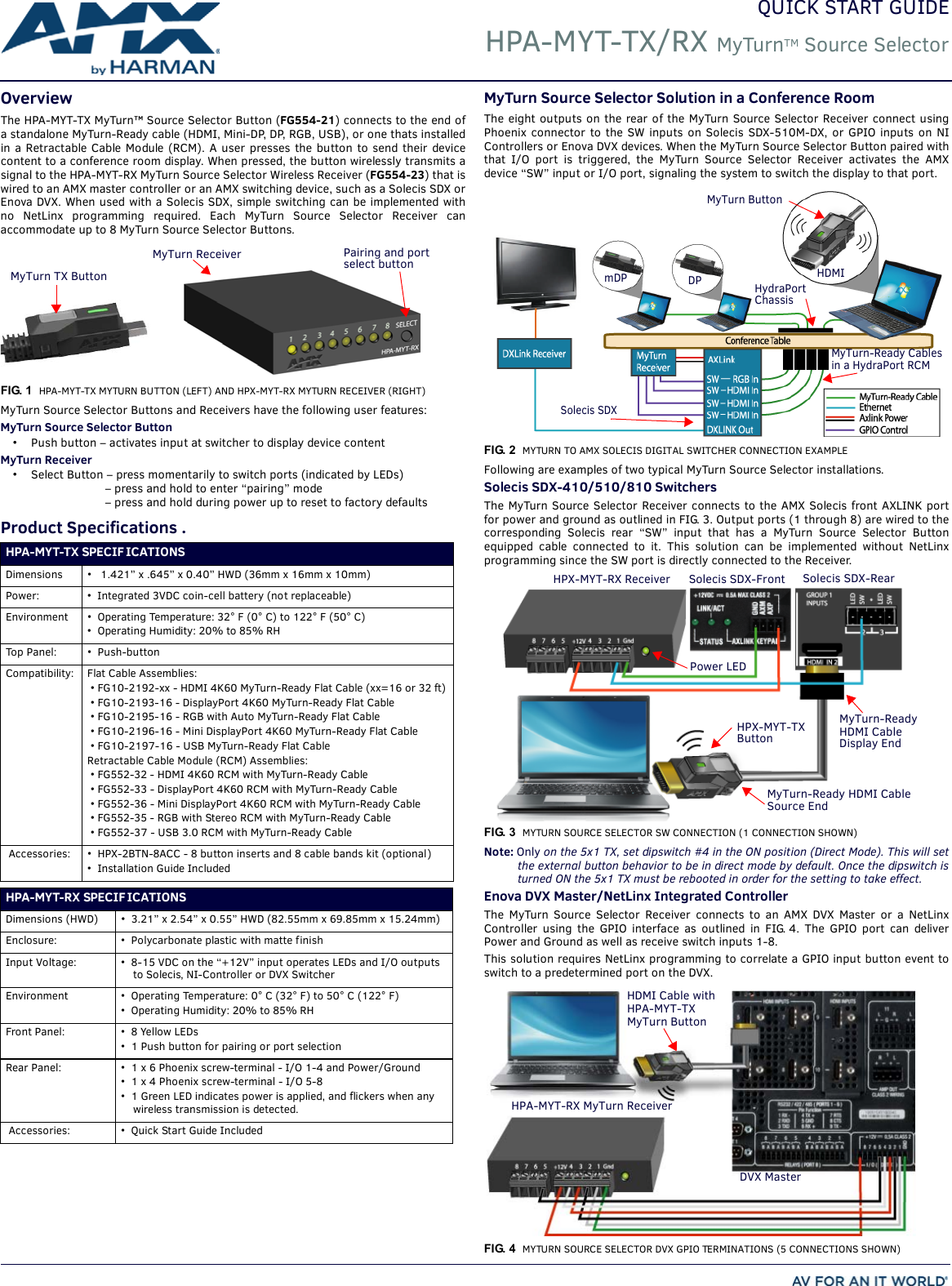
- 1. 6 CONFIDENTIAL SHORT TERM HPA-MYT-TX User manual 1 of 2
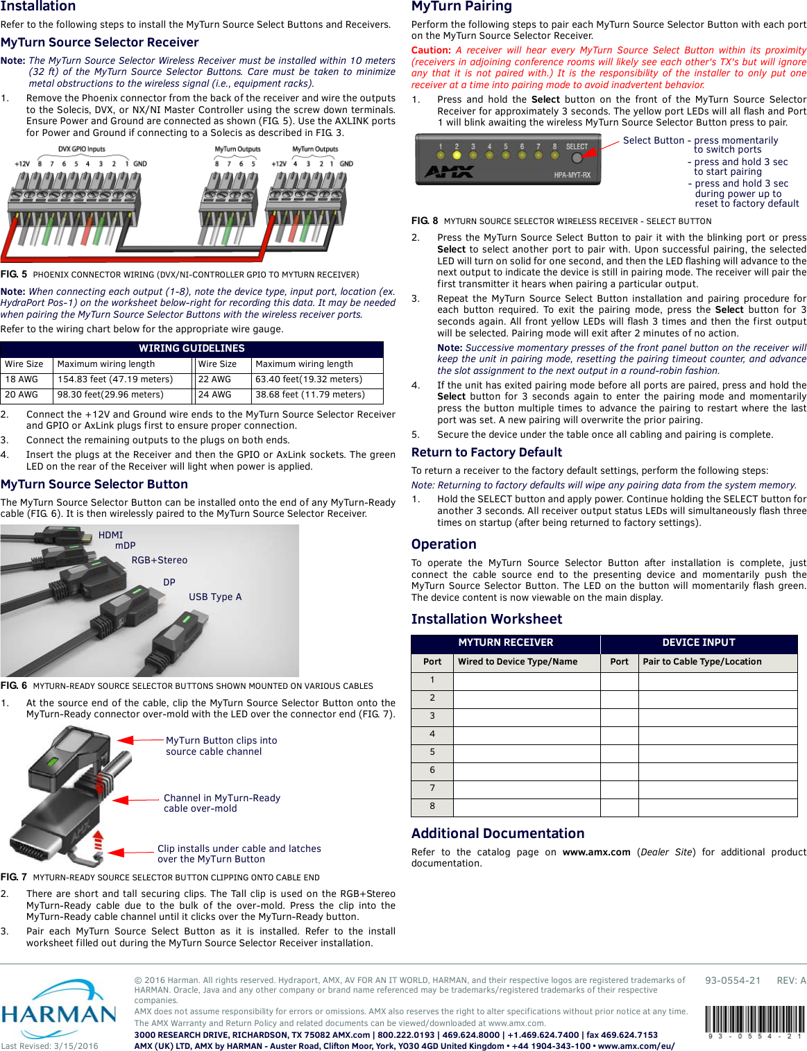
- 2. 6 CONFIDENTIAL SHORT TERM HPA-MYT-TX User manual 2 of 2
6 CONFIDENTIAL SHORT TERM HPA-MYT-TX User manual 1 of 2