AMX SAA596803 SAA5968-03 User Manual
AMX LLC SAA5968-03
UserManual.wiki
>
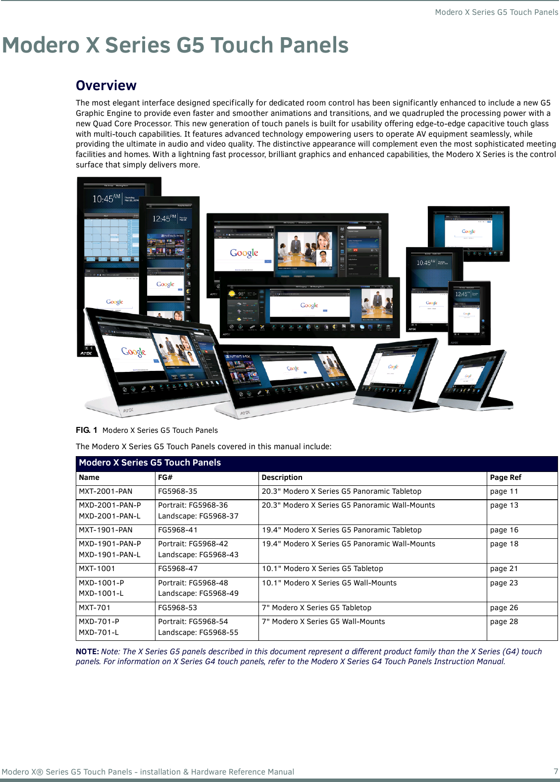
AMX
>
SAA596803 User Manual
User Manual
Navigation menu
Upload a User Manual
Namespaces
Wiki Guide
HTML
PDF
Info
Views
User Manual
Discussion / Help
Navigation
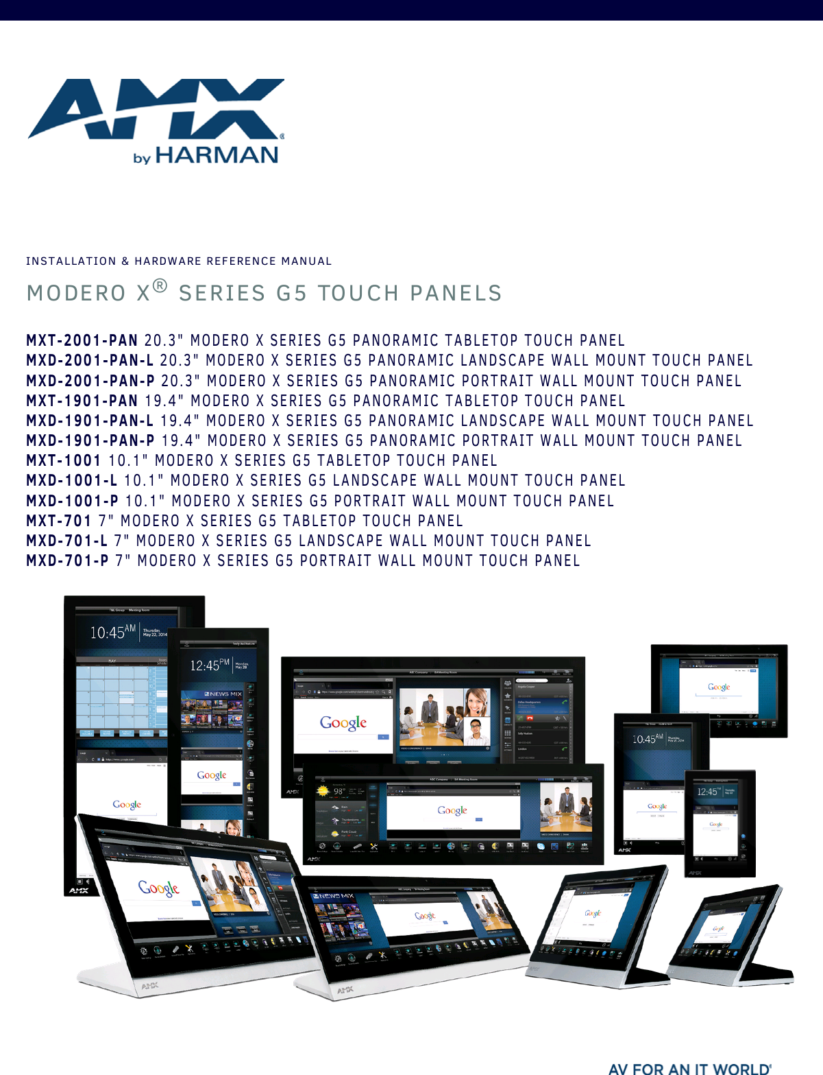

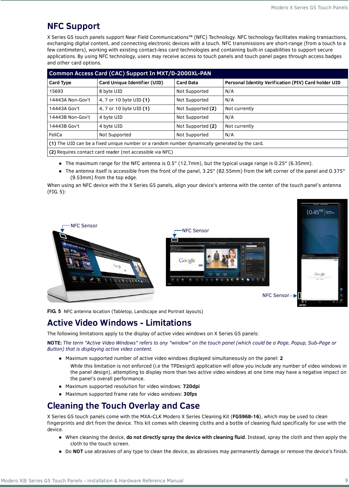
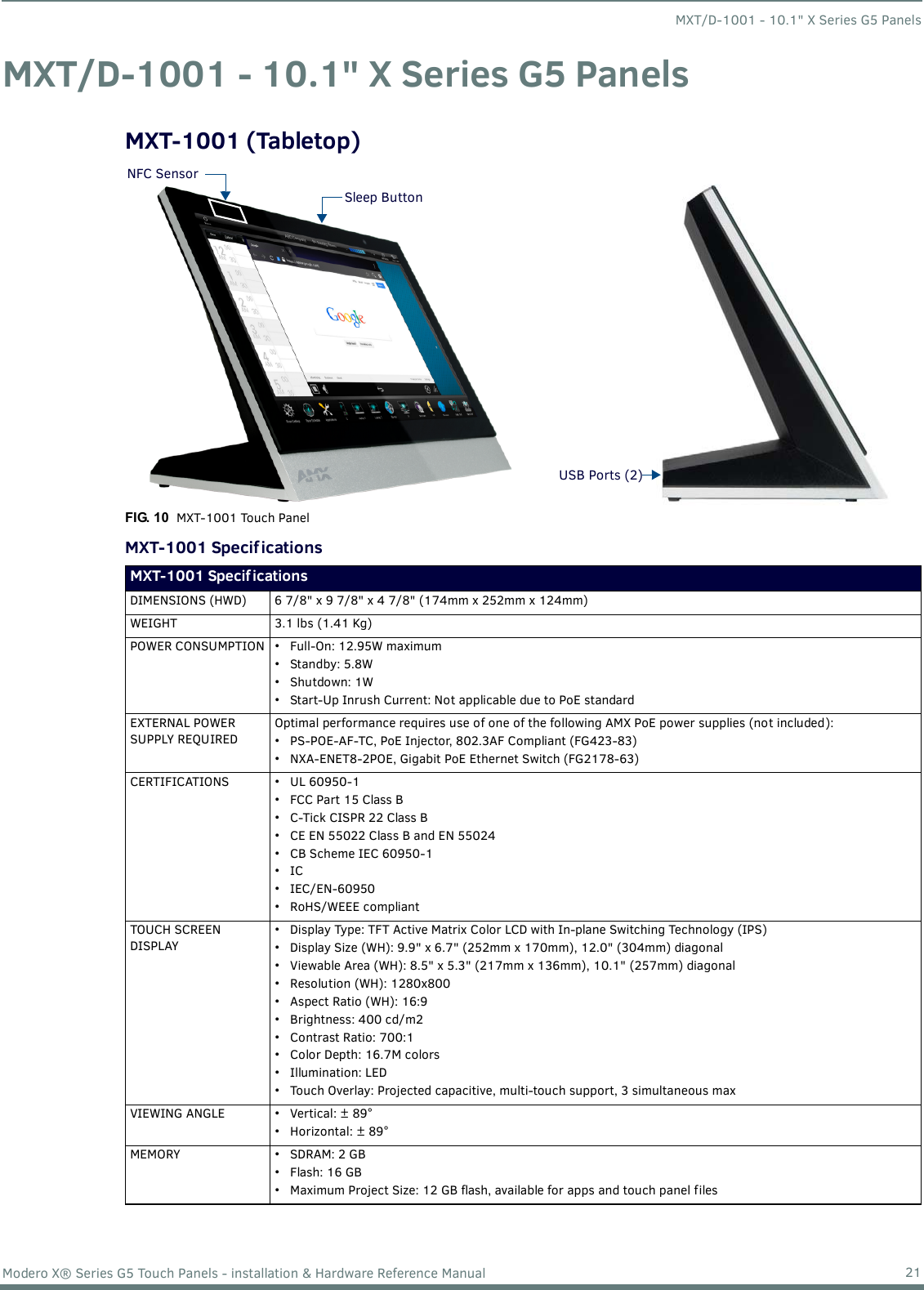
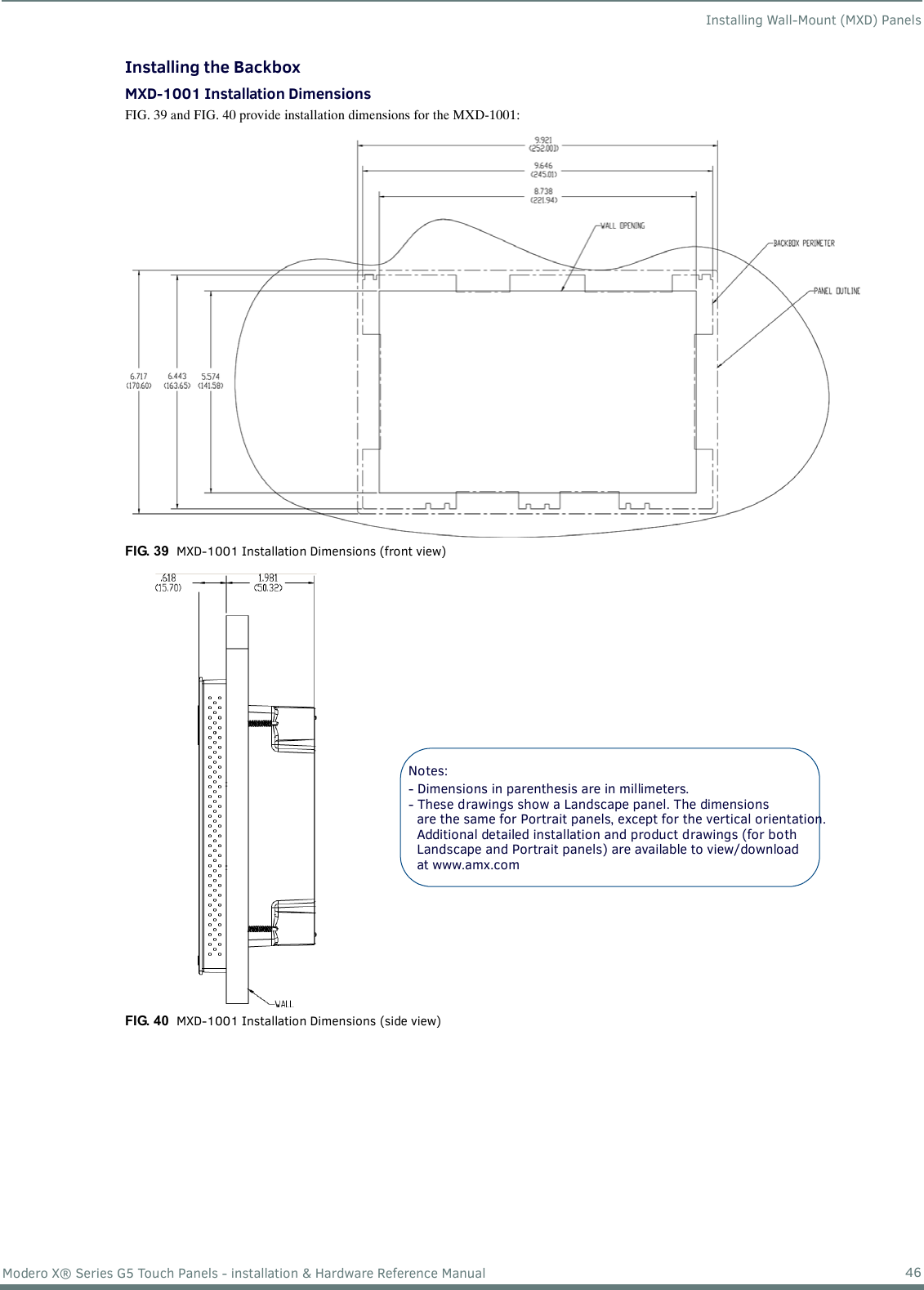
![Installing Wall-Mount (MXD) Panels40Modero X® Series G5 Touch Panels - installation & Hardware Reference Manual4. Remove any knockouts as needed on either long dimension of the Backbox to facilitate incoming wiring and pull the wiring through the resultant holes.5. Push the Backbox into the wall opening. Insure that the locking tabs lie flush against the Backbox, and that the Backbox goes freely into the opening. 6. Extend the locking tabs on the sides of the Backbox by tightening the screws inside the box until snug. NOTE: The maximum recommended torque to screw in the locking tabs on the plastic Backbox is 5 IN-LB [56 N-CM]. Applying excessive torque while tightening the tab screws, such as with powered screwdrivers, can strip out the locking tabs or damage the plastic Backbox.Not all of the tabs must be extended to lock the Backbox in place, but extending a minimum of the top and bottom tabs is highly recommended. Apply enough pressure to the screw head to keep the box flush with the wall: this ensures that the locking tabs will tighten up against the inside of the wall.The Backbox is clear to allow visual confirmation that the tabs have been extended and are gripping the wall, as well as in assisting with removal if necessary.For additional strength, #4 mounting screws (not included) may be secured through circular holes located at the left and right sides of the MXD-2001-PAN (see FIG. 30). In order to prevent damage to the touch panel, make sure that these are flush with the Backbox.7. Insert each connector into its corresponding location along the back of the device (FIG. 31).FIG. 30 MXD-1901-PAN Backbox installation (Landscape)FIG. 31 MXD-2001-PAN / MXD-1901-PAN - rear connectors4X Installation Clampfor Wall Thickness.37 [12.01] to .98 [25.0]Cables Routed toWall Opening8X Knock OutsRemove For CableRouting As NeededMounting screwsplacement (optional)WallNote: Additional detailed installation and product drawings are available to view/download at www.amx.com Ethernet 10/100 PortType A USB Port(limited access)13.5V Power Port](https://usermanual.wiki/AMX/SAA596803/User-Guide-2754017-Page-40.png)
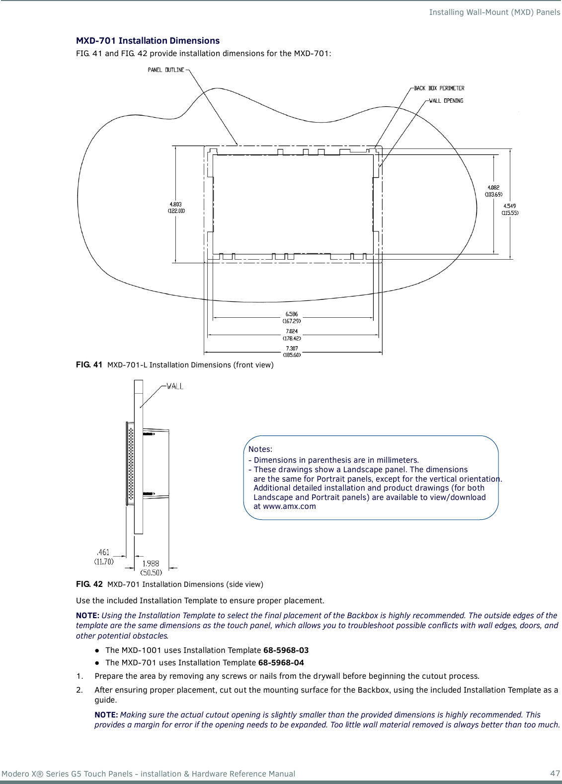
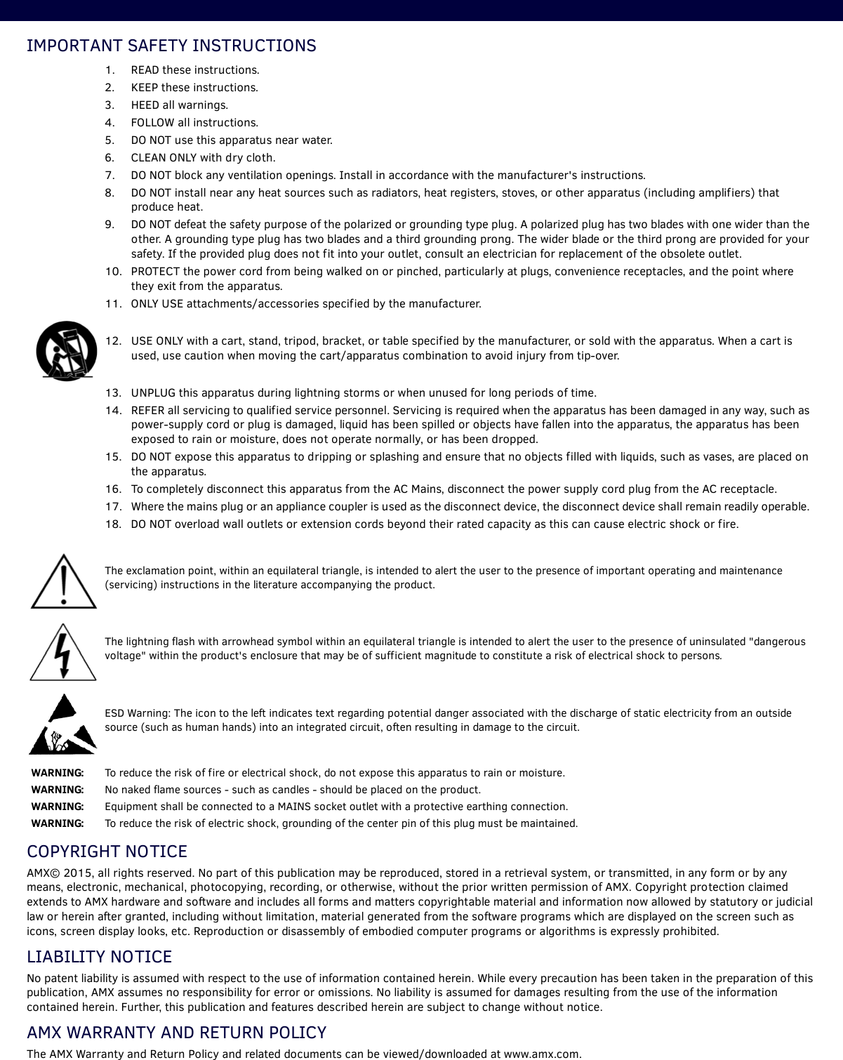
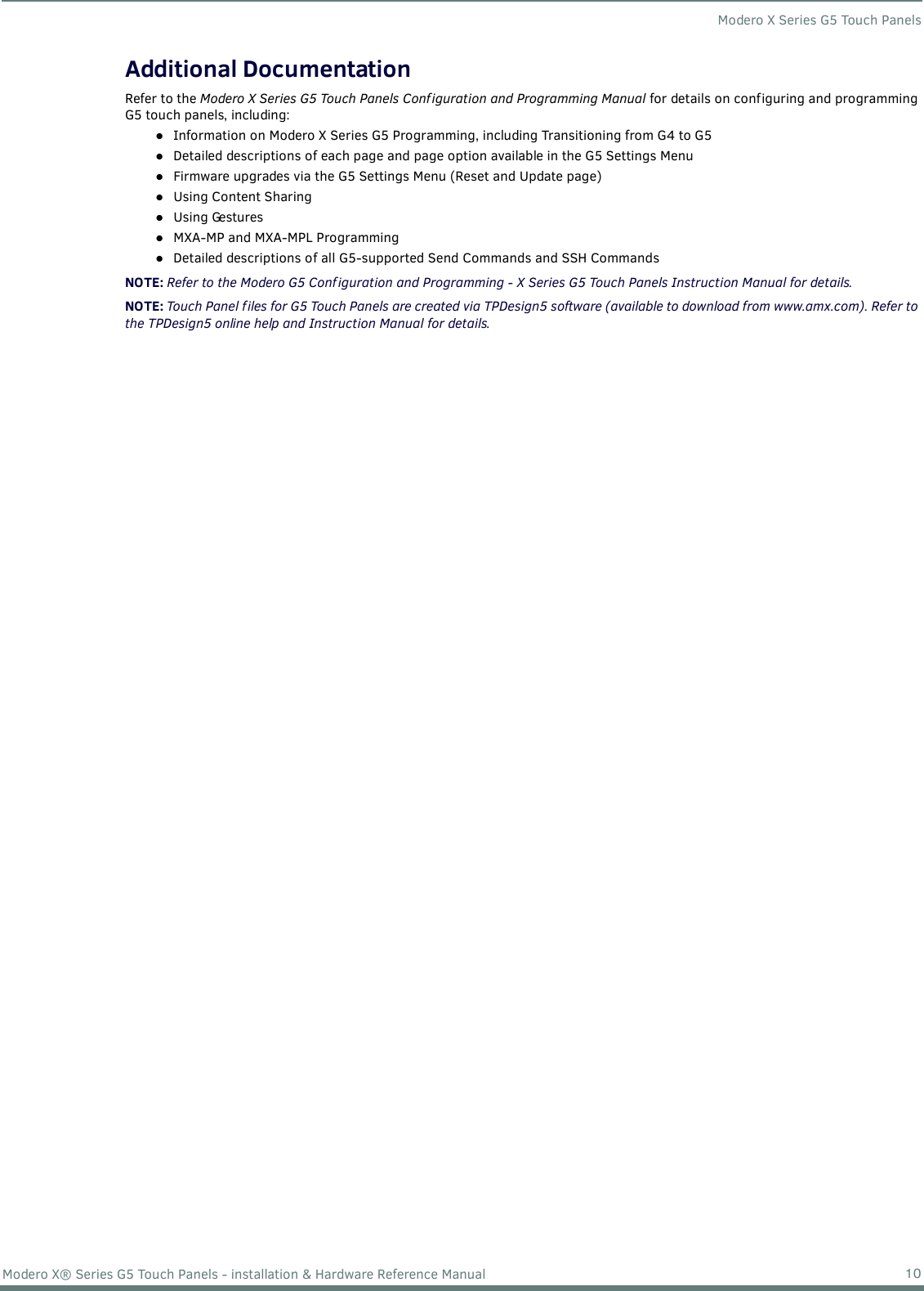
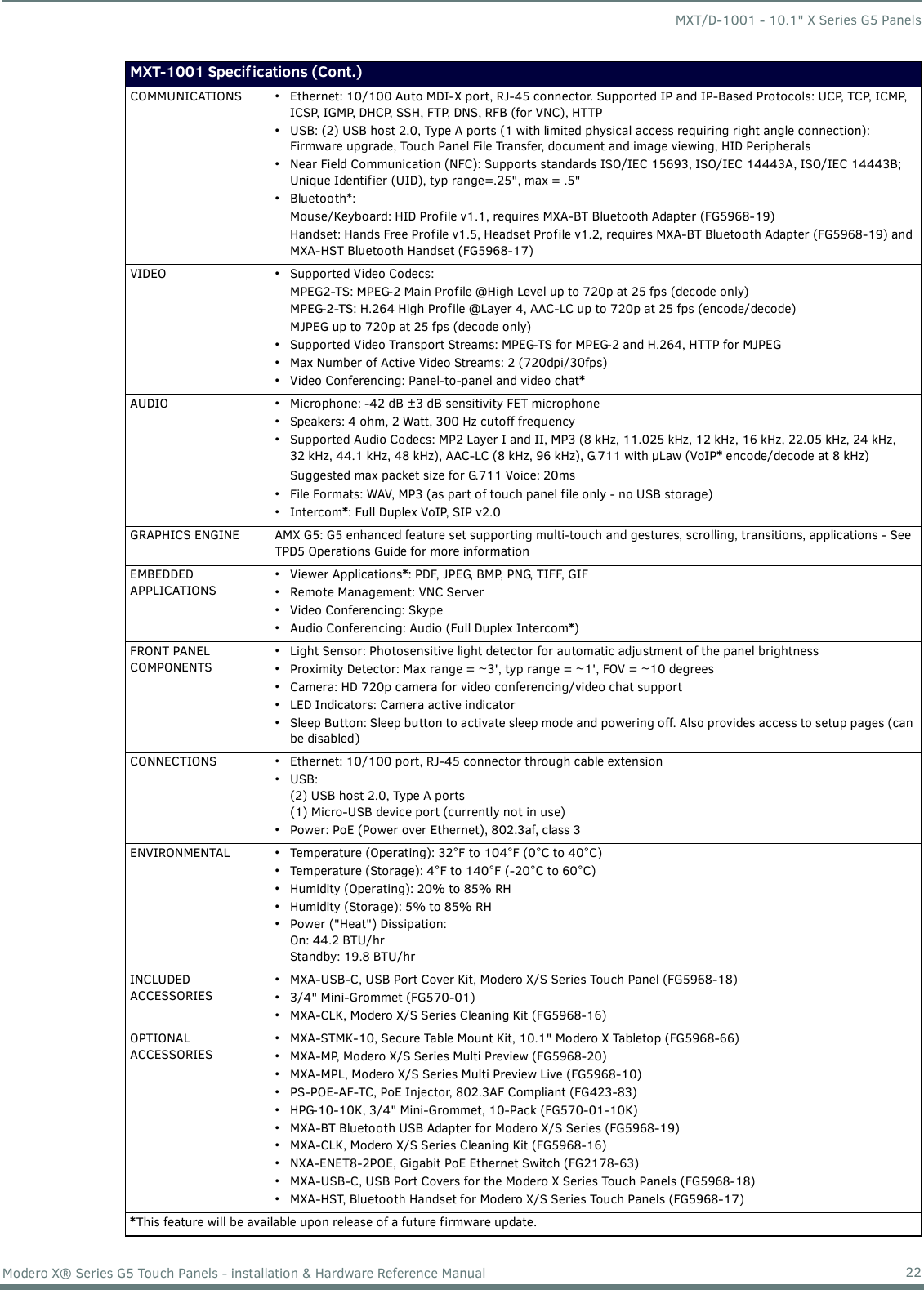
![Installing Wall-Mount (MXD) Panels48Modero X® Series G5 Touch Panels - installation & Hardware Reference Manual3. Thread the incoming Ethernet and USB cables through the surface opening (FIG. 43 and FIG. 44). Note that these figures show a landscape panel but the installation of a portrait panel is essentially the same, other than the vertical orientation.Leave enough slack in the wiring to accommodate any re-positioning of the panel. FIG. 43 shows the MXD-1001 Backbox installation: FIG. 43 MXD-1001 Backbox Installation (Landscape)#4 Screws4X Knock-OutsRemove for CableRouting as Needed4X Installation Clampfor Wall Thickness.31 [12.0] to .98 [.25.0]Note: Additional detailed installation and product drawings are available to view/download at www.amx.com](https://usermanual.wiki/AMX/SAA596803/User-Guide-2754017-Page-48.png)
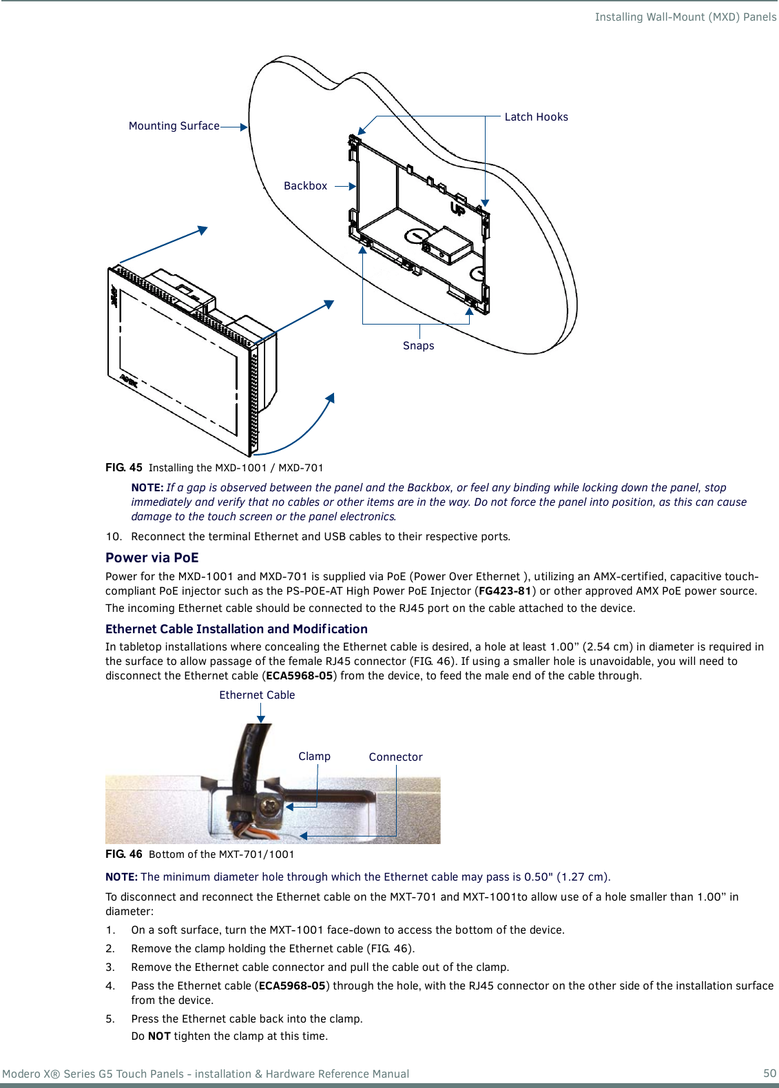
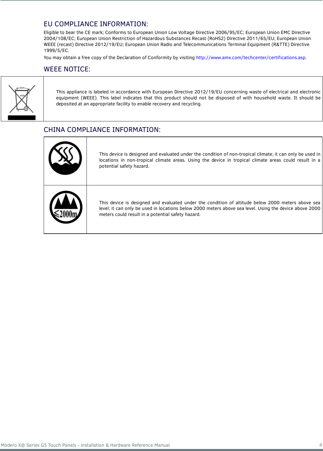
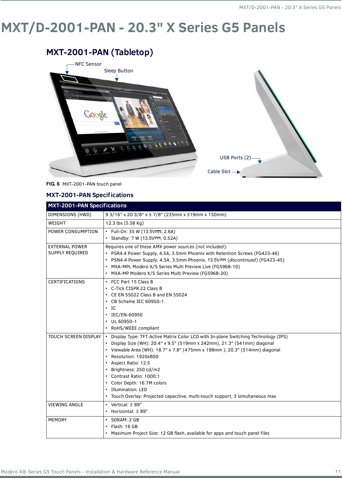
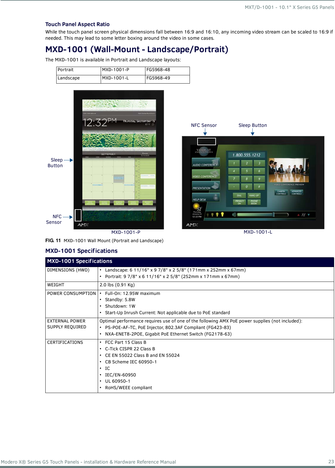
![Installing Wall-Mount (MXD) Panels49Modero X® Series G5 Touch Panels - installation & Hardware Reference ManualFIG. 44 shows the MXD-701 Backbox installation: 4. Remove any knockouts as needed on either long dimension of the Backbox to facilitate incoming wiring and pull the wiring through the resultant holes.5. Push the Backbox into the mounting surface. Insure that the locking tabs lie flush against the Backbox and that the Backbox goes freely into the opening. 6. Extend the locking tabs on the sides of the Backbox by tightening the screws inside the box until snug.NOTE: The maximum recommended torque to screw in the locking tabs on the plastic Backbox is 5 IN-LB [56 N-CM]. Applying excessive torque while tightening the tab screws, such as with powered screwdrivers, can strip out the locking tabs or damage the plastic Backbox.Not all of the tabs must be extended to lock the Backbox in place, but extending a minimum of the top and bottom tabs is highly recommended. Apply enough pressure to the screw head to keep the box flush with the wall: this ensures that the locking tabs will tighten up against the inside of the wall.The Backbox is clear to allow visual confirmation that the tabs have been extended and are gripping the wall, as well as in assisting with removal if necessary.For additional strength, #4 mounting screws (not included) may be secured through circular holes located at the left and right sides of the panel (FIG. 43, FIG. 44). In order to prevent damage to the touch panel, make sure that these are flush with the Backbox.7. Insert each connector into its corresponding location along the back of the panel. a. To reach the RJ45 connector, gently pull it from beneath the electronics cover. b. Attach the Ethernet cable and gently push the connection back under the cover.NOTE: Refer to the Power via PoE section on page 50 for details on PoE and Ethernet Cable Installation and Modif ication.8. Test the incoming wiring by attaching the panel connections to their terminal locations and applying power. Verify that the panel is receiving power and functioning properly to prevent repetition of the installation.NOTE: Do not disconnect the connectors from the touch panel. The unit must be installed with the attached connectors before being inserted into the mounting surface.9. Latch the panel onto the hooks on the Backbox. Push in on the bottom snaps (Landscape) or on the right (Portrait) gently but firmly until the snaps “click” to lock it down (FIG. 45).FIG. 44 MXD-701 Backbox Installation (Landscape)#4 Screws4X Knock-OutsRemove for CableRouting as Needed2X Installation Clampfor Wall Thickness.37 [12.03] to .98 [.25.0]Note: Additional detailed installation and product drawings are available to view/download at www.amx.com](https://usermanual.wiki/AMX/SAA596803/User-Guide-2754017-Page-49.png)