User Manual
INSTALLATION & HARDWARE REFERENCE MANUAL
MODERO X® SERIES G5 TOUCH PANELS
MXT-2001-PAN
20.3" MODERO X SERIES G5 PANORAMIC TABLETOP TOUCH PANEL
MXD-2001-PAN-L
20.3" MODERO X SERIES G5 PANORAMIC LANDSCAPE WALL MOUNT TOUCH PANEL
MXD-2001-PAN-P
20.3" MODERO X SERIES G5 PANORAMIC PORTRAIT WALL MOUNT TOUCH PANEL
MXT-1901-PAN
19.4" MODERO X SERIES G5 PANORAMIC TABLETOP TOUCH PANEL
MXD-1901-PAN-L
19.4" MODERO X SERIES G5 PANORAMIC LANDSCAPE WALL MOUNT TOUCH PANEL
MXD-1901-PAN-P
19.4" MODERO X SERIES G5 PANORAMIC PORTRAIT WALL MOUNT TOUCH PANEL
MXT-1001
10.1" MODERO X SERIES G5 TABLETOP TOUCH PANEL
MXD-1001-L
10.1" MODERO X SERIES G5 LANDSCAPE WALL MOUNT TOUCH PANEL
MXD-1001-P
10.1" MODERO X SERIES G5 PORTRAIT WALL MOUNT TOUCH PANEL
MXT-701
7" MODERO X SERIES G5 TABLETOP TOUCH PANEL
MXD-701-L
7" MODERO X SERIES G5 LANDSCAPE WALL MOUNT TOUCH PANEL
MXD-701-P
7" MODERO X SERIES G5 PORTRAIT WALL MOUNT TOUCH PANEL
IMPORTANT SAFETY INSTRUCTIONS
COPYRIGHT NOTICE
AMX© 2015, all rights reserved. No part of this publication may be reproduced, stored in a retrieval system, or transmitted, in any form or by any
means, electronic, mechanical, photocopying, recording, or otherwise, without the prior written permission of AMX. Copyright protection claimed
extends to AMX hardware and software and includes all forms and matters copyrightable material and information now allowed by statutory or judicial
law or herein after granted, including without limitation, material generated from the software programs which are displayed on the screen such as
icons, screen display looks, etc. Reproduction or disassembly of embodied computer programs or algorithms is expressly prohibited.
LIABILITY NOTICE
No patent liability is assumed with respect to the use of information contained herein. While every precaution has been taken in the preparation of this
publication, AMX assumes no responsibility for error or omissions. No liability is assumed for damages resulting from the use of the information
contained herein. Further, this publication and features described herein are subject to change without notice.
AMX WARRANTY AND RETURN POLICY
The AMX Warranty and Return Policy and related documents can be viewed/downloaded at www.amx.com.
1. READ these instructions.
2. KEEP these instructions.
3. HEED all warnings.
4. FOLLOW all instructions.
5. DO NOT use this apparatus near water.
6. CLEAN ONLY with dry cloth.
7. DO NOT block any ventilation openings. Install in accordance with the manufacturer's instructions.
8. DO NOT install near any heat sources such as radiators, heat registers, stoves, or other apparatus (including amplifiers) that
produce heat.
9. DO NOT defeat the safety purpose of the polarized or grounding type plug. A polarized plug has two blades with one wider than the
other. A grounding type plug has two blades and a third grounding prong. The wider blade or the third prong are provided for your
safety. If the provided plug does not fit into your outlet, consult an electrician for replacement of the obsolete outlet.
10. PROTECT the power cord from being walked on or pinched, particularly at plugs, convenience receptacles, and the point where
they exit from the apparatus.
11. ONLY USE attachments/accessories specified by the manufacturer.
12. USE ONLY with a cart, stand, tripod, bracket, or table specified by the manufacturer, or sold with the apparatus. When a cart is
used, use caution when moving the cart/apparatus combination to avoid injury from tip-over.
13. UNPLUG this apparatus during lightning storms or when unused for long periods of time.
14. REFER all servicing to qualified service personnel. Servicing is required when the apparatus has been damaged in any way, such as
power-supply cord or plug is damaged, liquid has been spilled or objects have fallen into the apparatus, the apparatus has been
exposed to rain or moisture, does not operate normally, or has been dropped.
15. DO NOT expose this apparatus to dripping or splashing and ensure that no objects filled with liquids, such as vases, are placed on
the apparatus.
16. To completely disconnect this apparatus from the AC Mains, disconnect the power supply cord plug from the AC receptacle.
17. Where the mains plug or an appliance coupler is used as the disconnect device, the disconnect device shall remain readily operable.
18. DO NOT overload wall outlets or extension cords beyond their rated capacity as this can cause electric shock or fire.
The exclamation point, within an equilateral triangle, is intended to alert the user to the presence of important operating and maintenance
(servicing) instructions in the literature accompanying the product.
The lightning flash with arrowhead symbol within an equilateral triangle is intended to alert the user to the presence of uninsulated "dangerous
voltage" within the product's enclosure that may be of sufficient magnitude to constitute a risk of electrical shock to persons.
ESD Warning: The icon to the left indicates text regarding potential danger associated with the discharge of static electricity from an outside
source (such as human hands) into an integrated circuit, often resulting in damage to the circuit.
WARNING: To reduce the risk of fire or electrical shock, do not expose this apparatus to rain or moisture.
WARNING: No naked flame sources - such as candles - should be placed on the product.
WARNING: Equipment shall be connected to a MAINS socket outlet with a protective earthing connection.
WARNING: To reduce the risk of electric shock, grounding of the center pin of this plug must be maintained.
3
Modero X® Series G5 Touch Panels - installation & Hardware Reference Manual
ESD WARNING
WARNING: This product is intended to be operated ONLY from the voltages listed on the back panel or the recommended, or
included, power supply of the product. Operation from other voltages other than those indicated may cause irreversible
damage to the product and void the products warranty. The use of AC Plug Adapters is cautioned because it can allow the
product to be plugged into voltages in which the product was not designed to operate. If the product is equipped with a
detachable power cord, use only the type provided with your product or by your local distributor and/or retailer. If you are
unsure of the correct operational voltage, please contact your local distributor and/or retailer.
FCC AND CANADA EMC COMPLIANCE INFORMATION:
This device complies with part 15 of the FCC Rules. Operation is subject to the following two conditions:
(1) This device may not cause harmful interference, and (2) this device must accept any interference received, including
interference that may cause undesired operation.
NOTE: This equipment has been tested and found to comply with the limits for a Class B digital device, pursuant to part 15 of
the FCC Rules. These limits are designed to provide reasonable protection against harmful interference in a residential
installation. This equipment generates, uses and can radiate radio frequency energy and, if not installed and used in
accordance with the instructions, may cause harmful interference to radio communications. However, there is no guarantee
that interference will not occur in a particular installation. If this equipment does cause harmful interference to radio or
television reception, which can be determined by turning the equipment off and on, the user is encouraged to try to correct
the interference by one or more of the following measures:
•Reorient or relocate the receiving antenna.
•Increase the separation between the equipment and receiver.
•Connect the equipment into an outlet on a circuit different from that to which the receiver is connected.
•Consult the dealer or an experienced radio/TV technician for help.
Approved under the verification provision of FCC Part 15 as a Class B Digital Device.
Caution: Changes or modifications not expressly approved by the manufacturer could void the user's authority to operate this
device.
CAN ICES-3 (B)/NMB-3(B)
WIRELESS TRANSMITTER COMPLIANCE INFORMATION:
The term "IC:" before the radio certification number only signifies that Industry Canada technical specifications were met.
Le terme "IC:" avant le numéro de certification radio signifie seulement que les spécifications techniques d'Industrie Canada
ont été respectées.
This device complies with part 15 of the FCC Rules and the applicable Industry Canada license-exempt RSS standard(s).
Operation is subject to the following two conditions: (1) this device may not cause harmful interference, and (2) this device
must accept any interference, including interference that may cause undesired operation of the device.
Le présent appareil est conforme aux CNR d'Industrie Canada applicables aux appareils radio exempts de licence.
L'exploitation est autorisée aux deux conditions suivantes : (1) l'appareil ne doit pas produire de brouillage, et (2) l'utilisateur
de l'appareil doit accepter tout brouillage radioélectrique subi, même si le brouillage est susceptible d'en compromettre le
fonctionnement.
This equipment complies with FCC and IC radiation exposure limits set forth for an uncontrolled environment. This equipment
should be installed and operated with minimum distance 20cm between the radiator and your body. This transmitter must not
be co-located or operating in conjunction with any other antenna or transmitter.
Cet appareil est conforme à FCC et IC l'exposition aux rayonnements limites fixées pour un environnement non contrôlé. Cet
appareil doit être installé et utilisé avec une distance minimale de 20 cm entre le radiateur et votre corps. Cet transmetteur ne
doit pas être co-situé ou opérant en liaison avec toute autre antenne ou transmetteur.
To avoid ESD (Electrostatic Discharge) damage to sensitive components, make sure you are properly grounded before
touching any internal materials.
When working with any equipment manufactured with electronic devices, proper ESD grounding procedures must be
followed to make sure people, products, and tools are as free of static charges as possible. Grounding straps, conductive
smocks, and conductive work mats are specifically designed for this purpose.
Anyone performing field maintenance on AMX equipment should use an appropriate ESD field service kit complete with at
least a dissipative work mat with a ground cord and a UL listed adjustable wrist strap with another ground cord
WARNING: Do Not Open! Risk of Electrical Shock. Voltages in this equipment are
hazardous to life. No user-serviceable parts inside. Refer all servicing to qualified
service personnel.
Place the equipment near a main power supply outlet and make sure that you can
easily access the power breaker switch.
4
Modero X® Series G5 Touch Panels - installation & Hardware Reference Manual
EU COMPLIANCE INFORMATION:
Eligible to bear the CE mark; Conforms to European Union Low Voltage Directive 2006/95/EC; European Union EMC Directive
2004/108/EC; European Union Restriction of Hazardous Substances Recast (RoHS2) Directive 2011/65/EU; European Union
WEEE (recast) Directive 2012/19/EU; European Union Radio and Telecommunications Terminal Equipment (R&TTE) Directive
1999/5/EC.
You may obtain a free copy of the Declaration of Conformity by visiting http://www.amx.com/techcenter/certifications.asp.
WEEE NOTICE:
CHINA COMPLIANCE INFORMATION:
This appliance is labeled in accordance with European Directive 2012/19/EU concerning waste of electrical and electronic
equipment (WEEE). This label indicates that this product should not be disposed of with household waste. It should be
deposited at an appropriate facility to enable recovery and recycling.
This device is designed and evaluated under the condition of non-tropical climate; it can only be used in
locations in non-tropical climate areas. Using the device in tropical climate areas could result in a
potential safety hazard.
This device is designed and evaluated under the condition of altitude below 2000 meters above sea
level; it can only be used in locations below 2000 meters above sea level. Using the device above 2000
meters could result in a potential safety hazard.

Table o f Co ntents
5
Modero X® Series G5 Touch Panels - installation & Hardware Reference Manual
Table of Contents
Modero X Series G5 Touch Panels ....................................................................7
Overview ........................................................................................................................... 7
Sleep Button ...................................................................................................................... 8
Powering On/Off X Series G5 Panels ...................................................................................................... 8
Configuration and Programming ...................................................................................... 8
Bluetooth Support ............................................................................................................. 8
NFC Support ...................................................................................................................... 9
Active Video Windows - Limitations .................................................................................. 9
Cleaning the Touch Overlay and Case............................................................................... 9
Additional Documentation.............................................................................................. 10
MXT/D-2001-PAN - 20.3" X Series G5 Panels ................................................11
MXT-2001-PAN (Tabletop) ............................................................................................ 11
MXT-2001-PAN Specifications ............................................................................................................ 11
MXD-2001-PAN (Wall-Mount - Landscape/Portrait) ..................................................... 13
MXD-2001-PAN Specifications ............................................................................................................ 13
MXT/D-1901-PAN - 19.4" X Series G5 Panels ................................................16
MXT-1901-PAN (Tabletop) ............................................................................................ 16
MXT-1901-PAN Specifications ............................................................................................................. 16
MXD-1901-PAN (Wall-Mount - Landscape/Portrait) ..................................................... 18
MXD-1901-PAN Specifications ............................................................................................................ 18
MXT/D-1001 - 10.1" X Series G5 Panels ........................................................21
MXT-1001 (Tabletop)..................................................................................................... 21
MXT-1001 Specifications ..................................................................................................................... 21
Touch Panel Aspect Ratio................................................................................................................................... 23
MXD-1001 (Wall-Mount - Landscape/Portrait) .............................................................. 23
MXD-1001 Specifications ..................................................................................................................... 23
Touch Panel Aspect Ratio................................................................................................................................... 25
MXT/D-701 - 7" X Series G5 Panels ................................................................26
MXT-701 (Tabletop) ....................................................................................................... 26
MXT-701 Specifications ....................................................................................................................... 26
Touch Panel Aspect Ratio................................................................................................................................... 27
MXD-701 (Wall-Mount - Landscape/Portrait)................................................................. 28
MXD-701 Specifications ....................................................................................................................... 28
Touch Panel Aspect Ratio................................................................................................................................... 30
Installing Tabletop (MXT) Panels ...................................................................31
MXT-2001-PAN / MXT-1901-PAN.................................................................................. 31
Connector Locations - MXT-2001-PAN / MXT-1901-PAN.................................................................... 31

Table o f Co ntents
6
Modero X® Series G5 Touch Panels - installation & Hardware Reference Manual
MXT-1001 / MXT-701 ..................................................................................................... 32
Connector Locations - MXT-1001/MXT-701........................................................................................ 32
Power via 13.5V ....................................................................................................................................... 32
Wiring a 13.5V Power Connection ..................................................................................................................... 32
Power via PoE ....................................................................................................................................... 32
Ethernet Cable Installation and Modification..................................................................................................... 33
Installing Wall-Mount (MXD) Panels ...............................................................34
A Note About Wall and Rack Installation ....................................................................... 34
Installation Recommendations ............................................................................................................ 35
MXD-2001-PAN / MXD-1901-PAN Installation ............................................................... 35
Installing the MXD-2001-PAN / MXD-1901-PAN Into a Wall ............................................................... 35
MXD-2001-PAN Dimensions............................................................................................................................... 36
MXD-1901-PAN Dimensions............................................................................................................................... 37
Installing the Backbox .......................................................................................................................... 38
MXD-2001-PAN Installation Dimensions ........................................................................................................... 38
MXD-1901-PAN Installation Dimensions ........................................................................................................... 39
Power via 13.5V ....................................................................................................................................... 41
Wiring a 13.5V Power Connection ..................................................................................................................... 42
Uninstalling the MXD-2001-PAN / MXT-1901-PAN ............................................................................. 42
Removing the Panel From Its Backbox............................................................................................................... 42
MXD-1001 / MXD-701 Installation ................................................................................ 43
Installing the MXD-1001 / MXD-701 Into a Wall ................................................................................. 43
MXD-1001 Dimensions ....................................................................................................................................... 44
MXD-701 Dimensions ......................................................................................................................................... 45
Installing the Backbox .......................................................................................................................... 46
MXD-1001 Installation Dimensions ................................................................................................................... 46
MXD-701 Installation Dimensions...................................................................................................................... 47
Power via PoE ....................................................................................................................................... 50
Ethernet Cable Installation and Modification..................................................................................................... 50
Uninstalling the MXD-1001 .................................................................................................................. 51
Removing the MXD-1001 From Its Backbox ...................................................................................................... 51
Uninstalling the MXD-701 .................................................................................................................... 52
Removing the MXD-701 From Its Backbox ........................................................................................................ 52
Appendix: Troubleshooting .............................................................................53
Overview .......................................................................................................................... 53
Panel Doesn’t Respond To Touches ..................................................................................................... 53
Panel Isn’t Appearing In The Online Tree Tab ..................................................................................... 53
Can’t Connect To a NetLinx Master ...................................................................................................... 53
Only One Modero Panel In My System Shows Up ................................................................................. 53
Modero X Series G5 Touch Panels
7
Modero X® Series G5 Touch Panels - installation & Hardware Reference Manual
Modero X Series G5 Touch Panels
Overview
The most elegant interface designed specifically for dedicated room control has been significantly enhanced to include a new G5
Graphic Engine to provide even faster and smoother animations and transitions, and we quadrupled the processing power with a
new Quad Core Processor. This new generation of touch panels is built for usability offering edge-to-edge capacitive touch glass
with multi-touch capabilities. It features advanced technology empowering users to operate AV equipment seamlessly, while
providing the ultimate in audio and video quality. The distinctive appearance will complement even the most sophisticated meeting
facilities and homes. With a lightning fast processor, brilliant graphics and enhanced capabilities, the Modero X Series is the control
surface that simply delivers more.
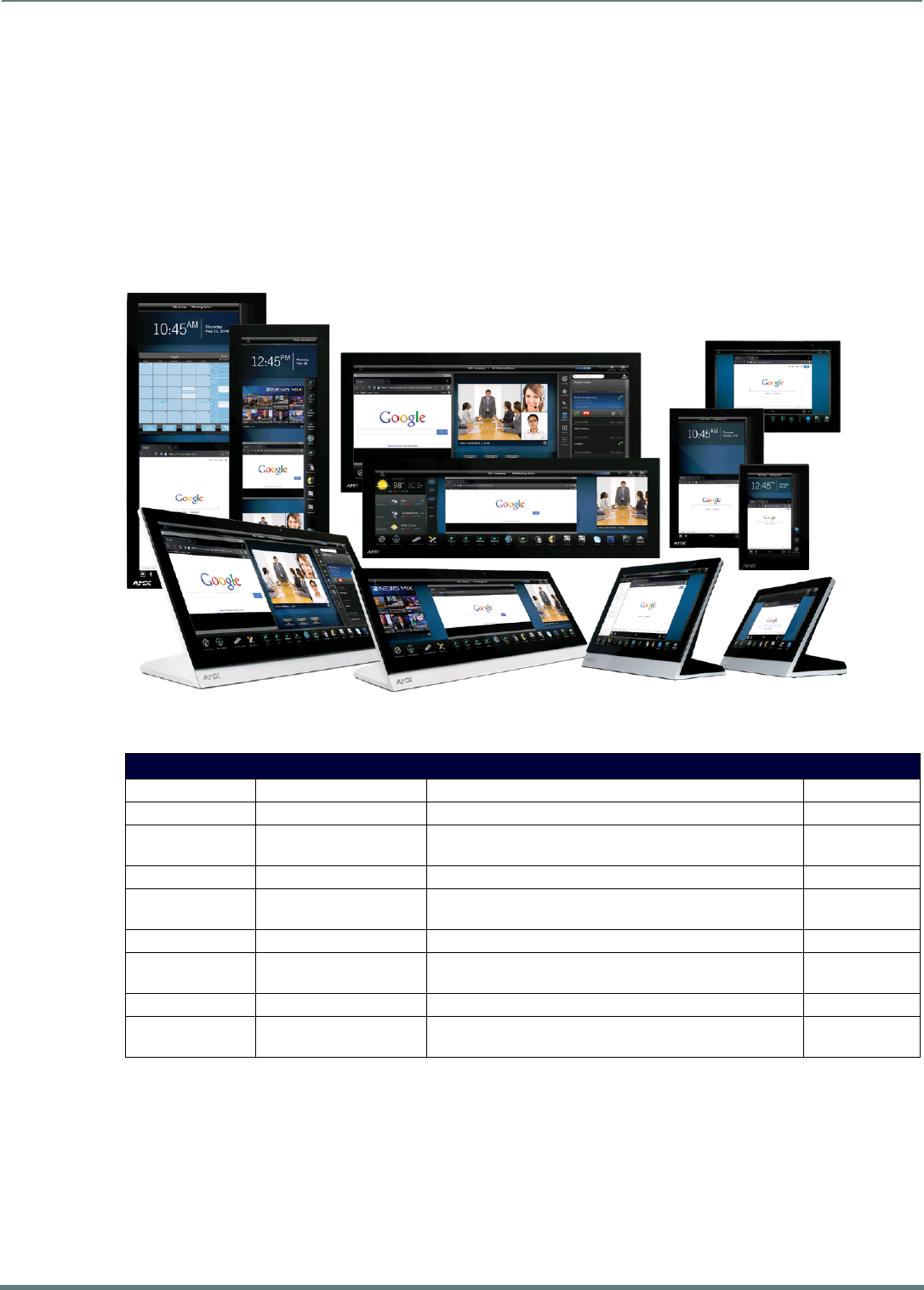
The Modero X Series G5 Touch Panels covered in this manual include:
NOTE: Note: The X Series G5 panels described in this document represent a different product family than the X Series (G4) touch
panels. For information on X Series G4 touch panels, refer to the Modero X Series G4 Touch Panels Instruction Manual.
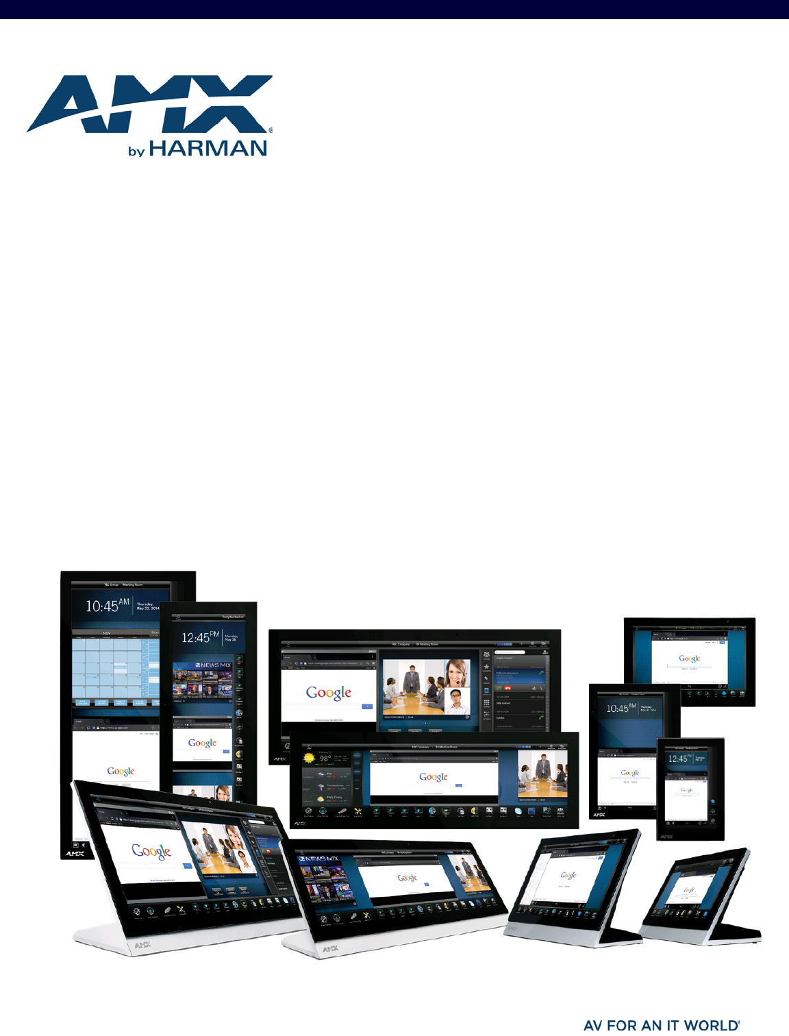
FIG. 1 Modero X Series G5 Touch Panels
Modero X Series G5 Touch Panels
Name FG# Description Page Ref
MXT-2001-PAN FG5968-35 20.3" Modero X Series G5 Panoramic Tabletop page 11
MXD-2001-PAN-P
MXD-2001-PAN-L
Portrait: FG5968-36
Landscape: FG5968-37
20.3" Modero X Series G5 Panoramic Wall-Mounts page 13
MXT-1901-PAN FG5968-41 19.4" Modero X Series G5 Panoramic Tabletop page 16
MXD-1901-PAN-P
MXD-1901-PAN-L
Portrait: FG5968-42
Landscape: FG5968-43
19.4" Modero X Series G5 Panoramic Wall-Mounts page 18
MXT-1001 FG5968-47 10.1" Modero X Series G5 Tabletop page 21
MXD-1001-P
MXD-1001-L
Portrait: FG5968-48
Landscape: FG5968-49
10.1" Modero X Series G5 Wall-Mounts page 23
MXT-701 FG5968-53 7" Modero X Series G5 Tabletop page 26
MXD-701-P
MXD-701-L
Portrait: FG5968-54
Landscape: FG5968-55
7" Modero X Series G5 Wall-Mounts page 28
Modero X Series G5 Touch Panels
8
Modero X® Series G5 Touch Panels - installation & Hardware Reference Manual
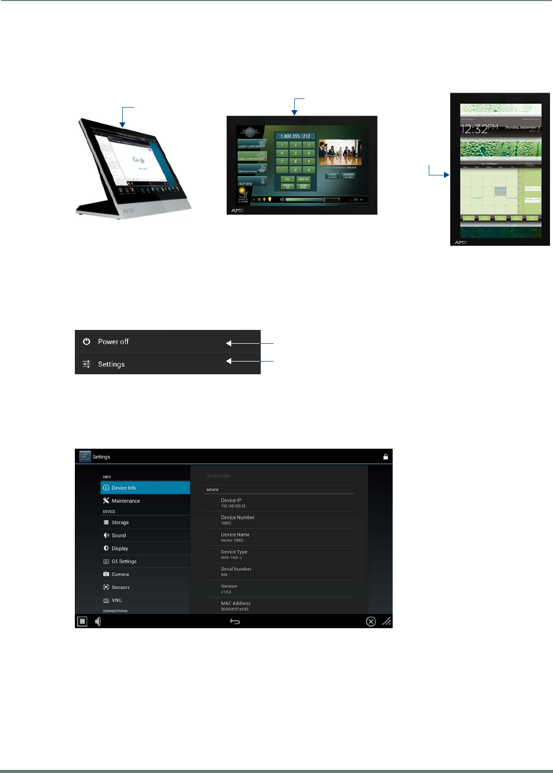
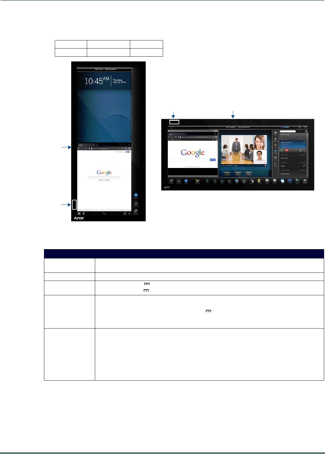
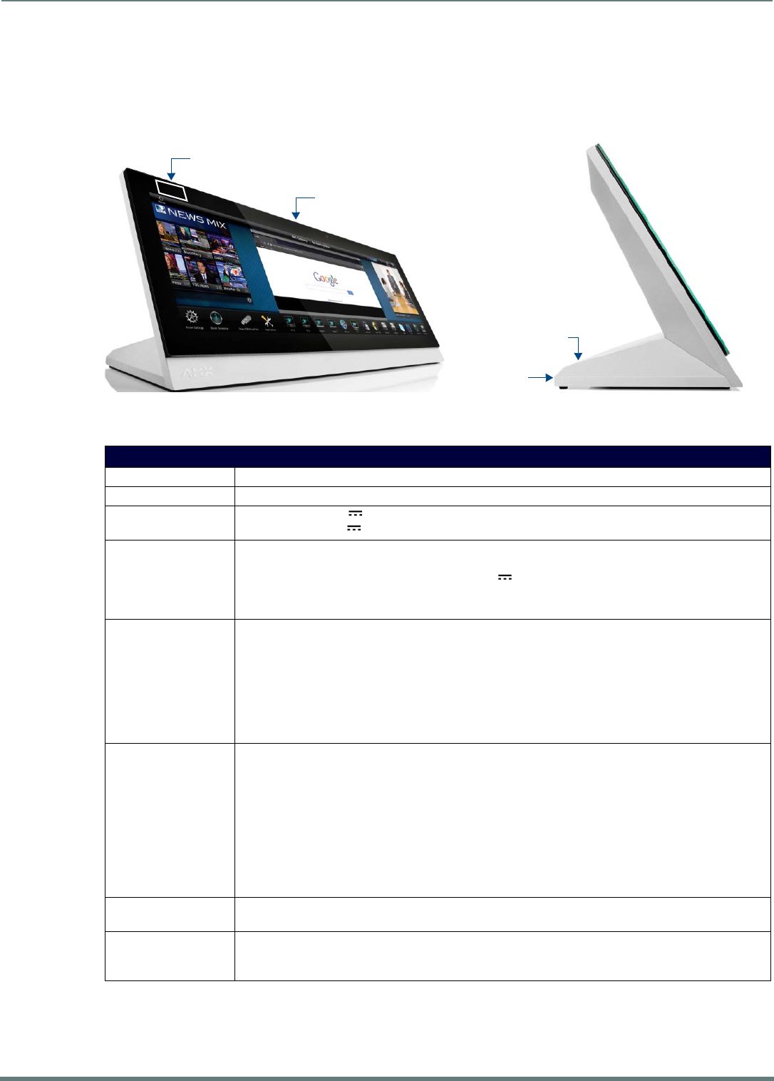
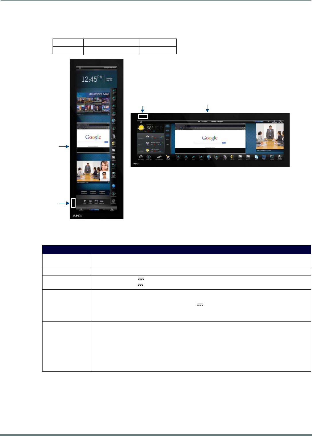
Sleep Button
X Series G5 touch panels are operated using its integral touchscreen, as well as the Sleep button. The Sleep button is located in the
in the center of the top panel of the device for tabletop and landscape wall-mount panels; it is located in the center of the left panel
for portrait panels (see FIG. 2 on page 8).
If the device has gone into its Sleep Mode, touching the touchscreen or pressing the Sleep button will reactivate it. Press and hold
the Sleep button to access the Settings menu.
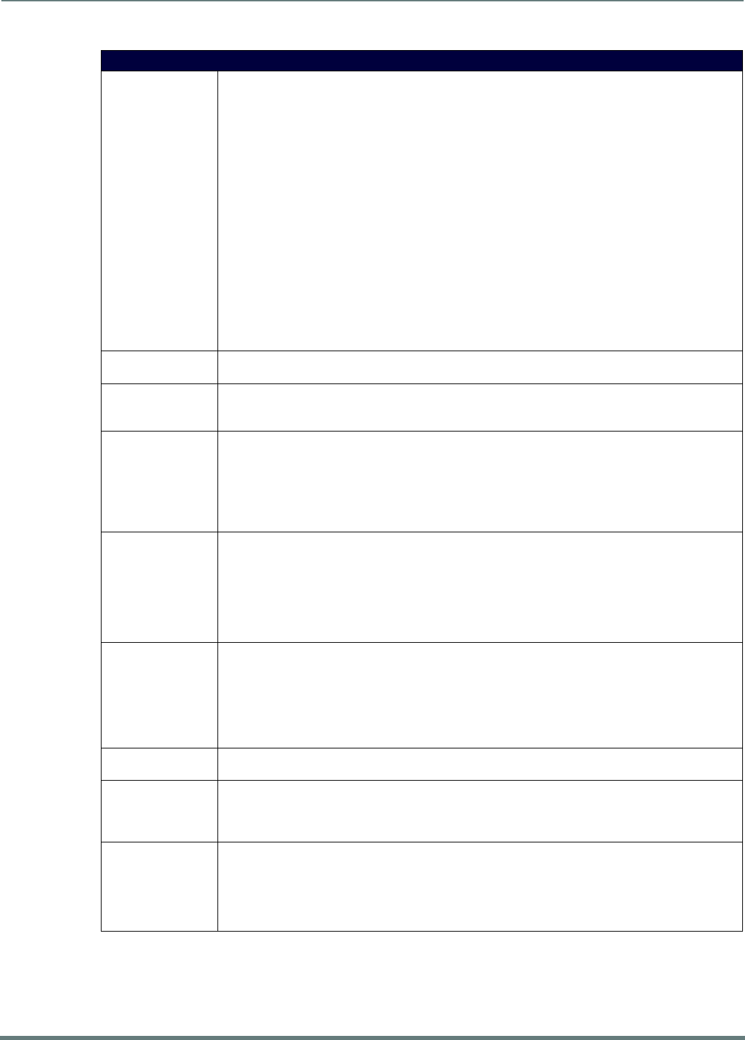
Powering On/Off X Series G5 Panels
Modero X Series G5 touch panels may be powered on by touching the Sleep button. To power off the panel, press and hold the
Sleep button, and select Power Off on the on-screen menu (FIG. 3):
Conf iguration and Programming
X Series G5 touch panels are equipped with a Settings menu that provides the ability to configure various features on the panels. To
access the Settings menu, press and hold the Sleep button, and select Settings (FIG. 3). This opens the main Settings menu
(FIG. 4):
Information on the Settings menu, panel configuration, and programming is included in the Modero X Series G5 Programming
Guide, available at www.amx.com.
NOTE: Note: Programming the Modero X Series G5 touch panels require the use of the latest versions of NetLinx Studio and
TPDesign5, both available to download at www.amx.com.
Bluetooth Support
X Series G5 touch panels allow the use of Bluetooth keyboard and mouse combinations, using HID Profile v1.1. Using a keyboard
and mouse with the device requires use of the MXA-BT Bluetooth USB Adapter (FG5968-19).
FIG. 2 Sleep Button location - Tabletop, Landscape and Portrait layouts)
FIG. 3 Sleep Button - Press to power on the panel; press and hold to access Power Off/Settings options
FIG. 4 Main Settings menu
Sleep button
Sleep button
(on top panel)
(on top panel)
Sleep button
(on left panel)
Press to power of the panel
Press to access the Settings menu
Modero X Series G5 Touch Panels
9
Modero X® Series G5 Touch Panels - installation & Hardware Reference Manual
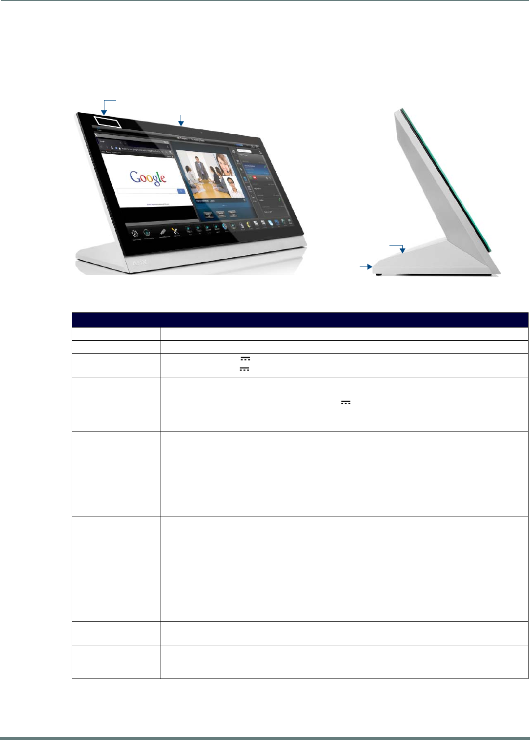
NFC Support
X Series G5 touch panels support Near Field Communications™ (NFC) Technology. NFC technology facilitates making transactions,
exchanging digital content, and connecting electronic devices with a touch. NFC transmissions are short-range (from a touch to a
few centimeters), working with existing contact-less card technologies and containing built-in capabilities to support secure
applications. By using NFC technology, users may receive access to touch panels and touch panel pages through access badges
and other card options.
The maximum range for the NFC antenna is 0.5" (12.7mm), but the typical usage range is 0.25" (6.35mm).
The antenna itself is accessible from the front of the panel, 3.25" (82.55mm) from the left corner of the panel and 0.375"
(9.53mm) from the top edge.
When using an NFC device with the X Series G5 panels, align your device’s antenna with the center of the touch panel’s antenna
(FIG. 5):
Active Video Windows - Limitations
The following limitations apply to the display of active video windows on X Series G5 panels:
NOTE: The term "Active Video Windows" refers to any "window" on the touch panel (which could be a Page, Popup, Sub-Page or
Button) that is displaying active video content.
Maximum supported number of active video windows displayed simultaneously on the panel: 2
While this limitation is not enforced (i.e the TPDesign5 application will allow you include any number of video windows in
the panel design), attempting to display more than two active video windows at one time may have a negative impact on
the panel’s overall performance.
Maximum supported resolution for video windows: 720dpi
Maximum supported frame rate for video windows: 30fps
Cleaning the Touch Overlay and Case
X Series G5 touch panels come with the MXA-CLK Modero X Series Cleaning Kit (FG5968-16), which may be used to clean
fingerprints and dirt from the device. This kit comes with cleaning cloths and a bottle of cleaning fluid specifically for use with the
device.
When cleaning the device, do not directly spray the device with cleaning fluid. Instead, spray the cloth and then apply the
cloth to the touch screen.
Do NOT use abrasives of any type to clean the device, as abrasives may permanently damage or remove the device’s finish.
Common Access Card (CAC) Support In MXT/D-2000XL-PAN
Card Type Card Unique Identif ier (UID) Card Data Personal Identity Verif ication (PIV) Card holder UID
15693 8 byte UID Not Supported N/A
14443A Non-Gov't 4, 7 or 10 byte UID (1) Not Supported N/A
14443A Gov't 4, 7 or 10 byte UID (1) Not Supported (2) Not currently
14443B Non-Gov't 4 byte UID Not Supported N/A
14443B Gov't 4 byte UID Not Supported (2) Not currently
FeliCa Not Supported Not Supported N/A
(1) The UID can be a fixed unique number or a random number dynamically generated by the card.
(2) Requires contact card reader (not accessible via NFC)
FIG. 5 NFC antenna location (Tabletop, Landscape and Portrait layouts)
NFC Sensor
NFC Sensor
NFC Sensor

Modero X Series G5 Touch Panels
10
Modero X® Series G5 Touch Panels - installation & Hardware Reference Manual
Additional Documentation
Refer to the Modero X Series G5 Touch Panels Configuration and Programming Manual for details on configuring and programming
G5 touch panels, including:
Information on Modero X Series G5 Programming, including Transitioning from G4 to G5
Detailed descriptions of each page and page option available in the G5 Settings Menu
Firmware upgrades via the G5 Settings Menu (Reset and Update page)
Using Content Sharing
Using Gestures
MXA-MP and MXA-MPL Programming
Detailed descriptions of all G5-supported Send Commands and SSH Commands
NOTE: Refer to the Modero G5 Conf iguration and Programming - X Series G5 Touch Panels Instruction Manual for details.
NOTE: Touch Panel f iles for G5 Touch Panels are created via TPDesign5 software (available to download from www.amx.com). Refer to
the TPDesign5 online help and Instruction Manual for details.
MXT/D-2001-PAN - 20.3" X Series G5 Panels
11
Modero X® Series G5 Touch Panels - installation & Hardware Reference Manual
MXT/D-2001-PAN - 20.3" X Series G5 Panels
MXT-2001-PAN (Tabletop)
MXT-2001-PAN Specif ications
FIG. 6 MXT-2001-PAN touch panel
MXT-2001-PAN Specif ications
DIMENSIONS (HWD) 9 3/16" x 20 3/8" x 5 7/8" (235mm x 519mm x 150mm)
WEIGHT 12.3 lbs (5.58 Kg)
POWER CONSUMPTION • Full-On: 35 W (13.5V , 2.6A)
• Standby: 7 W (13.5V , 0.52A)
EXTERNAL POWER
SUPPLY REQUIRED
Requires one of these AMX power sources (not included):
• PSR4.4 Power Supply, 4.5A, 3.5mm Phoenix with Retention Screws (FG423-46)
• PSN4.4 Power Supply, 4.5A, 3.5mm Phoenix, 13.5V (discontinued) (FG423-45)
• MXA-MPL Modero X/S Series Multi Preview Live (FG5968-10)
• MXA-MP Modero X/S Series Multi Preview (FG5968-20)
CERTIFICATIONS • FCC Part 15 Class B
• C-Tick CISPR 22 Class B
• CE EN 55022 Class B and EN 55024
• CB Scheme IEC 60950-1
•IC
• IEC/EN-60950
•UL 60950-1
•RoHS/WEEE compliant
TOUCH SCREEN DISPLAY • Display Type: TFT Active Matrix Color LCD with In-plane Switching Technology (IPS)
• Display Size (WH): 20.4" x 9.5" (519mm x 242mm), 21.3" (541mm) diagonal
• Viewable Area (WH): 18.7" x 7.8" (475mm x 198mm ), 20.3" (514mm) diagonal
• Resolution: 1920x800
• Aspect Ratio: 12:5
• Brightness: 250 cd/m2
• Contrast Ratio: 1000:1
• Color Depth: 16.7M colors
• Illumination: LED
• Touch Overlay: Projected capacitive, multi-touch support, 3 simultaneous max
VIEWING ANGLE • Vertical: ± 89°
• Horizontal: ± 89°
MEMORY • SDRAM: 2 GB
•Flash: 16 GB
• Maximum Project Size: 12 GB flash, available for apps and touch panel files
Sleep Button
NFC Sensor
USB Ports (2)
Cable Slot

MXT/D-2001-PAN - 20.3" X Series G5 Panels
12
Modero X® Series G5 Touch Panels - installation & Hardware Reference Manual
MXT-2001-PAN Specif ications (Cont.)
COMMUNICATIONS • Ethernet: 10/100 Auto MDI-X port, RJ-45 connector. Supported IP and IP-Based Protocols: UCP, TCP, ICMP,
ICSP, IGMP, DHCP, SSH, FTP, DNS, RFB (for VNC), HTTP
• USB: (3) USB host 2.0, Type A ports: Firmware upgrade, Touch Panel File Transfer, document and image
viewing, HID Peripherals
• Near Field Communication (NFC): Supports standards ISO/IEC 15693, ISO/IEC 14443A, ISO/IEC 14443B;
Unique Identifier (UID), typ range=.25", max = .5"
• Bluetooth: Mouse/Keyboard: HID Profile v1.1, requires MXA-BT Bluetooth Adapter (FG5968-19)
VIDEO • Supported Video Codecs:
MPEG2-TS: MPEG-2 Main Profile @High Level up to 720p at 25 fps (decode only)
MPEG-2-TS: H.264 High Profile @Layer 4, AAC-LC up to 720p at 25 fps (encode/decode)
MJPEG up to 720p at 25 fps (decode only)
• Supported Video Transport Streams: MPEG-TS for MPEG-2 and H.264, HTTP for MJPEG
• Max Number of Active Video Streams: 2 (720dpi/30fps)
• Video Conferencing: Panel-to-panel and video chat*
AUDIO • Microphone: -42 dB ±3 dB sensitivity FET microphone
• Speakers: 4 ohm, 2 Watt, 300 Hz cutoff frequency
• Supported Audio Codecs: MP2 Layer I and II, MP3 (8 kHz, 11.025 kHz, 12 kHz, 16 kHz, 22.05 kHz, 24 kHz,
32 kHz, 44.1 kHz, 48 kHz), AAC-LC (8 kHz, 96 kHz), G.711 with μLaw (VoIP* encode/decode at 8 kHz)
Suggested max packet size for G.711 Voice: 20ms
• File Formats: WAV, MP3 (as part of touch panel file only - no USB storage)
•Intercom*: Full Duplex VoIP, SIP v2.0
GRAPHICS ENGINE AMX G5: G5 enhanced feature set supporting multi-touch and gestures, scrolling, transitions, applications -
See TPD5 Operations Guide for more information
EMBEDDED
APPLICATIONS
• Viewer Applications*: PDF, JPEG, BMP, PNG, TIFF, GIF
• Remote Management: VNC Server
• Video Conferencing: Skype
• Audio Conferencing: Audio (Full Duplex Intercom*)
FRONT PANEL
COMPONENTS
• Light Sensor: Photosensitive light detector for automatic adjustment of the panel brightness
• Proximity Detector: Max range = ~3', typ range = ~1', FOV = ~10 degrees
• Camera: HD 720p camera for video conferencing/video chat support
• LED Indicators: Camera active indicator
• Sleep Button: Sleep button to activate sleep mode and powering off. Also provides access to setup pages
(can be disabled)
CONNECTIONS • Ethernet: 10/100 port, RJ-45 connector
•USB:
(3) USB host 2.0, Type A ports: Firmware upgrade, Touch Panel File Transfer, document and Image viewing
(1) Micro-USB device port (currently not in use)
• Power: 2-pin, locking 3.5mm Phoenix connector
ENVIRONMENTAL • Temperature (Operating): 32°F to 104°F (0°C to 40°C)
• Temperature (Storage): 4°F to 140°F (-20°C to 60°C)
• Humidity (Operating): 20% to 85% RH
• Humidity (Storage): 5% to 85% RH
• Power ("Heat") Dissipation:
On: 119.4 BTU/hr
Standby: 23.9 BTU/hr
INCLUDED
ACCESSORIES
• Locking 2-pin Phoenix mate (41-0002-SA)
• MXA-USB-C, USB Port Cover Kit, Modero X/S Series Touch Panel (FG5968-18)
• HPG-10-10K, 3/4" Mini-Grommet (FG570-01)
• MXA-CLK, Modero X/S Series Cleaning Kit (FG5968-16)
OPTIONAL
ACCESSORIES
• MXA-STMK-20, Secure Table Mount Kit, 20.3" Modero X Tabletop (FG5968-64)
• PSR4.4 Power Supply, 4.5A, 3.5mm Phoenix with Retention Screws (FG423-46)
• PSN4.4 Power Supply, 4.5A, 3.5mm Phoenix, 13.5V (discontinued) (FG423-45)
• MXA-MPL Modero X/S Series Multi Preview Live (FG5968-10)
• MXA-MP Modero X/S Series Multi Preview (FG5968-20)
• HPG-10-10K, 3/4" Mini-Grommet, 10-Pack (FG570-01-10K)
• MXA-BT, Bluetooth USB Adapter for Modero X/S Series (FG5968-19)
• MXA-CLK, Modero X/S Series Cleaning Kit (FG5968-16)
• MXA-USB-C, USB Port Covers for the Modero X/S Series Touch Panels (FG5968-18)
* This feature will be available upon release of a future firmware update.
MXT/D-2001-PAN - 20.3" X Series G5 Panels
13
Modero X® Series G5 Touch Panels - installation & Hardware Reference Manual
MXD-2001-PAN (Wall-Mount - Landscape/Portrait)
The MXD-2001-PAN is available in Portrait and Landscape layouts:
MXD-2001-PAN Specif ications
Portrait MXD-2001-PAN-P FG5968-36
Landscape MXD-2001-PAN-L FG5968-37
FIG. 7 MXD-2001-PAN-P/L (Portrait and Landscape)
MXD-2001-PAN Specifications
DIMENSIONS (HWD) • Landscape: 9 1/2" x 20 3/8" x 11/16" (242mm x 519mm x 19mm)
• Portrait: 20 3/8" x 9 1/2" x 11/16" (519mm x 242mm x 19mm
WEIGHT 9.0 lbs (4.08 Kg)
POWER CONSUMPTION • Full-On: 35 W (13.5V , 2.6A)
• Standby: 7 W (13.5V , 0.52A)
EXTERNAL POWER
SUPPLY REQUIRED
Requires one of these AMX power sources (not included):
• PSR4.4 Power Supply, 4.5A, 3.5mm Phoenix with Retention Screws (FG423-46)
• PSN4.4 Power Supply, 4.5A, 3.5mm Phoenix, 13.5V (discontinued) (FG423-45)
• MXA-MPL Modero X/S Series Multi Preview Live (FG5968-10)
• MXA-MP Modero X/S Series Multi Preview (FG5968-20)
CERTIFICATIONS • FCC Part 15 Class B
• C-Tick CISPR 22 Class B
• CE EN 55022 Class B and EN 55024
• CB Scheme IEC 60950-1
•IC
• IEC/EN-60950
•UL 60950-1
•RoHS/WEEE compliant
Sleep ButtonNFC Sensor
Sleep
NFC
Button
Sensor
MXD-2001-PAN-P
MXD-2001-PAN-L
MXT/D-2001-PAN - 20.3" X Series G5 Panels
14
Modero X® Series G5 Touch Panels - installation & Hardware Reference Manual
MXD-2001-PAN Specifications (Cont.)
TOUCH SCREEN
DISPLAY
• Display Type: TFT Active Matrix Color LCD with In-plane Switching Technology (IPS)
•Display Size (WH)
Landscape: 20.4" x 9.5" (519mm x 242mm), 21.3" (541mm) diagonal
Portrait: 9.5" x 20.4" (242mm x 519mm), 21.3" (541mm) diagonal
• Viewable Area (WH)
Landscape 18.7" x 7.8" (475mm x 198mm ), 20.3" (514mm) diagonal
Portrait 7.8" x 18.7" (198mm x 475mm), 20.3" (514mm) diagonal
•Resolution
Landscape: 1920x800
Portrait: 800x1920
• Aspect Ratio
Landscape: 12:5
Portrait: 5:12
• Brightness: 250 cd/m2
• Contrast Ratio: 1000:1
• Color Depth: 16.7M colors
• Illumination: LED
• Touch Overlay: Projected capacitive, multi-touch support, 3 simultaneous max
VIEWING ANGLE • Vertical: ± 89°
• Horizontal: ± 89°
MEMORY • SDRAM: 2 GB
•Flash: 16 GB
• Maximum Project Size: 12 GB flash, available for apps and touch panel files
COMMUNICATIONS • Ethernet: 10/100 Auto MDI-X port, RJ-45 connector. Supported IP and IP-Based Protocols: UCP, TCP, ICMP,
ICSP, IGMP, DHCP, SSH, FTP, DNS, RFB (for VNC), HTTP
• USB: (2) USB host 2.0, Type A ports (1 with limited physical access requiring right angle connection):
Firmware upgrade, Touch Panel File Transfer, document and image viewing, HID Peripherals
• Near Field Communication (NFC): Supports standards ISO/IEC 15693, ISO/IEC 14443A, ISO/IEC 14443B;
Unique Identifier (UID), typ range=.25", max = .5"
• Bluetooth: Mouse/Keyboard: HID Profile v1.1, requires MXA-BT Bluetooth Adapter (FG5968-19)
VIDEO • Supported Video Codecs:
MPEG-2-TS: MPEG-2 Main Profile@High Level up to 720p at 25 fps (decode only)
MPEG-2-TS: H.264 High Profile@Layer 4, AAC-LC up to 720p at 25 fps (encode/decode)
MJPEG up to 720p at 25 fps (decode only)
• Supported Video Transport Streams: MPEG-TS for MPEG2 and H.264; HTTP for MJPEG
• Max Number of Active Video Streams: 2 (720dpi/30fps)
• Video Conferencing: Panel-to-panel and video chat*
AUDIO • Microphone: -42 dB ±3 dB sensitivity FET microphone
• Speakers: 4 ohm, 2 Watt, 300 Hz cutoff frequency
• Supported Audio Codecs: MP2 Layer I and II, MP3 (8 kHz, 11.025 kHz, 12 kHz, 16 kHz, 22.05 kHz, 24 kHz,
32 kHz, 44.1 kHz, 48 kHz), AAC-LC (8 kHz, 96 kHz), G.711 with μLaw (VoIP* encode/decode at 8 kHz)
Suggested max packet size for G.711 Voice: 20ms
• File Formats: WAV, MP3 (as part of touch panel file only - no USB storage)
•Intercom*: Full Duplex VoIP, SIP v2.0
GRAPHICS ENGINE AMX G5: G5 enhanced feature set supporting multi-touch and gestures, scrolling, transitions, applications - See
TPD5 Operations Guide for more information
EMBEDDED
APPLICATIONS
• Viewer Applications*: PDF, JPEG, BMP, PNG, TIFF, GIF
• Remote Management: VNC Server
• Video Conferencing: Skype
• Audio Conferencing: Audio (Full Duplex Intercom*)
FRONT PANEL
COMPONENTS
• Light Sensor: Photosensitive light detector for automatic adjustment of the panel brightness
• Proximity Detector: Max range = ~3', typ range = ~1', FOV = ~10 degrees
• Camera: HD 720p camera for video conferencing/video chat support
• LED Indicators: Camera active indicator
• Sleep Button: Sleep button to activate sleep mode and powering off. Also provides access to setup pages (can
be disabled)
MXT/D-2001-PAN - 20.3" X Series G5 Panels
15
Modero X® Series G5 Touch Panels - installation & Hardware Reference Manual
MXD-2001-PAN Specifications (Cont.)
CONNECTIONS • Ethernet: 10/100 port, RJ-45 connector
•USB:
(2) USB host 2.0, Type A ports
(1) Micro-USB device port (currently not in use)
• Power: 2-pin, locking 3.5mm Phoenix connector
ENVIRONMENTAL • Temperature (Operating): 32°F to 104°F (0°C to 40°C)
• Temperature (Storage): 4°F to 140°F (-20°C to 60°C)
• Humidity (Operating): 20% to 85% RH
• Humidity (Storage): 5% to 85% RH
• Power ("Heat") Dissipation:
• On: 119.4 BTU/hr
• Standby: 23.9 BTU/hr
INCLUDED
ACCESSORIES
• Locking 2-pin Phoenix mate (41-0002-SA)
• MXA-USB-C, USB Port Cover Kit, Modero X Series Touch Panel (FG5968-18)
• MXA-CLK, Modero X Series Cleaning Kit (FG5968-16)
• Installation Template 20.3" (68-5968-01)
OPTIONAL
ACCESSORIES
• MXA-RMK-20 Modero X Series Rack Mount Kit (FG5969-60)
• MXA-FMK-20 Flush Mount Kit for 20.3" Modero X Series Wall Mount Touch Panels (FG5968-68)
• PSR4.4 Power Supply, 4.5A, 3.5mm Phoenix with Retention Screws (FG423-46)
• PSN4.4 Power Supply, 4.5A, 3.5mm Phoenix, 13.5V (discontinued) (FG423-45)
• MXA-MPL Modero X/S Series Multi Preview Live (FG5968-10)
• MXA-MP Modero X/S Series Multi Preview (FG5968-20)
• CB-MXP19/20, Rough-In Box (FG039-15)
• MXA-BT, Bluetooth USB Adapter for Modero X/S Series (FG5968-19)
• MXA-CLK, Modero X/S Series Cleaning Kit (FG5968-16)
• MXA-USB-C, USB Port Covers for the Modero X Series Touch Panels (FG5968-18)
* This feature will be available upon release of a future firmware update.
MXT/D-1901-PAN - 19.4" X Series G5 Panels
16
Modero X® Series G5 Touch Panels - installation & Hardware Reference Manual
MXT/D-1901-PAN - 19.4" X Series G5 Panels
MXT-1901-PAN (Tabletop)
MXT-1901-PAN Specif ications
FIG. 8 MXT-1901-PAN touch panel
MXT-1901-PAN Specifications
DIMENSIONS (HWD) 7" x 20 3/8" x 5 5/16" (177mm x 519mm x 135mm)
WEIGHT 9.5 lbs (4.31 Kg)
POWER CONSUMPTION • Full-On: 35W (13.5V , 2.6A)
• Standby: 7W (13.5V , 0.52A)
EXTERNAL POWER
SUPPLY REQUIRED
Requires one of these AMX power sources (not included):
• PSR4.4 Power Supply, 4.5A, 3.5mm Phoenix with Retention Screws (FG423-46)
• PSN4.4 Power Supply, 4.5A, 3.5mm Phoenix, 13.5V (discontinued) (FG423-45)
• MXA-MPL Modero X/S Series Multi Preview Live (FG5968-10)
• MXA-MP Modero X/S Series Multi Preview (FG5968-20)
CERTIFICATIONS • FCC Part 15 Class B
• C-Tick CISPR 22 Class B
• CE EN 55022 Class B and EN 55024
• CB Scheme IEC 60950-1
•IC
• IEC/EN-60950
•UL 60950-1
•RoHS/WEEE compliant
TOUCH SCREEN DISPLAY • Display Type: TFT Active Matrix Color LCD with In-plane Switching Technology (IPS)
• Display Size (WH): Landscape 20.4" x 6.9" (519mm x 175mm), 20.4" (518mm) diagonal
• Viewable Area (WH): Landscape 18.7" x 5.9" (475mm x 151mm), 19.4" (493mm) diagonal
• Resolution: Landscape 1920x530
• Aspect Ratio: Landscape 18:5
• Brightness: 350 cd/m2
• Contrast Ratio: 1000:1
• Color Depth: 16.7M colors
• Illumination: LED
• Touch Overlay: Projected capacitive, multi-touch support, 3 simultaneous max
VIEWING ANGLE • Vertical: ± 89°
• Horizontal: ± 89°
MEMORY • SDRAM: 2 GB
•Flash: 16 GB
• Maximum Project Size: 12 GB flash, available for apps and touch panel files
Sleep Button
NFC Sensor
USB Ports (2)
Cable Slot

MXT/D-1901-PAN - 19.4" X Series G5 Panels
17
Modero X® Series G5 Touch Panels - installation & Hardware Reference Manual
MXT-1901-PAN Specifications (Cont.)
COMMUNICATIONS • Ethernet: 10/100 Auto MDI-X port, RJ-45 connector. Supported IP and IP-Based Protocols: UCP, TCP, ICMP,
ICSP, IGMP, DHCP, SSH, FTP, DNS, RFB (for VNC), HTTP
• USB: USB: (3) USB host 2.0, Type A ports: Firmware upgrade, Touch Panel File Transfer, document and
image viewing, HID Peripherals
• Near Field Communication (NFC): Supports standards ISO/IEC 15693, ISO/IEC 14443A, ISO/IEC 14443B;
Unique Identifier (UID), typ range=.25", max = .5"
• Bluetooth: Mouse/Keyboard: HID Profile v1.1, requires MXA-BT Bluetooth Adapter (FG5968-19)
VIDEO • Supported Video Codecs:
MPEG2-TS: MPEG-2 Main Profile @High Level up to 720p at 25 fps (decode only)
MPEG-2-TS: H.264 High Profile @Layer 4, AAC-LC up to 720p at 25 fps (encode/decode)
MJPEG up to 720p at 25 fps (decode only)
• Supported Video Transport Streams: MPEG-TS for MPEG-2 and H.264, HTTP for MJPEG
• Max Number of Active Video Streams: 2 (720dpi/30fps)
• Video Conferencing: Panel-to-panel and video chat*
AUDIO • Microphone: -42 dB ±3 dB sensitivity FET microphone
• Speakers: 4 ohm, 2 Watt, 300 Hz cutoff frequency
• Supported Audio Codecs: MP2 Layer I and II, MP3 (8 kHz, 11.025 kHz, 12 kHz, 16 kHz, 22.05 kHz, 24 kHz,
32 kHz, 44.1 kHz, 48 kHz), AAC-LC (8 kHz, 96 kHz), G.711 with μLaw (VoIP* encode/decode at 8 kHz)
Suggested max packet size for G.711 Voice: 20ms
• File Formats: WAV, MP3 (as part of touch panel file only - no USB storage)
•Intercom*: Full Duplex VoIP, SIP v2.0
GRAPHICS ENGINE AMX G5: G5 enhanced feature set supporting multi-touch and gestures, scrolling, transitions, applications -
See TPD5 Operations Guide for more information
EMBEDDED
APPLICATIONS
• Viewer Applications*: PDF, JPEG, BMP, PNG, TIFF, GIF
• Remote Management: VNC Server
• Video Conferencing: Skype
• Conferencing: Audio (Full Duplex Intercom*)
FRONT PANEL
COMPONENTS
• Light Sensor: Photosensitive light detector for automatic adjustment of the panel brightness
• Proximity Detector: Max range = ~3', typ range = ~1', FOV = ~10 degrees
• Camera: HD 720p camera for video conferencing/video chat support
• LED Indicators: Camera active indicator
• Sleep Button: Sleep button to activate sleep mode and powering off. Also provides access to setup pages
(can be disabled)
CONNECTIONS • Ethernet: 10/100 port, RJ-45 connector
•USB:
(3) USB host 2.0, Type A ports
(1) Micro-USB device port (currently not in use)
• Power: 2-pin, locking 3.5mm Phoenix connector
ENVIRONMENTAL • Temperature (Operating): 32°F to 104°F (0°C to 40°C)
• Temperature (Storage): 4°F to 140°F (-20°C to 60°C)
• Humidity (Operating): 20% to 85% RH
• Humidity (Storage): 5% to 85% RH
• Power ("Heat") Dissipation:
On: 119.4 BTU/hr
Standby: 23.9 BTU/hr
INCLUDED
ACCESSORIES
• Locking 2-pin Phoenix mate (41-0002-SA)
• MXA-USB-C, USB Port Cover Kit, Modero X/S Series Touch Panel (FG5968-18)
• HPG-10-10K, 3/4" Mini-Grommet (FG570-01)
• MXA-CLK, Modero X/S Series Cleaning Kit (FG5968-16)
OPTIONAL
ACCESSORIES
• MXA-STMK-19, Secure Table Mount Kit, 19.4" Modero X Tabletop (FG5968-65)
• PSR4.4 Power Supply, 4.5A, 3.5mm Phoenix with Retention Screws (FG423-46)
• PSN4.4 Power Supply, 4.5A, 3.5mm Phoenix, 13.5V (discontinued) (FG423-45)
• MXA-MPL Modero X/S Series Multi Preview Live (FG5968-10)
• MXA-MP Modero X/S Series Multi Preview (FG5968-20)
• HPG-10-10K, 3/4" Mini-Grommet, 10-Pack (FG570-01-10K)
• MXA-BT, Bluetooth USB Adapter for Modero X/S Series (FG5968-19)
• MXA-CLK, Modero X/S Series Cleaning Kit (FG5968-16)
• MXA-USB-C, USB Port Covers for the Modero X/S Series Touch Panels (FG5968-18)
* This feature will be available upon release of a future firmware update.
MXT/D-1901-PAN - 19.4" X Series G5 Panels
18
Modero X® Series G5 Touch Panels - installation & Hardware Reference Manual
MXD-1901-PAN (Wall-Mount - Landscape/Portrait)
The MXD-1901-PAN is available in Portrait and Landscape layouts:
MXD-1901-PAN Specif ications
Portrait MXD-1901-PAN-P FG5968-42
Landscape MXD-1901-PAN-L FG5968-43
FIG. 9 MXD-1901-PAN (Portrait and Landscape)
MXD-1901-PAN Specifications
DIMENSIONS (HWD) • Landscape: 6 7/8" x 20 3/8" x 11/16" (175mm x 519mm x 19mm)
• Portrait: 20 3/8" x 6 7/8" x 11/16" (519mm x 175mm x 19mm)
WEIGHT 6.9 lbs (3.13 Kg)
POWER CONSUMPTION • Full-On: 35 W (13.5V , 2.6A)
• Standby: 7 W (13.5V , 0.52A)
EXTERNAL POWER
SUPPLY REQUIRED
Requires one of these AMX power sources (not included):
• PSR4.4 Power Supply, 4.5A, 3.5mm Phoenix with Retention Screws (FG423-46)
• PSN4.4 Power Supply, 4.5A, 3.5mm Phoenix, 13.5V (discontinued) (FG423-45)
• MXA-MPL Modero X/S Series Multi Preview Live (FG5968-10)
• MXA-MP Modero X/S Series Multi Preview (FG5968-20)
CERTIFICATIONS • FCC Part 15 Class B
• C-Tick CISPR 22 Class B
• CE EN 55022 Class B and EN 55024
• CB Scheme IEC 60950-1
•IC
• IEC/EN-60950
•UL 60950-1
•RoHS/WEEE compliant
Sleep Button
NFC Sensor
Sleep
NFC
Button
Sensor
MXD-1901-PAN-P
MXD-1901-PAN-L

MXT/D-1901-PAN - 19.4" X Series G5 Panels
19
Modero X® Series G5 Touch Panels - installation & Hardware Reference Manual
MXD-1901-PAN Specif ications (Cont.)
TOUCH SCREEN
DISPLAY
• Display Type: TFT Active Matrix Color LCD with In-plane Switching Technology (IPS)
•Display Size (WH)
Landscape: 20.4" x 6.9" (519mm x 175mm), 20.4" (518mm) diagonal
Portrait: 6.9" x 20.4" (175mm x 519mm), 20.4" (518mm) diagonal
• Viewable Area (WH)
Landscape: 18.7" x 5.9" (475mm x 151mm), 19.4" (493mm) diagonal
Portrait: 5.9" x 18.7" (151mm x 475mm), 19.4" (493mm) diagonal
•Resolution
Landscape: 1920x530
Portrait: 530x1920
• Aspect Ratio
Landscape: 18:5
Portrait: 5:18
• Brightness: 350 cd/m2
• Contrast Ratio: 1000:1
• Color Depth: 16.7M colors
• Illumination: LED
• Touch Overlay: Projected capacitive, multi-touch support, 3 simultaneous max
VIEWING ANGLE • Vertical: ± 89°
• Horizontal: ± 89°
MEMORY • SDRAM: 2 GB
•Flash: 16 GB
• Maximum Project Size: 12 GB flash, available for apps and touch panel files
COMMUNICATIONS • Ethernet: 10/100 Auto MDI-X port, RJ-45 connector. Supported IP and IP-Based Protocols: UCP, TCP, ICMP,
ICSP, IGMP, DHCP, SSH, FTP, DNS, RFB (for VNC), HTTP
• USB: (2) USB host 2.0, Type A ports (1 with limited physical access requiring right angle connection):
Firmware upgrade, Touch Panel File Transfer, document and image viewing, HID Peripherals
• Near Field Communication (NFC): Supports standards ISO/IEC 15693, ISO/IEC 14443A, ISO/IEC 14443B;
Unique Identifier (UID), typ range=.25", max = .5"
• Bluetooth: Mouse/Keyboard: HID Profile v1.1, requires MXA-BT Bluetooth Adapter (FG5968-19)
VIDEO • Supported Video Codecs:
MPEG-2-TS: MPEG-2 Main Profile@High Level up to 720p at 25 fps (decode only)
MPEG-2-TS: H.264 High Profile@Layer 4, AAC-LC up to 720p at 25 fps (encode/decode)
MJPEG up to 720p at 25 fps (decode only)
• Supported Video Transport Streams: MPEG-TS for MPEG2 and H.264; HTTP for MJPEG
• Max Number of Active Video Streams: 2 (720dpi/30fps)
• Video Conferencing: Panel-to-panel and video chat*
• Video Output: Camera video output: H.264, up to 720p@25 fps via Micro-USB port only (controlled by host
device)
AUDIO • Microphone: -42 dB ±3 dB sensitivity FET microphone
• Speakers: 4 ohm, 2 Watt, 300 Hz cutoff frequency
• Supported Audio Codecs: MP2 Layer I and II, MP3 (8 kHz, 11.025 kHz, 12 kHz, 16 kHz, 22.05 kHz, 24 kHz,
32 kHz, 44.1 kHz, 48 kHz), AAC-LC (8 kHz, 96 kHz), G.711 with μLaw (VoIP* encode/decode at 8 kHz)
Suggested max packet size for G.711 Voice: 20ms
• File Formats: WAV, MP3 (as part of touch panel file only - no USB storage)
• Intercom*: Full Duplex VoIP, SIP v2.0
GRAPHICS ENGINE AMX G5: G5 enhanced feature set supporting multi-touch and gestures, scrolling, transitions, applications - See
TPD5 Operations Guide for more information
EMBEDDED
APPLICATIONS
•Applications*: PDF, JPEG, BMP, PNG, TIFF, GIF
• Remote Management: VNC Server
• Video Conferencing: Skype
• Audio Conferencing: Audio (Full Duplex Intercom*)
FRONT PANEL
COMPONENTS
• Light Sensor: Photosensitive light detector for automatic adjustment of the panel brightness
• Proximity Detector: Max range = ~3', typ range = ~1', FOV = ~10 degrees
• Camera, Landscape Model Only (FG5968-43): HD 720p camera for video conferencing/video chat support
• LED Indicators: Camera active indicator (models with camera only)
• Sleep Button: Sleep button to activate sleep mode and powering off. Also provides access to setup pages (can
be disabled)
MXT/D-1901-PAN - 19.4" X Series G5 Panels
20
Modero X® Series G5 Touch Panels - installation & Hardware Reference Manual
MXD-1901-PAN Specif ications (Cont.)
CONNECTIONS • Ethernet: 10/100 port, RJ-45 connector
•USB:
(2) USB host 2.0, Type A ports
(1) Micro-USB device port (currently not in use)
• Power: 2-pin, locking 3.5mm Phoenix connector
ENVIRONMENTAL • Temperature (Operating): 32°F to 104°F (0°C to 40°C)
• Temperature (Storage): 4°F to 140°F (-20°C to 60°C)
• Humidity (Operating): 20% to 85% RH
• Humidity (Storage): 5% to 85% RH
• Power ("Heat") Dissipation:
On: 119.4 BTU/hr
Standby: 23.9 BTU/hr
INCLUDED
ACCESSORIES
• Locking 2-pin Phoenix mate (41-0002-SA)
• MXA-USB-C, USB Port Cover Kit, Modero X Series Touch Panel (FG5968-18)
• MXA-CLK, Modero X Series Cleaning Kit (FG5968-16)
• Installation Template 19.4" (68-5968-02)
OPTIONAL
ACCESSORIES
• MXA-FMK-19 Flush Mount Kit, 19.4" Modero X Wall Mount (FG5968-69)
• MXA-RMK-19 Modero X Series Rack Mount Kit (FG5969-61)
• PSR4.4 Power Supply, 4.5A, 3.5mm Phoenix with Retention Screws (FG423-46)
• PSN4.4 Power Supply, 4.5A, 3.5mm Phoenix, 13.5V (discontinued) (FG423-45)
• MXA-MPL Modero X/S Series Multi Preview Live (FG5968-10)
• MXA-MP Modero X/S Series Multi Preview (FG5968-20)
• CB-MXP19/20, Rough-In Box (FG039-15)
• MXA-BT, Bluetooth USB Adapter for Modero X/S Series (FG5968-19)
• MXA-CLK, Modero X/S Series Cleaning Kit (FG5968-16)
• MXA-USB-C, USB Port Covers for the Modero X Series Touch Panels (FG5968-18)
* This feature will be available upon release of a future firmware update.
MXT/D-1001 - 10.1" X Series G5 Panels
21
Modero X® Series G5 Touch Panels - installation & Hardware Reference Manual
MXT/D-1001 - 10.1" X Series G5 Panels
MXT-1001 (Tabletop)
MXT-1001 Specifications
FIG. 10 MXT-1001 Touch Panel
MXT-1001 Specifications
DIMENSIONS (HWD) 6 7/8" x 9 7/8" x 4 7/8" (174mm x 252mm x 124mm)
WEIGHT 3.1 lbs (1.41 Kg)
POWER CONSUMPTION • Full-On: 12.95W maximum
• Standby: 5.8W
• Shutdown: 1W
• Start-Up Inrush Current: Not applicable due to PoE standard
EXTERNAL POWER
SUPPLY REQUIRED
Optimal performance requires use of one of the following AMX PoE power supplies (not included):
• PS-POE-AF-TC, PoE Injector, 802.3AF Compliant (FG423-83)
• NXA-ENET8-2POE, Gigabit PoE Ethernet Switch (FG2178-63)
CERTIFICATIONS • UL 60950-1
• FCC Part 15 Class B
• C-Tick CISPR 22 Class B
• CE EN 55022 Class B and EN 55024
• CB Scheme IEC 60950-1
•IC
• IEC/EN-60950
•RoHS/WEEE compliant
TOUCH SCREEN
DISPLAY
• Display Type: TFT Active Matrix Color LCD with In-plane Switching Technology (IPS)
• Display Size (WH): 9.9" x 6.7" (252mm x 170mm), 12.0" (304mm) diagonal
• Viewable Area (WH): 8.5" x 5.3" (217mm x 136mm), 10.1" (257mm) diagonal
• Resolution (WH): 1280x800
• Aspect Ratio (WH): 16:9
• Brightness: 400 cd/m2
• Contrast Ratio: 700:1
• Color Depth: 16.7M colors
• Illumination: LED
• Touch Overlay: Projected capacitive, multi-touch support, 3 simultaneous max
VIEWING ANGLE • Vertical: ± 89°
• Horizontal: ± 89°
MEMORY • SDRAM: 2 GB
•Flash: 16 GB
• Maximum Project Size: 12 GB flash, available for apps and touch panel files
Sleep Button
NFC Sensor
USB Ports (2)

MXT/D-1001 - 10.1" X Series G5 Panels
22
Modero X® Series G5 Touch Panels - installation & Hardware Reference Manual
MXT-1001 Specifications (Cont.)
COMMUNICATIONS • Ethernet: 10/100 Auto MDI-X port, RJ-45 connector. Supported IP and IP-Based Protocols: UCP, TCP, ICMP,
ICSP, IGMP, DHCP, SSH, FTP, DNS, RFB (for VNC), HTTP
• USB: (2) USB host 2.0, Type A ports (1 with limited physical access requiring right angle connection):
Firmware upgrade, Touch Panel File Transfer, document and image viewing, HID Peripherals
• Near Field Communication (NFC): Supports standards ISO/IEC 15693, ISO/IEC 14443A, ISO/IEC 14443B;
Unique Identifier (UID), typ range=.25", max = .5"
•Bluetooth*:
Mouse/Keyboard: HID Profile v1.1, requires MXA-BT Bluetooth Adapter (FG5968-19)
Handset: Hands Free Profile v1.5, Headset Profile v1.2, requires MXA-BT Bluetooth Adapter (FG5968-19) and
MXA-HST Bluetooth Handset (FG5968-17)
VIDEO • Supported Video Codecs:
MPEG2-TS: MPEG-2 Main Profile @High Level up to 720p at 25 fps (decode only)
MPEG-2-TS: H.264 High Profile @Layer 4, AAC-LC up to 720p at 25 fps (encode/decode)
MJPEG up to 720p at 25 fps (decode only)
• Supported Video Transport Streams: MPEG-TS for MPEG-2 and H.264, HTTP for MJPEG
• Max Number of Active Video Streams: 2 (720dpi/30fps)
• Video Conferencing: Panel-to-panel and video chat*
AUDIO • Microphone: -42 dB ±3 dB sensitivity FET microphone
• Speakers: 4 ohm, 2 Watt, 300 Hz cutoff frequency
• Supported Audio Codecs: MP2 Layer I and II, MP3 (8 kHz, 11.025 kHz, 12 kHz, 16 kHz, 22.05 kHz, 24 kHz,
32 kHz, 44.1 kHz, 48 kHz), AAC-LC (8 kHz, 96 kHz), G.711 with μLaw (VoIP* encode/decode at 8 kHz)
Suggested max packet size for G.711 Voice: 20ms
• File Formats: WAV, MP3 (as part of touch panel file only - no USB storage)
•Intercom*: Full Duplex VoIP, SIP v2.0
GRAPHICS ENGINE AMX G5: G5 enhanced feature set supporting multi-touch and gestures, scrolling, transitions, applications - See
TPD5 Operations Guide for more information
EMBEDDED
APPLICATIONS
• Viewer Applications*: PDF, JPEG, BMP, PNG, TIFF, GIF
• Remote Management: VNC Server
• Video Conferencing: Skype
• Audio Conferencing: Audio (Full Duplex Intercom*)
FRONT PANEL
COMPONENTS
• Light Sensor: Photosensitive light detector for automatic adjustment of the panel brightness
• Proximity Detector: Max range = ~3', typ range = ~1', FOV = ~10 degrees
• Camera: HD 720p camera for video conferencing/video chat support
• LED Indicators: Camera active indicator
• Sleep Button: Sleep button to activate sleep mode and powering off. Also provides access to setup pages (can
be disabled)
CONNECTIONS • Ethernet: 10/100 port, RJ-45 connector through cable extension
•USB:
(2) USB host 2.0, Type A ports
(1) Micro-USB device port (currently not in use)
• Power: PoE (Power over Ethernet), 802.3af, class 3
ENVIRONMENTAL • Temperature (Operating): 32°F to 104°F (0°C to 40°C)
• Temperature (Storage): 4°F to 140°F (-20°C to 60°C)
• Humidity (Operating): 20% to 85% RH
• Humidity (Storage): 5% to 85% RH
• Power ("Heat") Dissipation:
On: 44.2 BTU/hr
Standby: 19.8 BTU/hr
INCLUDED
ACCESSORIES
• MXA-USB-C, USB Port Cover Kit, Modero X/S Series Touch Panel (FG5968-18)
• 3/4" Mini-Grommet (FG570-01)
• MXA-CLK, Modero X/S Series Cleaning Kit (FG5968-16)
OPTIONAL
ACCESSORIES
• MXA-STMK-10, Secure Table Mount Kit, 10.1" Modero X Tabletop (FG5968-66)
• MXA-MP, Modero X/S Series Multi Preview (FG5968-20)
• MXA-MPL, Modero X/S Series Multi Preview Live (FG5968-10)
• PS-POE-AF-TC, PoE Injector, 802.3AF Compliant (FG423-83)
• HPG-10-10K, 3/4" Mini-Grommet, 10-Pack (FG570-01-10K)
• MXA-BT Bluetooth USB Adapter for Modero X/S Series (FG5968-19)
• MXA-CLK, Modero X/S Series Cleaning Kit (FG5968-16)
• NXA-ENET8-2POE, Gigabit PoE Ethernet Switch (FG2178-63)
• MXA-USB-C, USB Port Covers for the Modero X Series Touch Panels (FG5968-18)
• MXA-HST, Bluetooth Handset for Modero X/S Series Touch Panels (FG5968-17)
*This feature will be available upon release of a future firmware update.
MXT/D-1001 - 10.1" X Series G5 Panels
23
Modero X® Series G5 Touch Panels - installation & Hardware Reference Manual
Touch Panel Aspect Ratio
While the touch panel screen physical dimensions fall between 16:9 and 16:10, any incoming video stream can be scaled to 16:9 if
needed. This may lead to some letter boxing around the video in some cases.
MXD-1001 (Wall-Mount - Landscape/Portrait)
The MXD-1001 is available in Portrait and Landscape layouts:
MXD-1001 Specifications
Portrait MXD-1001-P FG5968-48
Landscape MXD-1001-L FG5968-49
FIG. 11 MXD-1001 Wall Mount (Portrait and Landscape)
MXD-1001 Specifications
DIMENSIONS (HWD) • Landscape: 6 11/16" x 9 7/8" x 2 5/8" (171mm x 252mm x 67mm)
• Portrait: 9 7/8" x 6 11/16" x 2 5/8" (252mm x 171mm x 67mm)
WEIGHT 2.0 lbs (0.91 Kg)
POWER CONSUMPTION • Full-On: 12.95W maximum
• Standby: 5.8W
• Shutdown: 1W
• Start-Up Inrush Current: Not applicable due to PoE standard
EXTERNAL POWER
SUPPLY REQUIRED
Optimal performance requires use of one of the following AMX PoE power supplies (not included):
• PS-POE-AF-TC, PoE Injector, 802.3AF Compliant (FG423-83)
• NXA-ENET8-2POE, Gigabit PoE Ethernet Switch (FG2178-63)
CERTIFICATIONS • FCC Part 15 Class B
• C-Tick CISPR 22 Class B
• CE EN 55022 Class B and EN 55024
• CB Scheme IEC 60950-1
•IC
• IEC/EN-60950
•UL 60950-1
•RoHS/WEEE compliant
Sleep ButtonNFC Sensor
Sleep
NFC
Button
Sensor
MXD-1001-P MXD-1001-L

MXT/D-1001 - 10.1" X Series G5 Panels
24
Modero X® Series G5 Touch Panels - installation & Hardware Reference Manual
MXD-1001 Specifications (Cont.)
TOUCH SCREEN
DISPLAY
• Display Type: TFT Active Matrix Color LCD with In-plane Switching Technology (IPS)
•Display Size (WH)
Landscape: 9.9" x 6.7" (252mm x 170mm), 12.0" (304mm) diagonal
Portrait: 6.7" x 9.9" (170mm x 252mm), 12.0" (304mm) diagonal
• Viewable Area (WH)
Landscape: 8.5" x 5.3" (217mm x 136mm), 10.1" (257mm) diagonal
Portrait: 5.3" x 8.5" (136mm x 217mm), 10.1" (257mm) diagonal
•Resolution
Landscape: 1280x800
Portrait: 800x1280
• Aspect Ratio
Landscape: 16:9
Portrait: 9:16
• Brightness: 400 cd/m2
• Contrast Ratio: 700:1
• Color Depth: 16.7M colors
• Illumination: LED
• Touch Overlay: Projected capacitive, multi-touch support, 3 simultaneous max
VIEWING ANGLE • Vertical: ± 89°
• Horizontal: ± 89°
MEMORY • SDRAM: 2 GB
•Flash: 16 GB
• Maximum Project Size: 12 GB flash, available for apps and touch panel files
COMMUNICATIONS • Ethernet: 10/100 Auto MDI-X port, RJ-45 connector. Supported IP and IP-Based Protocols: UCP, TCP, ICMP,
ICSP, IGMP, DHCP, SSH, FTP, DNS, RFB (for VNC), HTTP
• USB: (2) USB host 2.0, Type A ports (1 with limited physical access requiring right angle connection):
Firmware upgrade, Touch Panel File Transfer, document and image viewing, HID Peripherals
• Near Field Communication (NFC): Supports standards ISO/IEC 15693, ISO/IEC 14443A, ISO/IEC 14443B;
Unique Identifier (UID), typ range=.25", max = .5"
•Bluetooth*:
Mouse/Keyboard: HID Profile v1.1, requires MXA-BT Bluetooth Adapter (FG5968-19)
Handset: Hands Free Profile v1.5, Headset Profile v1.2, requires MXA-BT Bluetooth Adapter (FG5968-19) and
MXA-HST Bluetooth Handset (FG5968-17)
VIDEO • Supported Video Codecs:
MPEG-2-TS: MPEG-2 Main Profile@High Level up to 720p at 25 fps (decode only)
MPEG-2-TS: H.264 High Profile@Layer 4, AAC-LC up to 720p at 25 fps (encode/decode)
MJPEG up to 720p at 25 fps (decode only)
• Supported Video Transport Streams: MPEG-TS for MPEG2 and H.264; HTTP for MJPEG
• Max Number of Active Video Streams: 2 (720dpi/30fps)
• Video Conferencing: Panel-to-panel and video chat*
AUDIO • Microphone: -42 dB ±3 dB sensitivity FET microphone
• Speakers: 4 ohm, 2 Watt, 300 Hz cutoff frequency
• Supported Audio Codecs: MP2 Layer I and II, MP3 (8 kHz, 11.025 kHz, 12 kHz, 16 kHz, 22.05 kHz, 24 kHz,
32 kHz, 44.1 kHz, 48 kHz), AAC-LC (8 kHz, 96 kHz), G.711 with μLaw (VoIP* encode/decode at 8 kHz)
Suggested max packet size for G.711 Voice: 20ms
• File Formats: WAV, MP3 (as part of touch panel file only - no USB storage)
•Intercom*: Full Duplex VoIP, SIP v2.0
GRAPHICS ENGINE AMX G5: G5 enhanced feature set supporting multi-touch and gestures, scrolling, transitions, applications - See
TPD5 Operations Guide for more information
EMBEDDED
APPLICATIONS
• Viewer Applications*: PDF, JPEG, BMP, PNG, TIFF, GIF
• Remote Management: VNC Server
• Video Conferencing: Skype
• Audio Conferencing: Audio (Full Duplex Intercom*)
FRONT PANEL
COMPONENTS
• Light Sensor: Photosensitive light detector for automatic adjustment of the panel brightness
• Proximity Detector: Max range = ~3', typ range = ~1', FOV = ~10 degrees
• Camera: HD 720p camera for video conferencing/video chat support
• LED: Camera active indicator
• Sleep Button: Sleep button to activate sleep mode and powering off. Also provides access to setup pages (can
be disabled)
MXT/D-1001 - 10.1" X Series G5 Panels
25
Modero X® Series G5 Touch Panels - installation & Hardware Reference Manual
Touch Panel Aspect Ratio
While the touch panel screen physical dimensions fall between 16:9 and 16:10, any incoming video stream can be scaled to 16:9 if
needed. This may lead to some letter boxing around the video in some cases.
MXD-1001 Specifications (Cont.)
CONNECTIONS • Ethernet: 10/100 port, RJ-45 connector through cable extension
•USB:
(2) USB host 2.0, Type A ports
(1) Micro-USB device port (currently not in use)
• Power: PoE (Power over Ethernet), 802.3af, class 3
ENVIRONMENTAL • Temperature (Operating): 32°F to 104°F (0°C to 40°C)
• Temperature (Storage): 4°F to 140°F (-20°C to 60°C)
• Humidity (Operating): 20% to 85% RH
• Humidity (Storage): 5% to 85% RH
• Power ("Heat") Dissipation:
On: 44.2 BTU/hr
Standby: 19.8 BTU/hr
INCLUDED
ACCESSORIES
• MXA-USB-C, USB Port Cover Kit, Modero X Series Touch Panel (FG5968-18)
• MXA-CLK, Modero X/S Series Cleaning Kit (FG5968-16)
• Installation Template, 10" Modero X Series (68-5968-03)
OPTIONAL
ACCESSORIES
• MXA-FMK-10, Flush Mount Kit, 10" Modero X Wall Mount (FG5969-62)
• MXA-RMK-10, Modero X Series Rack Mount Kit (FG5969-62)
• MXA-MP, Modero X/S Series Multi Preview (FG5968-20)
• MXA-MPL, Modero X/S Series Multi Preview Live (FG5968-10)
• PS-POE-AF-TC, PoE Injector, 802.3AF Compliant (FG423-83)
• CB-MXP10, Rough-In Box (FG039-17)
• CB-MXP10-F Flush Mount Rough-In Box and Cover Plate, for use with MXA-FMK-10 Flush Mount Kit for 10.1"
Modero X Wall Mount Touch Panels (FG5968-84)
• MXA-BT Bluetooth USB Adapter for Modero X/S Series (FG5968-19)
• MXA-CLK, Modero X/S Series Cleaning Kit (FG5968-16)
• NXA-ENET8-2POE, Gigabit PoE Ethernet Switch (FG2178-63)
• MXA-USB-C, USB Port Cover Kit, Modero X Series Touch Panel (FG5968-18)
• MXA-HST, Bluetooth Handset for Modero X Series Touch Panels (FG5968-17)
* This feature will be available upon release of a future firmware update.
MXT/D-701 - 7" X Series G5 Panels
26
Modero X® Series G5 Touch Panels - installation & Hardware Reference Manual
MXT/D-701 - 7" X Series G5 Panels
MXT-701 (Tabletop)
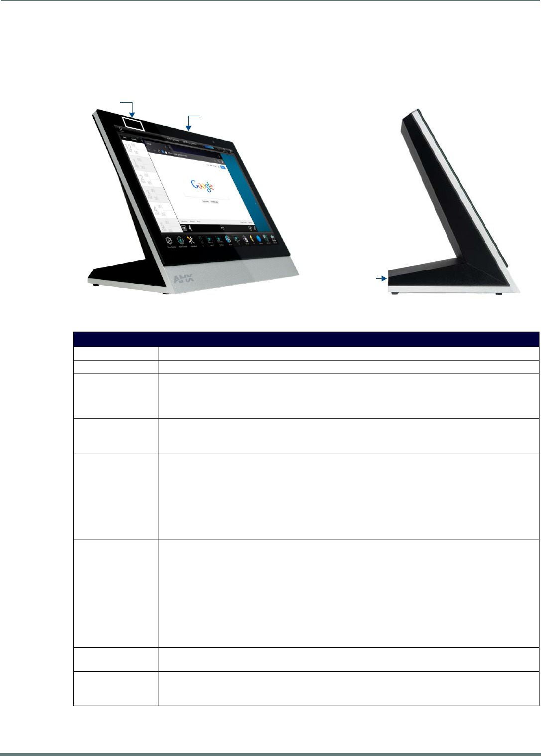
MXT-701 Specifications
FIG. 12 MXT-701 touch panel
MXT-701 Specif ications
DIMENSIONS (HWD) 5" x 7 5/16" x 4 1/8" (126mm x 187mm x 105mm)
WEIGHT 1.9 lbs (0.86 Kg)
POWER CONSUMPTION • Full-On: 11.5W maximum
• Standby: 5.8W
• Shutdown: 1W
• Start-Up Inrush Current: Not applicable due to PoE standard
EXTERNAL POWER
SUPPLY REQUIRED:
Optimal performance requires use of one of the following AMX PoE power supplies (not included):
• PS-POE-AF-TC, PoE Injector, 802.3AF Compliant (FG423-83)
• NXA-ENET8-2POE, Gigabit PoE Ethernet Switch (FG2178-63)
CERTIFICATIONS • FCC Part 15 Class B
• C-Tick CISPR 22 Class B
• CE EN 55022 Class B and EN 55024
• CB Scheme IEC 60950-1
•IC
• IEC/EN-60950
•UL 60950-1
•RoHS/WEEE compliant
TOUCH SCREEN
DISPLAY
• Display Type: TFT Active Matrix Color LCD with Fringe Field Switching (FFS) - Wide Viewing Angle Technology
• Display Size (WH): Landscape: 7.3" x 4.8" (186mm x 122mm), 8.8" (222mm) diagonal
• Viewable Area (WH): Landscape: 6.05" x 3.54" (154mm x 90mm), 7.0" (178mm) diagonal
• Resolution (WH): Landscape: 1024x600
• Aspect Ratio (WH): Landscape: 16:9
• Brightness: 400 cd/m2
• Contrast Ratio: 800:1
• Color Depth: 16.7M colors
• Illumination: LED
• Touch Overlay: Projected capacitive, multi-touch support, 3 simultaneous max
VIEWING ANGLE • Vertical: ± 89°
• Horizontal: ± 89°
MEMORY • SDRAM: 2 MB
•Flash: 16 GB
• Maximum Project Size: 12 GB flash, available for apps and touch panel files
Sleep Button
NFC Sensor
USB Ports (2)
MXT/D-701 - 7" X Series G5 Panels
27
Modero X® Series G5 Touch Panels - installation & Hardware Reference Manual
Touch Panel Aspect Ratio
While the touch panel screen physical dimensions fall between 16:9 and 16:10, any incoming video stream can be scaled to 16:9 if
needed. This may lead to some letter boxing around the video in some cases.
MXT-701 Specifications (Cont.)
COMMUNICATIONS • Ethernet: 10/100 Auto MDI-X port, RJ-45 connector. Supported IP and IP-Based Protocols: UCP, TCP, ICMP,
ICSP, IGMP, DHCP, SSH, FTP, DNS, RFB (for VNC), HTTP
• USB: (2) USB host 2.0, Type A ports (1 with limited physical access requiring right angle connection):
Firmware upgrade, Touch Panel File Transfer, document and image viewing, HID Peripherals
• Near Field Communication (NFC): Supports standards ISO/IEC 15693, ISO/IEC 14443A, ISO/IEC 14443B;
Unique Identifier (UID), typ range=.25", max = .5"
•Bluetooth*
Mouse/Keyboard: HID Profile v1.1, requires MXA-BT Bluetooth Adapter (FG5968-19)
Handset: Hands Free Profile v1.5, Headset Profile v1.2, requires MXA-BT Bluetooth Adapter (FG5968-19) and
MXA-HST Bluetooth Handset (FG5968-17)
VIDEO • Supported Video Codecs:
MPEG2-TS: MPEG-2 Main Profile@High Level up to 720p at 25 fps (decode only)
MPEG-2-TS: H.264 High Profile@Layer 4, AAC-LC up to 720p at 25 fps (decode)
MJPEG up to 720p at 25 fps (decode only)
• Supported Video Transport Streams: MPEG-TS for MPEG2 and H.264; HTTP for MJPEG
• Max Number of Active Video Streams: 2 (720dpi/30fps)
AUDIO • Microphone: -42 dB ±3 dB sensitivity FET microphone
• Speakers: 4 ohm, 2 Watt, 300 Hz cutoff frequency
• Supported Audio Codecs: MP2 Layer I and II, MP3 (8 kHz, 11.025 kHz, 12 kHz, 16 kHz, 22.05 kHz, 24 kHz,
32 kHz, 44.1 kHz, 48 kHz), AAC-LC (8 kHz, 96 kHz), G.711 with μLaw (VoIP* encode/decode at 8 kHz)
Suggested max packet size for G.711 Voice: 20ms
• File Formats: WAV, MP3 (as part of touch panel file only - no USB storage)
•Intercom*: Full Duplex VoIP, SIP v2.0
GRAPHICS ENGINE AMX G5: G5 enhanced feature set supporting multi-touch and gestures, scrolling, transitions, applications - See
TPD5 Operations Guide for more information
EMBEDDED
APPLICATIONS
• Viewer Applications*: PDF, JPEG, BMP, PNG, TIFF, GIF
• Remote Management: VNC Server
• Video Conferencing: Skype, the MXT-701 receives audio/video and returns audio
• Audio Conferencing: Audio (Full Duplex Intercom*)
FRONT PANEL
COMPONENTS
• Light Sensor: Photosensitive light detector for automatic adjustment of the panel brightness
• Proximity Detector: Max range = ~3', typ range = ~1', FOV = ~10 degrees
• Sleep Button: Sleep button to activate sleep mode and powering off. Also provides access to setup pages (can
be disabled)
CONNECTIONS • Ethernet: 10/100 port, RJ-45 connector through cable extension
• USB: (2) USB host 2.0, Type A ports
• Power: PoE (Power over Ethernet), 802.3af, class 3
ENVIRONMENTAL • Temperature (Operating): 32° F to 104° F (0° C to 40° C)
• Temperature (Storage): 4° F to 140° F (-20° C to 60° C)
• Humidity (Operating): 20% to 85% RH
• Humidity (Storage): 5% to 85% RH
• Power ("Heat") Dissipation:
On: 39.2 BTU/hr
Standby: 19.8 BTU/hr
INCLUDED
ACCESSORIES
• MXA-USB-C, USB Port Cover Kit, Modero X/S Series Touch Panel (FG5968-18)
• 3/4" Mini-Grommet (FG570-01)
• MXA-CLK, Modero X/S Series Cleaning Kit (FG5968-16)
OPTIONAL
ACCESSORIES
• MXA-MP, Modero X/S Series Multi Preview (FG5968-20)
• MXA-MPL, Modero X/S Series Multi Preview Live (FG5968-10)
• PS-POE-AF-TC, PoE Injector, 802.3AF Compliant (FG423-83)
• HPG-10-10K, 3/4" Mini-Grommet, 10-Pack (FG570-01-10K)
• MXA-BT Bluetooth USB Adapter for Modero X/S Series (FG5968-19)
• MXA-CLK, Modero X/S Series Cleaning Kit (FG5968-16)
• NXA-ENET8-2POE, Gigabit PoE Ethernet Switch (FG2178-63)
• MXA-HST, Bluetooth Handset for Modero X/S Series Touch Panels (FG5968-17)
• MXA-USB-C, USB Port Covers for the Modero X/S Series Touch Panels (FG5968-18)
* This feature will be available upon release of a future firmware update.
MXT/D-701 - 7" X Series G5 Panels
28
Modero X® Series G5 Touch Panels - installation & Hardware Reference Manual
MXD-701 (Wall-Mount - Landscape/Portrait)
The MXD-701 is available in Portrait and Landscape layouts: .
MXD-701 Specifications
Portrait MXD-701-P FG5968-54
Landscape MXD-701-L FG5968-55
FIG. 13 MXD-701 Wall Mount (Portrait and Landscape)
MXD-701 Specifications
DIMENSIONS (HWD) • Landscape: 4 13/16" x 7 5/16" x 2 1/2" (122mm x 186mm x 63mm)
• Portrait: 7 5/16" x 4 13/16" x 2 1/2" (186mm x 122mm x 63mm)
WEIGHT 1.4 lbs (0.64 Kg)
POWER CONSUMPTION • Full-On: 11.5 W maximum
• Standby: 5.8 W
• Shutdown: 1 W
• Start-Up Inrush Current: Not applicable due to PoE standard
EXTERNAL POWER
SUPPLY REQUIRED
Optimal performance requires use of one of the following AMX PoE power supplies (not included):
• PS-POE-AF-TC, PoE Injector, 802.3AF Compliant (FG423-83)
• NXA-ENET8-2POE, Gigabit PoE Ethernet Switch (FG2178-63)
CERTIFICATIONS • FCC Part 15 Class B
• C-Tick CISPR 22 Class B
• CE EN 55022 Class B and EN 55024
• CB Scheme IEC 60950-1
•IC
• IEC/EN-60950
•UL 60950-1
•RoHS/WEEE compliant
Sleep ButtonNFC Sensor
Sleep Button
NFC Sensor
Landscape
Portrait

MXT/D-701 - 7" X Series G5 Panels
29
Modero X® Series G5 Touch Panels - installation & Hardware Reference Manual
MXD-701 Specifications (Cont.)
TOUCH SCREEN
DISPLAY
• Display Type: TFT Active Matrix Color LCD with Fringe Field Switching (FFS) - Wide Viewing Angle Technology
•Display Size (WH):
Landscape: 7.3" x 4.8" (186mm x 122mm), 8.8" (222mm) diagonal
Portrait: 4.8" x 7.3" (122mm x 186mm), 8.8" (222mm) diagonal
• Viewable Area (WH):
Landscape: 6.05" x 3.54" (154mm x 90mm), 7.0" (178mm) diagonal
Portrait: 3.54" x 6.05" (90mm x 154mm), 7.0" (178mm) diagonal
•Resolution:
Landscape: 1024x600
Portrait: 600x1024
• Aspect Ratio:
Landscape: 16:9
Portrait: 9:16
• Brightness: 400 cd/m2
• Contrast Ratio: 800:1
• Color Depth: 16.7M colors
• Illumination: LED
• Touch Overlay: Projected capacitive, multi-touch support, 3 simultaneous max
VIEWING ANGLE • Vertical: ± 89°
• Horizontal: ± 89°
MEMORY • SDRAM: 2 GB
•Flash: 16 GB
• Maximum Project Size: 12 GB flash, available for apps and touch panel files
COMMUNICATIONS • Ethernet: 10/100 Auto MDI-X port, RJ-45 connector. Supported IP and IP-Based Protocols: UCP, TCP, ICMP,
ICSP, IGMP, DHCP, SSH, FTP, DNS, RFB (for VNC), HTTP
• USB: (2) USB host 2.0, Type A ports (1 with limited physical access requiring right angle connection):
Firmware upgrade, Touch Panel File Transfer, document and image viewing, HID Peripherals
• Near Field Communication (NFC): Supports standards ISO/IEC 15693, ISO/IEC 14443A, ISO/IEC 14443B;
Unique Identifier (UID), typ range=.25", max = .5"
•Bluetooth*:
Mouse/Keyboard: HID Profile v1.1, requires MXA-BT Bluetooth Adapter (FG5968-19)
Handset: Hands Free Profile v1.5, Headset Profile v1.2, requires MXA-BT Bluetooth Adapter (FG5968-19) and
MXA-HST Bluetooth Handset (FG5968-17)
VIDEO • Supported Video Codecs:
MPEG2-TS: MPEG-2 Main Profile@High Level up to 720p at 25 fps (decode only)
MPEG-2-TS: H.264 High Profile@Layer 4, AAC-LC up to 720p at 25 fps (decode)
MJPEG up to 720p at 25 fps (decode only)
• Supported Video Transport Streams: MPEG-TS for MPEG2 and H.264; HTTP for MJPEG
• Max Number of Active Video Streams: 2 (720dpi/30fps)
AUDIO • Microphone: -42 dB ±3 dB sensitivity FET microphone
• Speakers: 4 ohm, 2 Watt, 300 Hz cutoff frequency
• Supported Audio Codecs: MP2 Layer I and II, MP3 (8 kHz, 11.025 kHz, 12 kHz, 16 kHz, 22.05 kHz, 24 kHz,
32 kHz, 44.1 kHz, 48 kHz), AAC-LC (8 kHz, 96 kHz), G.711 with μLaw (VoIP* encode/decode at 8 kHz)
Suggested max packet size for G.711 Voice: 20ms
• File Formats: WAV, MP3 (as part of touch panel file only - no USB storage)
•Intercom*: Full Duplex VoIP, SIP v2.0
GRAPHICS ENGINE AMX G5: G5 enhanced feature set supporting multi-touch and gestures, scrolling, transitions, applications - See
TPD5 Operations Guide for more information
EMBEDDED
APPLICATIONS
• Viewer Applications*: PDF, JPEG, BMP, PNG, TIFF, GIF
• Remote Management: VNC Server
• Video Conferencing: Skype, the MXD-701 receives audio/video and returns audio
• Audio Conferencing: Audio (Full Duplex Intercom*)
FRONT PANEL
COMPONENTS
• Light Sensor: Photosensitive light detector for automatic adjustment of the panel brightness
• Proximity Detector: Max range = ~3', typ range = ~1', FOV = ~10 degrees
• Sleep Button: Sleep button to activate sleep mode and powering off. Also provides access to setup pages (can
be disabled)
CONNECTIONS • Ethernet: 10/100 port, RJ-45 connector through cable extension
• USB: (2) USB host 2.0, Type A ports
• Power: PoE (Power over Ethernet), 802.3af, class 3
MXT/D-701 - 7" X Series G5 Panels
30
Modero X® Series G5 Touch Panels - installation & Hardware Reference Manual
Touch Panel Aspect Ratio
While the touch panel screen physical dimensions fall between 16:9 and 16:10, any incoming video stream can be scaled to 16:9 if
needed. This may lead to some letter boxing around the video in some cases.
MXD-701 Specifications (Cont.)
ENVIRONMENTAL • Temperature (Operating): 32°F to 104°F (0°C to 40°C)
• Temperature (Storage): 4°F to 140°F (-20°C to 60°C)
• Humidity (Operating): 20% to 85% RH
• Humidity (Storage): 5% to 85% RH
• Power ("Heat") Dissipation:
On: 39.2 BTU/hr
Standby: 19.8 BTU/hr
INCLUDED
ACCESSORIES
• MXA-USB-C, USB Port Cover Kit, Modero X Series Touch Panel (FG5968-18)
• MXA-CLK, Modero X/S Series Cleaning Kit (FG5968-16)
• Installation Template, 7" Modero X Series (68-5968-04)
OPTIONAL
ACCESSORIES
• MXA-FMK-07 Flush Mount Kit, 7" Modero X Wall Mount (FG5968-71)
• MXA-RMK-07 Modero X Series Rack Mount Kit (FG5969-63)
• MXA-MP, Modero X/S Series Multi Preview (FG5968-20)
• MXA-MPL, Modero X/S Series Multi Preview Live (FG5968-10)
• PS-POE-AF-TC, PoE Injector, 802.3AF Compliant (FG423-83)
• CB-MXSA-07, Rough-In Box, Modero X/S Series Touch Panel, 7" (FG039-18)
• CB-MXP7, Rough-In Box (FG039-18)
• CB-MXP-07-F, Flush Mount Rough-In Box and Cover Plate, for use with MXA-FMK-07 Flush Mount Kit for 7"
Modero X Wall Mount Touch Panels (FG5968-83)
• MXA-BT Bluetooth USB Adapter for Modero X/S Series (FG5968-19)
• MXA-CLK, Modero X/S Series Cleaning Kit (FG5968-16)
• NXA-ENET8-2POE, Gigabit PoE Ethernet Switch (FG2178-63)
• MXA-USB-C, USB Port Cover Kit, Modero X Series Touch Panel (FG5968-18)
• MXA-HST, Bluetooth Handset for Modero X/S Series Touch Panels (FG5968-17)
* This feature will be available upon release of a future firmware update.
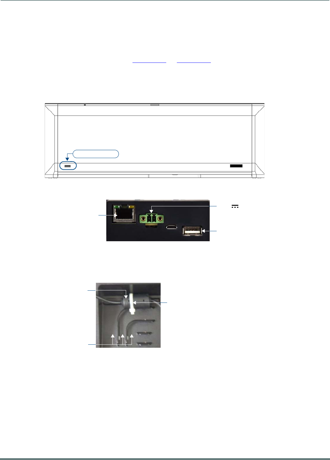
Installing Tabletop (MXT) Panels
31
Modero X® Series G5 Touch Panels - installation & Hardware Reference Manual
Installing Tabletop (MXT) Panels
MXT-2001-PAN / MXT-1901-PAN
Detailed specifications drawings for the MXT-2001-PAN and MXT-1901-PAN are available to download from www.amx.com.
Connector Locations - MXT-2001-PAN / MXT-1901-PAN
Two Type A USB ports are located on the rear right corner of the panel (FIG. 14). USB peripherals (i.e. mouse, keyboard) may be
connected to either of the two USB ports on the rear of the device. Updates to the device’s firmware can also made via the USB
ports (see the Modero G5 Configuration and Programming Guide for details). Note that FIG. 14 shows the MXT-1901-PAN, but the
USB ports are in a similar location on the MXT-2001-PAN.
The Power and Ethernet connectors, as well as an additional USB port are located on the bottom of the device (FIG. 15).
NOTE: Refer to the Power via 13.5V section on page 32 for details on wiring a power connection.
The underside USB port, as well as the two rear USB ports, may be used with a flash drive for page transfers or firmware upgrades.
The MXT-2001-PAN and MXT-1901-PAN have a slot at the base with channels for securing power and Ethernet cables, to allow
options for cable configuration (FIG. 16).
Each channel side has slots for attaching tie-wraps to secure each cable.
The ferrite on the power cable must be secured with the included tie-wrap during installation to prevent the possibility of
the panel not sitting flush on the table.
Other cables may be secured with tie-wraps if desired.
FIG. 14 MXT-1901-PAN - rear view
FIG. 15 MXT-2001-PAN / MXT-1901-PAN - underside connectors
FIG. 16 Tie-wrap for power connector ferrite
Type A USB Ports
Ethernet 10/100 Port
Type A USB Port
13.5V Power Port
Tie-wrap channels
Tie-wrap
Ferrite
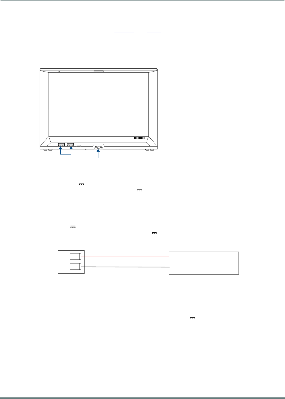
Installing Tabletop (MXT) Panels
32
Modero X® Series G5 Touch Panels - installation & Hardware Reference Manual
MXT-1001 / MXT-701
Detailed specifications drawings for the MXT-1001 and MXT-701 are available to download from www.amx.com.
Connector Locations - MXT-1001/MXT-701
Two Type A USB ports are located on the rear right corner of the panel (FIG. 17). USB peripherals (i.e. mouse, keyboard) may be
connected to either of the two USB ports on the rear of the device. Updates to the device’s firmware can also made via the USB
ports (see the Modero G5 Configuration and Programming Guide for details). Note that FIG. 17 shows the MXT-1001, but the USB
ports are in a similar location on the MXT-701.
NOTE: Refer to the Power via PoE section on page 32 for details on PoE and Ethernet Cable Installation and Modification.
Power via 13.5V
The MXT-2001-PAN and MXT-1901-PAN use a 13.5V -compliant power supply to provide power to the panel via the 2-pin 3.5mm
captive wire PWR connector. The incoming PWR and GND wires from the power supply must be connected to the corresponding
locations within the PWR connector.
NOTE: Connecting power to the panel should be done using the included 2-pin 3.5mm captive wire connector included with the
device. This connector is retained within its port with locking screws instead of the pins on each side of standard captive wire
connectors, and using force to insert a standard captive wire connector may damage the device.
Wiring a 13.5V Power Connection
To use the 2-pin 3.5mm captive wire connector with a 13.5V -compliant power supply, the incoming PWR and GND wires from
the external source must be connected to their corresponding locations on the connector (FIG. 18). The connector uses locking
screws to insure a connection to the device, so make sure to insert and tighten the screws before applying power.
1. Insert the PWR and GND wires on the terminal end of the 2-pin 3.5mm captive wire cable.
Match the wiring locations of the +/- on both the power supply and the terminal connector.
2. Tighten the clamp to secure the two wires.
Do not tighten the screws excessively; doing so may strip the threads and damage the connector.
3. Verify the connection of the 2-pin 3.5mm captive wire to the external 13.5V -compliant power supply and apply power.
Power via PoE
Power for the MXT-1001 and MXT-701 is supplied via PoE (Power Over Ethernet), utilizing an AMX-certified, capacitive touch-
compliant PoE injector such as the PS-POE-AT High Power PoE Injector (FG423-81) or other approved AMX PoE power source.
The incoming Ethernet cable should be connected to the RJ45 port on the cable attached to the device.
FIG. 17 MXT-1001 - rear view
FIG. 18 NetLinx power connector wiring diagram
USB Ports Entry for RJ45/PoE Cable
PWR +
GND -
To the Touch Panel
Power Supply
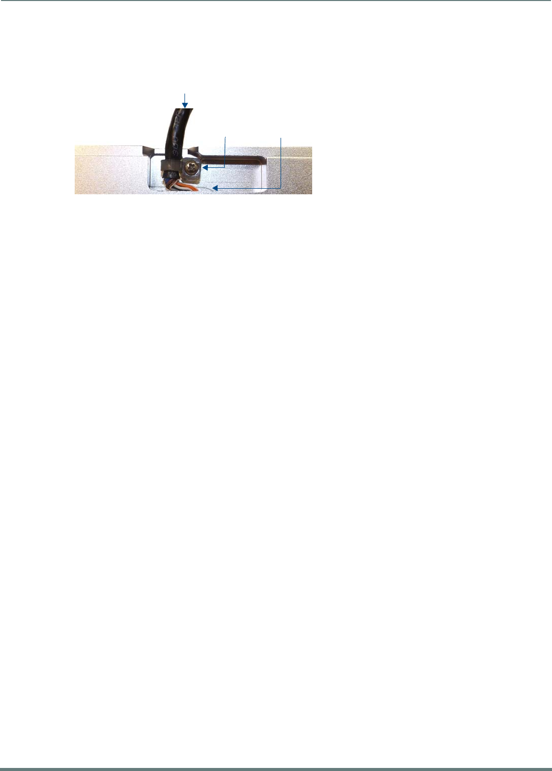
Installing Tabletop (MXT) Panels
33
Modero X® Series G5 Touch Panels - installation & Hardware Reference Manual
Ethernet Cable Installation and Modification
In tabletop installations where concealing the Ethernet cable is desired, a hole at least 1.00” (2.54 cm) in diameter is required in
the surface to allow passage of the female RJ45 connector (FIG. 19). If using a smaller hole is unavoidable, you will need to
disconnect the Ethernet cable (ECA5968-05) from the device, to feed the male end of the cable through.
NOTE: The minimum diameter hole through which the Ethernet cable may pass is 0.50" (1.27 cm).
To disconnect and reconnect the Ethernet cable on the MXT-701 and MXT-1001to allow use of a hole smaller than 1.00” in
diameter:
1. On a soft surface, turn the MXT-1001 face-down to access the bottom of the device.
2. Remove the clamp holding the Ethernet cable (FIG. 19).
3. Remove the Ethernet cable connector and pull the cable out of the clamp.
4. Pass the Ethernet cable (ECA5968-05) through the hole, with the RJ45 connector on the other side of the installation surface
from the device.
5. Press the Ethernet cable back into the clamp.
Do NOT tighten the clamp at this time.
6. Using a non-conductive item such as a wooden stick, reinsert the Ethernet cable connector into the device. Ensure that the
connector is properly seated.
7. Tighten the clamp to secure the Ethernet cable.
Make sure the clamp is around the bundled black cable, not the individual wires
8. Connect the RJ45 connector to its incoming Ethernet cable and apply power.
FIG. 19 Bottom of the MXT-701/1001
Ethernet Cable
Connector
Clamp
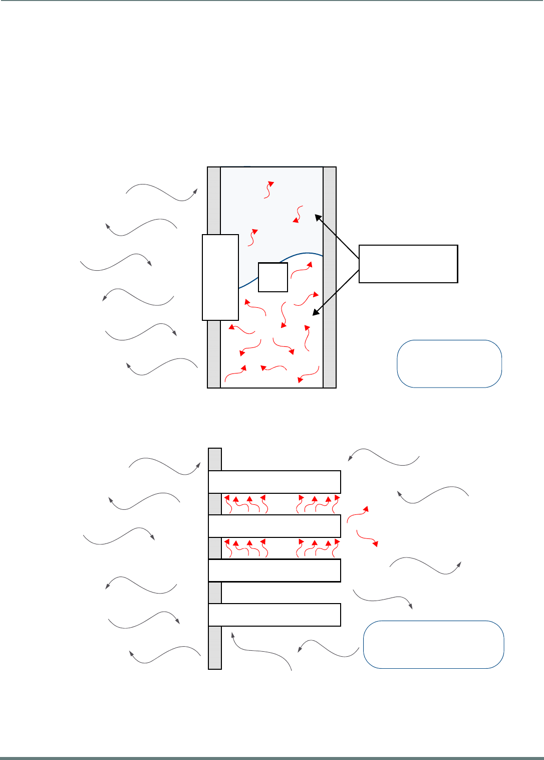
Installing Wall-Mount (MXD) Panels
34
Modero X® Series G5 Touch Panels - installation & Hardware Reference Manual
Installing Wall-Mount (MXD) Panels
A Note About Wall and Rack Installation
Some products are installed in areas of differing temperature and cooling methodologies. These include products installed in walls,
racks, cabinets, etc. Those areas may have different temperatures and/or cooling approaches that must be taken into consideration
to maintain the product within the specified operating temperature.
FIG. 20 shows an AMX device installed in a wall with a filled volume (such as with insulation or concrete), as well as with a closed
volume (such as between studs in an otherwise finished wall). The diagram shows how heat generated by the device or other
devices may have no way to escape, and may build up to levels that may affect device operation.
In FIG. 21, the diagram displays an AMX device in a typical rack mounting, with full air circulation around the front and back of the
device. In this case, the main concern is with heat building up between components, possibly to levels that may affect device
operation.
FIG. 20 Heat convection in filled or closed volume, limited or no convection
FIG. 21 Heat convection in rack-mounted devices
AMX DEVICE
T2
T1
FILLED OR CLOSED
VOLUME, LIMITED OR
NO CONVECTION
T1, T2 < TOpMax
T1, T2 > TOpMin
T1 AMX DEVICE
T3
T4
T2
RACK MOUNTED DEVICES
T1, T2, T3, T4 < TOpMax
T1, T2, T3, T4 > TOpMin
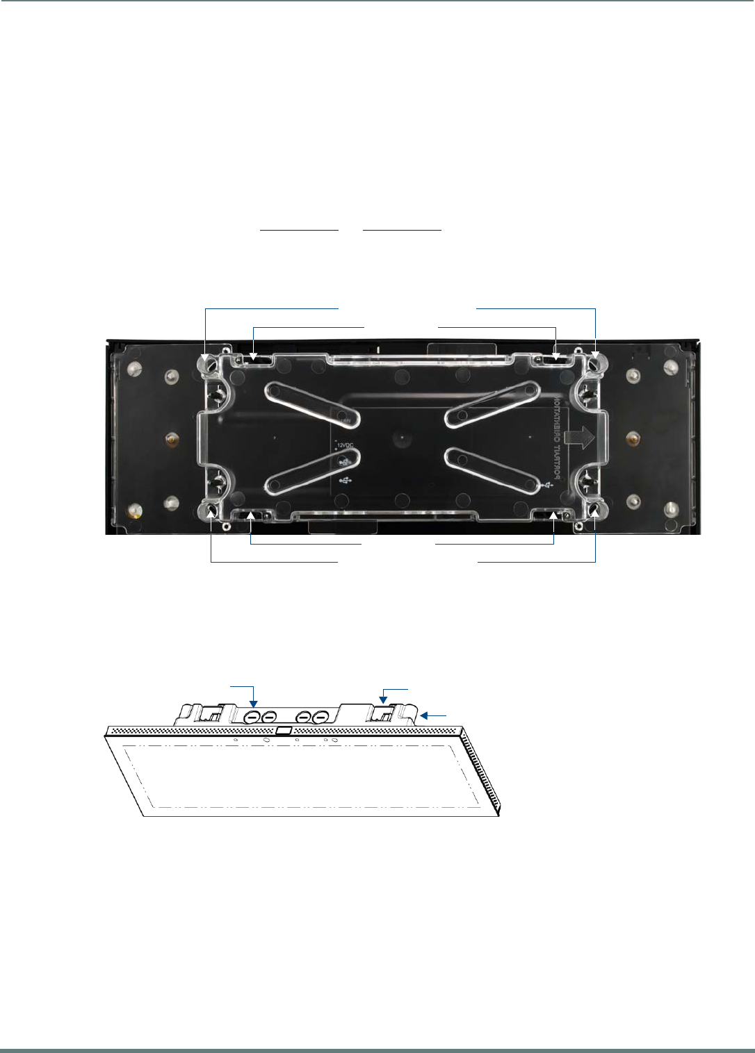
Installing Wall-Mount (MXD) Panels
35
Modero X® Series G5 Touch Panels - installation & Hardware Reference Manual
Installation Recommendations
During any installation, a lack of ventilation may produce conditions that may adversely affect the device’s operation. In these
circumstances, special care must be made to make sure that temperatures within enclosed areas do not exceed the device’s
maximum rated temperature.
NOTE: While the outside temperature of the device may be at or below its maximum operating temperature, special care must be
taken before and during installation to ensure that the maximum operating temperature is not exceeded within wall or rack
installation spaces.
MXD-2001-PAN / MXD-1901-PAN Installation
Note that the figures in this section show landscape (-L) panels, but the concepts presented here apply equally to portrait (-P)
panels, since the hardware is the same for landscape and portrait panels except for the horizontal / vertical orientation. Detailed
specifications drawings for the MXD-2001-PAN and MXD-1901-PAN are available to download from www.amx.com.
MXD-2001-PAN and MXD-1901-PAN panels may be installed directly into a solid surface, using either solid surface screws or the
included locking tabs for different mounting options.
Once installed, the panel is contained within a clear outer housing known as the Backbox (FIG. 22). This Backbox is removed when
installing the device into a wall or when using the optional Rough-In Box accessory (FG039-15).
NOTE: For typical mounting surfaces, such as drywall, use the locking tabs as the primary method for securing the Backbox to the
surface. For thin walls or solid surfaces, use mounting screws (not included).
Installing the MXD-2001-PAN / MXD-1901-PAN Into a Wall
The Backbox has four locking tabs (two on top and two on bottom) to lock the Backbox to the wall (FIG. 23). Note that FIG. 23
shows the MXD-1901-PAN, but the locking tabs are in a similar location on the MXT-2001-PAN.
These locking tabs are only extended AFTER the Backbox is inserted into the wall.
The Backbox also has four slots for accepting the temporary mounting posts on the back of the device.
NOTE: When installing the Backbox, make sure that the assembly is in the correct position and in the correct place. Once the locking
tabs are extended and locked into place, removing the Backbox may be diff icult without having access to the back of the wall or
causing damage to the wall.
FIG. 22 Backbox (MXD-2001-PAN / MXD-1901-PAN)
FIG. 23 MXD-1901-PAN (Landscape)
Locking Tabs
Locking Tabs
Tempo rary Mount ing Po sts
Temporary Mounting Posts
Backbox
Backbox knockouts (X8) Locking tabs (X4)
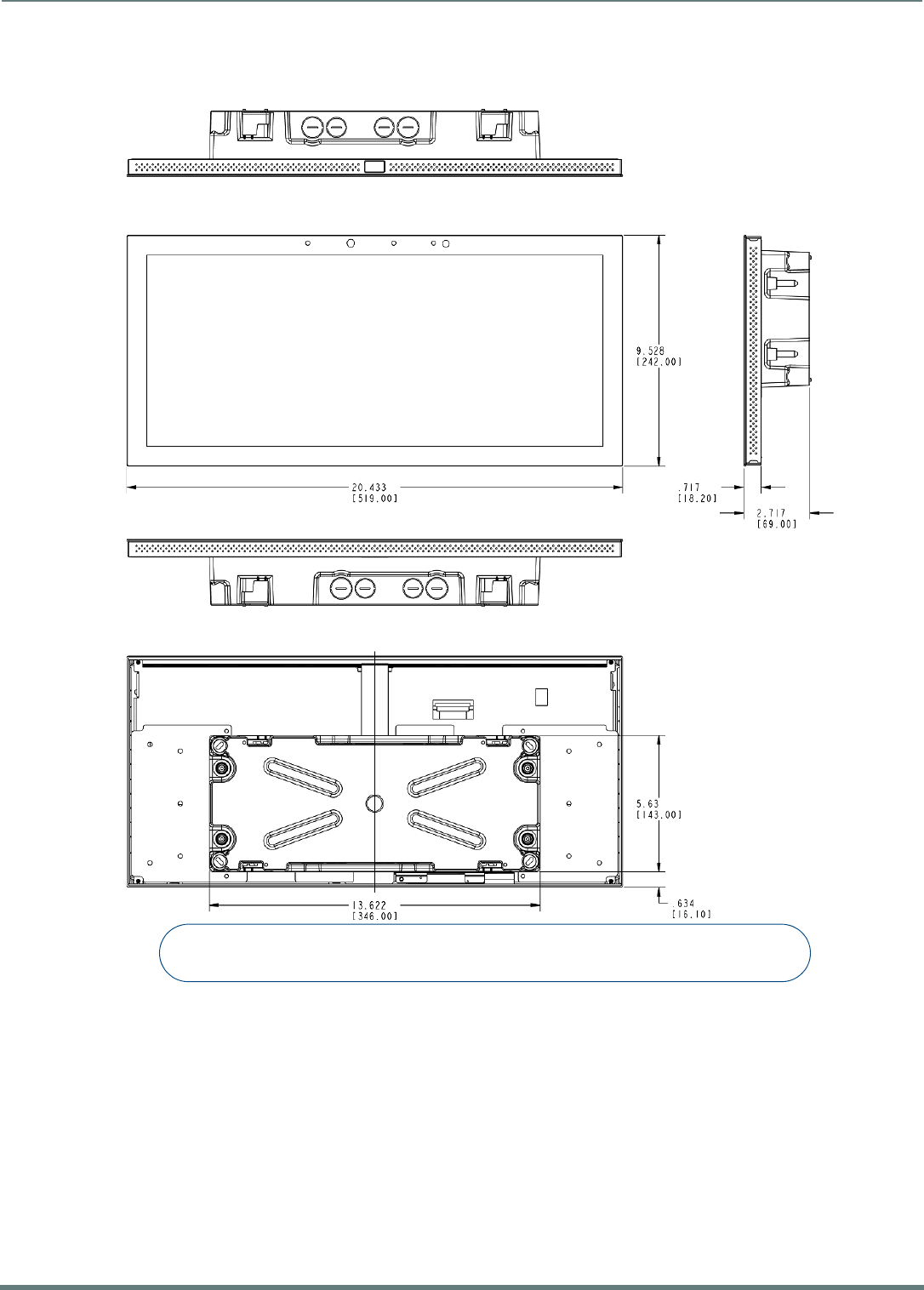
Installing Wall-Mount (MXD) Panels
36
Modero X® Series G5 Touch Panels - installation & Hardware Reference Manual
MXD-2001-PAN Dimensions
FIG. 24 provides dimensions for the MXD-2001-PAN:
FIG. 24 MXD-2001-PAN - Dimensions
Notes:
Dimensions in parenthesis are in millimeters
Additional detailed installation and product drawings are available to view/download at www.amx.com
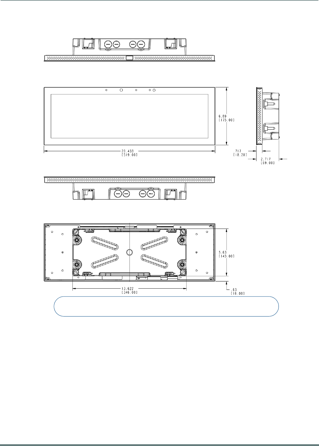
Installing Wall-Mount (MXD) Panels
37
Modero X® Series G5 Touch Panels - installation & Hardware Reference Manual
MXD-1901-PAN Dimensions
FIG. 25 provides dimensions for the MXD-1901-PAN:
NOTE: In order to ensure a stable installation, the thickness of the wall material must be a minimum of .50 inches (1.27cm) and a
maximum of .875 inches (2.22cm).
FIG. 25 MXD-1901-PAN - Dimensions
Notes:
Dimensions in parenthesis are in millimeters
Additional detailed installation and product drawings are available to view/download at www.amx.com
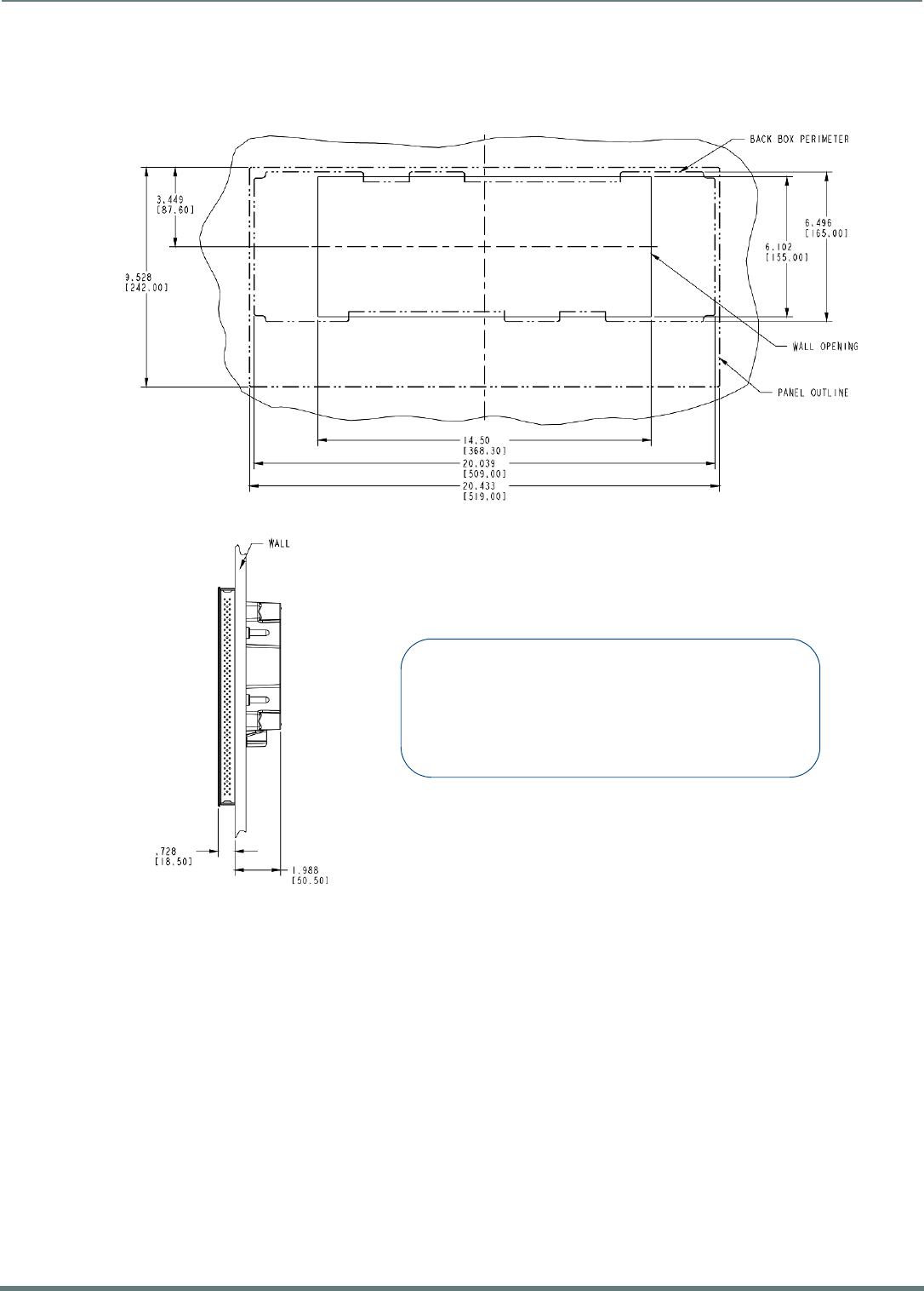
Installing Wall-Mount (MXD) Panels
38
Modero X® Series G5 Touch Panels - installation & Hardware Reference Manual
Installing the Backbox
MXD-2001-PAN Installation Dimensions
FIG. 26 and FIG. 27 provide installation dimensions for the MXD-2001-PAN:
FIG. 26 MXD-2001-PAN-L Installation Dimensions (front view)
FIG. 27 MXD-2001-PAN-L Installation Dimensions (side view)
Notes:
- Dimensions in parenthesis are in millimeters.
- These drawings show a Landscape panel. The dimensions
are the same for Portrait panels, except for the vertical orientation.
Additional detailed installation and product drawings (for both
Landscape and Portrait panels) are available to view/download
at www.amx.com
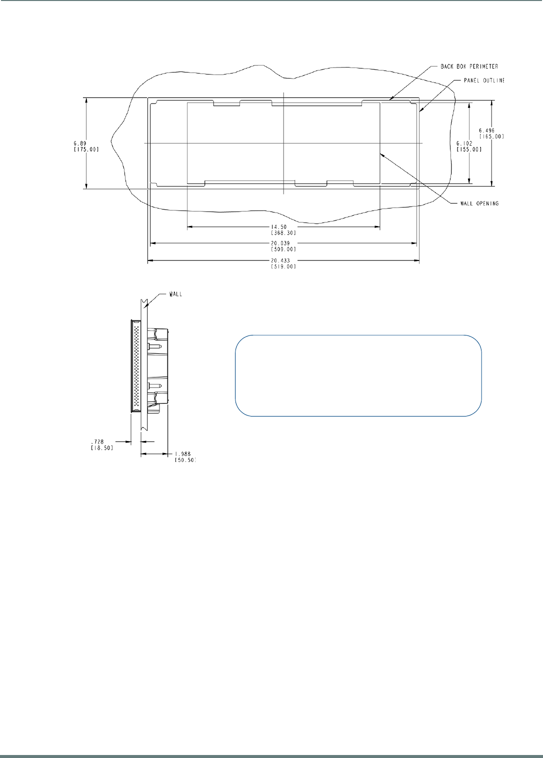
Installing Wall-Mount (MXD) Panels
39
Modero X® Series G5 Touch Panels - installation & Hardware Reference Manual
MXD-1901-PAN Installation Dimensions
FIG. 28 and FIG. 29 provide installation dimensions for the MXD-1901-PAN:
Since the cutout for the Backbox is off-center from the edges of the touch panel, use the included Installation Template to ensure
proper placement.
NOTE: Using the Installation Template to select the f inal placement of the Backbox is highly recommended. The outside edges of the
template are the same dimensions as the touch panel, which allows you to troubleshoot possible conflicts with wall edges, doors, and
other potential obstacles.
The MXD-2001-PAN uses Installation Template 68-5968-01
The MXD-1901-PAN uses Installation Template 68-5968-02
1. Prepare the area by removing any screws or nails from the drywall before beginning the cutout process.
2. After ensuring proper placement, cut out the mounting surface for the Backbox, using the included Installation Template as a
guide.
NOTE: Making sure that the actual cutout opening is slightly smaller than the provided dimensions is highly recommended. This
action provides the installer with a margin for error if the opening needs to be expanded. Too little wall material removed is
always better than too much.
3. Thread the incoming power and Ethernet wiring from their terminal locations through the surface opening (FIG. 30).
Note that FIG. 30 shows the MXD-1901-PAN, but the illustration applies equally to the MXD-2001-PAN. Also note that FIG. 30
shows a landscape panel but the installation of a portrait panel is essentially the same, other than the vertical orientation.
Leave enough slack in the wiring to accommodate any re-positioning of the panel.
FIG. 28 MXD-1901-PAN-L Installation Dimensions (front view)
FIG. 29 MXD-1901-PAN-L Installation Dimensions (side view)
Notes:
- Dimensions in parenthesis are in millimeters.
- These drawings show a Landscape panel. The dimensions
are the same for Portrait panels, except for the vertical orientation.
Additional detailed installation and product drawings (for both
Landscape and Portrait panels) are available to view/download
at www.amx.com
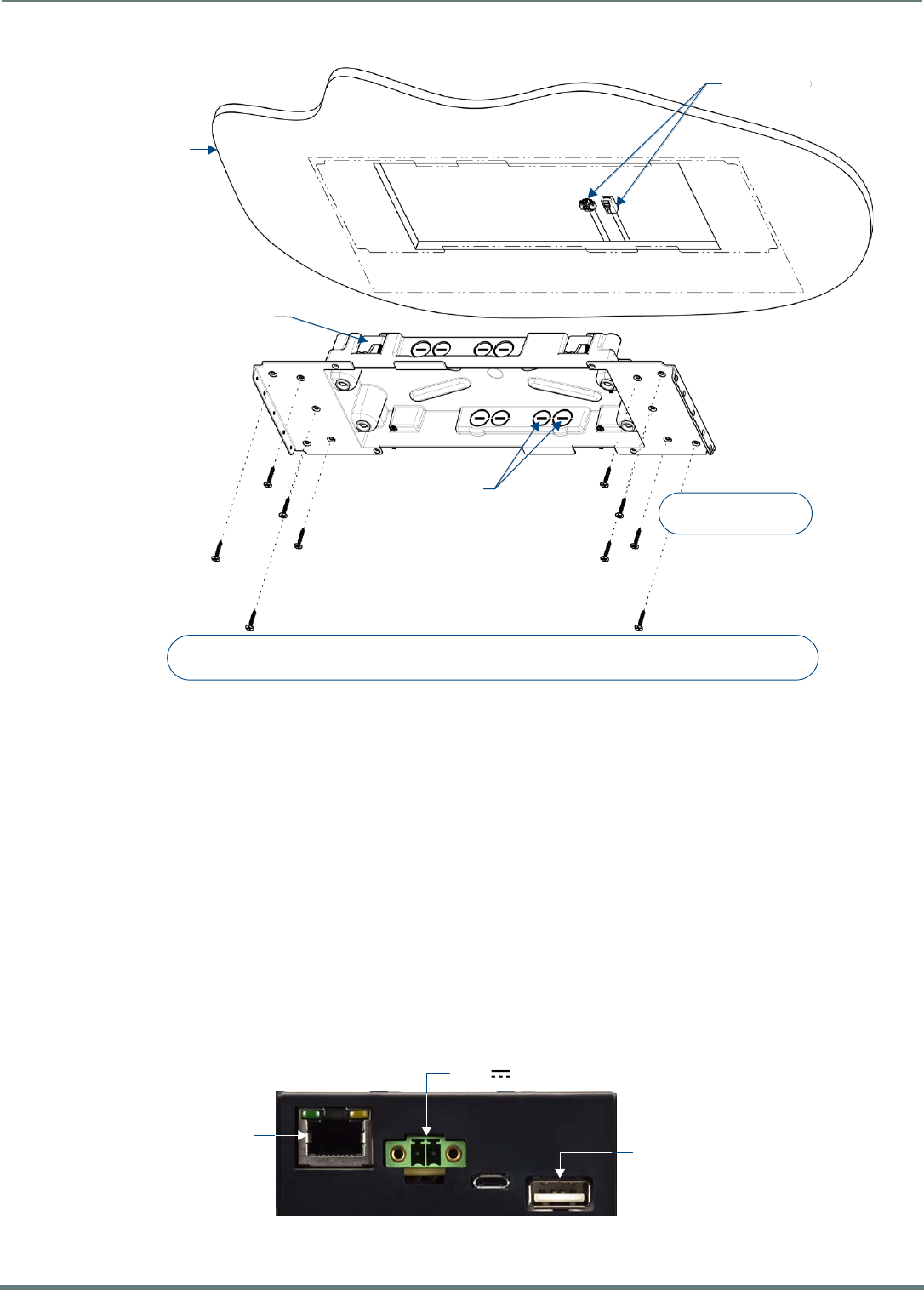
Installing Wall-Mount (MXD) Panels
40
Modero X® Series G5 Touch Panels - installation & Hardware Reference Manual
4. Remove any knockouts as needed on either long dimension of the Backbox to facilitate incoming wiring and pull the wiring
through the resultant holes.
5. Push the Backbox into the wall opening. Insure that the locking tabs lie flush against the Backbox, and that the Backbox goes
freely into the opening.
6. Extend the locking tabs on the sides of the Backbox by tightening the screws inside the box until snug.
NOTE: The maximum recommended torque to screw in the locking tabs on the plastic Backbox is 5 IN-LB [56 N-CM]. Applying
excessive torque while tightening the tab screws, such as with powered screwdrivers, can strip out the locking tabs or damage
the plastic Backbox.
Not all of the tabs must be extended to lock the Backbox in place, but extending a minimum of the top and bottom tabs is
highly recommended.
Apply enough pressure to the screw head to keep the box flush with the wall: this ensures that the locking tabs will tighten
up against the inside of the wall.
The Backbox is clear to allow visual confirmation that the tabs have been extended and are gripping the wall, as well as in
assisting with removal if necessary.
For additional strength, #4 mounting screws (not included) may be secured through circular holes located at the left and
right sides of the MXD-2001-PAN (see FIG. 30). In order to prevent damage to the touch panel, make sure that these are
flush with the Backbox.
7. Insert each connector into its corresponding location along the back of the device (FIG. 31).
FIG. 30 MXD-1901-PAN Backbox installation (Landscape)
FIG. 31 MXD-2001-PAN / MXD-1901-PAN - rear connectors
4X Installation Clamp
for Wall Thickness
.37 [12.01] to .98 [25.0]
Cables Routed to
Wall Opening
8X Knock Outs
Remove For Cable
Routing As Needed
Mounting screws
placement (optional)
Wall
Note:
Additional detailed installation and product drawings are available to view/download at www.amx.com
Ethernet 10/100 Port
Type A USB Port
(limited access)
13.5V Power Port
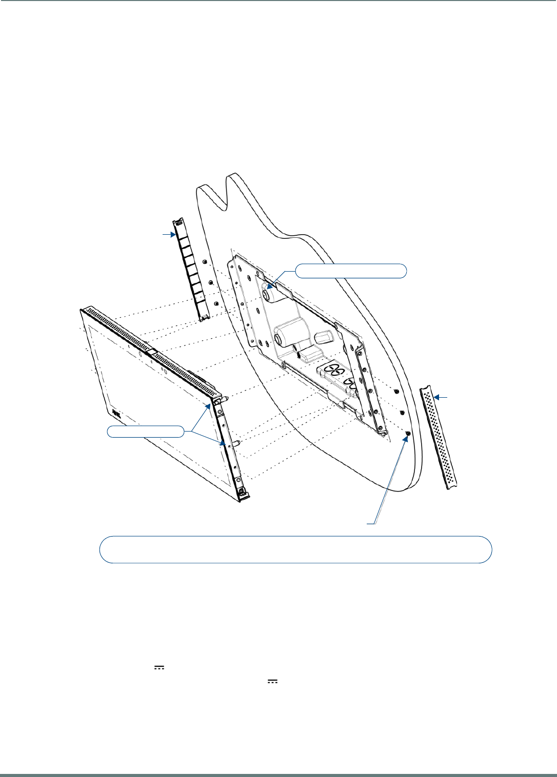
Installing Wall-Mount (MXD) Panels
41
Modero X® Series G5 Touch Panels - installation & Hardware Reference Manual
NOTE: Refer to the Power via 13.5V section on page 41 for details on wiring a power connection.
8. Test the incoming wiring by attaching the panel connections to their terminal locations and applying power. Verify that the
panel is receiving power and functioning properly to prevent repetition of the installation.
NOTE: Do not disconnect the connectors from the touch panel. The unit must be installed with the attached connectors before
being inserted into the drywall.
NOTE: Configurations that use the limited access USB port on the side of the connector box may require a right angle mating
connector (not included) for connection to the device.
9. Insert the four temporary mounting posts of the panel into the openings on the Backbox and slide the panel onto the Backbox
(FIG. 32). This will temporarily hold the panel during the rest of the installation.
Note that FIG. 32 shows the MXD-1901-PAN, but the illustration applies equally to the MXD-2001-PAN. Also note that FIG. 32
shows a landscape panel but the installation of a portrait panel is essentially the same, other than the vertical orientation.
NOTE: When installing the panel, do NOT press on or near the center of the panel. Too much stress at the center may damage
the touch screen surface. When installing the panel, pressure should be applied toward the ends of the panel ONLY.
10. Use the six provided screws, three at each end, to secure the touch panel to the Backbox.
Use only the provided screws, as other screws may damage the touch panel.
11. Snap the decorative side covers onto each end of the panel.
12. Reconnect the terminal Ethernet and USB cables to their respective ports.
Power via 13.5V
The MXT-2001-PAN and MXT-1901-PAN use a 13.5V -compliant power supply to provide power to the panel via the 2-pin 3.5mm
captive wire PWR connector. The incoming PWR and GND wires from the power supply must be connected to the corresponding
locations within the PWR connector.
NOTE: Connecting power to the panel should be done using the included 2-pin 3.5mm captive wire connector included with the
device. This connector is retained within its port with locking screws instead of the pins on each side of standard captive wire
connectors, and using force to insert a standard captive wire connector may damage the device.
FIG. 32 MXD-1901-PAN installation (Landscape)
Side cover
4X Mounting post openings
4X Mounting posts
Side cover
6X 4-40 X 1/4" LONG FLAT HEAD
TORQUE TO 5±.2 IN LBS
Note:
Additional detailed installation and product drawings are available to view/download at www.amx.com
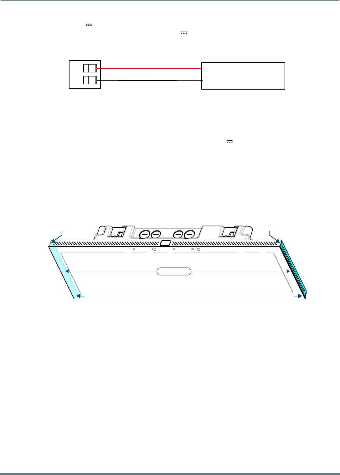
Installing Wall-Mount (MXD) Panels
42
Modero X® Series G5 Touch Panels - installation & Hardware Reference Manual
Wiring a 13.5V Power Connection
To use the 2-pin 3.5mm captive wire connector with a 13.5V -compliant power supply, the incoming PWR and GND wires from
the external source must be connected to their corresponding locations on the connector (FIG. 33).
The connector uses locking screws to insure a connection to the device, so make sure to insert and tighten the screws before
applying power.
1. Insert the PWR and GND wires on the terminal end of the 2-pin 3.5mm captive wire cable.
Match the wiring locations of the +/- on both the power supply and the terminal connector.
2. Tighten the clamp to secure the two wires.
Do not tighten the screws excessively; doing so may strip the threads and damage the connector.
3. Verify the connection of the 2-pin 3.5mm captive wire to the external 13.5V -compliant power supply and apply power.
Uninstalling the MXD-2001-PAN / MXT-1901-PAN
The MXD-2001-PAN and MXD-1901-PAN are secured to the Backbox via screws. In certain circumstances, such as firmware
updates or other maintenance that requires accessing the device’s USB or Micro-USB ports, the panel may need to be removed
from the Backbox.
The side covers must be removed to access the screws that secure the panel to the Backbox.
Removing the Panel From Its Backbox
1. The MXD-2001-PAN and MXD-1901-PAN have removable side covers on the left and right (landscape) or top and bottom
(portrait) (FIG. 34).
Note that FIG. 34 shows the MXD-1901-PAN, but the illustration applies equally to the MXD-2001-PAN. Also note that FIG. 34
shows a landscape panel but the installation of a portrait panel is essentially the same, other than the vertical orientation:
2. For each of the two side covers - insert a flat-head screwdriver (or similar tool) into the removal notches, and carefully prey
each side of the side cover free from the molding.
3. Once the side covers have been removed, the screws securing the panel to the Backbox are accessible.
4. Remove the screws on each side to free the panel from the Backbox.
5. Grasp the bottom of the panel (Landscape) or right side (Portrait) and pull gently outward until the side of the panel is free of
the Backbox. Use your other hand to hold stable the front of the panel.
Always pull on the frame of the touch panel. NEVER pull on the glass edge.
6. When the first side is free, repeat the process with the other.
7. With the edge of the touch panel free, carefully lift up and out (Landscape) or to the left and out (Portrait) to remove the touch
panel from the Backbox. Be careful not to pull on the cables or connectors.
8. To reattach the panel to its Backbox, repeat the installation procedure.
NOTE: For further information, refer to the video available at www.amx.com (go to Newsroom > Videos > Touch Panels).
FIG. 33 NetLinx power connector wiring diagram
FIG. 34 MXD-1901-PAN Side Covers (highlighted in blue)
PWR +
GND -
To the Touch Panel
Power Supply
Removal notch Removal notch
Side Covers
Removal notch Removal notch
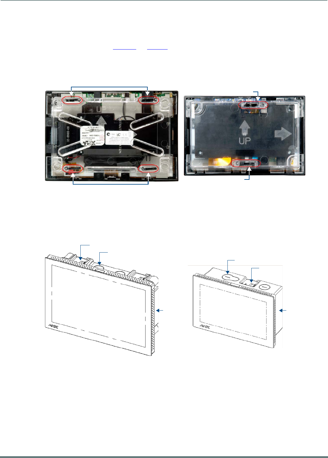
Installing Wall-Mount (MXD) Panels
43
Modero X® Series G5 Touch Panels - installation & Hardware Reference Manual
MXD-1001 / MXD-701 Installation
Note that the figures in this section show landscape (-L) panels, but the concepts presented here apply equally to portrait (-P)
panels, since the hardware is the same for landscape and portrait panels except for the horizontal / vertical orientation. Detailed
specifications drawings for the MXD-1001 and MXD-701 are available to download from www.amx.com.
MXD-1001 and MXD-701panels may be installed directly into a solid surface, using either solid surface screws or the included
locking tabs for different mounting options.
Once installed, the panel is contained within a clear outer housing known as the Backbox (FIG. 35). This Backbox is removed to
install the device into a wall or when using the optional Rough-In Box accessory (FG039-17).
NOTE: For typical mounting surfaces, such as drywall, use the locking tabs as the primary method for securing the Backbox to the
surface. For thin walls or solid surfaces, use mounting screws (not included).
Installing the MXD-1001 / MXD-701 Into a Wall
The Backbox has locking tabs to lock the Backbox to the wall - there are four on the MXD-1001 and two on the MXD-701 (FIG. 36).
These locking tabs are only extended AFTER the Backbox is inserted into the wall. (FIG. 23 and FIG. 24).
NOTE: When installing the Backbox, make sure that the assembly is in the correct position and in the correct place. Once the locking
tabs are extended and locked into place, removing the Backbox may be diff icult without having access to the back of the wall or
causing damage to the wall.
FIG. 35 MXD-1001 and MXD-701 Backboxes (Landscape orientation)
FIG. 36 MXD-1001 and MXD-701 (Landscape)
Locking tabs
Locking tabs
Locking tab
Locking tab
MXD-1001 MXD-701
Backbox knockouts (X4)
Locking tabs (X4)
Backbox knockouts (X4)
Locking tabs (X2)
Backbox
MXD-1001
MXD-701
Backbox
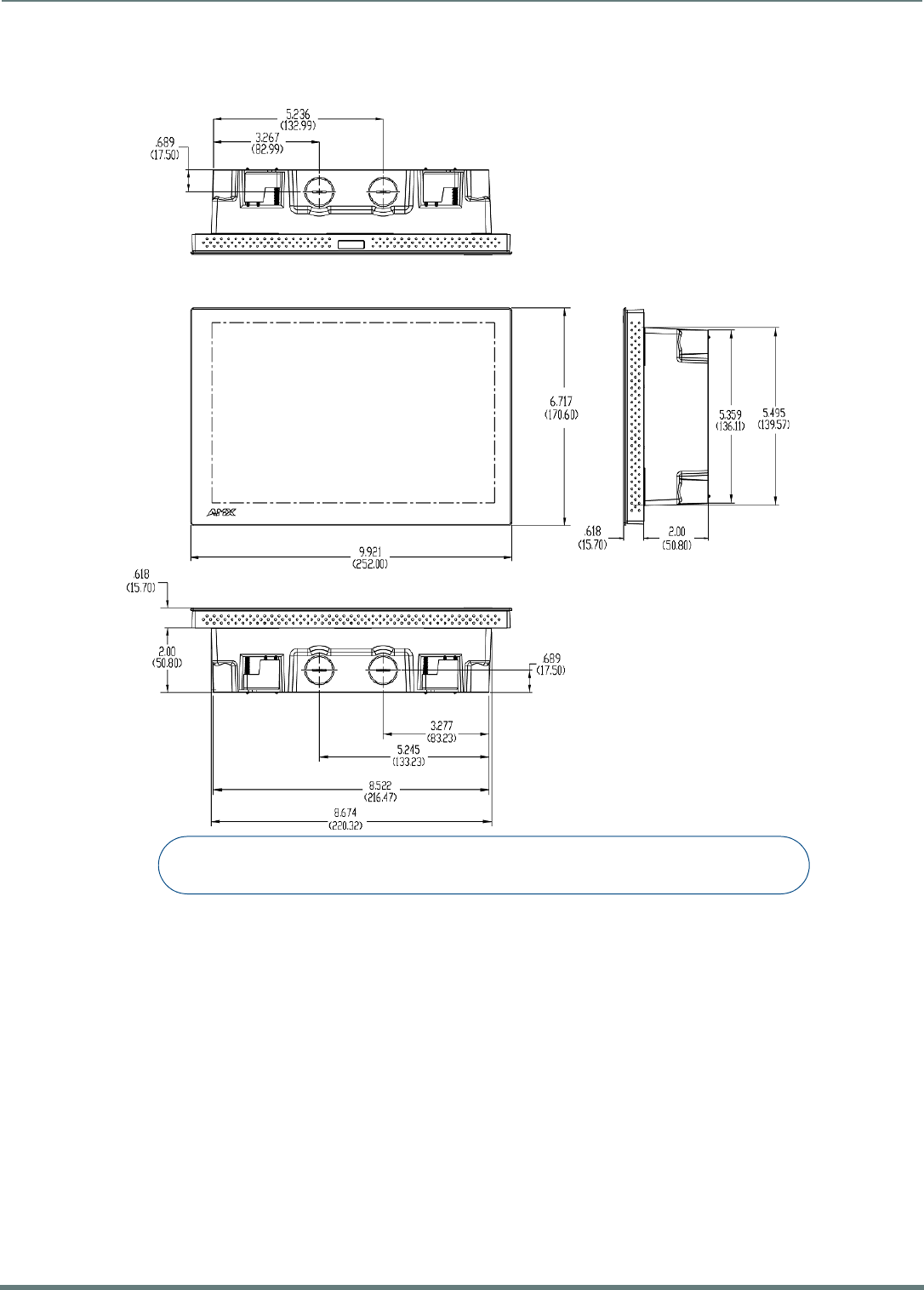
Installing Wall-Mount (MXD) Panels
44
Modero X® Series G5 Touch Panels - installation & Hardware Reference Manual
MXD-1001 Dimensions
FIG. 37 provides dimensions for the MXD-1001:
FIG. 37 MXD-1001 - Dimensions
Notes:
Dimensions in parenthesis are in millimeters
Additional detailed installation and product drawings are available to view/download at www.amx.com
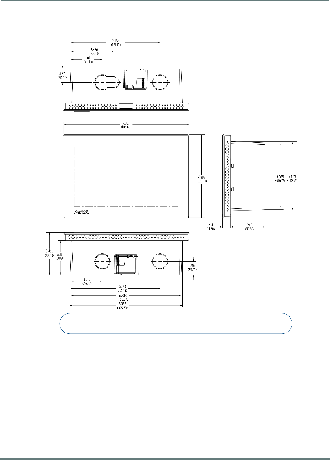
Installing Wall-Mount (MXD) Panels
45
Modero X® Series G5 Touch Panels - installation & Hardware Reference Manual
MXD-701 Dimensions
FIG. 37 provides dimensions for the MXD-701:
NOTE: In order to ensure a stable installation, the thickness of the wall material must be a minimum of .50 inches (1.27cm) and a
maximum of .875 inches (2.22cm). The mounting surface should also be smooth and flat.
FIG. 38 MXD-701 - Dimensions
Notes:
Dimensions in parenthesis are in millimeters
Additional detailed installation and product drawings are available to view/download at www.amx.com
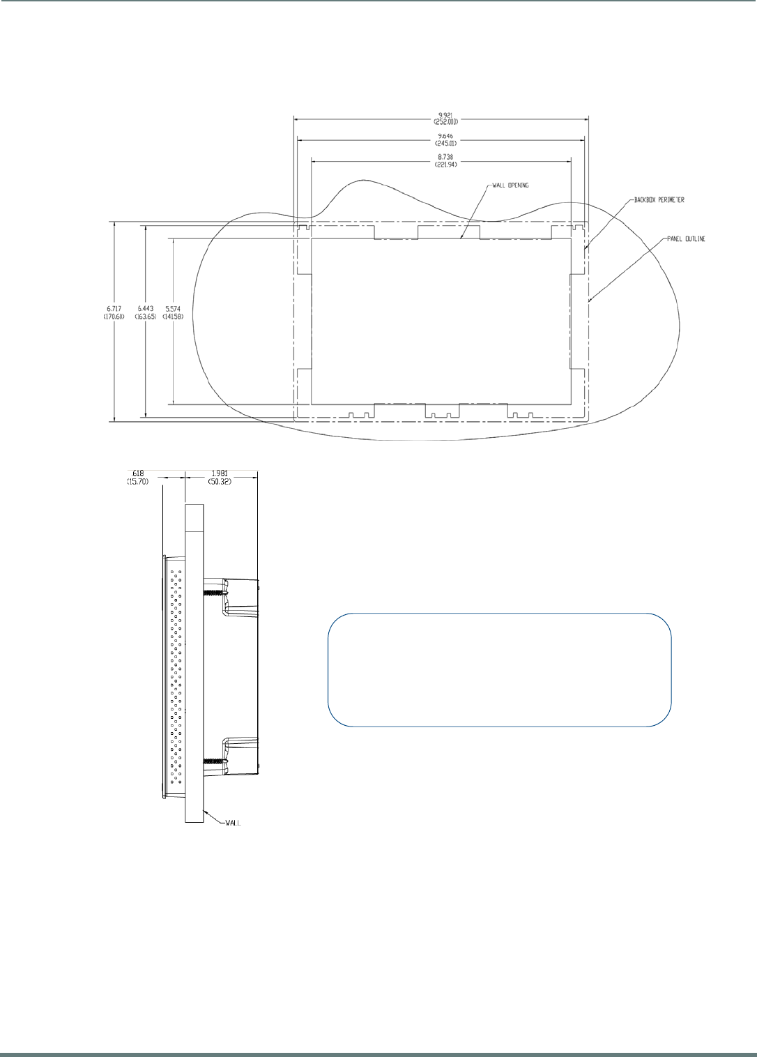
Installing Wall-Mount (MXD) Panels
46
Modero X® Series G5 Touch Panels - installation & Hardware Reference Manual
Installing the Backbox
MXD-1001 Installation Dimensions
FIG. 39 and FIG. 40 provide installation dimensions for the MXD-1001:
FIG. 39 MXD-1001 Installation Dimensions (front view)
FIG. 40 MXD-1001 Installation Dimensions (side view)
Notes:
- Dimensions in parenthesis are in millimeters.
- These drawings show a Landscape panel. The dimensions
are the same for Portrait panels, except for the vertical orientation.
Additional detailed installation and product drawings (for both
Landscape and Portrait panels) are available to view/download
at www.amx.com
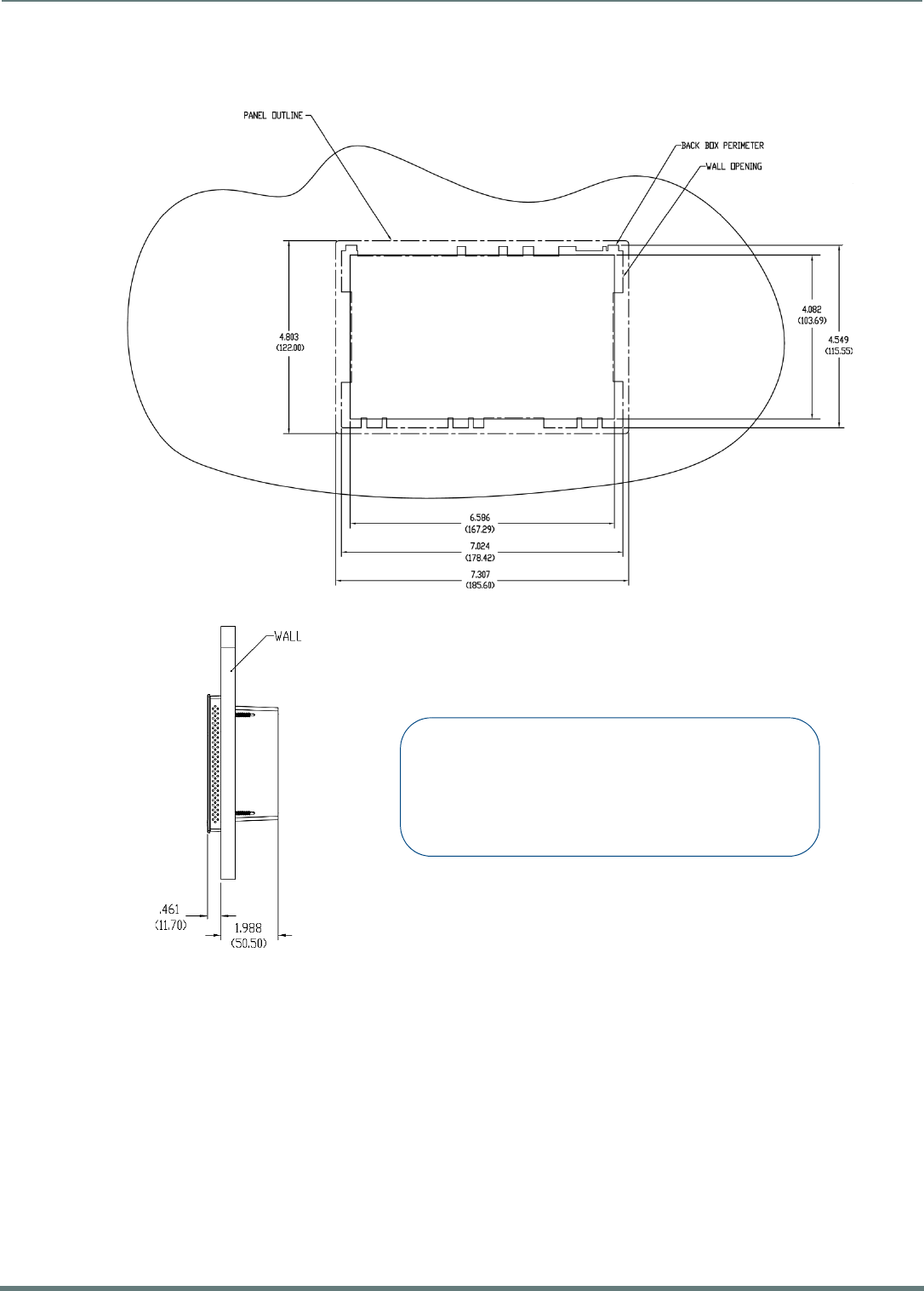
Installing Wall-Mount (MXD) Panels
47
Modero X® Series G5 Touch Panels - installation & Hardware Reference Manual
MXD-701 Installation Dimensions
FIG. 41 and FIG. 42 provide installation dimensions for the MXD-701:
Use the included Installation Template to ensure proper placement.
NOTE: Using the Installation Template to select the f inal placement of the Backbox is highly recommended. The outside edges of the
template are the same dimensions as the touch panel, which allows you to troubleshoot possible conflicts with wall edges, doors, and
other potential obstacles.
The MXD-1001 uses Installation Template 68-5968-03
The MXD-701 uses Installation Template 68-5968-04
1. Prepare the area by removing any screws or nails from the drywall before beginning the cutout process.
2. After ensuring proper placement, cut out the mounting surface for the Backbox, using the included Installation Template as a
guide.
NOTE: Making sure the actual cutout opening is slightly smaller than the provided dimensions is highly recommended. This
provides a margin for error if the opening needs to be expanded. Too little wall material removed is always better than too much.
FIG. 41 MXD-701-L Installation Dimensions (front view)
FIG. 42 MXD-701 Installation Dimensions (side view)
Notes:
- Dimensions in parenthesis are in millimeters.
- These drawings show a Landscape panel. The dimensions
are the same for Portrait panels, except for the vertical orientation.
Additional detailed installation and product drawings (for both
Landscape and Portrait panels) are available to view/download
at www.amx.com
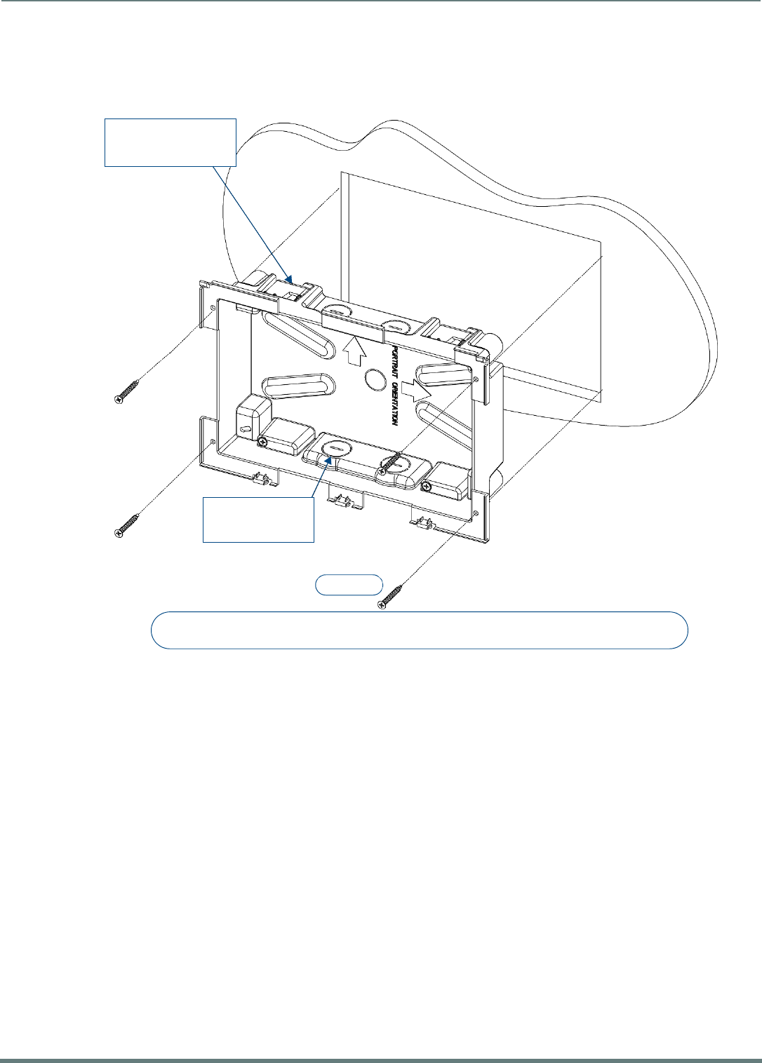
Installing Wall-Mount (MXD) Panels
48
Modero X® Series G5 Touch Panels - installation & Hardware Reference Manual
3. Thread the incoming Ethernet and USB cables through the surface opening (FIG. 43 and FIG. 44). Note that these figures
show a landscape panel but the installation of a portrait panel is essentially the same, other than the vertical orientation.
Leave enough slack in the wiring to accommodate any re-positioning of the panel.
FIG. 43 shows the MXD-1001 Backbox installation:
FIG. 43 MXD-1001 Backbox Installation (Landscape)
#4 Screws
4X Knock-Outs
Remove for Cable
Routing as Needed
4X Installation Clamp
for Wall Thickness
.31 [12.0] to .98 [.25.0]
Note:
Additional detailed installation and product drawings are available to view/download at www.amx.com
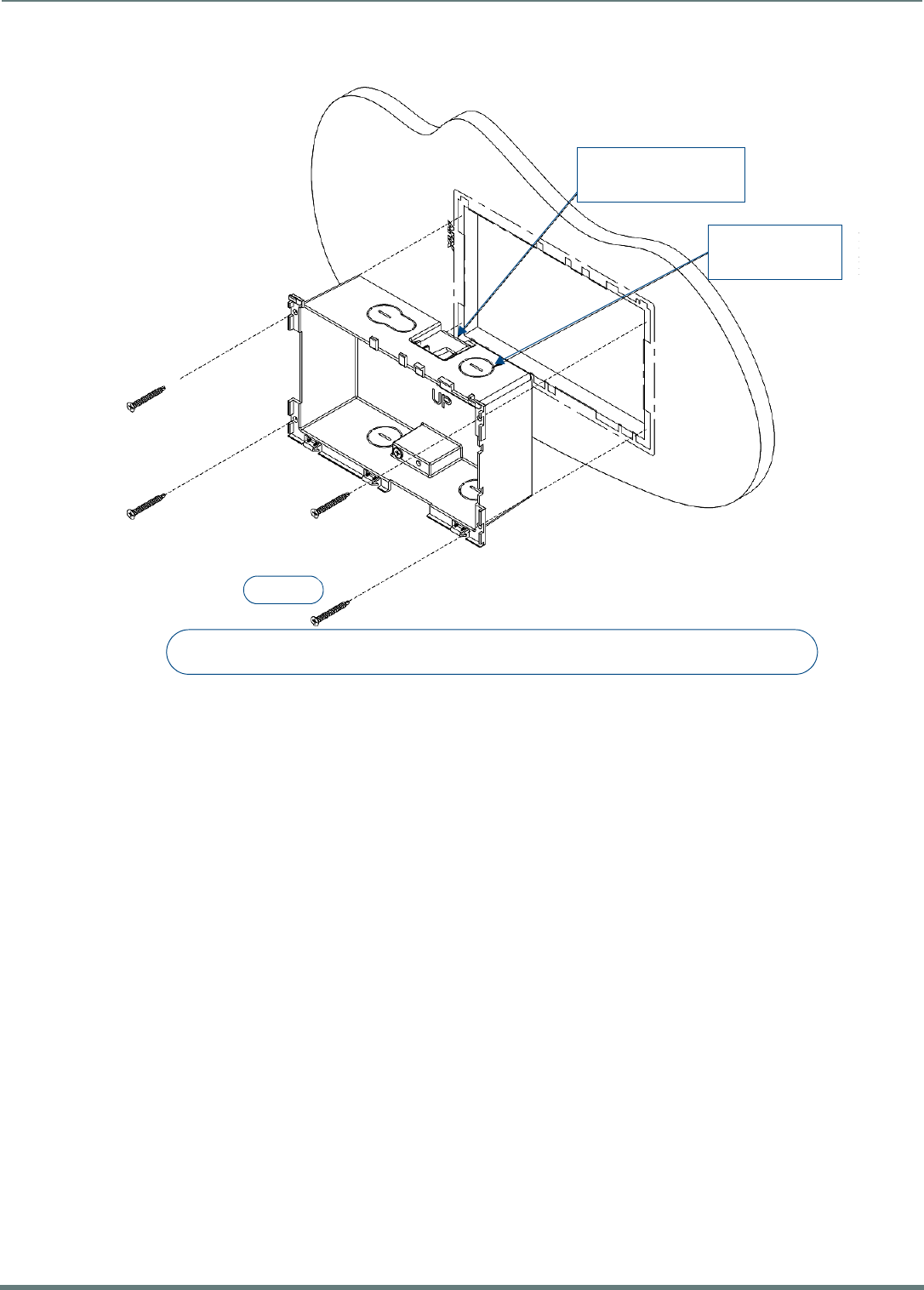
Installing Wall-Mount (MXD) Panels
49
Modero X® Series G5 Touch Panels - installation & Hardware Reference Manual
FIG. 44 shows the MXD-701 Backbox installation:
4. Remove any knockouts as needed on either long dimension of the Backbox to facilitate incoming wiring and pull the wiring
through the resultant holes.
5. Push the Backbox into the mounting surface. Insure that the locking tabs lie flush against the Backbox and that the Backbox
goes freely into the opening.
6. Extend the locking tabs on the sides of the Backbox by tightening the screws inside the box until snug.
NOTE: The maximum recommended torque to screw in the locking tabs on the plastic Backbox is 5 IN-LB [56 N-CM]. Applying
excessive torque while tightening the tab screws, such as with powered screwdrivers, can strip out the locking tabs or damage
the plastic Backbox.
Not all of the tabs must be extended to lock the Backbox in place, but extending a minimum of the top and bottom tabs is
highly recommended.
Apply enough pressure to the screw head to keep the box flush with the wall: this ensures that the locking tabs will tighten
up against the inside of the wall.
The Backbox is clear to allow visual confirmation that the tabs have been extended and are gripping the wall, as well as in
assisting with removal if necessary.
For additional strength, #4 mounting screws (not included) may be secured through circular holes located at the left and
right sides of the panel (FIG. 43, FIG. 44). In order to prevent damage to the touch panel, make sure that these are flush
with the Backbox.
7. Insert each connector into its corresponding location along the back of the panel.
a. To reach the RJ45 connector, gently pull it from beneath the electronics cover.
b. Attach the Ethernet cable and gently push the connection back under the cover.
NOTE: Refer to the Power via PoE section on page 50 for details on PoE and Ethernet Cable Installation and Modif ication.
8. Test the incoming wiring by attaching the panel connections to their terminal locations and applying power. Verify that the
panel is receiving power and functioning properly to prevent repetition of the installation.
NOTE: Do not disconnect the connectors from the touch panel. The unit must be installed with the attached connectors before
being inserted into the mounting surface.
9. Latch the panel onto the hooks on the Backbox. Push in on the bottom snaps (Landscape) or on the right (Portrait) gently but
firmly until the snaps “click” to lock it down (FIG. 45).
FIG. 44 MXD-701 Backbox Installation (Landscape)
#4 Screws
4X Knock-Outs
Remove for Cable
Routing as Needed
2X Installation Clamp
for Wall Thickness
.37 [12.03] to .98 [.25.0]
Note:
Additional detailed installation and product drawings are available to view/download at www.amx.com
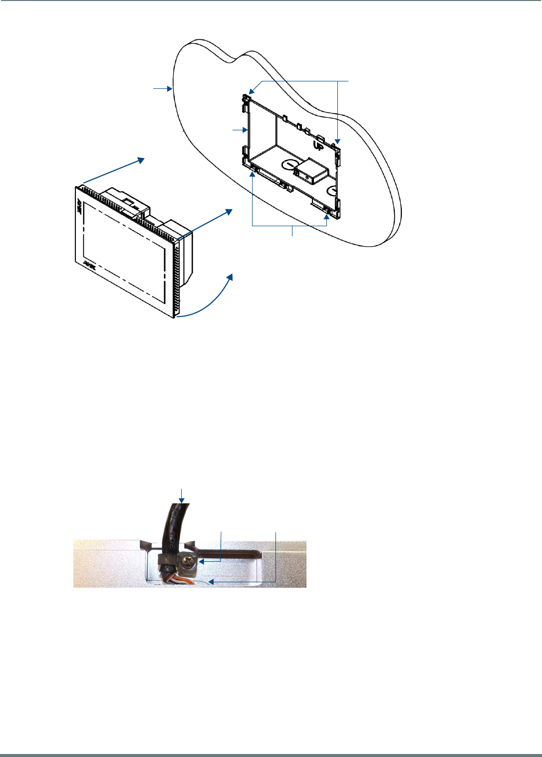
Installing Wall-Mount (MXD) Panels
50
Modero X® Series G5 Touch Panels - installation & Hardware Reference Manual
NOTE: If a gap is observed between the panel and the Backbox, or feel any binding while locking down the panel, stop
immediately and verify that no cables or other items are in the way. Do not force the panel into position, as this can cause
damage to the touch screen or the panel electronics.
10. Reconnect the terminal Ethernet and USB cables to their respective ports.
Power via PoE
Power for the MXD-1001 and MXD-701 is supplied via PoE (Power Over Ethernet ), utilizing an AMX-certified, capacitive touch-
compliant PoE injector such as the PS-POE-AT High Power PoE Injector (FG423-81) or other approved AMX PoE power source.
The incoming Ethernet cable should be connected to the RJ45 port on the cable attached to the device.
Ethernet Cable Installation and Modification
In tabletop installations where concealing the Ethernet cable is desired, a hole at least 1.00” (2.54 cm) in diameter is required in
the surface to allow passage of the female RJ45 connector (FIG. 46). If using a smaller hole is unavoidable, you will need to
disconnect the Ethernet cable (ECA5968-05) from the device, to feed the male end of the cable through.
NOTE: The minimum diameter hole through which the Ethernet cable may pass is 0.50" (1.27 cm).
To disconnect and reconnect the Ethernet cable on the MXT-701 and MXT-1001to allow use of a hole smaller than 1.00” in
diameter:
1. On a soft surface, turn the MXT-1001 face-down to access the bottom of the device.
2. Remove the clamp holding the Ethernet cable (FIG. 46).
3. Remove the Ethernet cable connector and pull the cable out of the clamp.
4. Pass the Ethernet cable (ECA5968-05) through the hole, with the RJ45 connector on the other side of the installation surface
from the device.
5. Press the Ethernet cable back into the clamp.
Do NOT tighten the clamp at this time.
FIG. 45 Installing the MXD-1001 / MXD-701
FIG. 46 Bottom of the MXT-701/1001
Mounting Surface
Backbox
Latch Hooks
Snaps
Ethernet Cable
Connector
Clamp
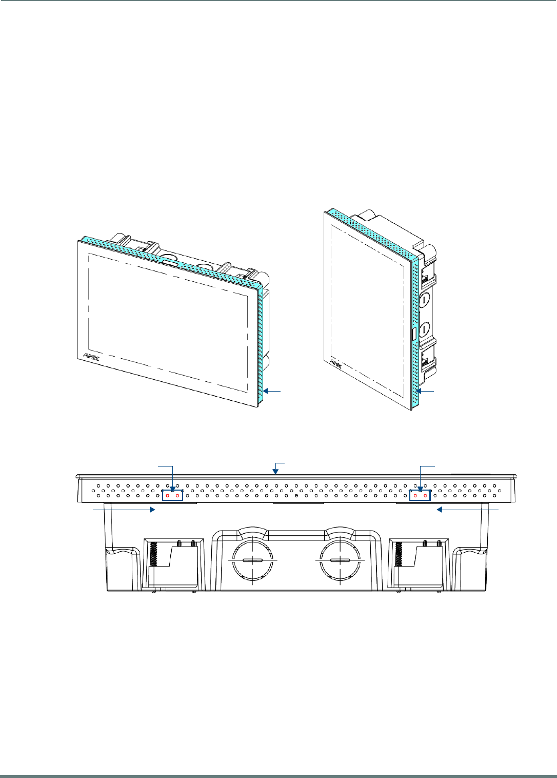
Installing Wall-Mount (MXD) Panels
51
Modero X® Series G5 Touch Panels - installation & Hardware Reference Manual
6. Using a non-conductive item such as a wooden stick, reinsert the Ethernet cable connector into the device. Ensure that the
connector is properly seated.
7. Tighten the clamp to secure the Ethernet cable.
Make sure the clamp is around the bundled black cable, not the individual wires.
8. Connect the RJ45 connector to its incoming Ethernet cable and apply power.
Uninstalling the MXD-1001
The MXD-1001 is held in place via latch hooks and clips in the Backbox.
In certain circumstances, such as firmware updates or other maintenance that requires accessing the device’s USB or Micro-USB
ports, the device may need to be removed from the Backbox.
The clips that lock down the MXD-1001’s bottom edge (Landscape) or right edge (Portrait) may be unlatched in order to remove
the device from the mounting surface.
Removing the MXD-1001 From Its Backbox
1. The MXD-1001 has three rows of ventilation holes along the molding (FIG. 47):
2. On the bottom (Landscape) or right side (Portrait) of the MXD-1001, locate the seventh and eight ventilation holes from each
edge, on the row closest to the Backbox (FIG. 48):.
3. With a stout, strong point (i.e. push pin or straightened paper clip), carefully press into the access holes in either end of the
molding until the snap is disconnected.
To facilitate the disconnection, grasp the bottom of the panel (Landscape) or right side (Portrait) and pull gently outward until
the side of the panel is free of the snap. Use your other hand to hold stable the front of the touch panel.
NOTE: Always pull on the frame of the touch panel. NEVER pull on the glass edge.
4. When the first side is free, repeat the process with the other.
5. With the edge of the touch panel free, carefully lift up and out (Landscape) or to the left and out (Portrait) to remove the touch
panel from the Backbox. Be careful not to pull on the cables or connectors.
6. To reattach the panel to its Backbox, repeat the installation procedure.
NOTE: For further information, refer to the video available at www.amx.com (go to Newsroom > Videos > Touch Panels).
FIG. 47 MXD-1001 Molding (highlighted in blue)
FIG. 48 Bottom View (Landscape) or Right-Side View (Portrait) of the MXD-1001 showing access holes in molding
Molding Molding
Access holes Access holes
Panel (surface)
#7, #8 #8, #7
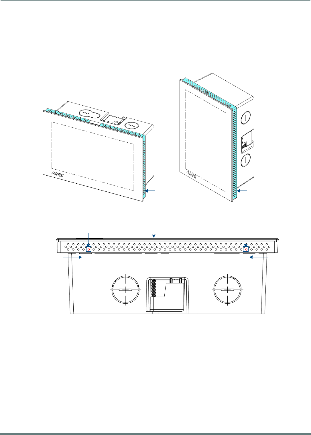
Installing Wall-Mount (MXD) Panels
52
Modero X® Series G5 Touch Panels - installation & Hardware Reference Manual
Uninstalling the MXD-701
The MXD-701 is held in place to the Backbox via latch hooks and clips on the Backbox.
In certain circumstances, such as firmware updates or other maintenance that requires accessing the device’s USB port, the device
may need to be removed from the Backbox. The clips that lock down the MXD-701’s bottom edge (Landscape) or right edge
(Portrait) may be unlatched in order to remove the device from the mounting surface.
Removing the MXD-701 From Its Backbox
1. The MXD-701 has three rows of ventilation holes along the molding (FIG. 47):
2. On the bottom (Landscape) or right side (Portrait) of the MXD-701, locate the fifth ventilation holes from each edge, on the
row closest to the Backbox (FIG. 48):.
3. With a stout, strong point (a push pin or straightened paper-clip, for example), carefully press into the access holes in either
end of the molding until the snap is disconnected.
To facilitate the disconnection, grasp the bottom of the panel (Landscape) or right side (Portrait) and pull gently outward until
the side of the panel is free of the snap. Use your other hand to hold stable the front of the touch panel.
NOTE: Always pull on the frame of the touch panel. NEVER pull on the glass edge.
4. When the first side is free, repeat the process with the other.
5. With the edge of the touch panel free, carefully lift up and out (Landscape) or to the left and out (Portrait) to remove the touch
panel from the Backbox. Be careful not to pull on the cables or connectors.
6. To reattach the panel to its Backbox, repeat the installation procedure.
NOTE: For further information, refer to the video available at www.amx.com (go to Newsroom > Videos > Touch Panels).
FIG. 49 MXD-701 Molding (highlighted in blue)
FIG. 50 Bottom View (Landscape) or Right-Side View (Portrait) of the MXD-701 showing access holes in molding
Molding Molding
Access hole Access hole
Panel (surface)
#5 #5

Appendix: Troubleshooting
53
Modero X® Series G5 Touch Panels - installation & Hardware Reference Manual
Appendix: Troubleshooting
Overview
This section describes the solutions to possible hardware/firmware issues that could arise during the common operation of a
Modero X Series G5 touch panel.
Panel Doesn’t Respond To Touches
Symptom: The device either does not respond to touches on the touch screen or does not register the touch as being in the correct
area of the screen.
If the screen is off:
The device may be in Display Sleep Mode. Press and hold the Sleep button to wake up the panel.
The device may not be connected to power. Verify that the power source is connected to the device and receiving power.
Panel Isn’t Appearing In The Online Tree Tab
1. Verify that the System number is the same on both the NetLinx Studio Project Navigator window and the System Settings page
on the device.
2. Verify the proper NetLinx Master IP and connection methods entered into the Master Connection section of the System
Settings page.
Can’t Connect To a NetLinx Master
Symptom: I can’t seem to connect to a NetLinx Master using NetLinx Studio.
Select Settings > Master Comm Settings > Communication Settings > Settings (for TCP/IP), and uncheck the "Automatically Ping
the Master Controller to ensure availability".
The pinging is to determine if the Master is available and to reply with a connection failure instantly if it is not. Without using the
ping feature, a connection may still be attempted, but a failure will take longer to be recognized.
NOTE: If you are trying to connect to a Master controller that is behind a f irewall, you may have to uncheck this option. Most firewalls
will not allow ping requests to pass through for security reasons.
When connecting to a NetLinx Master controller via TCP/IP, the program will first try to ping the controller before attempting a
connection. Pinging a device is relatively fast and will determine if the device is off-line, or if the TCP/IP address that was entered
was incorrect.
If you decide not to ping for availability and the controller is off-line, or you have an incorrect TCP/IP address, the program will try
for 30-45 seconds to establish a connection.
Only One Modero Panel In My System Shows Up
Symptom: I have more than one Modero panel connected to my System Master and only one shows up.
Multiple NetLinx Compatible devices can be associated for use with a single Master. If the user does not assign a device number,
one will be assigned automatically to the panel. When using multiple panels, different Device Number values have to be assigned to
each panel.
1. Press and hold the Sleep button to open the Settings menu.
2. Select the NetLinx menu, enter 1988 into the on-screen Keypad’s password field, and press Done when finished.
3. Enter a Device Number value for the panel into the Device Number Keypad. The range is from 1 - 32000.

© 2015 Harman. All rights reserved. Modero X and Modero X Series, AMX, AV FOR AN IT WORLD, and HARMAN,
and their respective logos are registered trademarks of HARMAN. Oracle, Java and any other company or brand
name referenced may be trademarks/registered trademarks of their respective companies.
AMX does not assume responsibility for errors or omissions. AMX also reserves the right to alter specifications
without prior notice at any time.
The AMX Warranty and Return Policy and related documents can be viewed/downloaded at www.amx.com.
3000 RESEARCH DRIVE, RICHARDSON, TX 75082
AMX.com | 800.222.0193 | 469.624.8000 | +1.469.624.7400 | fax 469.624.7153
Last Revised:
7/09/2015