ARRIS Group 224762 ADSL2+802.11b/g Ethernet Modem User Manual Administrator s Handbook V7 7 4
ARRIS Group, Inc. ADSL2+802.11b/g Ethernet Modem Administrator s Handbook V7 7 4
Users Manual
Administrator’s
Handbook
Embedded Software Version 7.7.4
Motorola Netopia
®
2200, 3300 and 7000
Series Gateways

Administrator’s Handbook
Copyright
Copyright © 2007 by Motorola, Inc.
All rights reserved. No part of this publication may be reproduced in any form or by any means or used to
make any derivative work (such as translation, transformation or adaptation) without written permission
from Motorola, Inc.
Motorola reserves the right to revise this publication and to make changes in content from time to time
without obligation on the part of Motorola to provide notification of such revision or change. Motorola
provides this guide without warranty of any kind, either implied or expressed, including, but not limited to,
the implied warranties of merchantability and fitness for a particular purpose. Motorola may make
improvements or changes in the product(s) described in this manual at any time. MOTOROLA and the
Stylized M Logo are registered in the US Patent & Trademark Office. Microsoft, Windows, Windows Me,
and Windows NT are either trademarks or registered trademarks of Microsoft Corporation in the U.S and/or
other countries. Macintosh is a registered trademark of Apple, Inc. Firefox is a registered trademark of the
Mozilla Foundation. All other product or service names are the property of their respective owners.
Motorola, Inc.
6001 Shellmound Street
Emeryville, CA 94608
U.S.A.
Part Number
6161244-00-01
Copyright Acknowledgments
Because Motorola has included certain software source code in this product, Motorola includes the
following text required by the respective copyright holders:
Portions of this software are based in part on the work of the following:
Copyright (c) 1998-2005 The OpenSSL Project. All rights reserved.
Redistribution and use in source and binary forms, with or without modification, are permitted provided that the
following conditions are met:
1. Redistributions of source code must retain the above copyright notice, this list of conditions and the following
disclaimer.
2. Redistributions in binary form must reproduce the above copyright notice, this list of conditions and the following
disclaimer in the documentation and/or other materials provided with the distribution.
3. All advertising materials mentioning features or use of this software must display the following acknowledgment:
“This product includes software developed by the OpenSSL Project for use in the OpenSSL Toolkit.
(http://www.openssl.org/)”
4. The names “OpenSSL Toolkit” and “OpenSSL Project” must not be used to endorse or promote products derived
from this software without prior written permission. For written permission, please contact openssl-
core@openssl.org.
5. Products derived from this software may not be called “OpenSSL” nor may “OpenSSL” appear in their names
without prior written permission of the OpenSSL Project.
6. Redistributions of any form whatsoever must retain the following acknowledgment:
“This product includes software developed by the OpenSSL Project
for use in the OpenSSL Toolkit (http://www.openssl.org/)”
THIS SOFTWARE IS PROVIDED BY THE OpenSSL PROJECT ``AS IS'' AND ANY EXPRESSED OR IMPLIED
WARRANTIES, INCLUDING, BUT NOT LIMITED TO, THE IMPLIED WARRANTIES OF MERCHANTABILITY AND
FITNESS FOR A PARTICULAR PURPOSE ARE DISCLAIMED. IN NO EVENT SHALL THE OpenSSL PROJECT
OR ITS CONTRIBUTORS BE LIABLE FOR ANY DIRECT, INDIRECT, INCIDENTAL, SPECIAL, EXEMPLARY, OR
CONSEQUENTIAL DAMAGES (INCLUDING, BUT NOT LIMITED TO, PROCUREMENT OF SUBSTITUTE GOODS
OR SERVICES; LOSS OF USE, DATA, OR PROFITS; OR BUSINESS INTERRUPTION) HOWEVER CAUSED AND
ON ANY THEORY OF LIABILITY, WHETHER IN CONTRACT, STRICT LIABILITY, OR TORT (INCLUDING
NEGLIGENCE OR OTHERWISE) ARISING IN ANY WAY OUT OF THE USE OF THIS SOFTWARE, EVEN IF
ADVISED OF THE POSSIBILITY OF SUCH DAMAGE.
This product includes cryptographic software written by Eric Young (eay@cryptsoft.com).
This product includes software written by Tim Hudson (tjh@cryptsoft.com).
Original SSLeay License
/Copyright (C) 1995-1998 Eric Young (eay@cryptsoft.com)
All rights reserved.
This package is an SSL implementation written by Eric Young (eay@cryptsoft.com).
The implementation was written so as to conform with Netscape’s SSL.
This library is free for commercial and non-commercial use as long as the following conditions are adhered to. The
following conditions apply to all code found in this distribution, be it the RC4, RSA, lhash, DES, etc., code; not just the
SSL code. The SSL documentation included with this distribution is covered by the same copyright terms except that
the holder is Tim Hudson (tjh@cryptsoft.com).

Copyright remains Eric Young's, and as such any Copyright notices in the code are not to be removed. If this
package is used in a product, Eric Young should be given attribution as the author of the parts of the library
used. This can be in the form of a textual message at program startup or in documentation (online or textual)
provided with the package.
Redistribution and use in source and binary forms, with or without modification, are permitted provided that the
following conditions are met:
1. Redistributions of source code must retain the copyright notice, this list of conditions and the following
disclaimer.
2. Redistributions in binary form must reproduce the above copyright notice, this list of conditions and the
following disclaimer in the documentation and/or other materials provided with the distribution.
3. All advertising materials mentioning features or use of this software must display the following
acknowledgement:
“This product includes cryptographic software written by Eric Young (eay@cryptsoft.com)”
The word 'cryptographic' can be left out if the routines from the library being used are not cryptographic
related :-).
4. If you include any Windows specific code (or a derivative thereof) from the apps directory (application code)
you must include an acknowledgement:
“This product includes software written by Tim Hudson (tjh@cryptsoft.com)”
THIS SOFTWARE IS PROVIDED BY ERIC YOUNG ``AS IS'' AND ANY EXPRESS OR IMPLIED
WARRANTIES, INCLUDING, BUT NOT LIMITED TO, THE IMPLIED WARRANTIES OF MERCHANTABILITY
AND FITNESS FOR A PARTICULAR PURPOSE ARE DISCLAIMED. IN NO EVENT SHALL THE AUTHOR OR
CONTRIBUTORS BE LIABLE FOR ANY DIRECT, INDIRECT, INCIDENTAL, SPECIAL, EXEMPLARY, OR
CONSEQUENTIAL DAMAGES (INCLUDING, BUT NOT LIMITED TO, PROCUREMENT OF SUBSTITUTE
GOODS OR SERVICES; LOSS OF USE, DATA, OR PROFITS; OR BUSINESS INTERRUPTION) HOWEVER
CAUSED AND ON ANY THEORY OF LIABILITY, WHETHER IN CONTRACT, STRICT LIABILITY, OR TORT
(INCLUDING NEGLIGENCE OR OTHERWISE) ARISING IN ANY WAY OUT OF THE USE OF THIS
SOFTWARE, EVEN IF ADVISED OF THE POSSIBILITY OF SUCH DAMAGE.
The licence and distribution terms for any publicly available version or derivative of this code cannot be
changed. i.e. this code cannot simply be copied and put under another distribution licence [including the GNU
Public Licence.]
Portions of this software are based in part on the work of the following:
Copyright (C) 1995, 1996, 1997, and 1998 WIDE Project. All rights reserved.
Redistribution and use in source and binary forms, with or without modification, are permitted provided that the
following conditions are met:
1. Redistributions of source code must retain the above copyright notice, this list of conditions and the following
disclaimer.
2. Redistributions in binary form must reproduce the above copyright notice, this list of conditions and the
following disclaimer in the documentation and/or other materials provided with the distribution.
3. Neither the name of the project nor the names of its contributors may be used to endorse or promote
products derived from this software without specific prior written permission.
THIS SOFTWARE IS PROVIDED BY THE PROJECT AND CONTRIBUTORS ``AS IS'' AND ANY EXPRESS
OR IMPLIED WARRANTIES, INCLUDING, BUT NOT LIMITED TO, THE IMPLIED WARRANTIES OF
MERCHANTABILITY AND FITNESS FOR A PARTICULAR PURPOSE ARE DISCLAIMED. IN NO EVENT
SHALL THE PROJECT OR CONTRIBUTORS BE LIABLE FOR ANY DIRECT, INDIRECT, INCIDENTAL,
SPECIAL, EXEMPLARY, OR CONSEQUENTIAL DAMAGES (INCLUDING, BUT NOT LIMITED TO,
PROCUREMENT OF SUBSTITUTE GOODS OR SERVICES; LOSS OF USE, DATA, OR PROFITS; OR
BUSINESS INTERRUPTION) HOWEVER CAUSED AND ON ANY THEORY OF LIABILITY, WHETHER IN
CONTRACT, STRICT LIABILITY, OR TORT (INCLUDING NEGLIGENCE OR OTHERWISE) ARISING IN ANY
WAY OUT OF THE USE OF THIS SOFTWARE, EVEN IF ADVISED OF THE POSSIBILITY OF SUCH
DAMAGE.
Portions of this software are based in part on the work of the following:
Copyright (C) 1990, RSA Data Security, Inc. All rights reserved.
<<RSA Data Security, Inc. MD5 Message-Digest Algorithm>>
License to copy and use this software is granted provided that it is identified as the “RSA Data Security, Inc.
MD5 Message Digest Algorithm” in all material mentioning or referencing this software or this function.
License is also granted to make and use derivative works provided that such works are identified as “derived
from the RSA Data Security, Inc. MD5 Message-Digest Algorithm” in all material mentioning or referencing the
derived work.
<<RSA Data Security, Inc. MD4 Message-Digest Algorithm>>
License to copy and use this software is granted provided that it is identified as the “RSA Data Security, Inc.
MD4 Message Digest Algorithm” in all material mentioning or referencing this software or this function.
License is also granted to make and use derivative works provided that such works are identified as “derived
from the RSA Data Security, Inc. MD4 Message-Digest Algorithm” in all material mentioning or referencing the
derived work.

Administrator’s Handbook
RSA Data Security, Inc. makes no representations concerning either the merchantability of this software or the
suitability of this software for any particular purpose. It is provided “as is” without express or implied warranty of any
kind.
These notices must be retained in any copies of any part of this documentation and/or software.
Portions of this software are based in part on the work of the following:
Copyright (c) 1989 Carnegie Mellon University. All rights reserved.
Redistribution and use in source and binary forms are permitted provided that the above copyright notice and this
paragraph are duplicated in all such forms and that any documentation, advertising materials, and other materials
related to such distribution and use acknowledge that the software was developed by Carnegie Mellon University.
The name of the University may not be used to endorse or promote products derived from this software without
specific prior written permission.
THIS SOFTWARE IS PROVIDED ``AS IS'' AND WITHOUT ANY EXPRESS OR IMPLIED WARRANTIES,
INCLUDING, WITHOUT LIMITATION, THE IMPLIED WARRANTIES OF MERCHANTIBILITY AND FITNESS FOR A
PARTICULAR PURPOSE.
Portions of this software are based in part on the work of the following:
Copyright 2000, 2001 Shane Kerr. All rights reserved.
Redistribution and use in source and binary forms, with or without modification, are permitted provided that the
following conditions are met:
1. Redistributions of source code must retain the above copyright notice, this list of conditions and the following
disclaimer.
2. Redistributions in binary form must reproduce the above copyright notice, this list of conditions and the following
disclaimer in the documentation and/or other materials provided with the distribution.
THIS SOFTWARE IS PROVIDED BY THE AUTHOR(S) ``AS IS'' AND ANY EXPRESS OR IMPLIED WARRANTIES,
INCLUDING, BUT NOT LIMITED TO, THE IMPLIED WARRANTIES OF MERCHANTABILITY AND FITNESS FOR A
PARTICULAR PURPOSE ARE DISCLAIMED. IN NO EVENT SHALL THE REGENTS OR CONTRIBUTORS BE
LIABLE FOR ANY DIRECT, INDIRECT, INCIDENTAL, SPECIAL, EXEMPLARY, OR CONSEQUENTIAL DAMAGES
(INCLUDING, BUT NOT LIMITED TO, PROCUREMENT OF SUBSTITUTE GOODS OR SERVICES; LOSS OF USE,
DATA, OR PROFITS; OR BUSINESS INTERRUPTION) HOWEVER CAUSED AND ON ANY THEORY OF
LIABILITY, WHETHER IN CONTRACT, STRICT LIABILITY, OR TORT (INCLUDING NEGLIGENCE OR
OTHERWISE) ARISING IN ANY WAY OUT OF THE USE OF THIS SOFTWARE, EVEN IF ADVISED OF THE
POSSIBILITY OF SUCH DAMAGE.

5
Table of Contents
CHAPTER 1
Introduction . . . . . . . . . . . . . . . . . . . . . . . . . . . . . . . . . 13
What’s New in 7.7.4
. . . . . . . . . . . . . . . . . . . . . . . . . . . . . . . . 13
About Motorola Netopia® Documentation
. . . . . . . . . . . . . . . . 15
Intended Audience
. . . . . . . . . . . . . . . . . . . . . . . . . . . . . . . . . 15
Documentation Conventions
. . . . . . . . . . . . . . . . . . . . . . . . . . 15
General. . . . . . . . . . . . . . . . . . . . . . . . . . . . . . . . . . . . . . . . . . . . . . . . . 15
Internal Web Interface . . . . . . . . . . . . . . . . . . . . . . . . . . . . . . . . . . . . . 16
Command Line Interface . . . . . . . . . . . . . . . . . . . . . . . . . . . . . . . . . . . 16
Organization
. . . . . . . . . . . . . . . . . . . . . . . . . . . . . . . . . . . . . . 17
A Word About Example Screens
. . . . . . . . . . . . . . . . . . . . . . . 17
CHAPTER 2
Basic Mode Setup . . . . . . . . . . . . . . . . . . . . . . . . . . . . . 19
Important Safety Instructions
. . . . . . . . . . . . . . . . . . . . . . . . . . 20
POWER SUPPLY INSTALLATION. . . . . . . . . . . . . . . . . . . . . . . . . . . . 20
TELECOMMUNICATION INSTALLATION . . . . . . . . . . . . . . . . . . . . . . 20
PRODUCT VENTILATION . . . . . . . . . . . . . . . . . . . . . . . . . . . . . . . . . . 20
Wichtige Sicherheitshinweise
. . . . . . . . . . . . . . . . . . . . . . . . . 21
NETZTEIL INSTALLIEREN . . . . . . . . . . . . . . . . . . . . . . . . . . . . . . . . . 21
INSTALLATION DER TELEKOMMUNIKATION . . . . . . . . . . . . . . . . . . 21
Setting up the Motorola Netopia® Gateway
. . . . . . . . . . . . . . 22
Microsoft Windows: . . . . . . . . . . . . . . . . . . . . . . . . . . . . . . . . . . . 22
Macintosh MacOS 8 or higher or Mac OS X: . . . . . . . . . . . . . . . . 24
Configuring the Motorola Netopia® Gateway
. . . . . . . . . . . . . 25
MiAVo VDSL and Ethernet WAN models Quickstart . . . . . . . . . . . . . . 25
PPPoE Quickstart. . . . . . . . . . . . . . . . . . . . . . . . . . . . . . . . . . . . . . . . . 27
Set up the Motorola Netopia® Pocket Gateway. . . . . . . . . . . . . . . . . . 28
Motorola Netopia® Gateway Status Indicator Lights
. . . . . . . . 30
Home Page - Basic Mode
. . . . . . . . . . . . . . . . . . . . . . . . . . . . 31
Manage My Account. . . . . . . . . . . . . . . . . . . . . . . . . . . . . . . . . . . . . . . 33
Status Details . . . . . . . . . . . . . . . . . . . . . . . . . . . . . . . . . . . . . . . . . . . . 34
Enable Remote Management . . . . . . . . . . . . . . . . . . . . . . . . . . . . . . . 35
Expert Mode. . . . . . . . . . . . . . . . . . . . . . . . . . . . . . . . . . . . . . . . . . . . . 36
Update Firmware . . . . . . . . . . . . . . . . . . . . . . . . . . . . . . . . . . . . . . . . . 37
Factory Reset. . . . . . . . . . . . . . . . . . . . . . . . . . . . . . . . . . . . . . . . . . . . 38
CHAPTER 3
Expert Mode . . . . . . . . . . . . . . . . . . . . . . . . . . . . . . . . . 39
Accessing the Expert Web Interface
. . . . . . . . . . . . . . . . . . . . 39
Open the Web Connection. . . . . . . . . . . . . . . . . . . . . . . . . . . . . . . . . . 39
Home Page - Expert Mode. . . . . . . . . . . . . . . . . . . . . . . . . . . . . . . . . . 41

Administrator’s Handbook
6
Home Page - Information . . . . . . . . . . . . . . . . . . . . . . . . . . . . . . . . . . . 41
Toolbar
. . . . . . . . . . . . . . . . . . . . . . . . . . . . . . . . . . . . . . . . . . 43
Navigating the Web Interface
. . . . . . . . . . . . . . . . . . . . . . . . . 43
Breadcrumb Trail . . . . . . . . . . . . . . . . . . . . . . . . . . . . . . . . . . . . . . . . . 43
Restart
. . . . . . . . . . . . . . . . . . . . . . . . . . . . . . . . . . . . . . . . . . 44
Alert Symbol. . . . . . . . . . . . . . . . . . . . . . . . . . . . . . . . . . . . . . . . . . . . . 45
Help
. . . . . . . . . . . . . . . . . . . . . . . . . . . . . . . . . . . . . . . . . . . . 46
Configure
. . . . . . . . . . . . . . . . . . . . . . . . . . . . . . . . . . . . . . . . 47
Quickstart . . . . . . . . . . . . . . . . . . . . . . . . . . . . . . . . . . . . . . . . . . . . . . . 47
How to Use the Quickstart Page . . . . . . . . . . . . . . . . . . . . . . . . . 47
Setup Your Gateway using a PPP Connection . . . . . . . . . . . . . . 47
LAN . . . . . . . . . . . . . . . . . . . . . . . . . . . . . . . . . . . . . . . . . . . . . . . . . . . 49
Wireless . . . . . . . . . . . . . . . . . . . . . . . . . . . . . . . . . . . . . . . . . . . . . . . . 53
Privacy . . . . . . . . . . . . . . . . . . . . . . . . . . . . . . . . . . . . . . . . . . . . . . . . . 54
Advanced . . . . . . . . . . . . . . . . . . . . . . . . . . . . . . . . . . . . . . . . . . . . . . . 56
About Closed System Mode . . . . . . . . . . . . . . . . . . . . . . . . . . . . . 57
WPA Version Allowed . . . . . . . . . . . . . . . . . . . . . . . . . . . . . . . . . . 59
Multiple SSIDs . . . . . . . . . . . . . . . . . . . . . . . . . . . . . . . . . . . . . . . . . . . 59
WiFi Multimedia . . . . . . . . . . . . . . . . . . . . . . . . . . . . . . . . . . . . . . . . . . 62
Wireless MAC Authorization. . . . . . . . . . . . . . . . . . . . . . . . . . . . . . . . . 63
Use RADIUS Server . . . . . . . . . . . . . . . . . . . . . . . . . . . . . . . . . . . 65
WAN. . . . . . . . . . . . . . . . . . . . . . . . . . . . . . . . . . . . . . . . . . . . . . . . . . . 67
PPP over Ethernet interface. . . . . . . . . . . . . . . . . . . . . . . . . . . . . . . . . 67
Advanced: . . . . . . . . . . . . . . . . . . . . . . . . . . . . . . . . . . . . . . . . . . . 69
Ethernet WAN interface . . . . . . . . . . . . . . . . . . . . . . . . . . . . . . . . . . . . 70
WAN Ethernet and VDSL Gateways. . . . . . . . . . . . . . . . . . . . . . . 73
ADSL Gateways . . . . . . . . . . . . . . . . . . . . . . . . . . . . . . . . . . . . . . 73
Advanced . . . . . . . . . . . . . . . . . . . . . . . . . . . . . . . . . . . . . . . . . . . . . . . 78
IP Static Routes . . . . . . . . . . . . . . . . . . . . . . . . . . . . . . . . . . . . . . . . . . 79
IP Static ARP . . . . . . . . . . . . . . . . . . . . . . . . . . . . . . . . . . . . . . . . . . . . 81
Pinholes . . . . . . . . . . . . . . . . . . . . . . . . . . . . . . . . . . . . . . . . . . . . . . . . 82
Configure Specific Pinholes . . . . . . . . . . . . . . . . . . . . . . . . . . . . . 82
Planning for Your Pinholes . . . . . . . . . . . . . . . . . . . . . . . . . . . . . 82
Example: A LAN Requiring Three Pinholes . . . . . . . . . . . . . . . . . 82
Pinhole Configuration Procedure . . . . . . . . . . . . . . . . . . . . . . . . . 84
IPMaps . . . . . . . . . . . . . . . . . . . . . . . . . . . . . . . . . . . . . . . . . . . . . . . . . 87
Configure the IPMaps Feature . . . . . . . . . . . . . . . . . . . . . . . . . . . . . . . 87
FAQs for the IPMaps Feature . . . . . . . . . . . . . . . . . . . . . . . . . . . . 87
What are IPMaps and how are they used? . . . . . . . . . . . . . . . . . 87
What types of servers are supported by IPMaps? . . . . . . . . . . . . 87
Can I use IPMaps with my PPPoE or PPPoA connection? . . . . . 87
Will IPMaps allow IP addresses from different subnets to be assigned to my Gate-
way? . . . . . . . . . . . . . . . . . . . . . . . . . . . . . . . . . . . . . . . . . . . . . . . 87
IPMaps Block Diagram . . . . . . . . . . . . . . . . . . . . . . . . . . . . . . . . . 88
Default Server . . . . . . . . . . . . . . . . . . . . . . . . . . . . . . . . . . . . . . . . . . . 89
Configure a Default Server . . . . . . . . . . . . . . . . . . . . . . . . . . . . . . 89
Typical Network Diagram . . . . . . . . . . . . . . . . . . . . . . . . . . . . . . . 89
NAT Combination Application . . . . . . . . . . . . . . . . . . . . . . . . . . . 90
IP-Passthrough . . . . . . . . . . . . . . . . . . . . . . . . . . . . . . . . . . . . . . 90
A restriction . . . . . . . . . . . . . . . . . . . . . . . . . . . . . . . . . . . . . . . . . 91
Differentiated Services . . . . . . . . . . . . . . . . . . . . . . . . . . . . . . . . . . . . . 92
DNS . . . . . . . . . . . . . . . . . . . . . . . . . . . . . . . . . . . . . . . . . . . . . . . . . . . 95
DHCP Server . . . . . . . . . . . . . . . . . . . . . . . . . . . . . . . . . . . . . . . . . . . . 96
RADIUS Server . . . . . . . . . . . . . . . . . . . . . . . . . . . . . . . . . . . . . . . . . . 97

7
SNMP. . . . . . . . . . . . . . . . . . . . . . . . . . . . . . . . . . . . . . . . . . . . . . . . . . 98
IGMP (Internet Group Management Protocol) . . . . . . . . . . . . . . . . . . 100
UPnP . . . . . . . . . . . . . . . . . . . . . . . . . . . . . . . . . . . . . . . . . . . . . . . . . 102
LAN Management . . . . . . . . . . . . . . . . . . . . . . . . . . . . . . . . . . . . . . . 103
Ethernet Bridge . . . . . . . . . . . . . . . . . . . . . . . . . . . . . . . . . . . . . . . . . 104
Configuring for Bridge Mode . . . . . . . . . . . . . . . . . . . . . . . . . . . . . . . 105
VLAN . . . . . . . . . . . . . . . . . . . . . . . . . . . . . . . . . . . . . . . . . . . . . . . . . 107
Overview . . . . . . . . . . . . . . . . . . . . . . . . . . . . . . . . . . . . . . . . . . . . . . 107
Ethernet Switching/Policy Setup . . . . . . . . . . . . . . . . . . . . . . . . . . . . 108
Example . . . . . . . . . . . . . . . . . . . . . . . . . . . . . . . . . . . . . . . . . . . 116
VoIP . . . . . . . . . . . . . . . . . . . . . . . . . . . . . . . . . . . . . . . . . . . . . . . . . . 120
System . . . . . . . . . . . . . . . . . . . . . . . . . . . . . . . . . . . . . . . . . . . . . . . . 124
Syslog Parameters. . . . . . . . . . . . . . . . . . . . . . . . . . . . . . . . . . . . . . . 125
Log Event Messages . . . . . . . . . . . . . . . . . . . . . . . . . . . . . . . . . . . . . 126
Internal Servers . . . . . . . . . . . . . . . . . . . . . . . . . . . . . . . . . . . . . . . . . 129
Software Hosting . . . . . . . . . . . . . . . . . . . . . . . . . . . . . . . . . . . . . . . . 130
List of Supported Games and Software . . . . . . . . . . . . . . . . . . . 131
Rename a User(PC). . . . . . . . . . . . . . . . . . . . . . . . . . . . . . . . . . . . . . 132
Backup . . . . . . . . . . . . . . . . . . . . . . . . . . . . . . . . . . . . . . . . . . . . . . . . 133
Manual options . . . . . . . . . . . . . . . . . . . . . . . . . . . . . . . . . . . . . . 133
Automatic options . . . . . . . . . . . . . . . . . . . . . . . . . . . . . . . . . . . . 134
Ethernet MAC Override . . . . . . . . . . . . . . . . . . . . . . . . . . . . . . . . . . . 136
Clear Options . . . . . . . . . . . . . . . . . . . . . . . . . . . . . . . . . . . . . . . . . . . 137
Time Zone . . . . . . . . . . . . . . . . . . . . . . . . . . . . . . . . . . . . . . . . . . . . . 138
Security
. . . . . . . . . . . . . . . . . . . . . . . . . . . . . . . . . . . . . . . . . 139
Passwords . . . . . . . . . . . . . . . . . . . . . . . . . . . . . . . . . . . . . . . . . . . . . 140
Create and Change Passwords . . . . . . . . . . . . . . . . . . . . . . . . . 140
Firewall. . . . . . . . . . . . . . . . . . . . . . . . . . . . . . . . . . . . . . . . . . . . . . . . 142
Use a Motorola Netopia® Firewall . . . . . . . . . . . . . . . . . . . . . . . 142
BreakWater Basic Firewall . . . . . . . . . . . . . . . . . . . . . . . . . . . . . 142
Configuring for a BreakWater Setting . . . . . . . . . . . . . . . . . . . . . 142
TIPS for making your BreakWater Basic Firewall Selection . . . 143
Basic Firewall Background . . . . . . . . . . . . . . . . . . . . . . . . . . . . . 143
IPSec . . . . . . . . . . . . . . . . . . . . . . . . . . . . . . . . . . . . . . . . . . . . . . . . . 146
SafeHarbour IPSec VPN . . . . . . . . . . . . . . . . . . . . . . . . . . . . . . . . . . 147
Configuring a SafeHarbour VPN. . . . . . . . . . . . . . . . . . . . . . . . . 148
Parameter Descriptions. . . . . . . . . . . . . . . . . . . . . . . . . . . . . . . . 151
Stateful Inspection . . . . . . . . . . . . . . . . . . . . . . . . . . . . . . . . . . . . . . . 154
Stateful Inspection Firewall installation procedure . . . . . . . . . . . . . . . 154
Exposed Addresses . . . . . . . . . . . . . . . . . . . . . . . . . . . . . . . . . . . . . . 155
Stateful Inspection Options . . . . . . . . . . . . . . . . . . . . . . . . . . . . . . . . 157
Open Ports in Default Stateful Inspection Installation . . . . . . . . . . . . 157
Firewall Tutorial
. . . . . . . . . . . . . . . . . . . . . . . . . . . . . . . . . . . 158
General firewall terms . . . . . . . . . . . . . . . . . . . . . . . . . . . . . . . . . . . . 158
Basic IP packet components . . . . . . . . . . . . . . . . . . . . . . . . . . . . . . . 158
Basic protocol types . . . . . . . . . . . . . . . . . . . . . . . . . . . . . . . . . . . . . . 158
Firewall design rules. . . . . . . . . . . . . . . . . . . . . . . . . . . . . . . . . . . . . . 159
Firewall Logic . . . . . . . . . . . . . . . . . . . . . . . . . . . . . . . . . . . . . . . 159
Implied rules . . . . . . . . . . . . . . . . . . . . . . . . . . . . . . . . . . . . . . . . 160
Example filter set page . . . . . . . . . . . . . . . . . . . . . . . . . . . . . . . . 160
Filter basics . . . . . . . . . . . . . . . . . . . . . . . . . . . . . . . . . . . . . . . . . . . . 161
Example network. . . . . . . . . . . . . . . . . . . . . . . . . . . . . . . . . . . . . 161
Example filters . . . . . . . . . . . . . . . . . . . . . . . . . . . . . . . . . . . . . . . . . . 161
Example 1 . . . . . . . . . . . . . . . . . . . . . . . . . . . . . . . . . . . . . . . . . 161
Example 2 . . . . . . . . . . . . . . . . . . . . . . . . . . . . . . . . . . . . . . . . . 162

Administrator’s Handbook
8
Example 3 . . . . . . . . . . . . . . . . . . . . . . . . . . . . . . . . . . . . . . . . . . 162
Example 4 . . . . . . . . . . . . . . . . . . . . . . . . . . . . . . . . . . . . . . . . . . 162
Example 5 . . . . . . . . . . . . . . . . . . . . . . . . . . . . . . . . . . . . . . . . . . 162
Packet Filter . . . . . . . . . . . . . . . . . . . . . . . . . . . . . . . . . . . . . . . . . . . . 163
What’s a filter and what’s a filter set?. . . . . . . . . . . . . . . . . . . . . . . . . 163
How filter sets work . . . . . . . . . . . . . . . . . . . . . . . . . . . . . . . . . . . . . . 164
Filter priority . . . . . . . . . . . . . . . . . . . . . . . . . . . . . . . . . . . . . . . . 164
How individual filters work . . . . . . . . . . . . . . . . . . . . . . . . . . . . . . . . . 165
A filtering rule . . . . . . . . . . . . . . . . . . . . . . . . . . . . . . . . . . . . . . . 165
Parts of a filter. . . . . . . . . . . . . . . . . . . . . . . . . . . . . . . . . . . . . . . 165
Port numbers. . . . . . . . . . . . . . . . . . . . . . . . . . . . . . . . . . . . . . . . 165
Port number comparisons. . . . . . . . . . . . . . . . . . . . . . . . . . . . . . 166
Other filter attributes . . . . . . . . . . . . . . . . . . . . . . . . . . . . . . . . . . 166
Putting the parts together . . . . . . . . . . . . . . . . . . . . . . . . . . . . . . 167
Filtering example #1 . . . . . . . . . . . . . . . . . . . . . . . . . . . . . . . . . . 167
Filtering example #2 . . . . . . . . . . . . . . . . . . . . . . . . . . . . . . . . . . 169
Design guidelines. . . . . . . . . . . . . . . . . . . . . . . . . . . . . . . . . . . . . . . . 169
An approach to using filters. . . . . . . . . . . . . . . . . . . . . . . . . . . . . 170
Working with IP Filters and Filter Sets
. . . . . . . . . . . . . . . . . . 171
Adding a filter set . . . . . . . . . . . . . . . . . . . . . . . . . . . . . . . . . . . . . . . . 171
Adding filters to a filter set . . . . . . . . . . . . . . . . . . . . . . . . . . . . . . . . . 172
Viewing filters . . . . . . . . . . . . . . . . . . . . . . . . . . . . . . . . . . . . . . . 175
Modifying filters . . . . . . . . . . . . . . . . . . . . . . . . . . . . . . . . . . . . . . 175
Deleting filters . . . . . . . . . . . . . . . . . . . . . . . . . . . . . . . . . . . . . . . 175
Moving filters. . . . . . . . . . . . . . . . . . . . . . . . . . . . . . . . . . . . . . . . 175
Deleting a filter set . . . . . . . . . . . . . . . . . . . . . . . . . . . . . . . . . . . . . . . 175
Associating a Filter Set with an Interface
. . . . . . . . . . . . . . . 176
Policy-based Routing using Filtersets
. . . . . . . . . . . . . . . . . . 177
TOS field matching. . . . . . . . . . . . . . . . . . . . . . . . . . . . . . . . . . . . . . . 177
Security Log . . . . . . . . . . . . . . . . . . . . . . . . . . . . . . . . . . . . . . . . . . . . 179
Using the Security Monitoring Log . . . . . . . . . . . . . . . . . . . . . . . 179
Timestamp Background . . . . . . . . . . . . . . . . . . . . . . . . . . . . . . . 181
Install
. . . . . . . . . . . . . . . . . . . . . . . . . . . . . . . . . . . . . . . . . . . 182
Install Software. . . . . . . . . . . . . . . . . . . . . . . . . . . . . . . . . . . . . . . . . . 183
Updating Your Gateway’s Motorola Netopia® Firmware Version 183
Step 1: Required Files . . . . . . . . . . . . . . . . . . . . . . . . . . . . . . . . . . . . 183
Step 2: Motorola Netopia® firmware Image File . . . . . . . . . . . . . . . . 184
Install Key. . . . . . . . . . . . . . . . . . . . . . . . . . . . . . . . . . . . . . . . . . . . . . 187
Use Motorola Netopia® Software Feature Keys . . . . . . . . . . . . . . . . 187
Obtaining Software Feature Keys . . . . . . . . . . . . . . . . . . . . . . . . 187
Procedure - Install a New Feature Key File . . . . . . . . . . . . . . . . 187
To check your installed features: . . . . . . . . . . . . . . . . . . . . . . . . 189
Install Certificate. . . . . . . . . . . . . . . . . . . . . . . . . . . . . . . . . . . . . . . . . 190
CHAPTER 4
Basic Troubleshooting . . . . . . . . . . . . . . . . . . . . . . . . 193
Status Indicator Lights
. . . . . . . . . . . . . . . . . . . . . . . . . . . . . . 194
LED Function Summary Matrix . . . . . . . . . . . . . . . . . . . . . . . . . . . . . 204
Factory Reset Switch
. . . . . . . . . . . . . . . . . . . . . . . . . . . . . . 206

9
CHAPTER 5
Advanced Troubleshooting . . . . . . . . . . . . . . . . . . . . . 207
Home Page . . . . . . . . . . . . . . . . . . . . . . . . . . . . . . . . . . . . . . . . . . . . 208
Expert Mode. . . . . . . . . . . . . . . . . . . . . . . . . . . . . . . . . . . . . . . . . . . . 210
System Status . . . . . . . . . . . . . . . . . . . . . . . . . . . . . . . . . . . . . . . . . . 211
Ports: Ethernet . . . . . . . . . . . . . . . . . . . . . . . . . . . . . . . . . . . . . . . . . . 212
Ports: DSL . . . . . . . . . . . . . . . . . . . . . . . . . . . . . . . . . . . . . . . . . . . . . 213
IP: Interfaces . . . . . . . . . . . . . . . . . . . . . . . . . . . . . . . . . . . . . . . . . . . 214
DSL: Circuit Configuration . . . . . . . . . . . . . . . . . . . . . . . . . . . . . . . . . 215
System Log: Entire. . . . . . . . . . . . . . . . . . . . . . . . . . . . . . . . . . . . . . . 216
Diagnostics. . . . . . . . . . . . . . . . . . . . . . . . . . . . . . . . . . . . . . . . . . . . . 217
Network Tools . . . . . . . . . . . . . . . . . . . . . . . . . . . . . . . . . . . . . . . . . . 218
CHAPTER 6
Command Line Interface . . . . . . . . . . . . . . . . . . . . . . 223
Overview
. . . . . . . . . . . . . . . . . . . . . . . . . . . . . . . . . . . . . . . . 224
Starting and Ending a CLI Session
. . . . . . . . . . . . . . . . . . . . 226
Logging In. . . . . . . . . . . . . . . . . . . . . . . . . . . . . . . . . . . . . . . . . . . . . . 226
Ending a CLI Session. . . . . . . . . . . . . . . . . . . . . . . . . . . . . . . . . . . . . 226
Saving Settings . . . . . . . . . . . . . . . . . . . . . . . . . . . . . . . . . . . . . . . . . 226
Using the CLI Help Facility
. . . . . . . . . . . . . . . . . . . . . . . . . . 226
About SHELL Commands
. . . . . . . . . . . . . . . . . . . . . . . . . . . 227
SHELL Prompt . . . . . . . . . . . . . . . . . . . . . . . . . . . . . . . . . . . . . . . . . . 227
SHELL Command Shortcuts . . . . . . . . . . . . . . . . . . . . . . . . . . . . . . . 227
SHELL Commands
. . . . . . . . . . . . . . . . . . . . . . . . . . . . . . . . 228
Common Commands . . . . . . . . . . . . . . . . . . . . . . . . . . . . . . . . . . . . . 228
WAN Commands . . . . . . . . . . . . . . . . . . . . . . . . . . . . . . . . . . . . . . . . 239
About CONFIG Commands
. . . . . . . . . . . . . . . . . . . . . . . . . . 240
CONFIG Mode Prompt. . . . . . . . . . . . . . . . . . . . . . . . . . . . . . . . . . . . 240
Navigating the CONFIG Hierarchy. . . . . . . . . . . . . . . . . . . . . . . . . . . 240
Entering Commands in CONFIG Mode . . . . . . . . . . . . . . . . . . . . . . . 241
Guidelines: CONFIG Commands. . . . . . . . . . . . . . . . . . . . . . . . . . . . 241
Displaying Current Gateway Settings. . . . . . . . . . . . . . . . . . . . . . . . . 242
Step Mode: A CLI Configuration Technique . . . . . . . . . . . . . . . . . . . . 242
Validating Your Configuration . . . . . . . . . . . . . . . . . . . . . . . . . . . . . . . 242
CONFIG Commands
. . . . . . . . . . . . . . . . . . . . . . . . . . . . . . . 243
Remote ATA Configuration Commands . . . . . . . . . . . . . . . . . . . . . . . 243
DSL Commands . . . . . . . . . . . . . . . . . . . . . . . . . . . . . . . . . . . . . . . . . 245
ATM Settings . . . . . . . . . . . . . . . . . . . . . . . . . . . . . . . . . . . . . . . 245
Bridging Settings . . . . . . . . . . . . . . . . . . . . . . . . . . . . . . . . . . . . . . . . 246
Common Commands . . . . . . . . . . . . . . . . . . . . . . . . . . . . . . . . . 247
DHCP Settings . . . . . . . . . . . . . . . . . . . . . . . . . . . . . . . . . . . . . . . . . . 248
Common Commands . . . . . . . . . . . . . . . . . . . . . . . . . . . . . . . . . 248
DHCP Generic Options. . . . . . . . . . . . . . . . . . . . . . . . . . . . . . . . 249
DHCP Option Filtering. . . . . . . . . . . . . . . . . . . . . . . . . . . . . . . . . 252
Example . . . . . . . . . . . . . . . . . . . . . . . . . . . . . . . . . . . . . . . . . . . 253
DMT Settings . . . . . . . . . . . . . . . . . . . . . . . . . . . . . . . . . . . . . . . . . . . 254
DSL Commands . . . . . . . . . . . . . . . . . . . . . . . . . . . . . . . . . . . . . 254
Domain Name System Settings . . . . . . . . . . . . . . . . . . . . . . . . . . . . . 255
Common Commands . . . . . . . . . . . . . . . . . . . . . . . . . . . . . . . . . 255
Dynamic DNS Settings . . . . . . . . . . . . . . . . . . . . . . . . . . . . . . . . 256
IGMP Settings . . . . . . . . . . . . . . . . . . . . . . . . . . . . . . . . . . . . . . . . . . 257

Administrator’s Handbook
10
IP Settings . . . . . . . . . . . . . . . . . . . . . . . . . . . . . . . . . . . . . . . . . . . . . 259
Common Settings . . . . . . . . . . . . . . . . . . . . . . . . . . . . . . . . . . . . 259
ARP Timeout Settings. . . . . . . . . . . . . . . . . . . . . . . . . . . . . . . . . 259
DSL Settings . . . . . . . . . . . . . . . . . . . . . . . . . . . . . . . . . . . . . . . . 259
Ethernet LAN Settings. . . . . . . . . . . . . . . . . . . . . . . . . . . . . . . . . 261
Additional subnets. . . . . . . . . . . . . . . . . . . . . . . . . . . . . . . . . . . . 262
Default IP Gateway Settings . . . . . . . . . . . . . . . . . . . . . . . . . . . . 263
IP-over-PPP Settings . . . . . . . . . . . . . . . . . . . . . . . . . . . . . . . . . 263
Static ARP Settings. . . . . . . . . . . . . . . . . . . . . . . . . . . . . . . . . . . 266
IGMP Forwarding . . . . . . . . . . . . . . . . . . . . . . . . . . . . . . . . . . . . 266
IPsec Passthrough . . . . . . . . . . . . . . . . . . . . . . . . . . . . . . . . . . . 266
IP Prioritization . . . . . . . . . . . . . . . . . . . . . . . . . . . . . . . . . . . . . . 266
Differentiated Services (DiffServ) . . . . . . . . . . . . . . . . . . . . . . . . 267
Packet Mapping Configuration . . . . . . . . . . . . . . . . . . . . . . . . . . 269
Queue Configuration . . . . . . . . . . . . . . . . . . . . . . . . . . . . . . . . . . . . . 271
Basic Queue . . . . . . . . . . . . . . . . . . . . . . . . . . . . . . . . . . . . . . . . 272
Weighted Fair Queue . . . . . . . . . . . . . . . . . . . . . . . . . . . . . . . . . 273
Priority Queue . . . . . . . . . . . . . . . . . . . . . . . . . . . . . . . . . . . . . . . 274
Funnel Queue . . . . . . . . . . . . . . . . . . . . . . . . . . . . . . . . . . . . . . . 275
Interface Queue Assignment. . . . . . . . . . . . . . . . . . . . . . . . . . . . 275
SIP Passthrough . . . . . . . . . . . . . . . . . . . . . . . . . . . . . . . . . . . . . 276
RTSP Passthrough . . . . . . . . . . . . . . . . . . . . . . . . . . . . . . . . . . . 276
Static Route Settings. . . . . . . . . . . . . . . . . . . . . . . . . . . . . . . . . . 276
IPMaps Settings . . . . . . . . . . . . . . . . . . . . . . . . . . . . . . . . . . . . . . . . . 277
Network Address Translation (NAT) Default Settings. . . . . . . . . . . . . 278
Network Address Translation (NAT) Pinhole Settings . . . . . . . . . . . . 278
PPPoE /PPPoA Settings . . . . . . . . . . . . . . . . . . . . . . . . . . . . . . . . . . 279
Configuring Basic PPP Settings . . . . . . . . . . . . . . . . . . . . . . . . . 279
Configuring Port Authentication . . . . . . . . . . . . . . . . . . . . . . . . . 281
PPPoE with IPoE Settings . . . . . . . . . . . . . . . . . . . . . . . . . . . . . . . . . 282
Ethernet WAN platforms . . . . . . . . . . . . . . . . . . . . . . . . . . . . . . . 282
ADSL platforms. . . . . . . . . . . . . . . . . . . . . . . . . . . . . . . . . . . . . . 283
Ethernet Port Settings . . . . . . . . . . . . . . . . . . . . . . . . . . . . . . . . . . . . 283
802.3ah Ethernet OAM Settings . . . . . . . . . . . . . . . . . . . . . . . . . . . . 284
Command Line Interface Preference Settings . . . . . . . . . . . . . . . . . . 285
Port Renumbering Settings . . . . . . . . . . . . . . . . . . . . . . . . . . . . . . . . 286
Security Settings . . . . . . . . . . . . . . . . . . . . . . . . . . . . . . . . . . . . . . . . 287
Firewall Settings (for BreakWater Firewall). . . . . . . . . . . . . . . . . 287
SafeHarbour IPSec Settings . . . . . . . . . . . . . . . . . . . . . . . . . . . . 287
Internet Key Exchange (IKE) Settings . . . . . . . . . . . . . . . . . . . . 291
Stateful Inspection. . . . . . . . . . . . . . . . . . . . . . . . . . . . . . . . . . . . 292
Example: . . . . . . . . . . . . . . . . . . . . . . . . . . . . . . . . . . . . . . . . . . . 293
Packet Filtering Settings . . . . . . . . . . . . . . . . . . . . . . . . . . . . . . . 294
Example: . . . . . . . . . . . . . . . . . . . . . . . . . . . . . . . . . . . . . . . . . . . 296
SNMP Settings. . . . . . . . . . . . . . . . . . . . . . . . . . . . . . . . . . . . . . . . . . 297
SNMP Notify Type Settings. . . . . . . . . . . . . . . . . . . . . . . . . . . . . 297
System Settings . . . . . . . . . . . . . . . . . . . . . . . . . . . . . . . . . . . . . . . . . 298
Syslog. . . . . . . . . . . . . . . . . . . . . . . . . . . . . . . . . . . . . . . . . . . . . . . . . 301
Default syslog installation procedure . . . . . . . . . . . . . . . . . . . . . 302
Wireless Settings (supported models) . . . . . . . . . . . . . . . . . . . . . . . . 303
Wireless Multi-media (WMM) Settings . . . . . . . . . . . . . . . . . . . . 306
Wireless Privacy Settings . . . . . . . . . . . . . . . . . . . . . . . . . . . . . . 308
Wireless MAC Address Authorization Settings . . . . . . . . . . . . . . 309
RADIUS Server Settings. . . . . . . . . . . . . . . . . . . . . . . . . . . . . . . 310
VLAN Settings . . . . . . . . . . . . . . . . . . . . . . . . . . . . . . . . . . . . . . . . . . 311
Example 1: . . . . . . . . . . . . . . . . . . . . . . . . . . . . . . . . . . . . . . . . . 312

11
Example 2: . . . . . . . . . . . . . . . . . . . . . . . . . . . . . . . . . . . . . . . . . 313
VoIP settings . . . . . . . . . . . . . . . . . . . . . . . . . . . . . . . . . . . . . . . . . . . 316
Example . . . . . . . . . . . . . . . . . . . . . . . . . . . . . . . . . . . . . . . . . . . 320
UPnP settings. . . . . . . . . . . . . . . . . . . . . . . . . . . . . . . . . . . . . . . . . . . 321
DSL Forum settings . . . . . . . . . . . . . . . . . . . . . . . . . . . . . . . . . . . . . . 321
TR-064 . . . . . . . . . . . . . . . . . . . . . . . . . . . . . . . . . . . . . . . . . . . . 321
TR-069 . . . . . . . . . . . . . . . . . . . . . . . . . . . . . . . . . . . . . . . . . . . . 322
Backup IP Gateway Settings . . . . . . . . . . . . . . . . . . . . . . . . . . . . . . . 323
VDSL Settings . . . . . . . . . . . . . . . . . . . . . . . . . . . . . . . . . . . . . . . . . . 325
VDSL Parameter Defaults. . . . . . . . . . . . . . . . . . . . . . . . . . . . . . 325
VDSL Parameters Accepted Values . . . . . . . . . . . . . . . . . . . . . . 327
CHAPTER 7
Glossary . . . . . . . . . . . . . . . . . . . . . . . . . . . . . . . . 331
-----A----- . . . . . . . . . . . . . . . . . . . . . . . . . . . . . . . . . . . . . . . . . . . 331
-----B----- . . . . . . . . . . . . . . . . . . . . . . . . . . . . . . . . . . . . . . . . . . . 332
-----C----- . . . . . . . . . . . . . . . . . . . . . . . . . . . . . . . . . . . . . . . . . . . 332
-----D----- . . . . . . . . . . . . . . . . . . . . . . . . . . . . . . . . . . . . . . . . . . . 333
-----E----- . . . . . . . . . . . . . . . . . . . . . . . . . . . . . . . . . . . . . . . . . . . 334
-----F----- . . . . . . . . . . . . . . . . . . . . . . . . . . . . . . . . . . . . . . . . . . . 335
-----H----- . . . . . . . . . . . . . . . . . . . . . . . . . . . . . . . . . . . . . . . . . . . 335
-----I----- . . . . . . . . . . . . . . . . . . . . . . . . . . . . . . . . . . . . . . . . . . . . 336
-----K----- . . . . . . . . . . . . . . . . . . . . . . . . . . . . . . . . . . . . . . . . . . . 336
-----L----- . . . . . . . . . . . . . . . . . . . . . . . . . . . . . . . . . . . . . . . . . . . 336
-----M----- . . . . . . . . . . . . . . . . . . . . . . . . . . . . . . . . . . . . . . . . . . . 337
-----N----- . . . . . . . . . . . . . . . . . . . . . . . . . . . . . . . . . . . . . . . . . . . 337
-----P----- . . . . . . . . . . . . . . . . . . . . . . . . . . . . . . . . . . . . . . . . . . . 338
-----Q----- . . . . . . . . . . . . . . . . . . . . . . . . . . . . . . . . . . . . . . . . . . . 338
-----R----- . . . . . . . . . . . . . . . . . . . . . . . . . . . . . . . . . . . . . . . . . . . 339
-----S----- . . . . . . . . . . . . . . . . . . . . . . . . . . . . . . . . . . . . . . . . . . . 339
-----T----- . . . . . . . . . . . . . . . . . . . . . . . . . . . . . . . . . . . . . . . . . . . 340
-----U----- . . . . . . . . . . . . . . . . . . . . . . . . . . . . . . . . . . . . . . . . . . . 341
-----V----- . . . . . . . . . . . . . . . . . . . . . . . . . . . . . . . . . . . . . . . . . . . 341
-----W-----. . . . . . . . . . . . . . . . . . . . . . . . . . . . . . . . . . . . . . . . . . . 341
-----X----- . . . . . . . . . . . . . . . . . . . . . . . . . . . . . . . . . . . . . . . . . . . 341
CHAPTER 8
Technical Specifications and Safety Information . . . . 343
Description
. . . . . . . . . . . . . . . . . . . . . . . . . . . . . . . . . . . . . . 343
Dimensions: . . . . . . . . . . . . . . . . . . . . . . . . . . . . . . . . . . . . . . . . 343
Communications interfaces: . . . . . . . . . . . . . . . . . . . . . . . . . . . . 343
Power requirements . . . . . . . . . . . . . . . . . . . . . . . . . . . . . . . . . . . . . . 343
Environment . . . . . . . . . . . . . . . . . . . . . . . . . . . . . . . . . . . . . . . . . . . . 343
Operating temperature: . . . . . . . . . . . . . . . . . . . . . . . . . . . . . . . 343
Storage temperature: . . . . . . . . . . . . . . . . . . . . . . . . . . . . . . . . . 343
Relative storage humidity: . . . . . . . . . . . . . . . . . . . . . . . . . . . . . 343
Software and protocols. . . . . . . . . . . . . . . . . . . . . . . . . . . . . . . . . . . . 343
Software media: . . . . . . . . . . . . . . . . . . . . . . . . . . . . . . . . . . . . . 343
Routing: . . . . . . . . . . . . . . . . . . . . . . . . . . . . . . . . . . . . . . . . . . . 343
WAN support: . . . . . . . . . . . . . . . . . . . . . . . . . . . . . . . . . . . . . . . 343
Security: . . . . . . . . . . . . . . . . . . . . . . . . . . . . . . . . . . . . . . . . . . . 343
Management/configuration methods: . . . . . . . . . . . . . . . . . . . . . 344
Diagnostics: . . . . . . . . . . . . . . . . . . . . . . . . . . . . . . . . . . . . . . . . 344
Agency approvals
. . . . . . . . . . . . . . . . . . . . . . . . . . . . . . . . . 344

Administrator’s Handbook
12
North America . . . . . . . . . . . . . . . . . . . . . . . . . . . . . . . . . . . . . . . 344
International . . . . . . . . . . . . . . . . . . . . . . . . . . . . . . . . . . . . . . . . 344
Regulatory notices . . . . . . . . . . . . . . . . . . . . . . . . . . . . . . . . . . . . . . . 344
European Community. . . . . . . . . . . . . . . . . . . . . . . . . . . . . . . . . 344
Manufacturer’s Declaration of Conformance
. . . . . . . . . . . . . 344
United States . . . . . . . . . . . . . . . . . . . . . . . . . . . . . . . . . . . . . . . 345
Service requirements . . . . . . . . . . . . . . . . . . . . . . . . . . . . . . . . . 345
Canada . . . . . . . . . . . . . . . . . . . . . . . . . . . . . . . . . . . . . . . . . . . . 345
Declaration for Canadian users. . . . . . . . . . . . . . . . . . . . . . . . . . 345
Caution . . . . . . . . . . . . . . . . . . . . . . . . . . . . . . . . . . . . . . . . . . . . 346
Important Safety Instructions
. . . . . . . . . . . . . . . . . . . . . . . . . 346
Australian Safety Information . . . . . . . . . . . . . . . . . . . . . . . . . . . 346
Caution . . . . . . . . . . . . . . . . . . . . . . . . . . . . . . . . . . . . . . . . . . . . 346
Caution . . . . . . . . . . . . . . . . . . . . . . . . . . . . . . . . . . . . . . . . . . . . 346
Telecommunication installation cautions . . . . . . . . . . . . . . . . . . 346
47 CFR Part 68 Information
. . . . . . . . . . . . . . . . . . . . . . . . . 347
FCC Requirements. . . . . . . . . . . . . . . . . . . . . . . . . . . . . . . . . . . . . . . 347
FCC Statements. . . . . . . . . . . . . . . . . . . . . . . . . . . . . . . . . . . . . . . . . 347
Electrical Safety Advisory
. . . . . . . . . . . . . . . . . . . . . . . . . . . 348
Copyright Acknowledgments
. . . . . . . . . . . . . . . . . . . . . . . . . 348
CHAPTER 9
Overview of Major Capabilities . . . . . . . . . . . . . . . . . . 351
Wide Area Network Termination
. . . . . . . . . . . . . . . . . . . . . . 351
PPPoE/PPPoA (Point-to-Point Protocol over Ethernet/ATM) . . . . . . . 351
Instant-On PPP . . . . . . . . . . . . . . . . . . . . . . . . . . . . . . . . . . . . . . . . . 352
Simplified Local Area Network Setup
. . . . . . . . . . . . . . . . . . 352
DHCP (Dynamic Host Configuration Protocol) Server . . . . . . . . . . . . 352
DNS Proxy . . . . . . . . . . . . . . . . . . . . . . . . . . . . . . . . . . . . . . . . . . . . . 353
Management
. . . . . . . . . . . . . . . . . . . . . . . . . . . . . . . . . . . . . 353
Embedded Web Server . . . . . . . . . . . . . . . . . . . . . . . . . . . . . . . . . . . 353
Diagnostics . . . . . . . . . . . . . . . . . . . . . . . . . . . . . . . . . . . . . . . . . 353
Security
. . . . . . . . . . . . . . . . . . . . . . . . . . . . . . . . . . . . . . . . . 354
Remote Access Control . . . . . . . . . . . . . . . . . . . . . . . . . . . . . . . . . . . 354
Password Protection . . . . . . . . . . . . . . . . . . . . . . . . . . . . . . . . . . 354
Network Address Translation (NAT) . . . . . . . . . . . . . . . . . . . . . . 354
Motorola Netopia® Advanced Features for NAT . . . . . . . . . . . . 355
Internal Servers. . . . . . . . . . . . . . . . . . . . . . . . . . . . . . . . . . . . . . 355
Pinholes . . . . . . . . . . . . . . . . . . . . . . . . . . . . . . . . . . . . . . . . . . . 356
Default Server . . . . . . . . . . . . . . . . . . . . . . . . . . . . . . . . . . . . . . . 356
Combination NAT Bypass Configuration . . . . . . . . . . . . . . . . . . 356
IP-Passthrough . . . . . . . . . . . . . . . . . . . . . . . . . . . . . . . . . . . . . . 356
VPN IPSec Pass Through. . . . . . . . . . . . . . . . . . . . . . . . . . . . . . 357
VPN IPSec Tunnel Termination . . . . . . . . . . . . . . . . . . . . . . . . . 357
Stateful Inspection Firewall . . . . . . . . . . . . . . . . . . . . . . . . . . . . . 358
SSL Certificate Support. . . . . . . . . . . . . . . . . . . . . . . . . . . . . . . . 358
VLANs. . . . . . . . . . . . . . . . . . . . . . . . . . . . . . . . . . . . . . . . . . . . . 358
Index . . . . . . . . . . . . . . . . . . . . . . . . . . . . . . . . . . . . . . . . . . . . 359

13
CHAPTER 1 Introduction
What’s New in 7.7.4
New in Motorola Netopia® Embedded Software Version 7.7.4 are the following features:
•
Internet Group Management Protocol (IGMP) Version 3 support.
See “IGMP (Internet Group Management Protocol)” on page 100.
•
TR-101 Support:
• Concurrent support for PPPoE and IPoE connections on the WAN.
See “WAN” on page 67.
• Multiple LAN IP Subnet support. See “LAN” on page 49.
• Additional DHCP range support. These ranges are associated with the additional
LAN subnets on a 1-to-1 basis.
• DHCP option filtering support. Allows DHCP option data to be used to determine the
desired DHCP address range. See “DHCP Option Filtering” on page 252.
• Support for additional WAN settings to control multicast forwarding as well as if
0.0.0.0
is used as the source address for IGMP packets.
See “Advanced:” on page 69.
• Support for “unnumbered” interfaces. For IP interfaces, this allows the address to be
set to
0
and the DHCP client also to be disabled. See page 71.
•
PPPoE/DHCP Autosensing. See “WAN” on page 67.
•
Wireless Multimedia Mode (WMM) support. See “WiFi Multimedia” on page 62.
•
Firewall: ClearSailing is automatically enabled on all 2200-Series ADSL2+ platforms. (Explicit excep-
tions: bonded and VDSL2, 3341, and 3387WG.) See “Firewall” on page 142.
•
TR-069 Remote device management is automatically enabled by default for 2200-Series Gateways.
(Explicit exceptions: bonded and VDSL2, 3341, 3387WG). See “TR-069” on page 322.
•
Voice-over-IP (VoIP) Support using Session Initiation Protocol (SIP) for supported models. See “VoIP” on
page 120 and VoIP CLI “VoIP settings” on page 316.
•
Support of VLAN ID 0 on the Ethernet WAN and support for setting p-bits on a segment/port basis; inter-
VLAN groups. See “VLAN” on page 107 and CLI “VLAN Settings” on page 311.
•
Backup IP Gateway Support. See “Backup” on page 133 and CLI “Backup IP Gateway Settings” on
page 323.
Corresponding commands have been added to the Command Line Interface (CLI). See “Command Line
Interface” on page 223.
•
Reset WAN port and wireless counter and CLI command to display individual Ethernet port statistics.
See “reset enet [ all ]” on page 231 and “show enet [ all ]” on page 233.
•CLI for Motorola Netopia® ATA Remote Management.
See “Remote ATA Configuration Commands” on page 243.

Administrator’s Handbook
14
•Provide Bandwidth Management using Weighted Fair Queueing.
See “Queue Configuration” on page 271.
•New CLI command for disabling Dying Gasp. See “DMT Settings” on page 254.
•Ethernet in the First Mile Operations Administration and Maintenance (802.3ah EFM OAM) Support. See
“802.3ah Ethernet OAM Settings” on page 284.
•IP multicast to layer 2 unicast mapping. See “IGMP Settings” on page 257.
•Real Time Streaming Protocol (RTSP) ALG support for Video-on-Demand (VoD) Services. See “RTSP
Passthrough” on page 276.

15
About Motorola Netopia® Documentation
☛ NOTE:
This guide describes the wide variety of features and functionality of the Motorola Netopia®
Gateway, when used in Router mode. The Motorola Netopia® Gateway may also be delivered in
Bridge mode. In Bridge mode, the Gateway acts as a pass-through device and allows the work-
stations on your LAN to have public addresses directly on the Internet.
Motorola, Inc. provides a suite of technical information for its 2200-, 3300- and 7000-series family of intel-
ligent enterprise and consumer Gateways. It consists of:
•Administrator’s Handbook
•Dedicated Quickstart guides
•Specific White Papers
The documents are available in electronic form as Portable Document Format (PDF) files. They are viewed
(and printed) from Adobe Acrobat Reader, Exchange, or any other application that supports PDF files.
They are downloadable from Motorola’s Netopia website:
http://www.netopia.com/
Intended Audience
This guide is targeted primarily to residential service subscribers.
Expert Mode sections may also be of use to the support staffs of broadband service providers and
advanced residential service subscribers.
See “Expert Mode” on page 39.
Documentation Conventions
General
This manual uses the following conventions to present information:
Convention (Typeface) Description
bold italic
monospaced
Menu commands
bold italic sans serif
Web GUI page links and button names

Administrator’s Handbook
16
Internal Web Interface
Command Line Interface
Syntax conventions for the Netopia Gateway command line interface are as follows:
terminal Computer display text
bold terminal User-entered text
Italic Italic type indicates the complete titles of manuals.
Convention (Graphics) Description
Denotes an “excerpt” from a Web page or the visual truncation
of a Web page
Denotes an area of emphasis on a Web page
Convention Description
straight ([ ]) brackets in cmd line Optional command arguments
curly ({ }) brackets, with values sep-
arated with vertical bars (|).
Alternative values for an argument are presented in curly ({ })
brackets, with values separated with vertical bars (|).
bold terminal type
face
User-entered text
italic terminal
type face
Variables for which you supply your own values
blue rectangle or line
solid rounded rectangle
with an arrow

17
Organization
This guide consists of nine chapters, including a glossary, and an index. It is organized as follows:
•Chapter 1, “Introduction” — Describes the Motorola Netopia® document suite, the purpose of, the
audience for, and structure of this guide. It gives a table of conventions.
•Chapter 2, “Basic Mode Setup” — Describes how to get up and running with your Motorola Netopia®
Gateway.
•Chapter 3, “Expert Mode” — Focuses on the “Expert Mode” Web-based user interface for advanced
users. It is organized in the same way as the Web UI is organized. As you go through each section, func-
tions and procedures are discussed in detail.
•Chapter 4, “Basic Troubleshooting” — Gives some simple suggestions for troubleshooting problems
with your Gateway’s initial configuration.
•Chapter 5, “Advanced Troubleshooting” — Gives suggestions and descriptions of expert tools to use
to troubleshoot your Gateway’s configuration.
•Chapter 6, “Command Line Interface” — Describes all the current text-based commands for both the
SHELL and CONFIG modes. A summary table and individual command examples for each mode is pro-
vided.
•Chapter 7, “Glossary”
•Chapter 8, “Technical Specifications and Safety Information”
•Chapter 9, “Overview of Major Capabilities” — Presents a product description summary.
•Index
A Word About Example Screens
This manual contains many example screen illustrations. Since Motorola Netopia® 2200-, 3300- and
7000-Series Gateways offer a wide variety of features and functionality, the example screens shown may
not appear exactly the same for your particular Gateway or setup as they appear in this manual. The exam-
ple screens are for illustrative and explanatory purposes, and should not be construed to represent your
own unique environment.

Administrator’s Handbook
18

19
CHAPTER 2 Basic Mode Setup
Most users will find that the basic Quickstart configuration is all that they ever need to use. This section
may be all that you ever need to configure and use your Motorola Netopia® Gateway. The following instruc-
tions cover installation in Router Mode.
This section covers:
•“Important Safety Instructions” on page 20
•“Wichtige Sicherheitshinweise” on page 21 (German)
•“Setting up the Motorola Netopia® Gateway” on page 22
•“Configuring the Motorola Netopia® Gateway” on page 25
•“Motorola Netopia® Gateway Status Indicator Lights” on page 30
•“Home Page - Basic Mode” on page 31

Administrator’s Handbook
20
Important Safety Instructions
POWER SUPPLY INSTALLATION
Connect the power supply cord to the power jack on the Motorola Netopia® Gateway. Plug the power supply
into an appropriate electrical outlet.
☛ CAUTION:
Depending on the power supply provided with the product, either the direct plug-in power sup-
ply blades, power supply cord plug or the appliance coupler serves as the mains power discon-
nect. It is important that the direct plug-in power supply, socket-outlet or appliance coupler be
located so it is readily accessible.
(Sweden) Apparaten skall anslutas till jordat uttag när den ansluts till ett nätverk
(Norway) Apparatet må kun tilkoples jordet stikkontakt.
USB-powered models: For Use with Listed I.T.E. Only
TELECOMMUNICATION INSTALLATION
When using your telephone equipment, basic safety precautions should always be followed to reduce the
risk of fire, electric shock and injury to persons, including the following:
•Do not use this product near water, for example, near a bathtub, wash bowl, kitchen sink or laundry tub,
in a wet basement or near a swimming pool.
•Avoid using a telephone (other than a cordless type) during an electrical storm. There may be a remote
risk of electrical shock from lightning.
•Do not use the telephone to report a gas leak in the vicinity of the leak.
PRODUCT VENTILATION
The Motorola Netopia® Gateway is intended for use in a consumer's home. Ambient temperatures around
this product should not exceed 104°F (40°C). It should not be used in locations exposed to outside heat
radiation or trapping of its own heat. The product should have at least one inch of clearance on all sides
except the bottom when properly installed and should not be placed inside tightly enclosed spaces unless
proper ventilation is provided.
SAVE THESE INSTRUCTIONS

21
Wichtige Sicherheitshinweise
NETZTEIL INSTALLIEREN
Verbinden Sie das Kabel vom Netzteil mit dem Power-Anschluss an dem Motorola Netopia® Gateway.
Stecken Sie dann das Netzteil in eine Netzsteckdose.
☛ Achtung:
Abhängig von dem mit dem Produkt gelieferten Netzteil, entweder die direkten Stecker-
netzgeräte, Stecker vom Netzkabel oder der Gerätekoppler dienen als Hauptspannungsunter-
brechung. Es ist wichtig, dass das Steckernetzgerät, Steckdose oder Gerätekoppler frei
zugänglich sind.
(Sweden) Apparaten skall anslutas till jordat uttag när den ansluts till ett nätverk
(Norway) Apparatet må kun tilkoples jordet stikkontakt.
USB-powered models: For Use with Listed I.T.E. Only
INSTALLATION DER TELEKOMMUNIKATION
Wenn Ihre Telefonausrüstung verwendet wird, sollten grundlegende Sicherheitsanweisungen immer befolgt
werden, um die Gefahr eines Feuers, eines elektrischen Schlages und die Verletzung von Personen, zu ver-
ringern. Beachten Sie diese weiteren Hinweise:
•Benutzen Sie dieses Produkt nicht in Wassernähe wie z.B. nahe einer Badewanne, Waschschüssel,
Küchenspüle, in einem nassen Keller oder an einem Swimmingpool.
•Vermeiden Sie das Telefonieren (gilt nicht für schnurlose Telefone) während eines Gewitters. Es besteht
die Gefahr eines elektrischen Schlages durch einen Blitz.
•Nicht das Telefon benutzen um eine Gasleckstelle zu Melden, wenn Sie sich in der Nähe der Leckstelle
befinden.
Bewahren Sie diese Anweisungen auf
Administrator’s Handbook
22
Setting up the Motorola Netopia® Gateway
Refer to your Quickstart Guide for instructions on how to connect your Motorola Netopia® gateway to your
power source, PC or local area network, and your Internet access point, whether it is a dedicated DSL outlet
or a DSL or cable modem. Different Motorola Netopia® Gateway models are supplied for any of these con-
nections. Be sure to enable Dynamic Addressing on your PC. Perform the following:
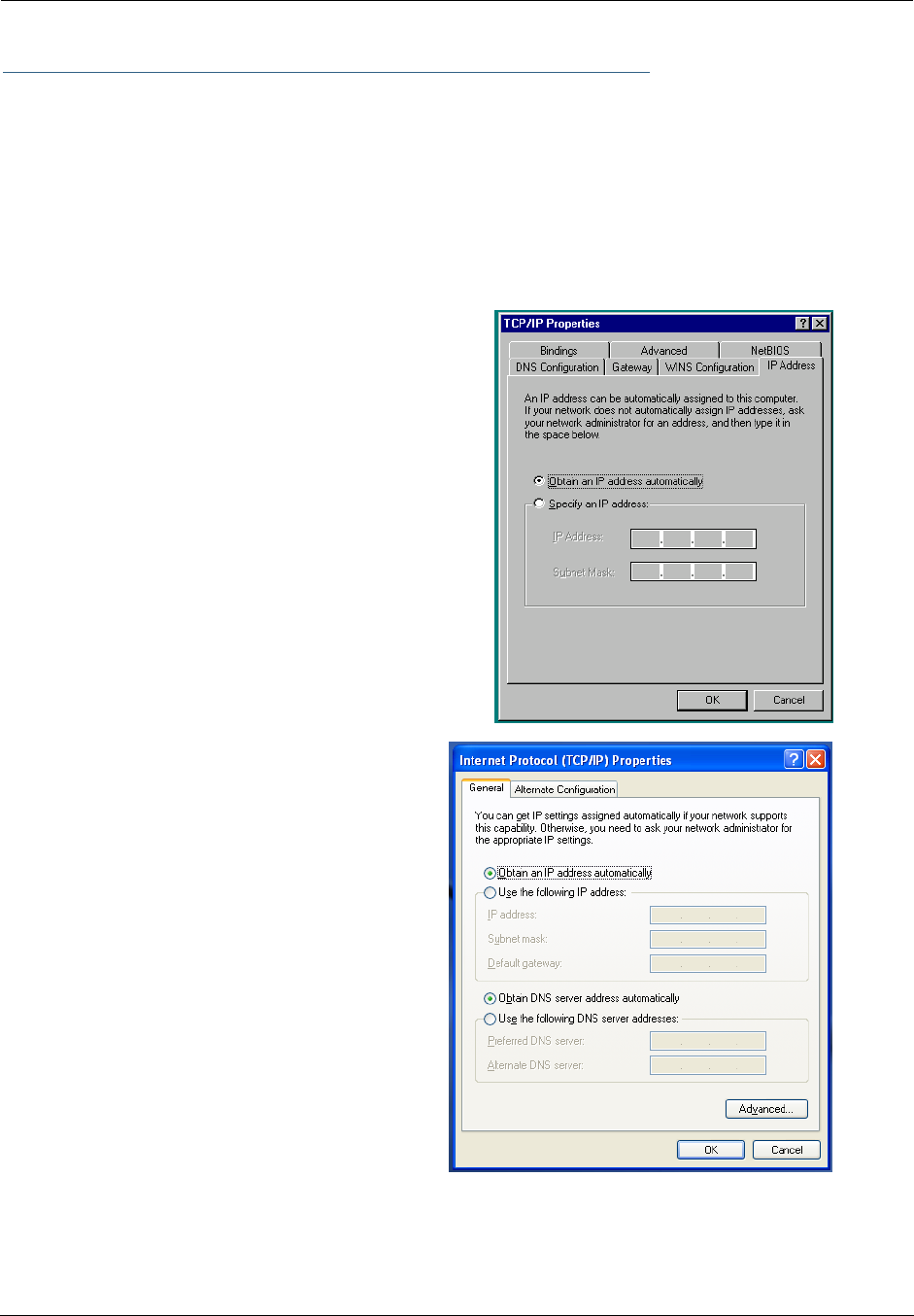
Microsoft Windows:
Step 1. Navigate to the TCP/IP Properties Control Panel.
a. Some Windows
versions follow a
path like this:
Start menu -> Settings ->
Control Panel -> Network
(or Network and Dial-up
Connections -> Local Area
Connection -> Properties) -
> TCP/IP
[your_network_card] or
Internet Protocol [TCP/IP]
-> Properties
b. Some Windows
versions follow a
path like this:
Start menu -> Con-
trol Panel -> Net-
work and Internet
Connections -> Net-
work Connections ->
Local Area Connec-
tion -> Properties ->
Internet Protocol
[TCP/IP] -> Proper-
ties
23
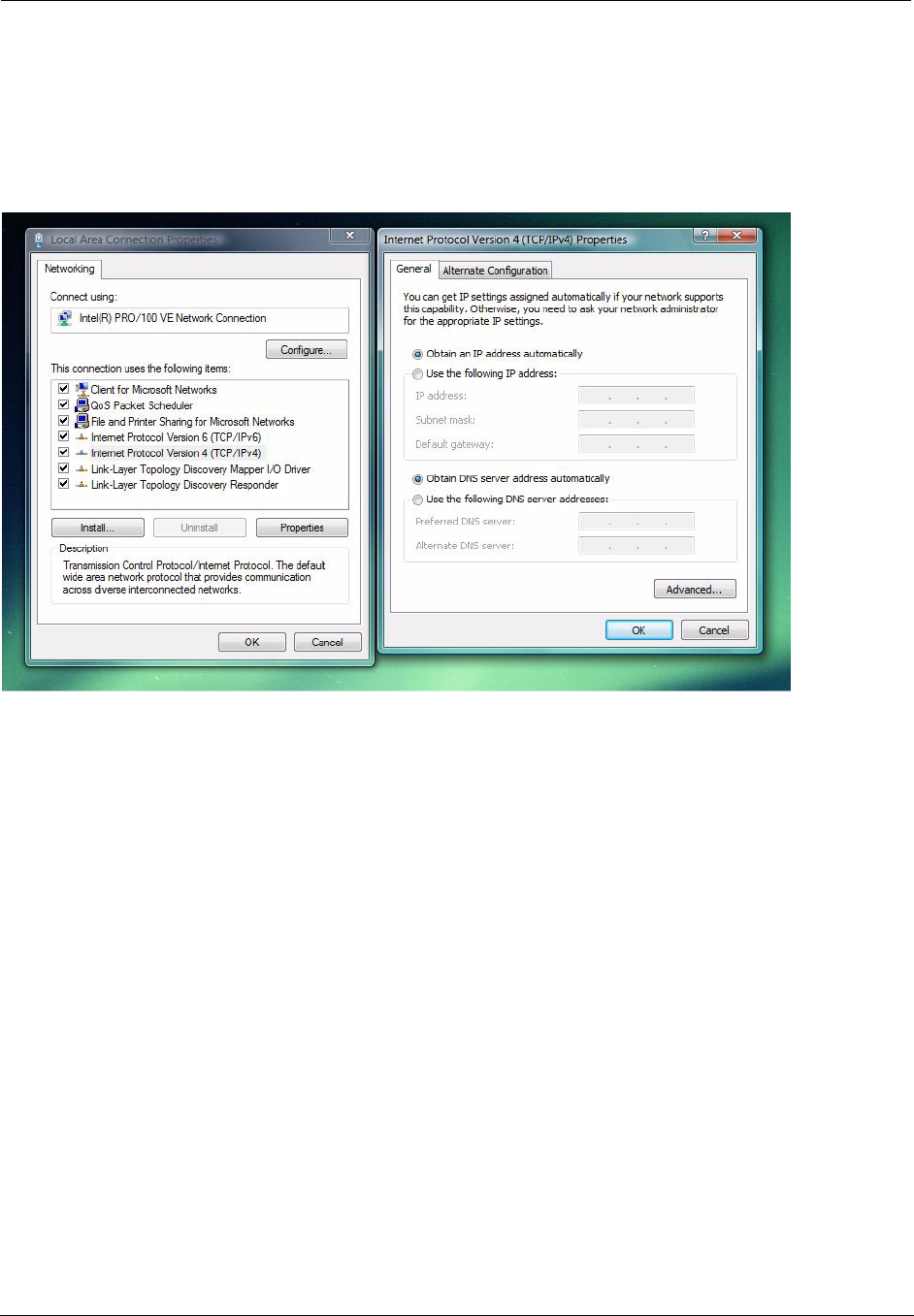
c. Windows Vista is set to obtain an IP address automatically by default. You may not need to configure it at
all.
To check, open the Networking Control Panel and select Internet Protocol Version 4 (TCP/IPv4). Click
the Properties button.
The Internet Protocol Version 4 (TCP/IPv4) Properties window should appear as shown.
If not, select the radio buttons shown above, and click the OK button.
Administrator’s Handbook
24
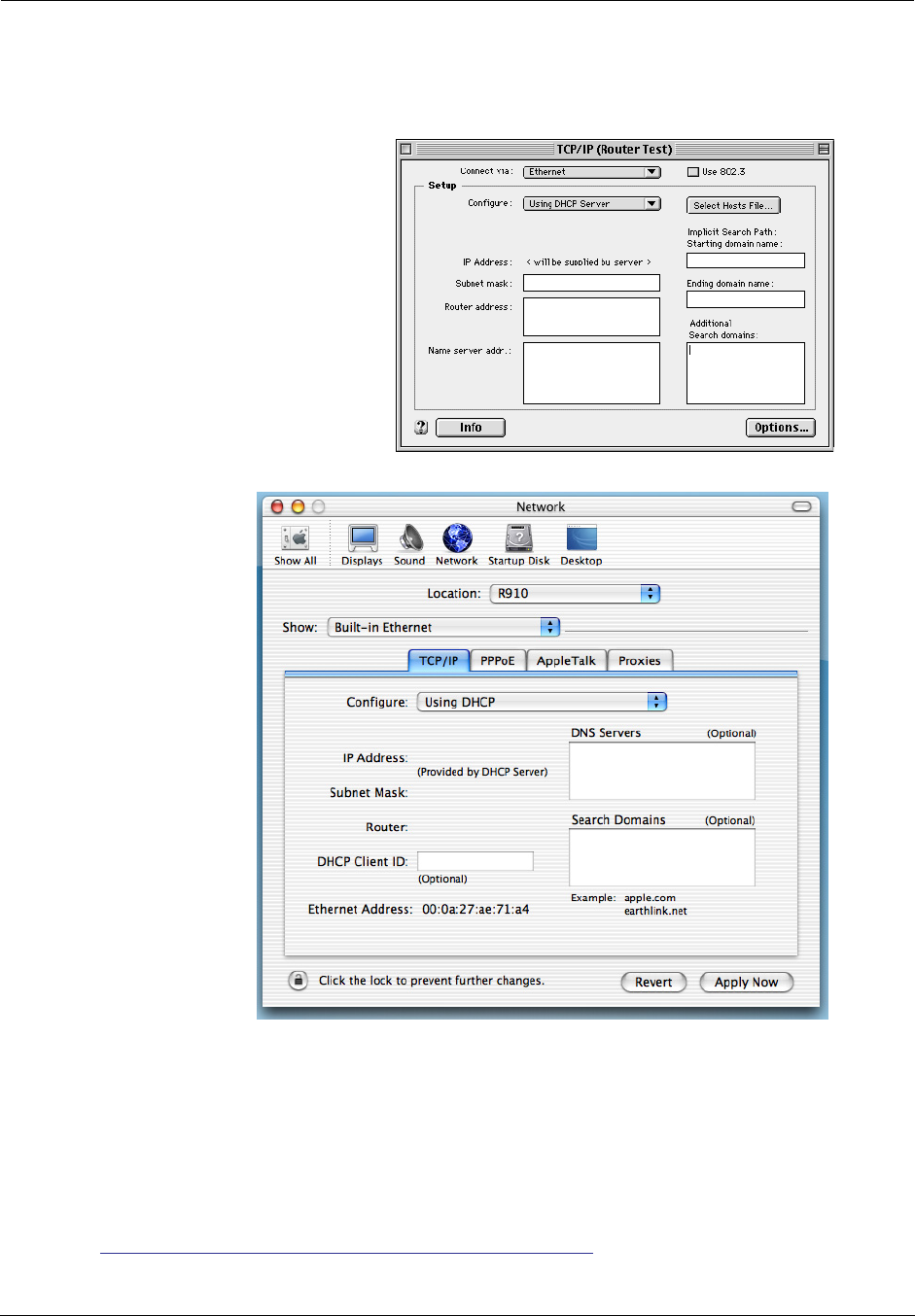
Macintosh MacOS 8 or higher or Mac OS X:
Step 1. Access the TCP/IP or Network control panel.
Then go to Step 2.
Step 2. Select Built-in Ethernet
Step 3. Select Configure Using DHCP
Step 4. Close and Save, if prompted.
Proceed to “Configuring the Motorola Netopia® Gateway” on page 25.
a. MacOS follows a
path like this:
Apple Menu ->
Control Pan-
els -> TCP/IP
Control Panel
b. Mac OS X follows
a path like this:
Apple Menu -> System Preferences -> Network
25
Configuring the Motorola Netopia® Gateway
1. Run your Web browser application, such as Firefox or Microsoft Internet Explorer, from
the computer connected to the Motorola Netopia® Gateway.
Enter http://192.168.1.254 in the Location text box.
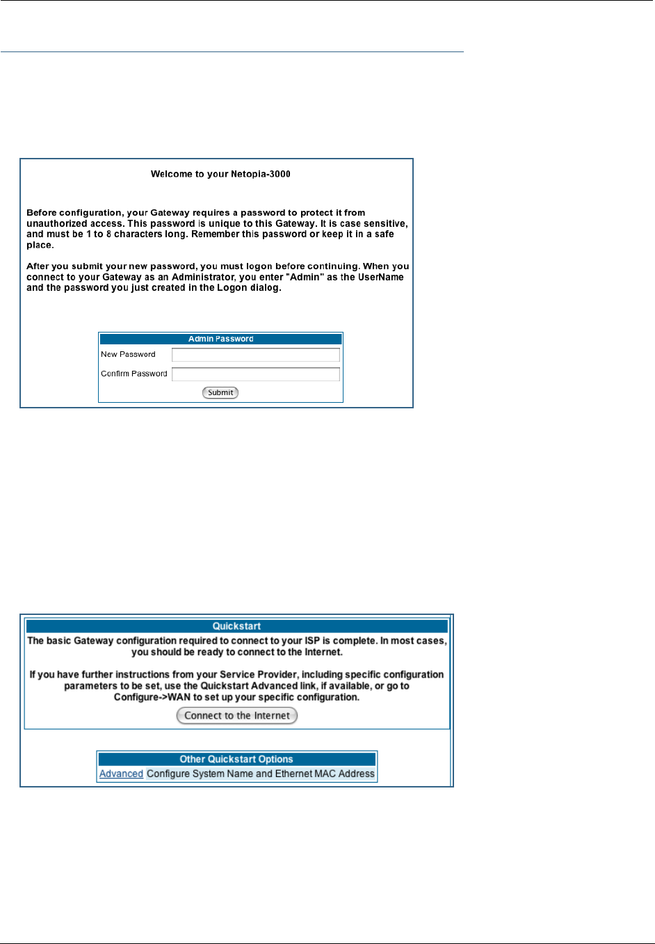
The Admin Password page appears.
Access to your Motorola Netopia® device can be controlled through two access control accounts,
Admin or User.
•The Admin, or administrative user, performs all configuration, management or maintenance operations
on the Gateway.
•The User account provides monitor capability only.
A user may NOT change the configuration, perform upgrades or invoke maintenance functions.
For the security of your connection, an Admin password must be set on the Motorola Netopia® unit.
MiAVo VDSL and Ethernet WAN models Quickstart
The browser then displays the Quickstart page.
2. Click the
Connect to the Internet
button.

Administrator’s Handbook
26
Once a connection is established, your browser is redirected to your service provider’s home page or a
registration page on the Internet.
☛ NOTE:
For MiAVo Series (3397GP) models, skip the rest of this section.
Congratulations! Your configuration is complete.
You can skip to “Home Page - Basic Mode” on page 31.
27
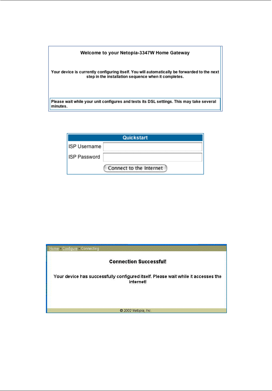
PPPoE Quickstart
For a PPPoE connection, your browser will display a different series of web pages:
The browser then displays the Quickstart web page.
3. Enter the username and password supplied by your Internet Service Provider. Click the
Connect to the Internet
button.
Once you enter your username and password here, you will no longer need to enter them whenever you
access the Internet. The Motorola Netopia® Gateway stores this information and automatically connects
you to the Internet.
The Gateway displays a message while it configures itself.
4. When the connection succeeds, your browser will display a success message.
Once a connection is established, your browser is redirected to your service provider’s home page or a
registration page on the Internet.
5. Congratulations! Your installation is complete. You can now surf to your favorite Web
sites by typing an URL in your browser’s location box or by selecting one of your favor-
ite Internet bookmarks.
Administrator’s Handbook
28
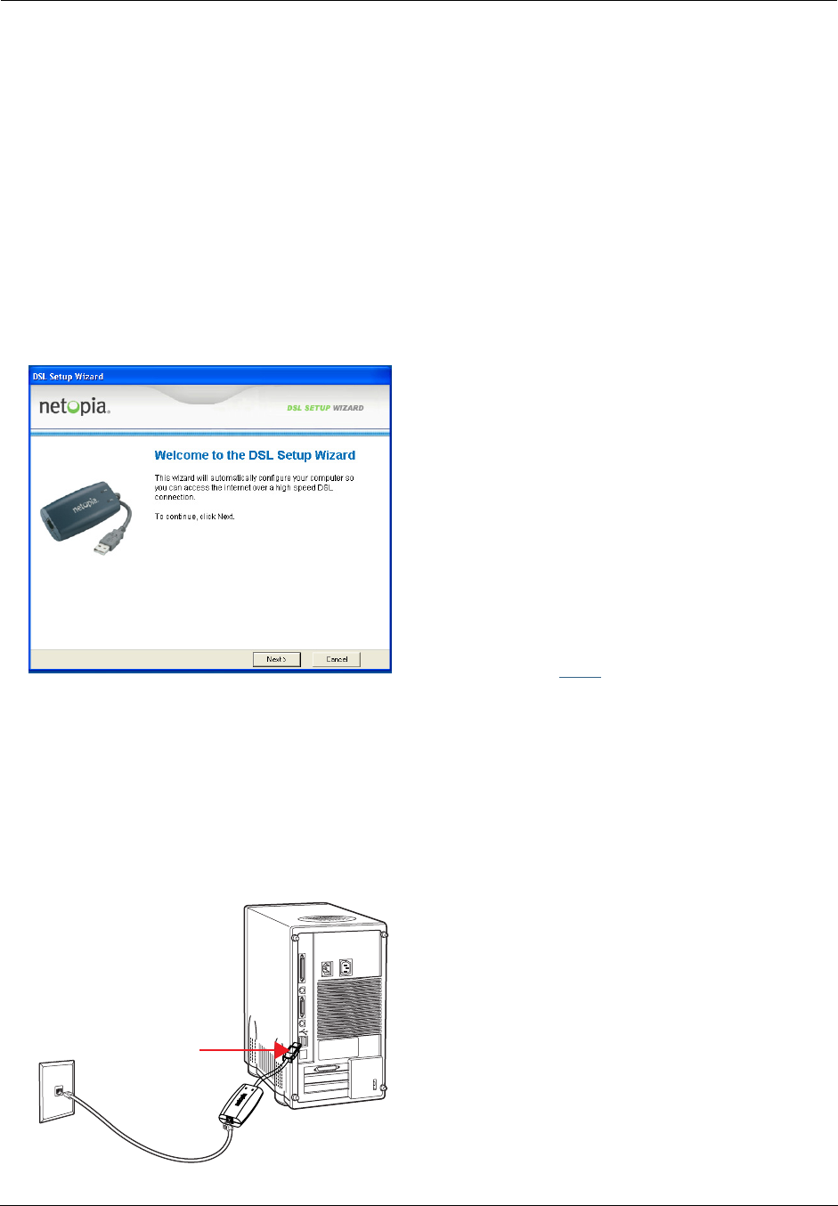
Set up the Motorola Netopia® Pocket Gateway
Your Motorola Netopia® 3342N/3352N Pocket Gateway comes with its own installation wizard.
•If you are using Windows 98, insert the CD.
•If you are using Windows XP, Windows 2000, Windows NT or Windows Vista, you don’t even need the
CD.
Follow these easy setup steps:
1. Plug the Motorola Netopia® Pocket Gateway into a USB port on your PC.
2. Whether you use the CD (Windows 98) or not (all other Windows versions), on Windows-based
PCs, the Motorola Netopia® Installation Wizard will launch automatically.
The Motorola Netopia® Installation Wizard will assist you to configure your PC to work with the Motorola
Netopia® pocket Gateway. Follow the on-screen instructions.
To proceed, click the
Next
button.
The Motorola Netopia® Installation Wizard performs a series of checks on your system and then will
install USB drivers for your connection.
3. Place the Motorola Netopia® Pocket Gateway near your PC so you can see it easily.
Make sure any cables are kept away from power cords, fluorescent lighting fixtures, and other sources
of electrical interference.
4. When the wizard prompts you, connect the RJ-11 Telephone Cable from the DSL port on the
Motorola Netopia® Pocket Gateway to the ADSL phone jack.
The DSL indicator light should blink for up to two minutes and then come on solid green once the device
is connected to your computer.
phone jack
Netopia Pocket Gateway/
RJ-11 phone cable
USB port

29
The Wizard displays a success message when the settings are configured.
5. The Motorola Netopia® Installation Wizard will then launch your web browser and display the
Welcome
page where you configure your Motorola Netopia® Pocket Gateway.

Administrator’s Handbook
30
Motorola Netopia® Gateway Status Indicator Lights
Colored LEDs on your Motorola Netopia® Gateway indicate the status of various port activity. Different
Gateway models have different ports for your connections and different indicator LEDs. The Quickstart
Guide accompanying your Motorola Netopia® Gateway describes the behavior of the various indicator LEDs.
Example status indicator lights
netopia
Status Indicator Lights (LEDs)
31
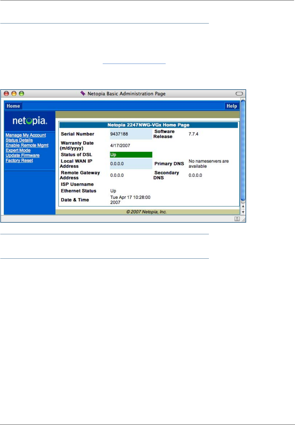
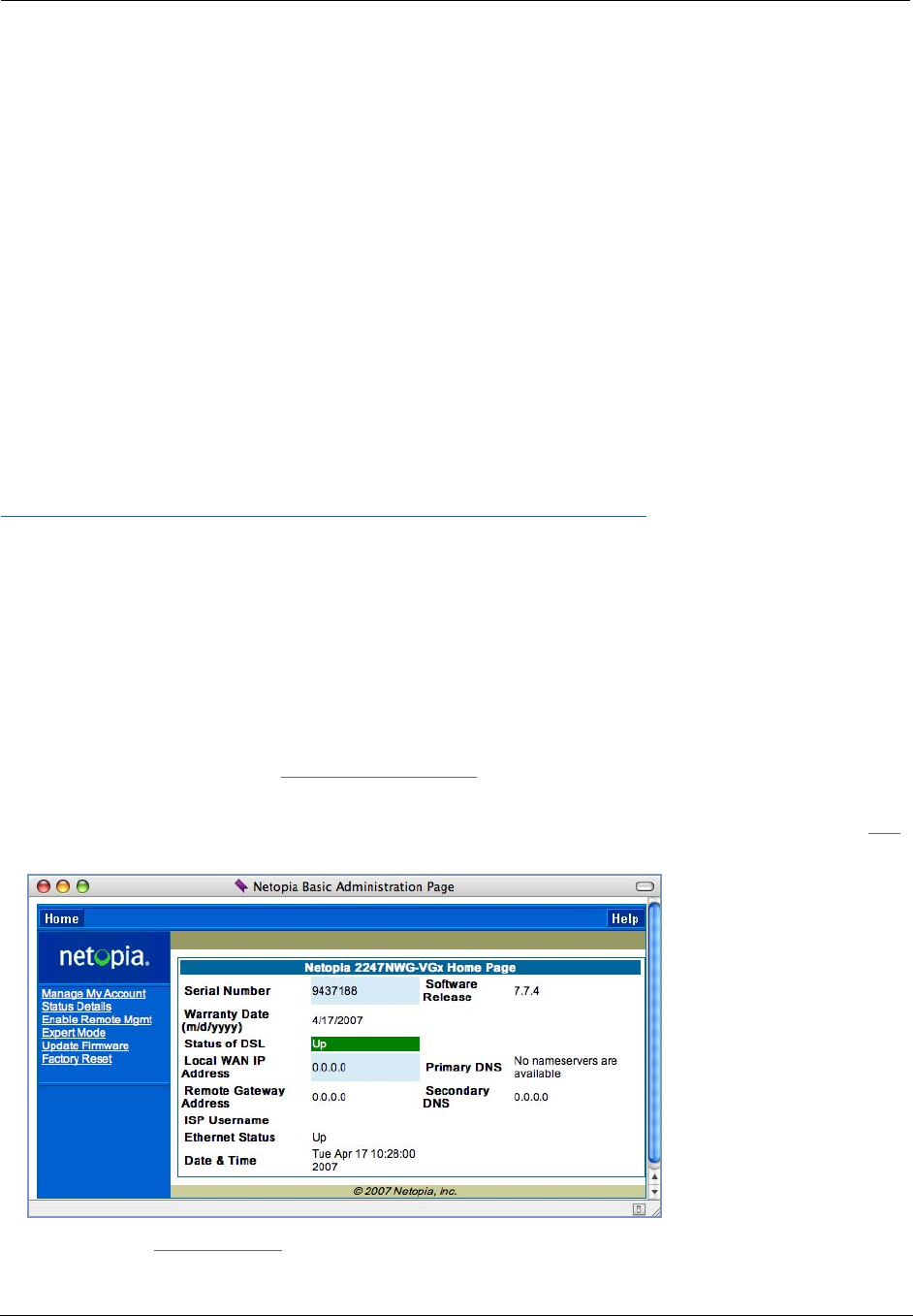
Home Page - Basic Mode
After you have performed the basic Quickstart configuration, any time you log in to your Motorola Netopia®
Gateway you will access the Motorola Netopia® Gateway Home Page.
You access the Home Page by typing
http://192.168.1.254
in your Web browser’s location box.
The Basic Mode Home Page appears.
☛ VoIP-enabled Gateways also display VoIP phone information, as well.

Administrator’s Handbook
32
The Home Page displays the following information in the center section:
The links in the left-hand column on this page allow you to manage or configure several features of your
Gateway. Each link is described in its own section.
Item Description
Serial Number This is the unique serial number of your Gateway.
Software
Release
This is the version number of the current embedded software in your Gate-
way.
Warranty Date This is the date that your Gateway was installed and enabled.
Status of DSL DSL connection (Internet) is either Up or Down
Status of
Connection
‘Waiting for DSL’ is displayed while the Gateway is training. This should
change to ‘Up’ within two minutes.
‘Up’ is displayed when the ADSL line is synched and the PPPoE session is
established.
‘Down’ indicates inability to establish a connection; possible line failure.
Local WAN IP
Address
This is the negotiated address of the Gateway’s WAN interface. This
address is usually dynamically assigned.
Remote
Gateway
Address
This is the negotiated address of the remote router to which this Gateway
is connected.
Primary DNS
Secondary DNS
These are the negotiated DNS addresses.
ISP Username This is your PPPoE username as assigned by your service provider.
Ethernet Status (if so equipped) Local Area Network (Ethernet) is either Up or Down
USB Status If your Gateway is so equipped, Local Area Network (USB) is either Up or
Down
Line 1/2
Registration
If your Gateway is so equipped, voice Line 1 and/or 2 is either Idle or Con-
nected
Date & Time This is the current UTC time; blank if this is not available due to lack of a
network connection.
33
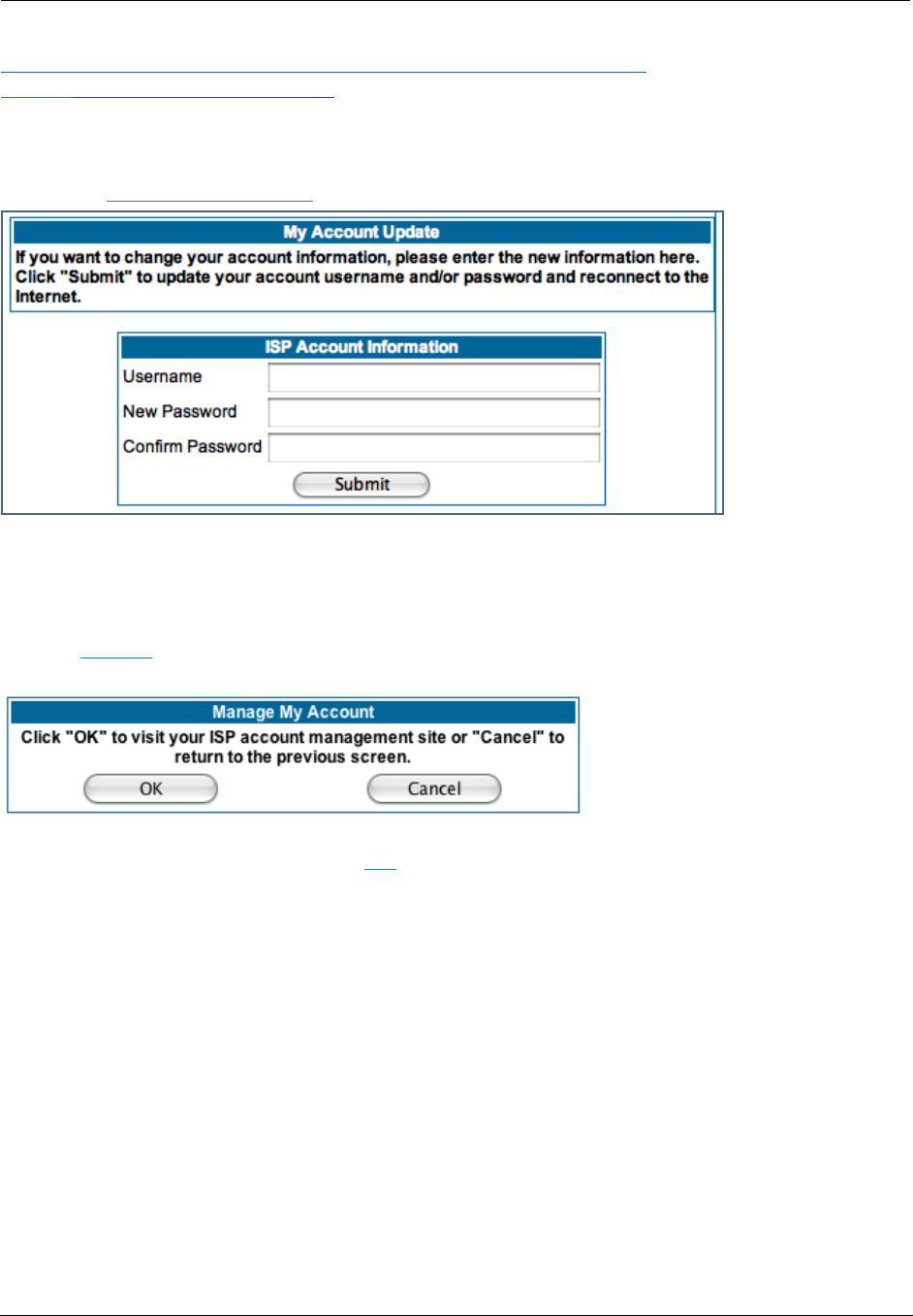
Link: Manage My Account
You can change your ISP account information for the Motorola Netopia® Gateway. You can also manage
other aspects of your account on your service provider’s account management Web site.
Click on the
Manage My Account
link. The Manage My Account page appears.
If you have a PPPoE account, enter your username, and then your new password. Confirm your new pass-
word. For security, your actual passwords are not displayed on the screen as you type. You must enter the
new password twice to be sure you have typed it correctly.
Click the
Submit
button.
If you have a non-PPPoE account, click the
OK
button.
You will be taken to your service provider’s Web site account management page.
Administrator’s Handbook
34
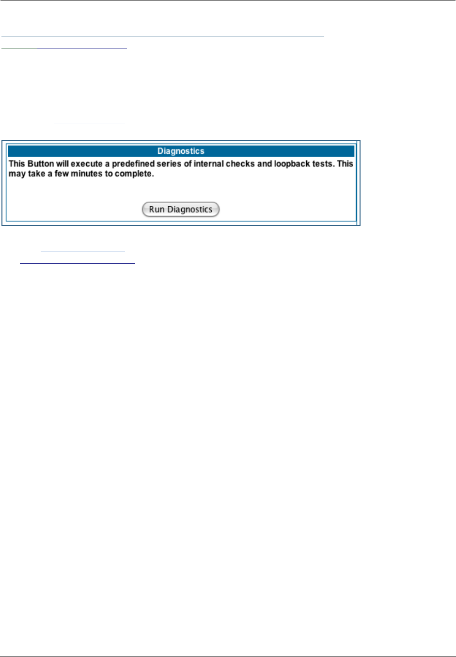
Link: Status Details
If you need to diagnose any problems with your Motorola Netopia® Gateway or its connection to the Inter-
net, you can run a sophisticated diagnostic tool. It checks several aspects of your physical and electronic
connection and reports its results on-screen. This can be useful for troubleshooting, or when speaking with
a technical support technician.
Click on the
Status Details
link. The Diagnostics page appears.
Click the
Run Diagnostics
button to run your diagnostic tests. For a detailed description of these tests,
see “Diagnostics” on page 217.
35
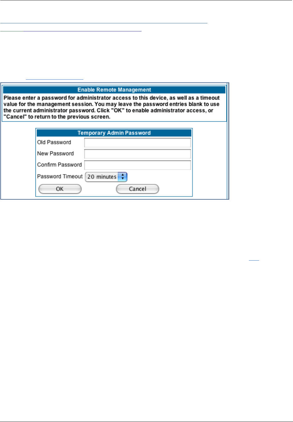
Link: Enable Remote Management
This link allows you to authorize a remotely-located person, such as a support technician, to directly access
your Motorola Netopia® Gateway. This is useful for fixing configuration problems when you need expert
help. You can limit the amount of time such a person will have access to your Gateway. This will prevent
unauthorized individuals from gaining access after the time limit has expired.
Click the
Enable Rmt Mgmt
link. The Enable Remote Management page appears.
Since you’ve already has entered an Admin password, you can use that Admin password or enter a new
password. If you enter a new password, it becomes the temporary Admin password. After the time-out
period has expired, the Admin password reverts to the original Admin password you entered.
Enter a temporary password for the person you want to authorize, and confirm it by typing it again. You can
select a time-out period for this password, from 5 to 30 minutes, from the pull-down menu. Be sure to tell
the authorized person what the password is, and for how long the time-out is set. Click the
OK
button.
Administrator’s Handbook
36
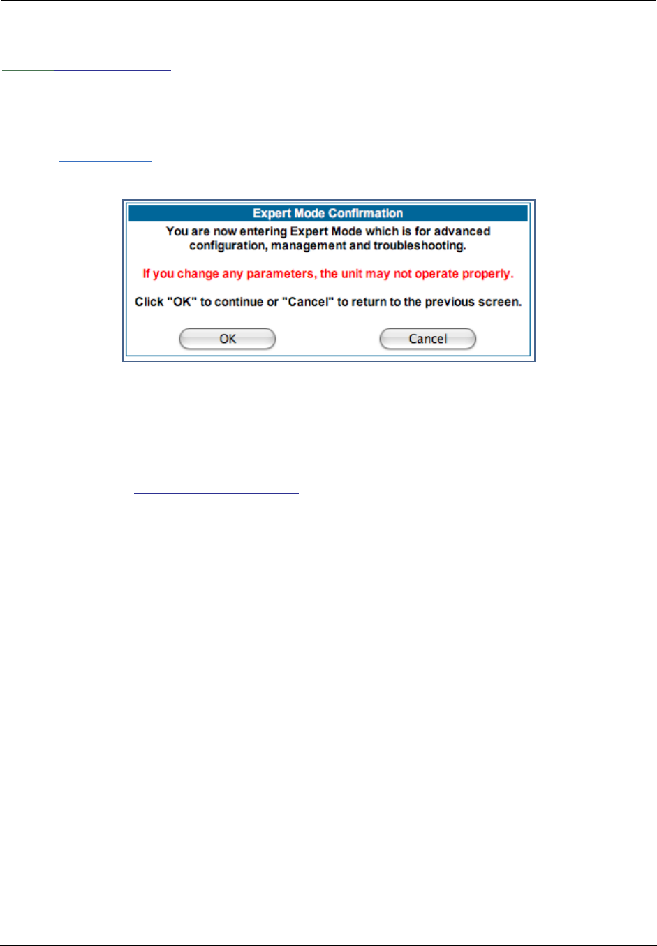
Link: Expert Mode
Most users will find that the basic Quickstart configuration is all that they ever need to use. Some users,
however, may want to do more advanced configuration. The Motorola Netopia® Gateway has many
advanced features that can be accessed and configured through the Expert Mode pages.
Click the
Expert Mode
link to display the Expert Mode Confirmation page.
You should carefully consider any configuration changes you want to make, and be sure that your service
provider supports them.
Once you click the OK button you will be taken to the Expert Mode Home Page.
The Expert Mode Home Page is the main access point for configuring and managing the advanced features
of your Gateway. See “Expert Mode” on page 39 for information.
37
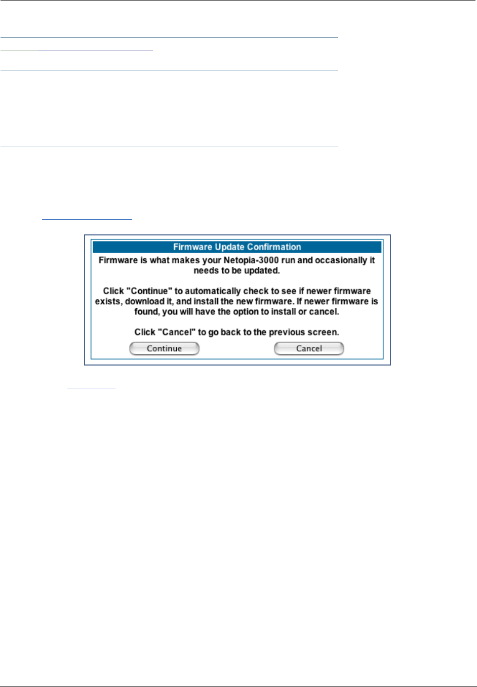
Link: Update Firmware
☛ NOTE:
(This link is not available on the 3342/3352 models, since firmware updates must be
upgraded via the USB host driver.
3342N/3352N models do support this feature.)
Periodically, the embedded firmware in your Gateway may be updated to improve the operation or add new
features. Your gateway includes its own onboard installation capability. Your service provider may inform
you when new firmware is available, or you can check for yourself.
Click the
Update Firmware
link. The Firmware Update Confirmation page appears.
If you click the
Continue
button, the Gateway will check a remote Firmware Server for the latest firmware
revision. If a newer version is found, your firmware will be automatically updated once you confirm the
installation.
Administrator’s Handbook
38
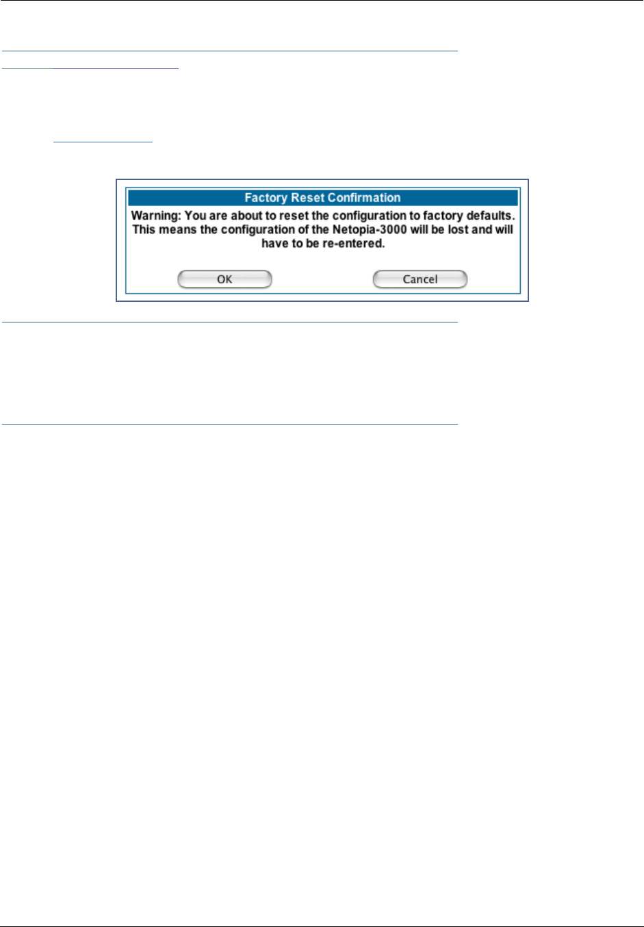
Link: Factory Reset
In some cases, you may need to clear all the configuration settings and start over again to program the
Motorola Netopia® Gateway. You can perform a factory reset to do this.
Click on
Factory Reset
to reset the Gateway back to its original factory default settings.
☛ NOTE:
Exercise caution before performing a Factory Reset. This will erase any configuration changes
that you may have made and allow you to reprogram your Gateway.
39
CHAPTER 3 Expert Mode
Using the Expert Mode Web-based user interface for the Motorola Netopia® 2200-, 3300- and 7000-series
Gateway you can configure, troubleshoot, and monitor the status of your Gateway.
Accessing the Expert Web Interface
Open the Web Connection
Once your Gateway is powered up, you can use any recent version of the best-known web browsers such as
Netscape Navigator or Microsoft Internet Explorer from any LAN-attached PC or workstation. The procedure
is:
1. Enter the name or IP address of your Motorola Netopia® Gateway in the Web browser's
window and press Return.
For example, you would enter http://192.168.1.254.
2. If an administrator or user password has been assigned to the Motorola Netopia® Gate-
way, enter
Admin
or
User
as the username and the appropriate password and click OK.
The Basic Mode Home Page opens.
3. Click on the Expert Mode link in the left-hand column of links.

Administrator’s Handbook
40
You are challenged to confirm your choice.
Click OK.
The Home Page opens in Expert Mode.
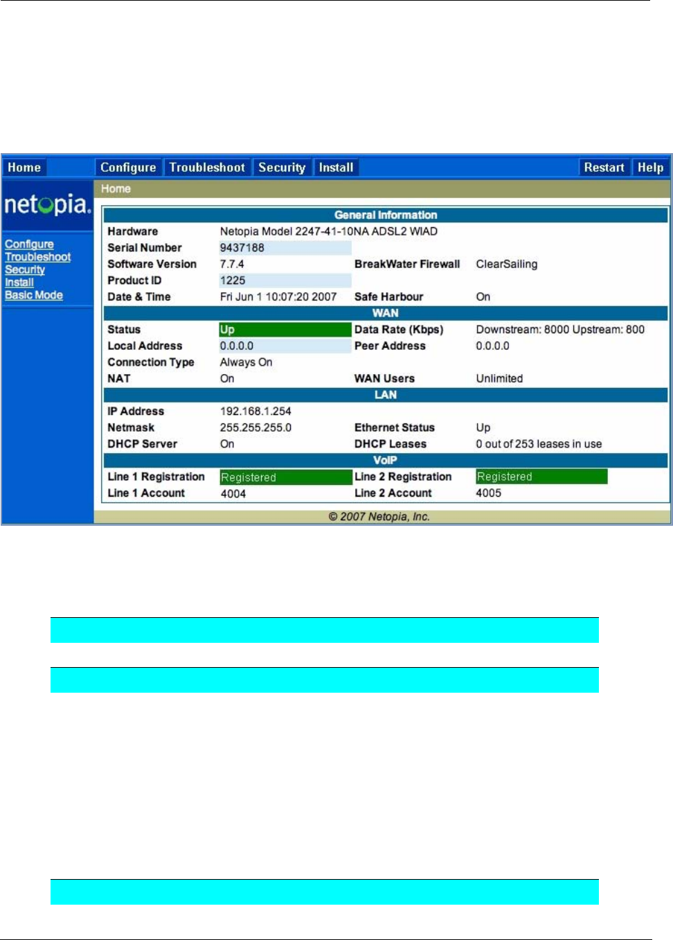
41
Home Page - Expert Mode
The Home Page is the summary page for your Motorola Netopia® Gateway. The toolbar at the top provides
links to controlling, configuring, and monitoring pages. Critical configuration and operational status is dis-
played in the center section.
Home Page - Information
The Home page’s center section contains a summary of the Gateway’s configuration settings and opera-
tional status.
Summary Information
Field Status and/or Description
General Information
Hardware Model number and summary specification
Serial Number Unique serial number, located on label attached to bottom of unit
Software Version Release and build number of running Motorola Netopia® Operating System.
Product ID Refers to internal circuit board series; useful in determining which software
upgrade applies to your hardware type.
Date & Time This is the current UTC time; blank if this is not available due to lack of a
network connection.
Breakwater Firewall If the optional feature key is installed: Status of the Breakwater Firewall:
ClearSailing, SilentRunning, or LANdLocked.
Safe Harbour If the optional feature key is installed: SafeHarbour VPN IPsec Tunnel option
(if installed): either On or Off.
WAN

Administrator’s Handbook
42
Status Wide Area Network may be Waiting for DSL (or other waiting status), Up or
Down
Data Rate (Kbps) Once connected, displays DSL speed rate, Downstream and Upstream
Local Address IP address assigned to the WAN port.
Peer Address The IP address of the gateway to which the connection defaults. If doing
DHCP, this info will be acquired. If doing PPP, this info will be negotiated.
Connection Type May be either Instant On or Always On.
NAT On or Off. ON if using Network Address Translation to share the IP address
across many LAN users.
WAN Users Displays the number of users allotted and the total number available for
use.
LAN
IP Address Internal IP address of the Motorola Netopia® Gateway.
Netmask Defines the IP subnet for the LAN
Default is 255.255.255.0 for a Class C device
DHCP Server On or Off. ON if using DHCP to get IP addresses for your LAN client
machines.
DHCP Leases A “lease” is held by each LAN client that has obtained an IP address through
DHCP.
Ethernet (or USB)
Status
Status of your Ethernet network connection (if supported). Up or Down.
VoIP
Line 1/2 Registration If your Gateway is so equipped, voice Line 1 and/or 2 is either Idle or Reg-
istered
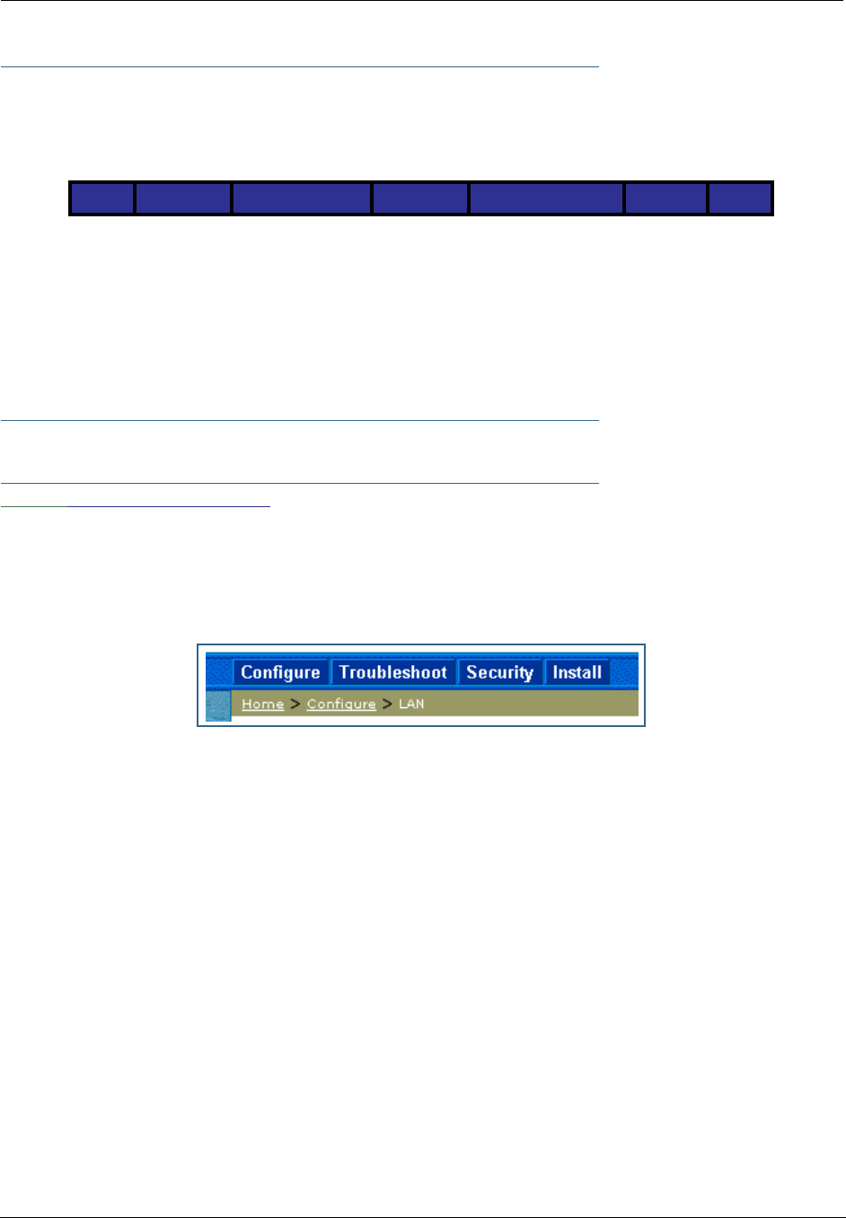
43
Toolbar
The toolbar is the dark blue bar at the top of the page containing the major navigation buttons. These but-
tons are available from almost every page, allowing you to move freely about the site.
Navigating the Web Interface
Link: Breadcrumb Trail
The breadcrumb trail is built in the light brown area beneath the toolbar. As you navigate down a path within
the site, the trail is built from left to right. To return anywhere along the path from which you came, click on
one of the links.
Home Configure Troubleshoot Security Install Restart Help
Quickstart System Status Passwords Install Certificate
LAN Network Tools Firewall Install Key
WAN Diagnostics IPSec Install Software
Advanced Stateful Inspection
Packet Filter
Security Log
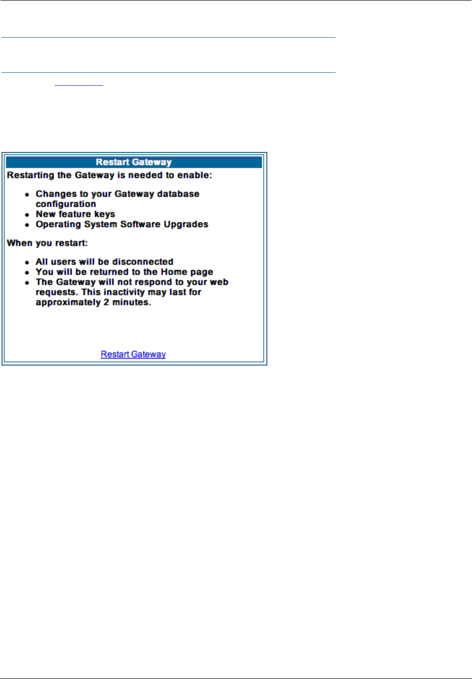
Administrator’s Handbook
44
Restart
Button: Restart
The Restart button on the toolbar allows you to restart the Gateway at any time. You will be prompted to
confirm the restart before any action is taken. The Restart Confirmation message explains the conse-
quences of and reasons for restarting the Gateway.
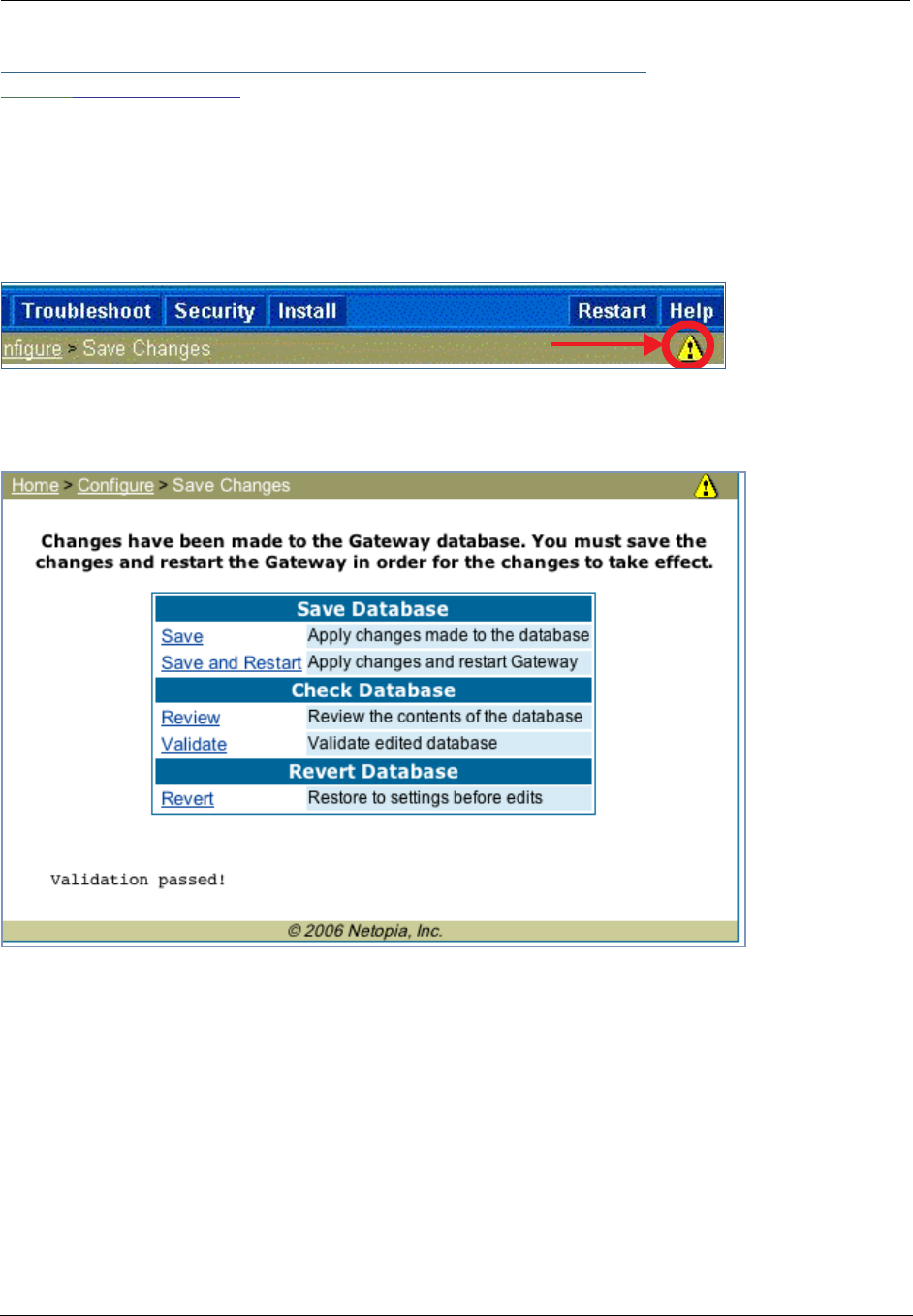
45
Link: Alert Symbol
The Alert symbol appears in the upper right corner if you make a database change; one in which a change
is made to the Gateway’s configuration. The Alert serves as a reminder that you must Save the changes
and Restart the Gateway before the change will take effect. You can make many changes on various
pages, and even leave the browser for up to 5 minutes, but if the Gateway is restarted before the changes
are applied, they will be lost. When you click on the Alert symbol, the Save Changes page appears. Here
you can select various options to save or discard these changes.
If more than one Alert is triggered, you will need to take action to clear the first Alert before you can see the
second Alert.
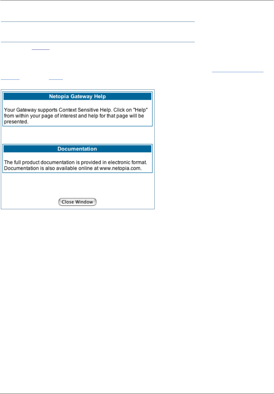
Administrator’s Handbook
46
Help
Button: Help
Context-sensitive Help is provided in your Gateway. The page shown here is displayed when you are on the
Home page or other transitional pages. To see a context help page example, go to Security -> Pass-
words, then click Help.
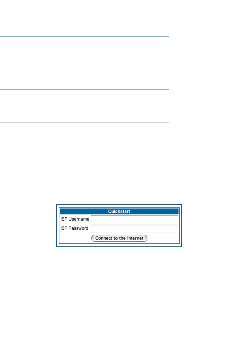
47
Configure
Button: Configure
The Configuration options are presented in the order of likelihood you will need to use them. Quickstart is
typically accessed during the hardware installation and initial configuration phase. Often, these settings
should be changed only in accordance with information from your Service Provider. LAN and WAN
settings are available to fine-tune your system. Advanced provides some special capabilities typically used
for gaming or small office environments, or where LAN-side servers are involved.
☛ This button will not be available if you log on as User.
Link: Quickstart
How to Use the Quickstart Page. Quickstart is normally used immediately after the new hardware
is installed. When you are first configuring your Gateway, Quickstart appears first.
(Once you have configured your Gateway, logging on displays the Home page. Thereafter, if you need to use
Quickstart, choose it from the Expert Mode Configure menu.)
Setup Your Gateway using a PPP Connection.
This example screen is the for a PPP Quickstart configuration. Your gateway authenticates with the Ser-
vice Provider equipment using the ISP Username and Password. These values are given to you by your Ser-
vice Provider.
1. Enter your ISP Username and ISP Password.
2. Click Connect to the Internet.

Administrator’s Handbook
48
A brief message is displayed while the Gateway attempts to establish a connection.
3. When the connection succeeds, your browser will display your Service Provider’s
home page.
If you encounter any problems connecting, refer to the chapters “Basic Troubleshooting” on page 193 or
“Advanced Troubleshooting” on page 207.
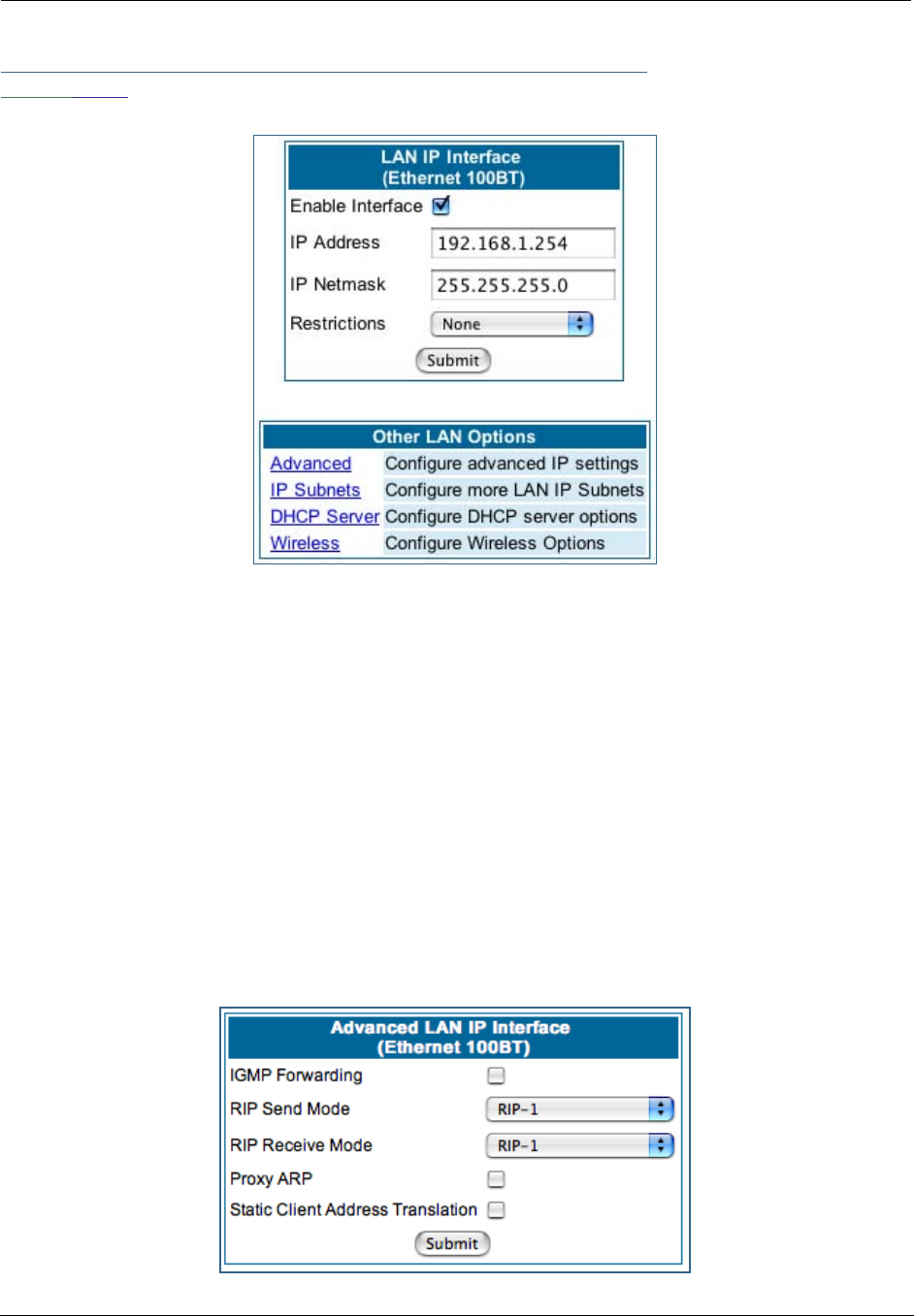
49
Link: LAN
* Enable Interface: Enables all LAN-connected computers to share resources and to connect to the WAN.
The Interface should always be enabled unless you are instructed to disable it by your Service Provider dur-
ing troubleshooting.
* IP Address: The LAN IP Address of the Gateway. The IP Address you assign to your LAN inter face must
not be used by another device on your LAN network.
* IP Netmask: Specifies the subnet mask for the TCP/IP network connected to the virtual circuit. The sub-
net mask specifies which bits of the 32-bit binary IP address represent network information. The default
subnet mask for most networks is 255.255.255.0 (Class C subnet mask.)
* Restrictions: Specifies whether an administrator can open a Web Administrator or Telnet connection to
the Gateway over the LAN interface in order to monitor and configure the Gateway. On the LAN Interface,
you can enable or disable administrator access. By default, administrative restrictions are turned off,
meaning an administrator can open a Web Administrator or Telnet connection through the LAN Interface.
• Advanced: Clicking on the Advanced link displays the Advanced LAN IP Interface page.
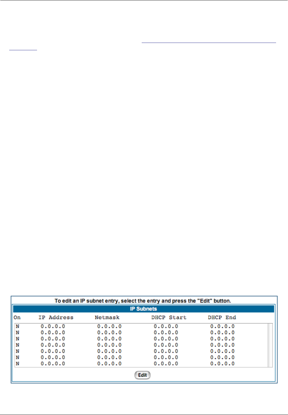
Administrator’s Handbook
50
•IGMP Forwarding: The default setting is Disabled. If you check this option, it will enable Internet Group
Management Protocol (IGMP) multicast forwarding. IGMP allows a router to determine which host groups
have members on a given network segment. See “IGMP (Internet Group Management Protocol)” on
page 100 for more information.
•RIP Send Mode: Specifies whether the gateway should use Routing Information Protocol (RIP) broad-
casts to advertise its routing tables to other routers on your network. You may choose from the following
protocols:
• RIP-1: Routing Information Protocol version 1
• RIP-2: RIP Version 2 is an extension of the original Routing Information Protocol (RIP-1) that expands
the amount of useful information in the RIP packets. While RIP-1 and RIP-2 share the same basic algo-
rithms, RIP-2 supports several new features, including inclusion of subnet masks in RIP packets and
implementation of multicasting instead of broadcasting (which reduces the load on hosts which do not
support routing protocols.
• RIP-1 compatibility: Compatible with RIP version 1
• RIP-2 with MD5: MD5 authentication is an extension of RIP-2 that increases security by requiring an
authentication key when routes are advertised.
• RIP MD5 Key: Secret password when using RIP-2 with MD5.
•RIP Receive Mode: Specifies whether the Gateway should use Routing Information Protocol (RIP)
broadcasts to update its routing tables with information received from other routers on your network.
The protocol choices are the same as for the RIP send mode.
•Proxy ARP: Specifies whether you want the Gateway to respond when it receives an address resolution
protocol for devices behind it. This is a way to make a computer that is physically located on one net-
work appear to be part of a different physical network connected to the same Gateway. It allows you to
hide a computer with a public IP address on a private network behind your Gateway, and still have the
computer appear to be on the public network “in front of” the Gateway.
•Static Client Address Translation: If you check this checkbox, this feature allows a statically
addressed computer whose IP address falls outside of the LAN subnet(s) to simply plug in and get
online without any manual configuration on either the host or the Motorola Netopia® Gateway. If
enabled, statically addressed LAN hosts that have an address outside of LAN subnets will be able to
communicate via the Router’s WAN interface to the Internet. Supported static IP address values must
fall outside of the Router's LAN subnet(s).
• IP Subnets: The IP Subnets screen allows you to configure up to seven secondary subnets and their
DHCP ranges, by entering IP address/subnet mask pairs:
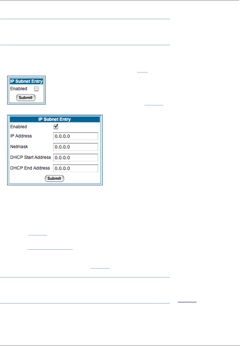
51
☛ Note:
You need not use this screen if you have only a single Ethernet IP subnet.
This screen displays seven rows of editable columns. All seven row labels are always visible, regardless of
the number of subnets configured.
•To add an IP subnet, select one of the rows, and click the Edit button.
Check the Enabled checkbox and click the Submit button.
The screen expands to allow you to enter subnet information.
If DHCP Server (see below) is not enabled, the DHCP Start Address and DHCP End Address fields do
not appear.
•Enter the Router’s IP address on the subnet in the IP Address field and the subnet mask for the subnet
in the Netmask field.
•Enter the DHCP Start Address and End Address of the subnet range in their respective fields.
Ranges cannot overlap and there may be only one range per subnet.
•Click the Submit button.
•When you are finished adding subnets, click the Alert icon at the upper right, and in the resulting page,
click the Save and Restart link.
To delete a configured subnet, set both the IP address and subnet mask values to 0.0.0.0, either explicitly
or by clearing each field and clicking the Submit button to commit the change.
☛ NOTE:
All additional DHCP ranges use the global lease period value. See page 52.
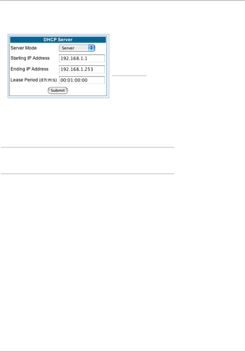
Administrator’s Handbook
52
• DHCP Server: Your Gateway can provide network configuration information to computers on your LAN,
using the Dynamic Host Configuration Protocol (DHCP).
If you already have a DHCP server on your LAN, you should
turn this service off.
If you want the Gateway to provide this service, click the
Server Mode pull-down menu, choose Server, then con-
figure the range of IP addresses that you would like the
Gateway to hand out to your computers.
You can also specify the length of time the computers can
use the configuration information; DHCP calls this period the lease time.
Your Service Provider may, for certain services, want to provide configuration from its DHCP servers to the
computers on your LANs. In this case, the Gateway will relay the DHCP requests from your computers to a
DHCP server in the Service Provider's network. Click the relay-agent and enter the IP address of the Service
Provider's DHCP server in the Server Address field. This address is furnished by the Service Provider.
☛ NOTE:
The Relay-agent option only works when NAT is off and the Gateway is in router mode.
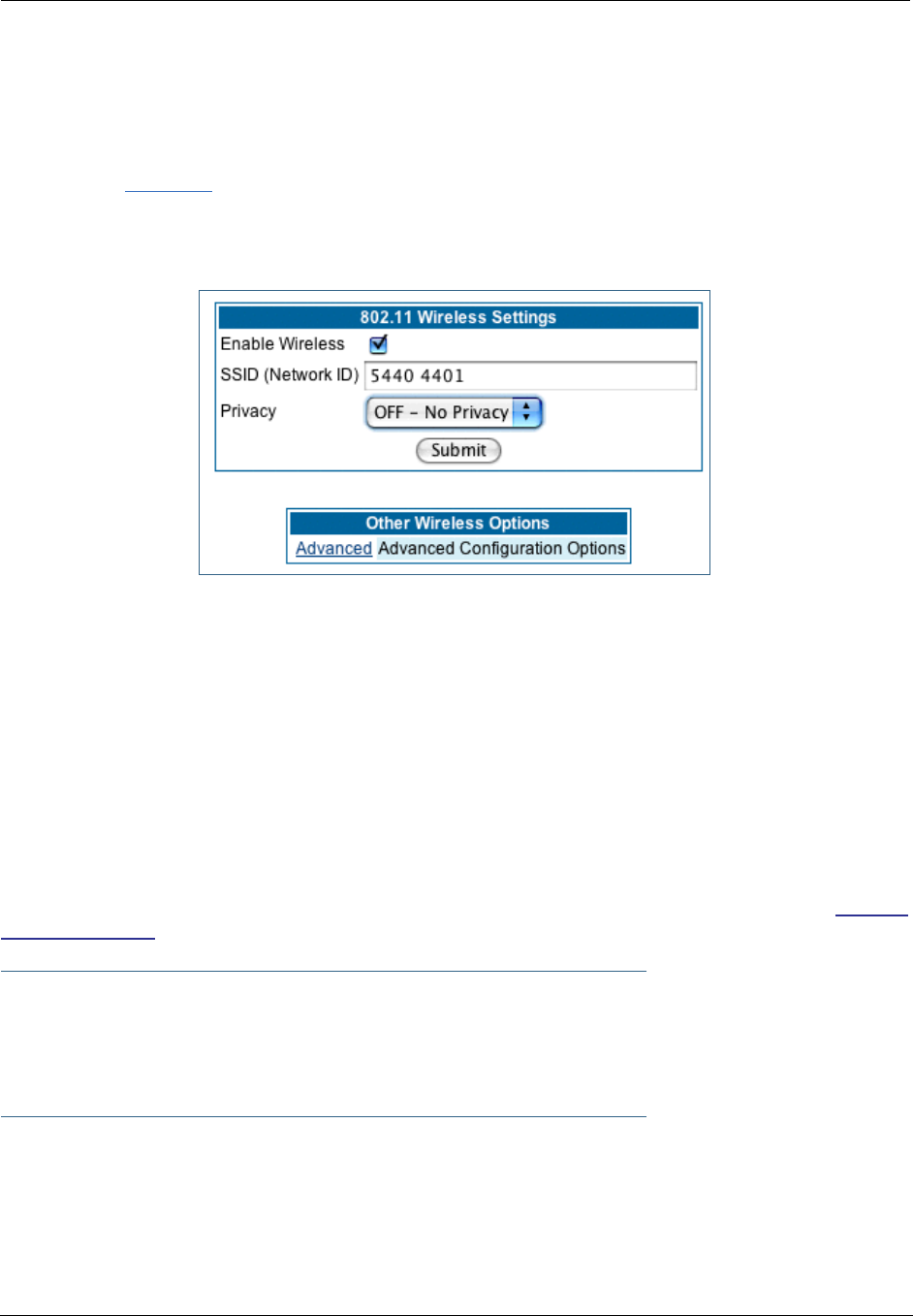
53
Wireless
(supported models)
If your Gateway is a wireless model (such as a 3347W) you can enable or disable the wireless LAN (WLAN)
by clicking the Wireless link.
Wireless functionality is enabled by default.
If you uncheck the Enable Wireless checkbox, the Wireless Options are disabled, and the Gateway will not
provide or broadcast any wireless LAN services.
SSID (Network ID): The SSID is preset to a number that is unique to your unit. You can either leave it as is,
or change it by entering a freeform name of up to 32 characters, for example “Ed’s Wireless LAN”. On client
PCs’ software, this might also be called the Network Name. The SSID is used to identify this particular wire-
less LAN. Depending on their operating system or client wireless card, users must either:
•select from a list of available wireless LANs that appear in a scanned list on their client
•or, if you are in Closed System Mode (see Enable Closed System Mode below), enter this name on
their clients in order to join this wireless LAN.
The pull-down menu for enabling Privacy offers four settings: WPA-802.1x, WPA-PSK, WEP - Automatic,
and Off - No Privacy. WEP-Manual is also available on the Advanced Configuration Options page. See “Pri-
vacy” on page 54.
☛ NOTE:
On the 2200-Series Gateways, WEP-Manual privacy is enabled by default. Use the Motorola
Netopia® Installation Wizard on the accompanying Motorola Netopia® CD to generate WEP
keys for connecting wireless client computers.
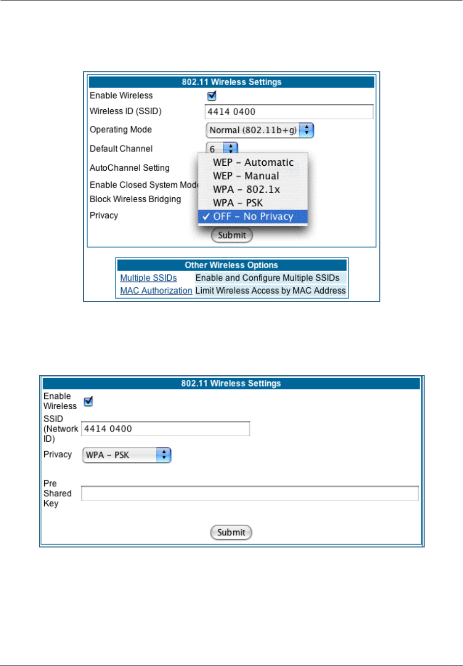
Administrator’s Handbook
54
Privacy
•Off - No Privacy provides no encryption on your wireless LAN data.
•WPA-802.1x provides RADIUS server authentication support.
•WPA-PSK provides Wireless Protected Access, the most secure option for your wireless network. This
mechanism provides the best data protection and access control.
The Pre Shared Key is a passphrase shared between the Router and the clients and is used to gener-
ate dynamically changing keys. The passphrase can be 8-63 characters or up to 64 hex characters. It is
recommended to use at least 20 characters for best security.
•WEP - Automatic is a passphrase generator. You enter a passphrase that you choose in the Pass-
phrase field. The passphrase can be any string of words or numbers.
You can provide a level of data security by enabling WEP (Wired Equivalent Privacy) for encryption of net-
work data. You can enable 40-, 128-, or 256-bit WEP Encryption (depending on the capability of your cli-
ent wireless card) for IP traffic on your LAN.
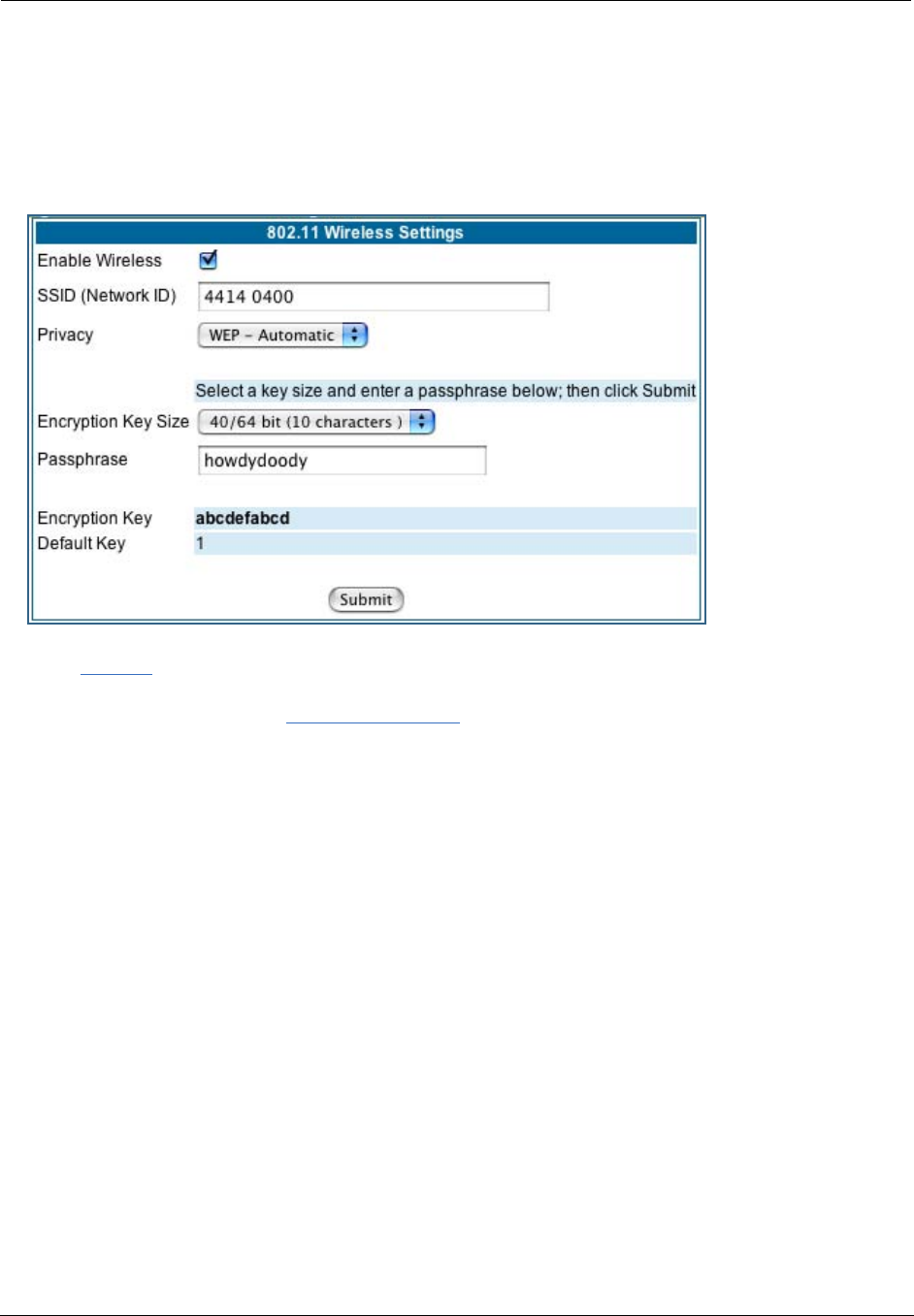
55
You select a single key for encryption of outbound traffic. The WEP-enabled client must have an identical
key of the same length, in the identical slot (1 – 4) as the Gateway, in order to successfully receive and
decrypt the traffic. Similarly, the client also has a ‘default’ key that it uses to encrypt its transmissions.
In order for the Gateway to receive the client’s data, it must likewise have the identical key of the same
length, in the same slot. For simplicity, a Gateway and its clients need only enter, share, and use the
first key.
Click the Submit button. The Alert icon appears.
Click the Alert icon, and then the Save and Restart link.
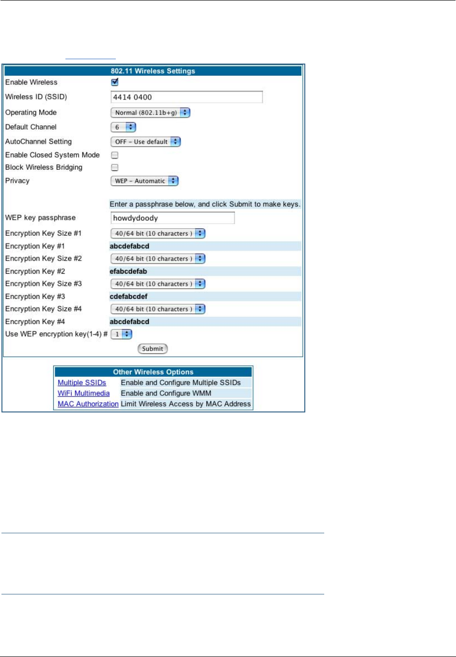
Administrator’s Handbook
56
Advanced
If you click the Advanced link, the advanced 802.11 Wireless Settings page appears.
Note: This page displays different options depending on which form of Privacy or other options you have
enabled.
You can then configure:
Operating Mode: The pull-down menu allows you to select and lock the Gateway into the wireless trans-
mission mode you want. For compatibility with clients using 802.11b (up to 11 Mbps transmission) and
802.11g (up to 20+ Mbps), select Normal (802.11b + g). To limit your wireless LAN to one mode or the
other, select 802.11b Only, or 802.11g Only.
☛ NOTE:
If you choose to limit the operating mode to 802.11b or 802.11g only, clients using the mode
you excluded will not be able to connect.
Default Channel: on which the network will broadcast. This is a frequency range within the 2.4Ghz band.
Channel selection depends on government regulated radio frequencies that vary from region to region. The
widest range available is from 1 to 14. However, in North America only 1 to 11 may be selected. Europe,

57
France, Spain and Japan will differ. Channel selection can have a significant impact on per formance,
depending on other wireless activity close to this Gateway. Channel selection is not necessary at the client
computers; the clients will scan the available channels seeking access points using the same SSID as the
client.
AutoChannel Setting: For 802.11G models, AutoChannel is a feature that allows the Motorola Netopia®
Gateway to determine the best channel to broadcast automatically.
Three settings are available from the pull-down menu: Off-Use default, At Startup, and Continuous.
•Off-Use default is the default setting; the Motorola Netopia® Gateway will use the configured default
channel selected from the previous pull-down menu.
•At Startup causes the Motorola Netopia® Gateway at startup to briefly initialize on the default channel,
then perform a full two- to three-second scan, and switch to the best channel it can find, remaining on
that channel until the next reboot.
•Continuous performs the at-startup scan, and will continuously monitor the current channel for any
other Access Point beacons. If an Access Point beacon is detected on the same channel, the Motorola
Netopia® Gateway will initiate a three- to four-minute scan of the channels, locate a better one, and
switch. Once it has switched, it will remain on this channel for at least 30 minutes before switching
again if another Access Point is detected.
Enable Closed System Mode: If enabled, Closed System Mode hides the wireless network from the scan-
ning features of wireless client computers. Unless both the wireless clients and the Router share the same
SSID in Closed System mode, the Router’s wireless LAN will not appear as an available network when
scanned for by wireless-enabled computers. Members of the Closed System WLAN must log onto the
Router’s wireless network with the identical SSID as that configured in the router.
Closed System mode is an ideal way to increase wireless security and to prevent casual detection by
unwanted neighbors, office users, or malicious users such as hackers.
If you do not enable Closed System Mode, it is more convenient, but potentially less secure, for clients to
access your WLAN by scanning available access points. You must decide based on your own network
requirements.
About Closed System Mode
Enabling Closed System Mode on your wireless Gateway provides another level of security, since your wire-
less LAN will no longer appear as an available access point to client PCs that are casually scanning for one.
Your own wireless network clients, however, must log into the wireless LAN by using the exact SSID of the
Motorola Netopia® Gateway.
In addition, if you have enabled WEP encryption on the Motorola Netopia® Gateway, your network clients
must also have WEP encryption enabled, and must have the same WEP encryption key as the Motorola
Netopia® Gateway.
Once the Motorola Netopia® Gateway is located by a client computer, by setting the client to a matching
SSID, the client can connect immediately if WEP is not enabled. If WEP is enabled then the client must also
have WEP enabled and a matching WEP key.
Wireless client cards from different manufacturers and different operating systems accomplish connecting
to a wireless LAN and enabling WEP in a variety of ways. Consult the documentation for your particular wire-
less card and/or operating system.
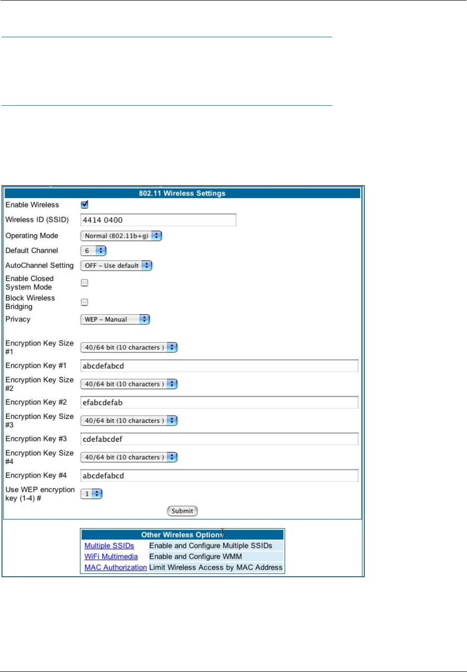
Administrator’s Handbook
58
☛ NOTE:
While clients may also have a passphrase feature, these are vendor-specific and may not nec-
essarily create the same keys. You can passphrase generate a set of keys on one, and manu-
ally enter them on the other to get around this.
Block Wireless Bridging: Check the checkbox to block wireless clients from communicating with other
wireless clients on the LAN side of the Gateway.
•WEP - Manual allows you to enter your own encryption keys manually. This is a difficult process, but
only needs to be done once. Avoid the temptation to enter all the same characters.
Encryption Key Size #1 – #4: Selects the length of each encryption key. The longer the key, the stronger
the encryption and the more difficult it is to break the encryption.
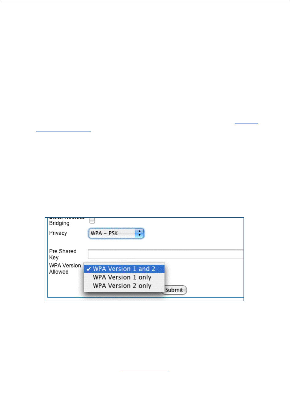
59
Encryption Key #1 – #4: The encryption keys. You enter keys using hexadecimal digits. For 40/64bit
encryption, you need ten digits; 26 digits for 128bit, and 58 digits for 256bit WEP. Hexadecimal characters
are 0 – 9, and a – f.
Examples:
•40bit: 02468ACE02
•128bit: 0123456789ABCDEF0123456789
•256bit: 592CA140F0A238B0C61AE162F592CA140F0A238B0C61AE162F21A09C
Use WEP encryption key (1 – 4) #: Specifies which key the Gateway will use to encrypt transmitted traffic.
The default is key #1.
You disable the wireless LAN by unchecking the Enable Wireless checkbox, clicking the Submit button, fol-
lowed by the Save and Restart link.
WPA Version Allowed
If you select either WPA-802.1x or WPA-PSK as your privacy setting, the WPA Version Allowed pull-down
menu appears to allow you to select the WPA version(s) that will be required for client connections. Choices
are:
•WPA Version 1 and 2, for maximum interoperability,
•WPA Version 1 Only, for backward compatibility,
•WPA Version 2 Only, for maximum security.
All clients must support the version(s) selected in order to successfully connect.
Multiple SSIDs
The Multiple Wireless SSIDs feature allows you to add additional network identifiers (SSIDs or Network
Names) for your wireless network.
To enable Multiple Wireless SSIDs, click the Multiple SSIDs link.
When the Multiple Wireless SSIDs screen appears, check the Enable SSID checkbox for each SSID you
want to enable.

Administrator’s Handbook
60
The screen expands to allow you to name each additional Wireless ID, and specify a Privacy mode for each
one.
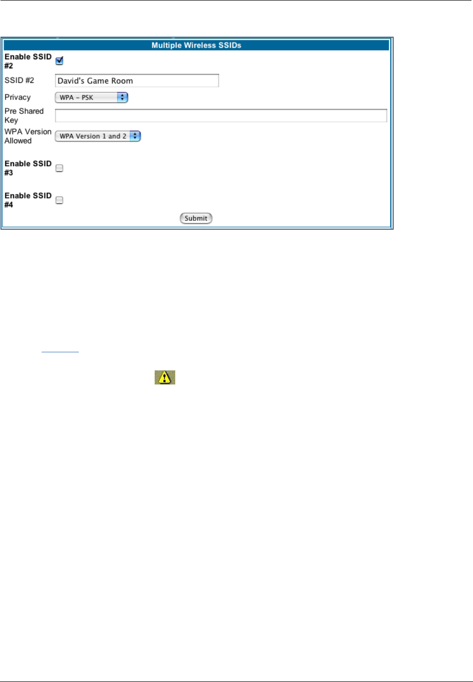
61
Privacy modes available from the pull-down menu for the multiple SSIDs are: WPA-PSK, WPA-802.1x, or
Off-No Privacy. WEP can also be selected on the additional SSIDs as long as it is not used on the primary
SSID. WEP can only be used on one SSID, so any others will not have WEP available.
These additional Wireless IDs are “Closed System Mode” Wireless IDs that will not be shown by a client
scan, and therefore must be manually configured at the client. In addition, wireless bridging between clients
is disabled for all members of these additional network IDs.
Click the Submit button.
After your first entry, the Alert icon will appear in the upper right corner of your screen. When you are
finished adding SSIDs, click the Alert icon, and Save your changes and restart the Gateway.
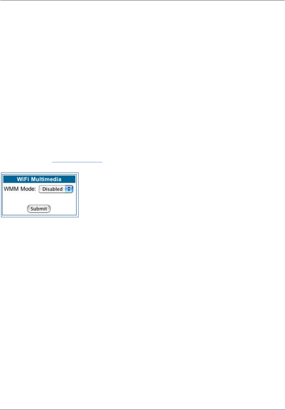
Administrator’s Handbook
62
WiFi Multimedia
WiFi Multimedia is an advanced feature that allows you to prioritize various types of data travelling over the
wireless network. Certain types of data that are sensitive to delays, such as voice or video, must be priori-
tized ahead of other, less delay-sensitive types, such as email.
WiFi Multimedia currently implements wireless Quality of Service (QoS) by transmitting data depending on
Diffserv priority settings. These priorities are mapped into four Access Categories (AC), in increasing order
of priority:
•Background (BK),
•Best Effort (BE),
•Video (VI), and
•Voice (VO).
It requires WiFi Multimedia (WMM)-capable clients, usually a separate feature enabled at the client network
settings, and client PC software that makes use of Differentiated Services (Diffserv). Refer to your operat-
ing system instructions for enabling Diffserv QoS..
When you click the WiFi Multimedia link the WiFi Multimedia page appears.
To enable the WiFi Multimedia custom settings, select Diffserv from the pull-down menu.
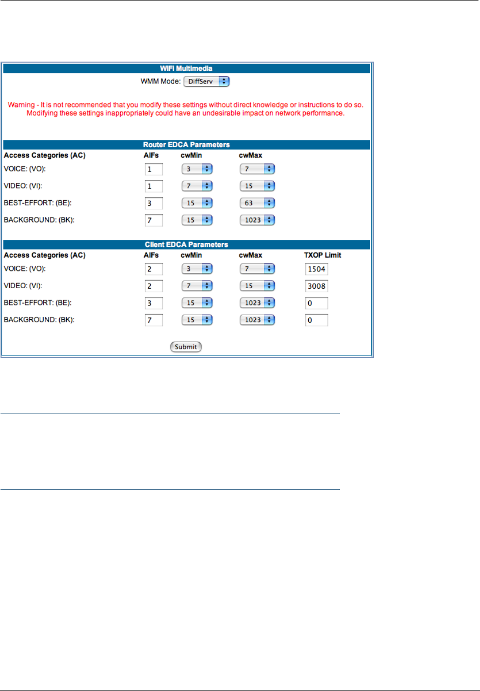
63
The screen expands.
Router EDCA Parameters (Enhanced Distributed Channel Access) govern wireless data from your Gate-
way to the client; Client EDCA Parameters govern wireless data from the client to your Gateway.
☛ NOTE:
It is not recommended that you modify these settings without direct knowledge or instructions
to do so. Modifying these settings inappropriately could seriously degrade network perfor-
mance.
•AIFs: (Arbitration Interframe Spacing) the wait time in milliseconds for data frames.
•cwMin: (Minimum Contention Window) upper limit in milliseconds of the range for determining initial ran-
dom backoff. The value you choose must be lower than cwMax.
•cwMax: (Maximum Contention Window) upper limit in milliseconds of the range of determining final ran-
dom backoff. The value you choose must be higher than cwMin.
•TXOP Limit: Time interval in microseconds that clients may initiate transmissions.
(When Operating Mode is B-only, default values are used and this field is not configurable.)
Wireless MAC Authorization
Wireless MAC Authorization allows you to specify which client PCs are allowed to join the wireless LAN by
specific hardware address. Once it is enabled, only entered MAC addresses that have been set to Allow will
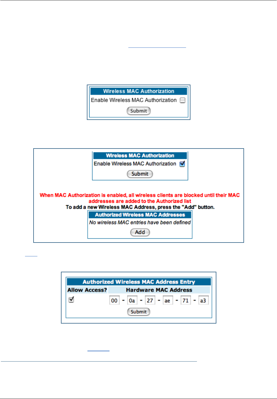
Administrator’s Handbook
64
be accepted onto the wireless LAN. All unlisted addresses will be blocked, in addition to the listed
addresses with Allow disabled.
To enable Wireless MAC Authentication, click the MAC Authorization link.
When the Wireless MAC Authentication screen appears, check the Enable Wireless MAC Authorization
checkbox:
The screen expands as follows:
Click the Add button. The Authorized Wireless MAC Address Entry screen appears.
Enter the MAC (hardware) address of the client PC you want to authorize for access to your wireless LAN.
The Allow Access? checkbox is enabled by default. Unchecking this checkbox specifically denies access
from this MAC address. Click the Submit button.
☛ Note:
When MAC Authorization is enabled, all wireless clients are blocked until their MAC addresses
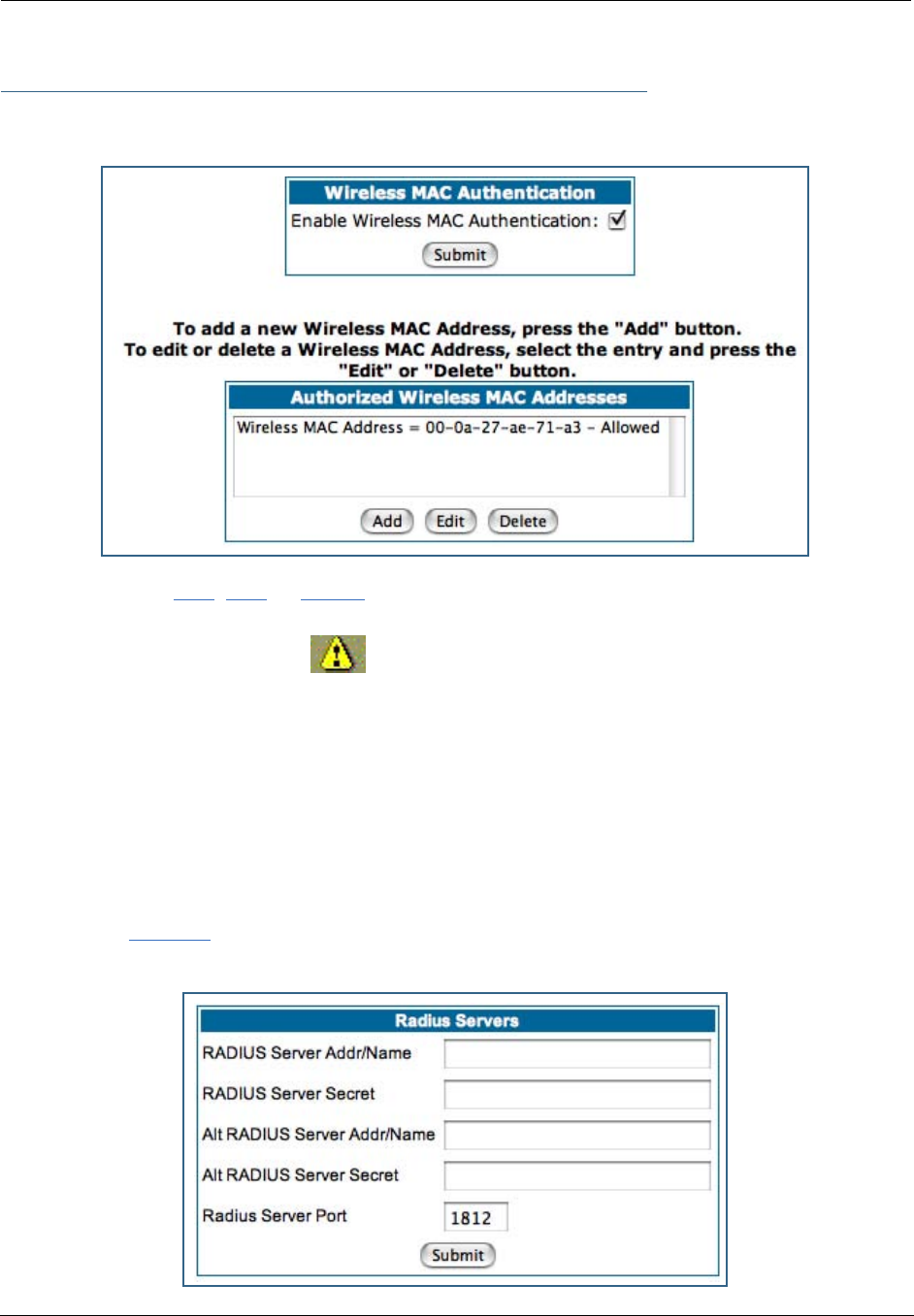
65
are added to the Authorized list.
Your entry will be added to a list of up to 32 authorized addresses as shown:
You can continue to Add, Edit, or Delete addresses to the list by clicking the respective buttons.
After your first entry, the Alert icon will appear in the upper right corner of your screen. When you
are finished adding addresses to the list, click the Alert icon, and Save your changes and restart the Gate-
way.
Use RADIUS Server
RADIUS servers allow external authentication of users by means of a remote authentication database. The
remote authentication database is maintained by a Remote Authentication Dial-In User Service (RADIUS)
server. In conjunction with Wireless User Authentication, you can use a RADIUS server database to authen-
ticate users seeking access to the wireless services, as well as the authorized user list maintained locally
within the Gateway.
If you click the RADIUS link, the screen expands to allow you to enter your RADIUS server information.
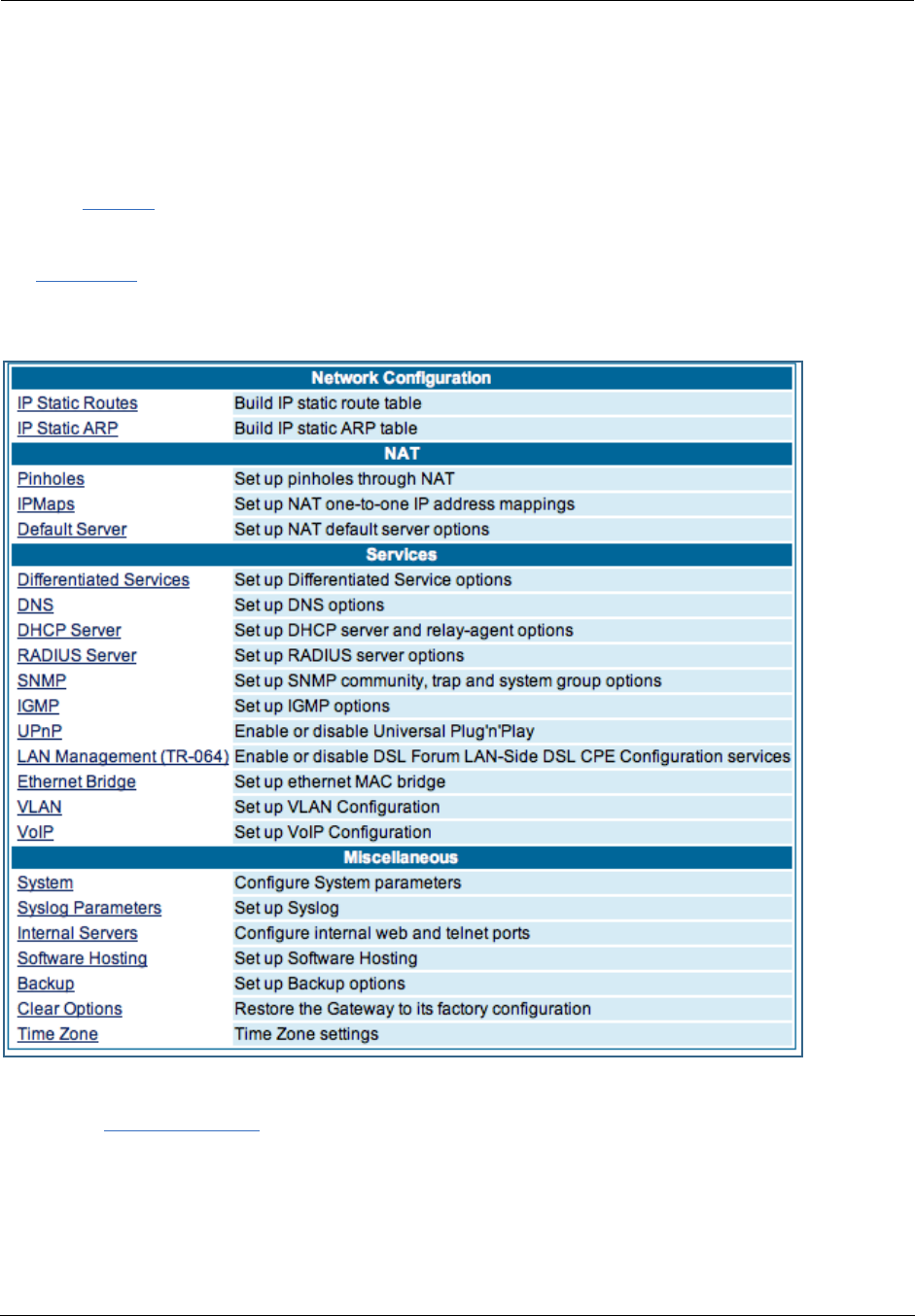
Administrator’s Handbook
66
•RADIUS Server Addr/Name: The default RADIUS server name or IP address that you want to use.
•RADIUS Server Secret: The RADIUS secret key used by this server. The shared secret should have the
same characteristics as a normal password.
•RADIUS Server Port: The port on which the RADIUS server is listening, typically, the default 1812.
Click the Submit button.
You can also configure alternate RADIUS servers from the Advanced Network Configuration page, by clicking
the Advanced link.
The Advanced Network Configuration page appears.
You access the RADIUS Server configuration screen from the Advanced Network Configuration web page, by
clicking the RADIUS Server link.
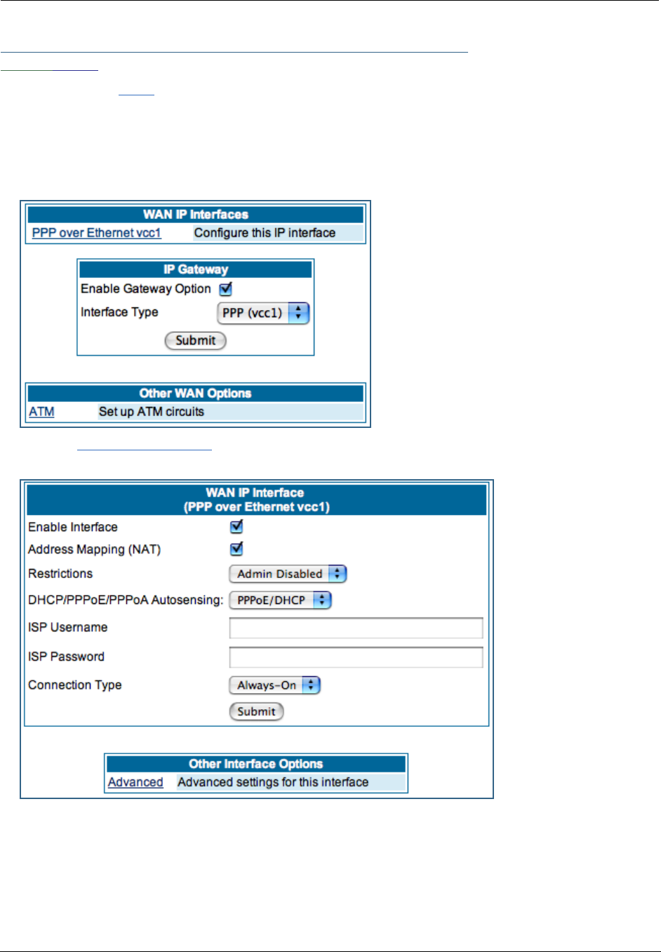
67
Link: WAN
When you click the WAN link, the WAN IP configuration page appears. This page varies depending on the
WAN interface of your Motorola Netopia® Gateway.
WAN IP Interfaces: Your IP interfaces are listed.
PPP over Ethernet interface
Click the PPP over Ethernet link to configure it.
The WAN IP Interface page appears.
Enable Interface: You can disable the interface by unchecking the checkbox. However, doing so will dis-
able all ability for your LAN users to connect to the WAN using the Gateway.
Address Mapping (NAT): Specifies whether you want the Gateway to use network address translation
(NAT) when communicating with remote routers. NAT lets you conceal details of your network from remote
routers. By default, address mapping is enabled.
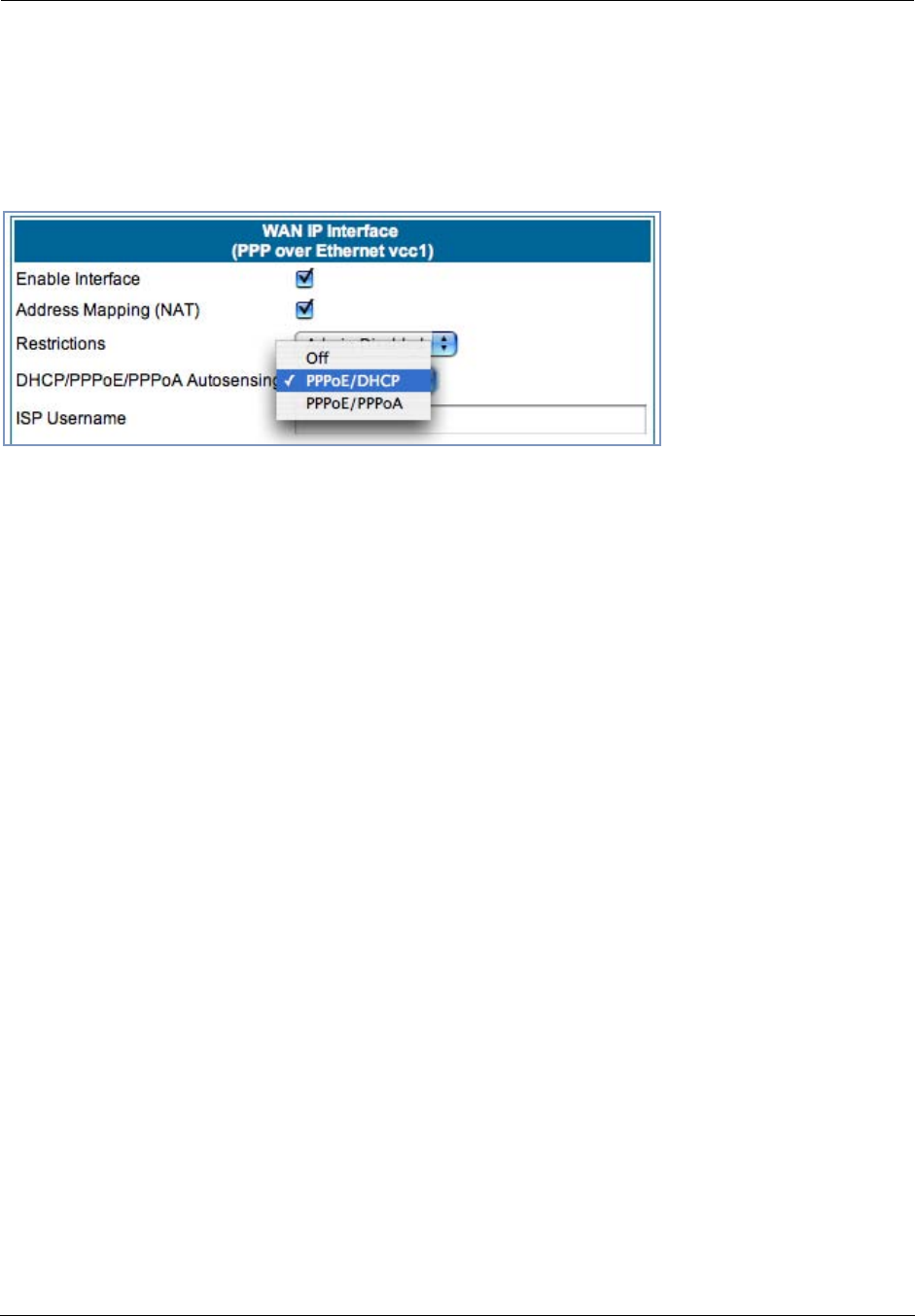
Administrator’s Handbook
68
Restrictions: This setting determines the types of traffic the Gateway accepts from the WAN. Admin Dis-
abled means that Gateway traffic is accepted but administrative commands are ignored. None means that
all traffic is accepted. When PPP is enabled, Admin Disabled is the default.
DHCP/PPPoE/PPPoA Autosensing:
The pull-down menu allows
you to select an autosens-
ing feature, or to disable it.
Selecting between PPPoE/
DHCP or PPPoE/PPPoA
enables automatic sensing
of your WAN connection
type. If you select PPPoE/
DHCP, the gateway
attempts to connect using
PPPoE first. If the Gateway
fails to connect after 60 seconds, it switches to DHCP. As soon as it can connect via DHCP, the Gateway
chooses and sets DHCP as its default. Otherwise, after attempting to connect via DHCP for 60 seconds,
the Gateway switches back to PPPoE. The Gateway will continue to switch back and forth in this manner
until it successfully connects. Similarly, selecting PPPoE/PPPoA causes the Gateway to attempt to con-
nect by trying these protocols in parallel, and using the first one that is successful. If you choose to disable
the feature, select Off.
ISP Username: This is the username used to authenticate your Gateway with the Service Provider's net-
work. This value is given to you by your Service Provider.
ISP Password: This is the password used to authenticate your Gateway with the Service Provider's net-
work. This value is given to you by your Service Provider.
Connection Type: The pull-down menu allows you to choose to have either an uninterrupted connection or
an as-needed connection.
• Always On: This setting provides convenience, but it leaves your network permanently connected to
the Internet.
• Instant On furnishes almost all the benefits of an Always On connection, but has additional security
benefits:
- Your network cannot be attacked when it is not connected.
- Your network may change address with each connection, making it more difficult to attack.
Timeout: (only appears if Instant-On Connection Type is selected) Specifies the time in seconds before dis-
connect if there is no traffic over the Internet link.
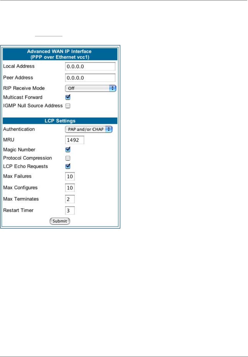
69
Advanced:
If you click the Advanced link, the Advanced WAN IP Interface configuration page appears.
Local Address: If this value is 0.0.0.0, the Gateway
will acquire its IP address from your ISP. Otherwise
this address is assigned to the virtual PPP interface.
Peer Address: Address of the server on the Service
Provider side of the ppp link. This peer will attempt to
negotiate the local IP address if IP Address =
0.0.0.0. If the remote peer does not accept the IP
address, the link will not come up.
RIP Receive Mode: Routing Information Protocol
(RIP) is needed if there are IP routers on other seg-
ments of your Ethernet network that the Motorola
Netopia® Gateway needs to recognize. Set to Off,
Netopia Embedded Software Version 7.7.4 will not
accept information from either RIP-1 nor RIP-2 rout-
ers. With Receive RIP Mode set to RIP-1, the Motor-
ola Netopia® Gateway will accept routing information
provided by RIP packets from other routers that use
the same subnet mask. Set to RIP-2, Netopia
Embedded Software Version 7.7.4 will accept routing
information provided by RIP packets from other rout-
ers that use different subnet masks.
From the pull-down menu, choose Off, RIP-1, RIP-2,
RIP-1 compatibility, or RIP-2 with MD5.
RIP Receive MD5 Key: (Only appears if RIP-2 with
MD5 RIP Receive Mode is selected) The purpose of MD5 authentication is to provide an additional level of
confidence that a RIP packet received was generated by a reliable source. In other words, MD5 authentica-
tion provides an enhanced level of security that information that your PC receives does not originate from a
malicious source posing as part of your network. This field allows you to enter an MD5 encryption key of
from 1 – 16 ASCII characters for authenticating RIP receipts.
Multicast Forward: If you check this checkbox, this interface acts as an IGMP proxy host, and IGMP pack-
ets are transmitted and received on this interface on behalf of IGMP hosts on the LAN interface.
IGMP Null Source Address: If you check this checkbox, the source IP address of every IGMP packet trans-
mitted from this interface is set to 0.0.0.0. This complies with the requirements of TR-101, and removes
the need for a publicly advertised IP address on the WAN interface. This checkbox is only available if “Mul-
ticast Forward” is checked.
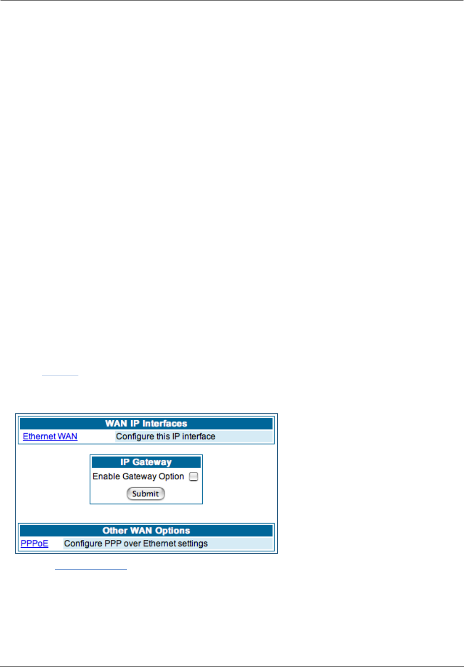
Administrator’s Handbook
70
LCP Settings:
Authentication: Select Off, PAP and/or CHAP, PAP only, or CHAP only from the pull-down menu. The
settings for port authentication on the Gateway must match the authentication expected by the remote sys-
tem. The username and passwords are available on the WAN IP Interfaces page.
MRU: Specifies the Maximum Receive Unit for the PPP Interface.
Magic Number: Enables or disables LCP magic number negotiation.
Protocol Compression: Specifies whether you want the Gateway to compress the PPP Protocol field when
it transmits datagrams over the PPP link.
LCP Echo Requests: Specifies whether you want your Gateway to send LCP echo requests. You should
turn off LCP echoing if you do not want the Gateway to drop a PPP link to a nonresponsive peer.
Max Failures: Specifies the maximum number of Configure-NAK messages the PPP module can send with-
out having sent a Configure-ACK message.
Max Configures: Specifies the maximum number of unacknowledged configuration requests that your
Gateway will send.
Max Terminates: Specifies the maximum number of unacknowledged termination requests that your Gate-
way will send before terminating the PPP link.
Restart Timer: The number of seconds the Gateway should wait before retransmitting a configuration or
termination request.
Click the Submit button when you are finished.
Ethernet WAN interface
Click the Ethernet WAN link to configure it.
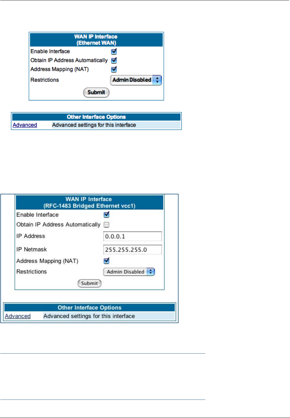
71
The WAN IP Interface page appears.
Enable Interface: You can disable the interface by unchecking the checkbox. However, doing so will dis-
able all ability for your LAN users to connect to the WAN using the Gateway.
Obtain IP Address Automatically: Your service provider may tell you that the WAN IP Address for your
Gateway is static. In this case, disable this checkbox and enter the IP Address and IP Netmask from your
Service Provider in the appropriate fields.
IP Address: This is the IP Address from your Service Provider when using static IP addressing.
IP Netmask: This is the Netmask from your Service Provider when using static IP addressing.
☛ NOTE:
Beginning with Firmware Version 7.7, you can now run an IPoE interface without an IP address
(“unnumbered” interface), if you un-check “Obtain IP Address Automatically” and set the IP
Address to 0.
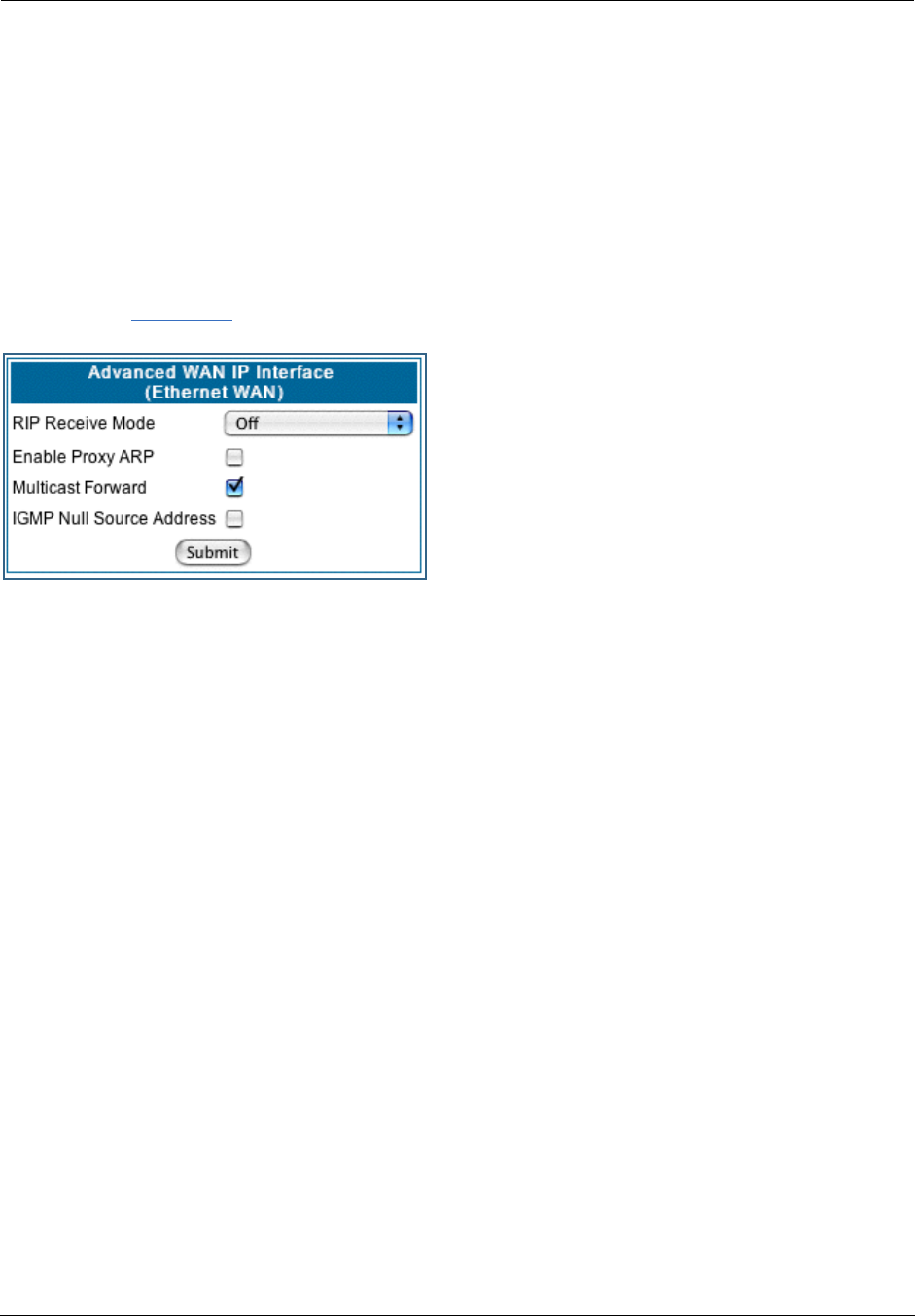
Administrator’s Handbook
72
Address Mapping (NAT): Specifies whether you want the Gateway to use network address translation
(NAT) when communicating with remote routers. NAT lets you conceal details of your network from remote
routers. By default, address mapping is enabled.
Restrictions: This setting determines the types of traffic the Gateway accepts from the WAN. Admin Dis-
abled means that Gateway traffic is accepted but administrative commands are ignored. None means that
all traffic is accepted. Admin Disabled is the default.
Advanced:
If you click the Advanced link the Advanced WAN IP Interface configuration page appears.
RIP Receive Mode: Routing Information Protocol (RIP)
is needed if there are IP routers on other segments of
your Ethernet network that the Motorola Netopia® Gate-
way needs to recognize. Set to Off, Netopia Embedded
Software Version 7.7.4 will not accept information from
either RIP-1 nor RIP-2 routers. With Receive RIP Mode
set to RIP-1, the Motorola Netopia® Gateway will
accept routing information provided by RIP packets from
other routers that use the same subnet mask. Set to
RIP-2, Netopia Embedded Software Version 7.7.4 will
accept routing information provided by RIP packets from
other routers that use different subnet masks.
From the pull-down menu, choose Off, RIP-1, RIP-2, RIP-1 compatibility, or RIP-2 with MD5.
Enable Proxy ARP: Checking the checkbox will enable the Gateway to respond when it receives an
Address Resolution Protocol message for devices behind it.
Multicast Forward: If you check this checkbox, this interface acts as an IGMP proxy host, and IGMP pack-
ets are transmitted and received on this interface on behalf of IGMP hosts on the LAN interface.
IGMP Null Source Address: If you check this checkbox, the source IP address of every IGMP packet trans-
mitted from this interface is set to 0.0.0.0. This complies with the requirements of TR-101, and removes
the need for a publicly advertised IP address on the WAN interface. This checkbox is only available if “Mul-
ticast Forward” is checked.
IP Gateway
Enable Gateway Option: You can configure the Gateway to send packets to a default gateway if it does
not know how to reach the destination host.
Interface Type: If you have PPPoE enabled, you can specify that packets destined for unknown hosts
will be sent to the gateway being used by the remote PPP peer. If you select ip-address, you must enter
the IP address of a host on a local or remote network to receive the traffic.
Default Gateway: The IP Address of the default gateway.
Other WAN Options
PPPoE: You can enable or disable PPPoE. This link also allows configuration of NAT, admin restrictions,
PPPoE username/password, and connection type.
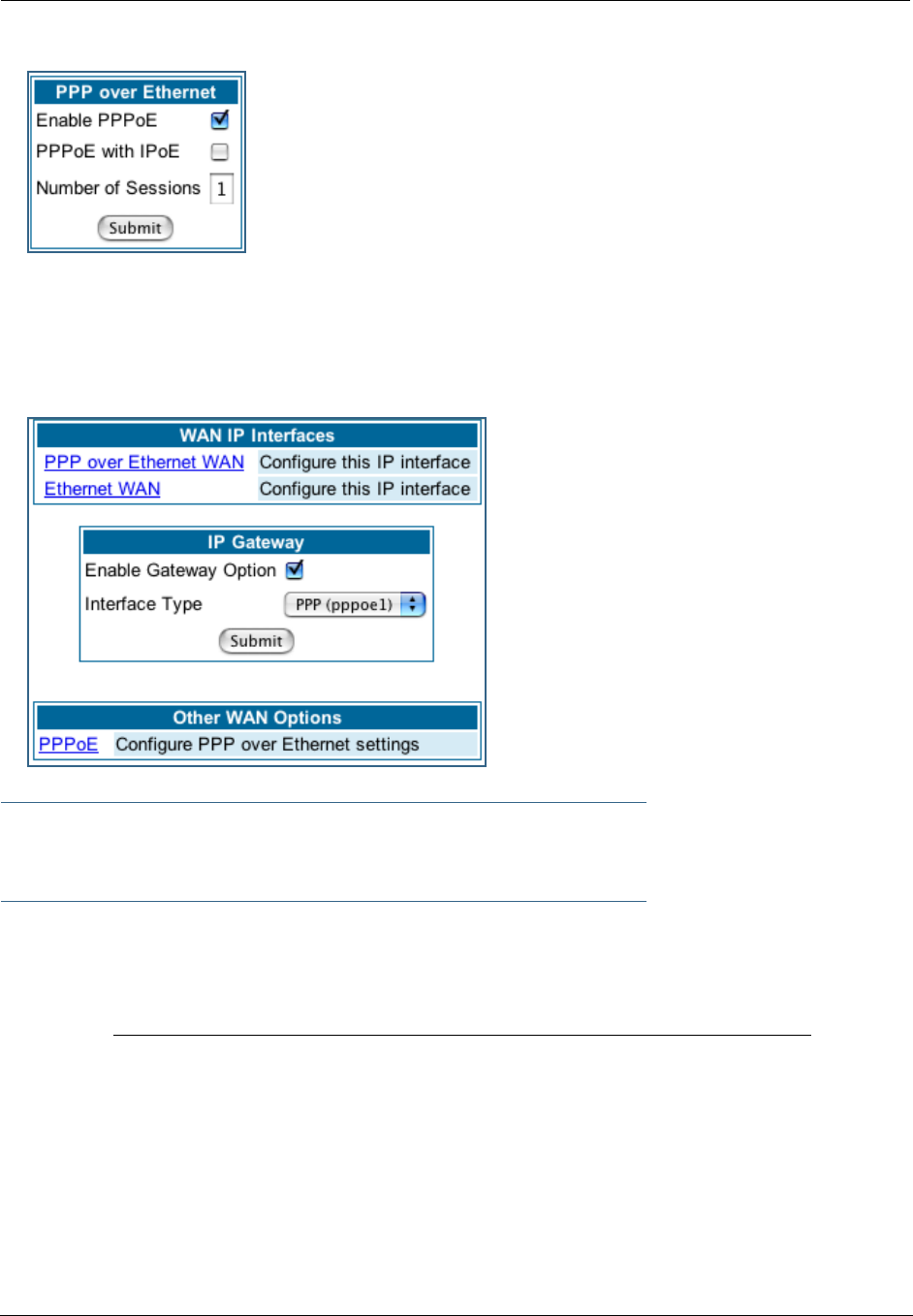
73
WAN Ethernet and VDSL Gateways
To allow for concurrent PPPoE and IPoE support on WAN Ethernet Gateways, including VDSL units,
PPPoE with IPoE is available on the PPPoE configuration page. Checking the checkbox will provide this
concurrent support. When you enable PPPoE with IPoE, the additional WAN interface becomes available
for configuration.
☛ NOTE:
Enabling pppoe-with-ipoe disables support for multiple PPPoE sessions.
ADSL Gateways
ATM Circuits: You can configure the ATM circuits and the number of Sessions. The IP Inter face(s)
should be reconfigured after making changes here.
Available Encapsulation types: Available Multiplexing types:
PPP over Ethernet (PPPoE) LLC/SNAP
PPP over ATM (PPPoA) VC muxed
RFC-1483 Bridged Ethernet
RFC-1483 Routed IP
None
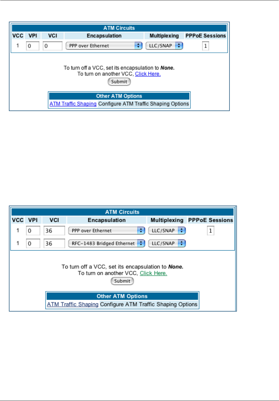
Administrator’s Handbook
74
Your Motorola Netopia® ADSL Gateway supports VPI/VCI autodetection by default. If VPI/VCI autodetec-
tion is enabled, the ATM Circuits page displays VPI/VCI = 0. If you configure a new ATM VPI/VCI pair,
upon saving and restarting, autodetection is disabled and only the new VPI/VCI pair configuration will be
enabled.
VPI/VCI Autodetection consists of eight static VPI/VCI pair configurations. These are 0/35, 8/35, 0/32,
8/32, 1/35, 1/1, 1/32, 2/32. These eight VPI/VCI pairs will be created if the Gateway is configured for
autodetection. the Gateway does not establish a circuit using any of these preconfigured VPI/VCI pairs,
then you can manually enter a VPI/VCI pair in the ATM Circuits page.
PPPoE with IPoE: For ADSL Gateways, you must configure two VCCs with the same VPI/VCI settings to
provide concurrent PPPoE with IPoE support.
You must use fixed VPI/VCI values for PPPoE with IPoE. You cannot have both VPI/VCI values set to 0/0;
autodetection does not work in this mode.
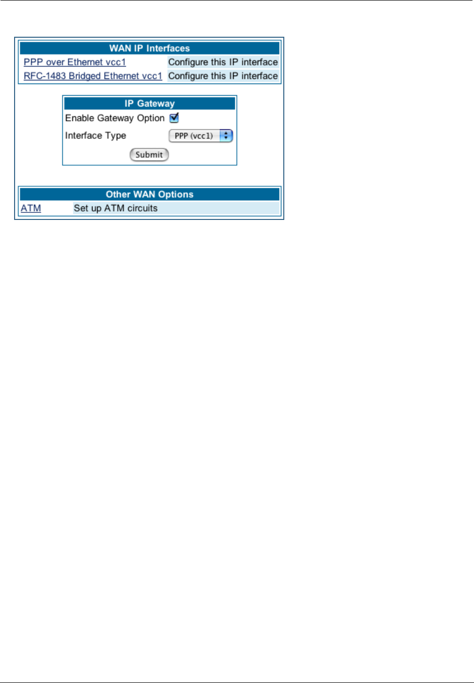
75
Once the VCCs have been configured,
the WAN IP Interfaces screen displays
the additional interface which you can
then configure as required.
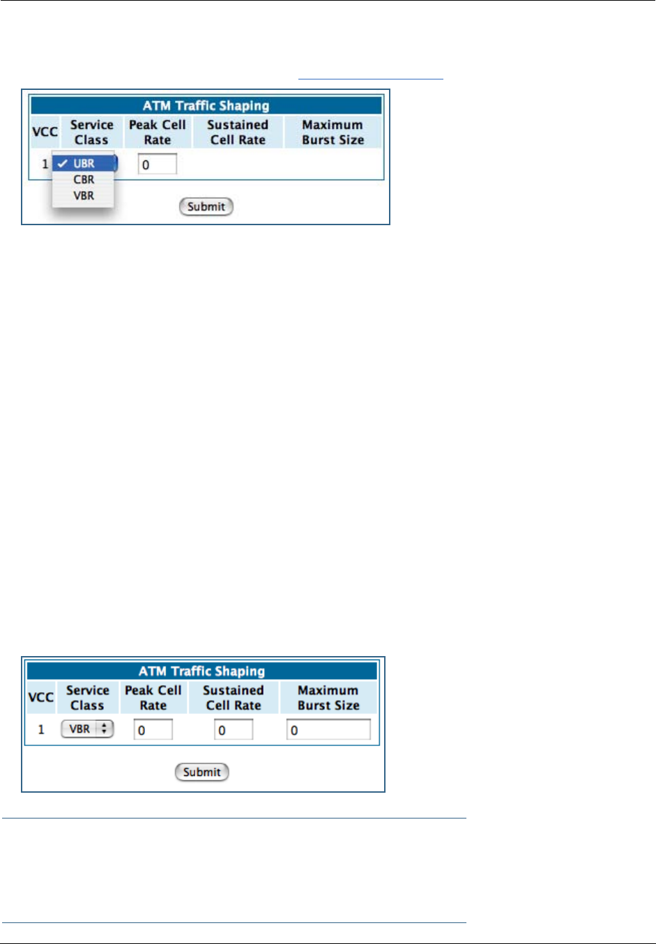
Administrator’s Handbook
76
ATM Traffic Shaping: You can prioritize delay-sensitive data by configuring the Quality of Service (QoS)
characteristics of the virtual circuit. Click the ATM Traffic Shaping link.
You can choose UBR (Unspecified Bit Rate), CBR (Constant Bit Rate), or VBR (Variable Bit Rate) from the
pull-down menu and set the Peak Cell Rate (PCR) in the editable field.
UBR (Unspecified Bit Rate) guarantees no minimum transmission rate. Cells are transmitted on a
“best effort” basis. However, there is a cap on the maximum transmission rate for UBR VCs. In a practi-
cal situation:
• UBR VCs should be transmitted at a priority lower than CBR.
• Bandwidth should be shared equally among UBR VCs.
UBR applications are non-real-time traffic such as IP data traffic.
CBR (Constant Bit Rate) guarantees a certain transmission rate (although the application may
underutilize this bandwidth). A Peak Cell Rate (PCR) characterizes CBR. CBR is most suited for real time
applications such as real time voice / video, although it can be used for other applications.
VBR (Variable Bit Rate) This class is characterized by:
• a Peak Cell Rate (PCR), which is a temporary burst, not a sustained rate, and
• a Sustained Cell Rate (SCR),
• a Burst Tolerance (BT), specified in terms of Maximum Burst Size (MBS). The MBS is the maximum
number of cells that can be transmitted at the peak cell rate and should be less than, or equal to the
Peak Cell Rate, which should be less than, or equal to the line rate.
VBR has two sub-classes:
a. VBR non-real-time (VBR-nrt): Typical applications are non-real-time traffic, such as IP data traffic. This
class yields a fair amount of Cell Delay Variation (CDV).
b. VBR real time (VBR-rt): Typical applications are real-time traffic, such as compressed voice over IP
and video conferencing. This class transmits cells with a more tightly bounded Cell Delay Variation. The
applications follow CBR.
☛ Note:
The difference between VBR-rt and VBR-nrt is the tolerated Cell Delay Variation range and the
provisioned Maximum Burst Size.

77
Class PCR SCR MBS Transmit Priority Comments
UBR X N/A N/A Low PCR is a cap
CBR X N/A N/A High PCR is a guaranteed rate
VBR X X X High PCR > SCR.
SCR is a guaranteed rate.
PCR is a cap.
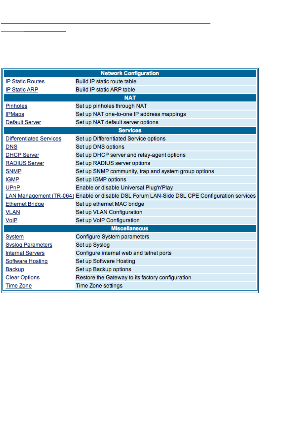
Administrator’s Handbook
78
Link: Advanced
Selected Advanced options are discussed in the pages that follow. Many are self-explanatory or are dic-
tated by your service provider.
The following are typical links under Configure -> Advanced (some models offer other links):
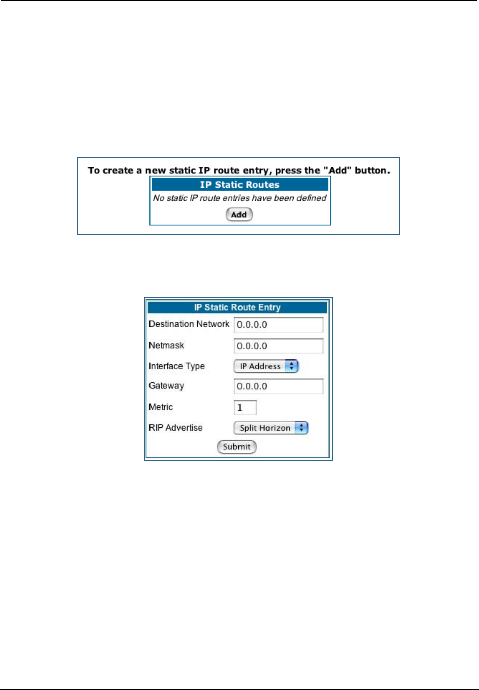
79
Link: IP Static Routes
A static route identifies a manually configured pathway to a remote network. Unlike dynamic routes, which
are acquired and confirmed periodically from other routers, static routes do not time out. Consequently,
static routes are useful when working with PPP, since an intermittent PPP link may make maintenance of
dynamic routes problematic.
When you click the Static Routes link, the IP Static Routes page appears.
You can configure as many as 32 static IP routes for the Gateway. To add a static route, click the Add but-
ton.
The IP Static Route Entry page appears.
•Destination Network: Enter the IP address of the static route. It may not be 0.0.0.0.
•Netmask: Enter the subnet mask for the IP network at the other end of the static route. The subnet
mask associated with the destination network must represent the same network class (A, B, or C) or a
lower class (such as a class C subnet mask or class B network number) to be valid.
•Interface Type: Choose PPP (vcc1) – depending on the interface; typically vcc1 for DSL – or IP Address
from the pull-down menu to specify whether the static route is accessible through PPP or IP address.
•Gateway: Enter the IP address of the gateway for the static route. The default gateway must be located
on a network connected to your Motorola Netopia® Gateway configured interface.
•Metric: Specifies the hop count for the static route. Enter a number from 1 to 15 to indicate the number
of routes (actual or best guess) a packet must traverse to reach the remote network. Some metric or a
value of 1 will be used to indicate:
• The remote network is one router away and the static route is the best way to
reach it.
• The remote network is more than one router away but the static route should not
be replaced by a dynamic route, even if the dynamic route is more efficient.
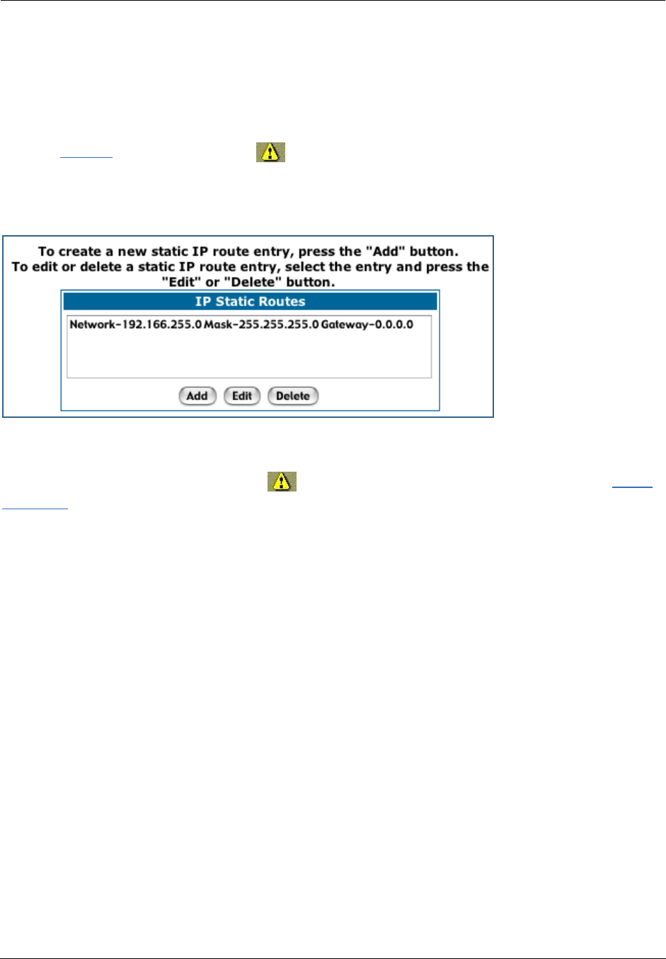
Administrator’s Handbook
80
•RIP Advertise: From the pull-down menu, choose how the static route should be advertised via RIP:
• Split Horizon: Do not advertise route if the gateway is on the same subnet.
• Always: Advertise route in all RIP messages.
• Never: Do not advertise route.
Click the Submit button. The Alert icon will appear, so that you can switch to the Save Changes
page, when you are finished.
Once you save your changes, you will be returned to the IP Static Routes entry screen.
•You can continue to Add, Edit, or Delete Static Routes from this screen.
When you are finished, click the Alert icon , switch to the Save Changes page, and click the Save
Changes link.
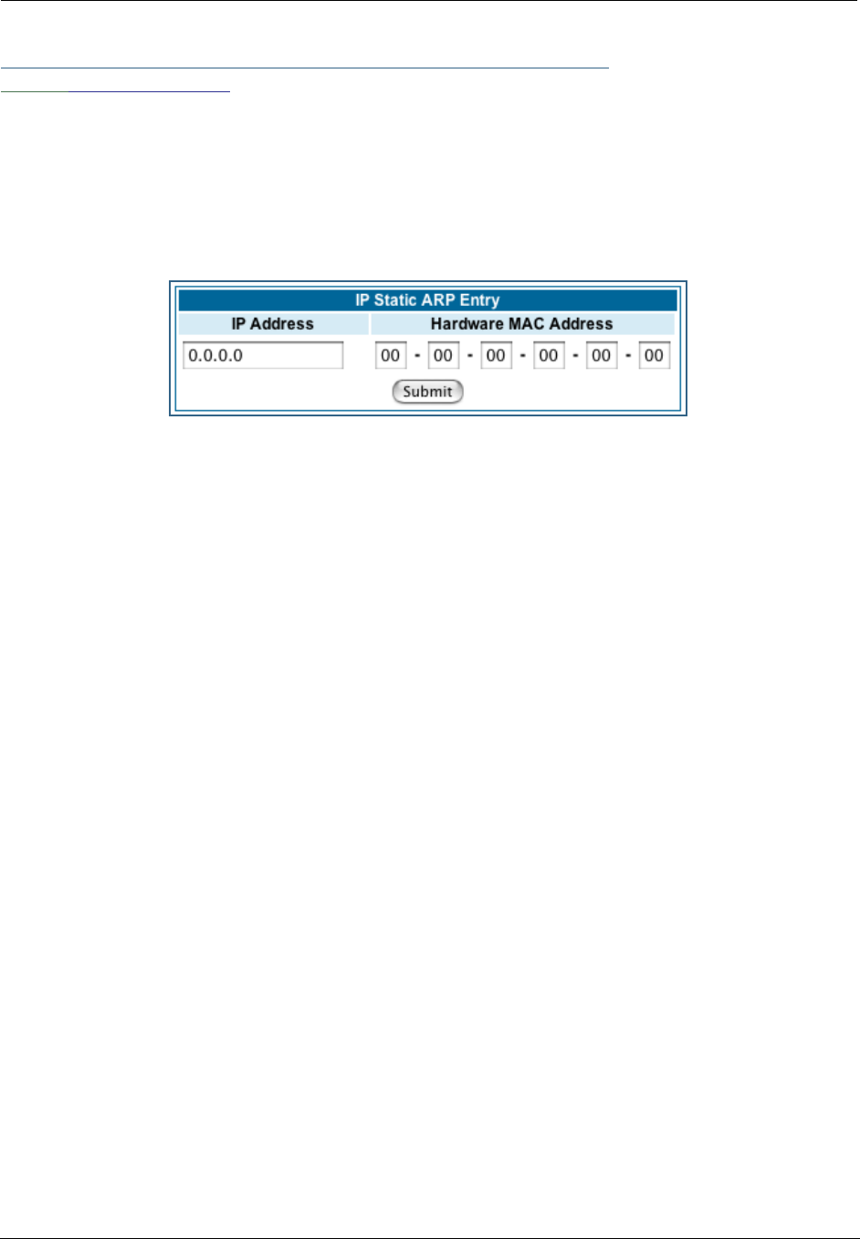
81
Link: IP Static ARP
Your Gateway maintains a dynamic Address Resolution Protocol (ARP) table to map IP addresses to Ether-
net (MAC) addresses. It populates this ARP table dynamically, by retrieving IP address/MAC address pairs
only when it needs them. Optionally, you can define static ARP entries to map IP addresses to their corre-
sponding Ethernet MAC addresses. Unlike dynamic ARP table entries, static ARP table entries do not time
out. The IP address cannot be 0.0.0.0. The Ethernet MAC address entry is in nn-nn-nn-nn-nn-nn (hexadeci-
mal) format.
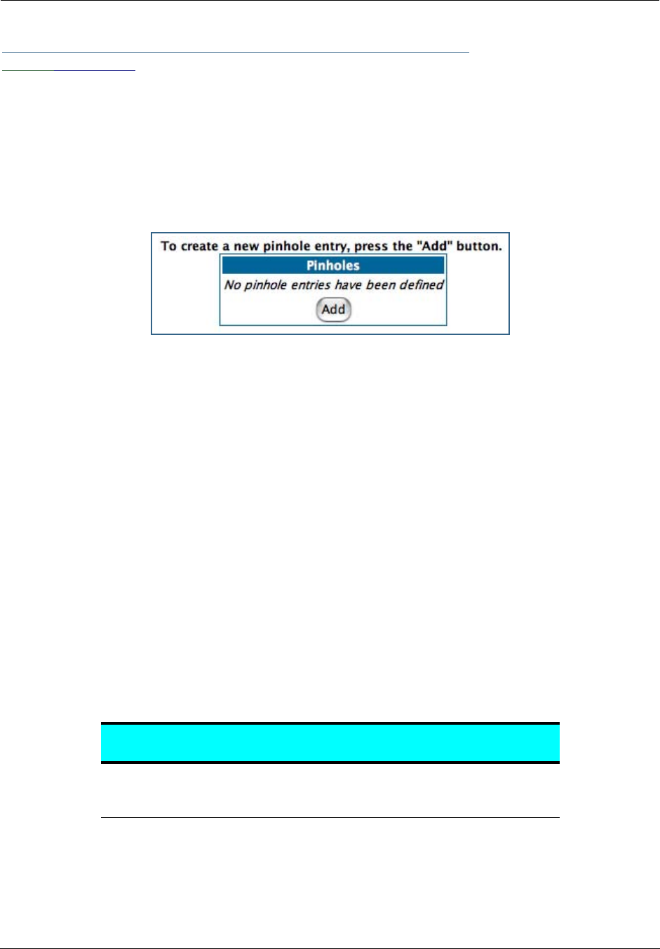
Administrator’s Handbook
82
Link: Pinholes
Pinholes allow you to transparently route selected types of network traffic, such as FTP requests or HTTP
(Web) connections, to a specific host behind the Gateway. Creating a pinhole allows access traffic originat-
ing from a remote connection (WAN) to be sent to the internal computer (LAN) that is specified in the Pin-
hole page.
Pinholes are common for applications like multiplayer online games. Refer to software manufacturer appli-
cation documentation for specific traffic types and port numbers.
Configure Specific Pinholes. Planning for Your Pinholes. Determine if any of the service
applications that you want to provide on your LAN stations use TCP or UDP protocols. If an application does,
then you must configure a pinhole to implement port forwarding. This is accessed from the Advanced ->
Pinholes page.
Example: A LAN Requiring Three Pinholes . The procedure on the following pages describes
how you set up your NAT-enabled Motorola Netopia® Gateway to support three separate applications. This
requires passing three kinds of specific IP traffic through to your LAN.
Application 1
: You have a Web server located on your LAN behind your Motorola Netopia® Gateway and
would like users on the Internet to have access to it. With NAT “On”, the only externally visible IP address
on your network is the Gateway’s WAN IP (supplied by your Service Provider). All traffic intended for that LAN
Web server must be directed to that IP address.
Application 2
: You want one of your LAN stations to act as the “central repository” for all email for all of
the LAN users.
Application 3
: One of your LAN stations is specially configured for game applications. You want this spe-
cific LAN station to be dedicated to games.
A sample table to plan the desired pinholes is:
For this example, Internet protocols TCP and UDP must be passed through the NAT security feature and the
Gateway’s embedded Web (HTTP) port must be re-assigned by configuring new settings on the Internal
Servers page.
WAN Traffic Type Protocol Pinhole Name LAN Internal IP
Address
Web TCP my-webserver 192.168.1.1
Email TCP my-mailserver 192.168.1.2
Games UDP my-games 192.168.1.3
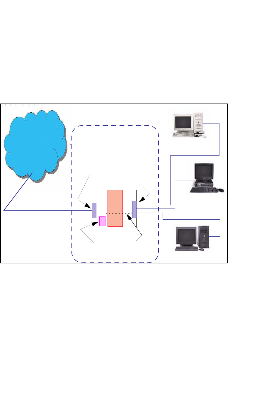
83
☛ TIPS for making Pinhole Entries:
1. If the port forwarding feature is required for Web services, ensure that the embedded Web
server’s port number is re-assigned PRIOR to any Pinhole data entry.
2. Enter data for one Pinhole at a time.
3. Use a unique name for each Pinhole. If you choose a duplicate name, it will overwrite the
previous information without warning.
A diagram of this LAN example is:
You can also use the LAN-side address of the Gateway, 192.168.1.x:8100 to access the web and
192.168.1.x:23 to access the telnet server.
WAN
LAN
Ethernet
Interface
192.168.1.1
192.168.1.2
192.168.1.3
my-webserver
my-mailserver
my-games
Gateway
NAT
NAT Pinholes
Embedded
Web Server
210.219.41.20
210.219.41.20:8100
Ethernet
Interface
Internet
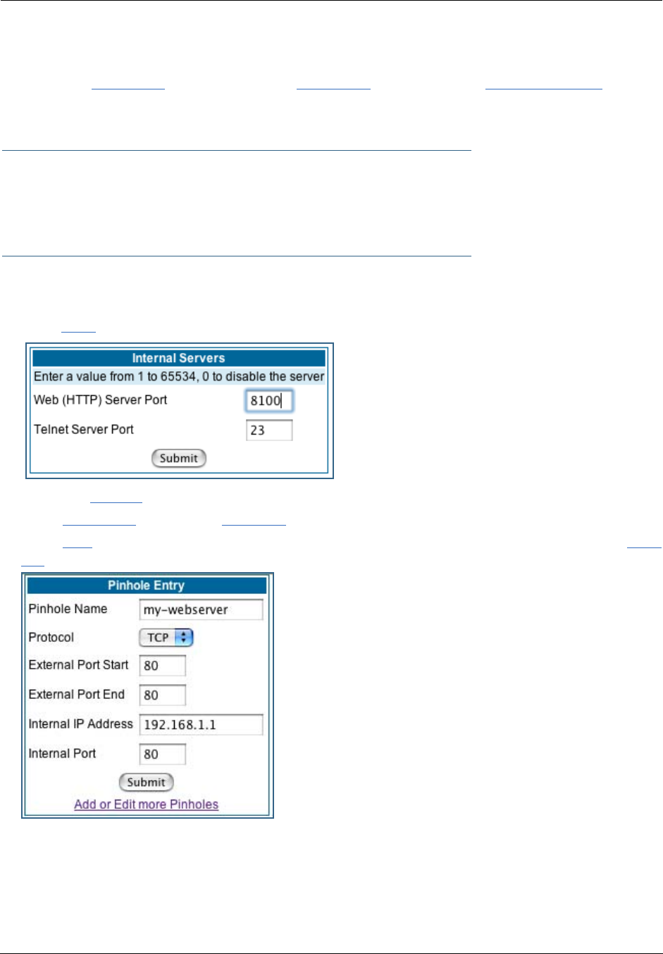
Administrator’s Handbook
84
Pinhole Configuration Procedure. Use the following steps:
1. From the Configure toolbar button -> Advanced link, select the Internal Servers link.
Since Port Forwarding is required for this example, the Motorola Netopia® embedded Web server is con-
figured first.
☛ NOTE:
The two text boxes, Web (HTTP) Server Port and Telnet Server Port, on this page refer to
the port numbers of the Motorola Netopia® Gateway’s embedded administration ports.
To pass Web traffic through to your LAN station(s), select a Web (HTTP) Port number that is greater than
1024. In this example, you choose 8100.
2. Type 8100 in the Web (HTTP) Server Port text box.
3. Click the Submit button.
4. Click Advanced. Select the Pinholes link to go to the Pinhole page.
5. Click Add. Type your specific data into the Pinhole Entries table of this page. Click Sub-
mit.
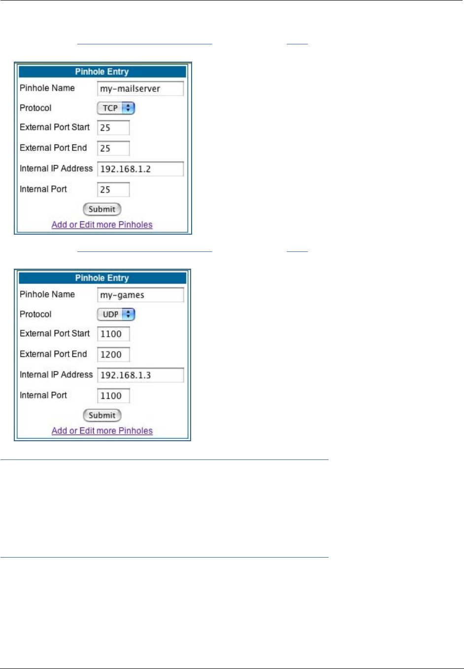
85
6. Click on the Add or Edit more Pinholes link. Click the Add button. Add the next Pinhole.
Type the specific data for the second Pinhole.
7. Click on the Add or Edit more Pinholes link. Click the Add button. Add the next Pinhole.
Type the specific data for the third Pinhole.
☛ NOTE:
Note the following parameters for the “my-games” Pinhole:
1. The Protocol ID is UDP.
2. The external port is specified as a range.
3. The Internal port is specified as the lower range entry.
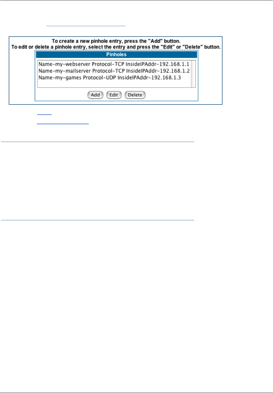
Administrator’s Handbook
86
8. Click on the Add or Edit more Pinholes link. Review your entries to be sure they are cor-
rect.
9. Click the Alert icon.
10. Click the Save and Restart link to complete the entire Pinhole creation task and ensure
that the parameters are properly saved.
☛ NOTE:
REMEMBER: When you have re-assigned the port address for the embedded Web server, you
can still access this facility.
Use the Gateway’s WAN address plus the new port number.
In this example it would be
<WAN Gateway address>:<new port number> or, in this case, 210.219.41.20:8100
You can also use the LAN-side address of the Gateway, 192.168.1.x:8100 to access the web
and 192.168.1.x:23 to access the telnet server.
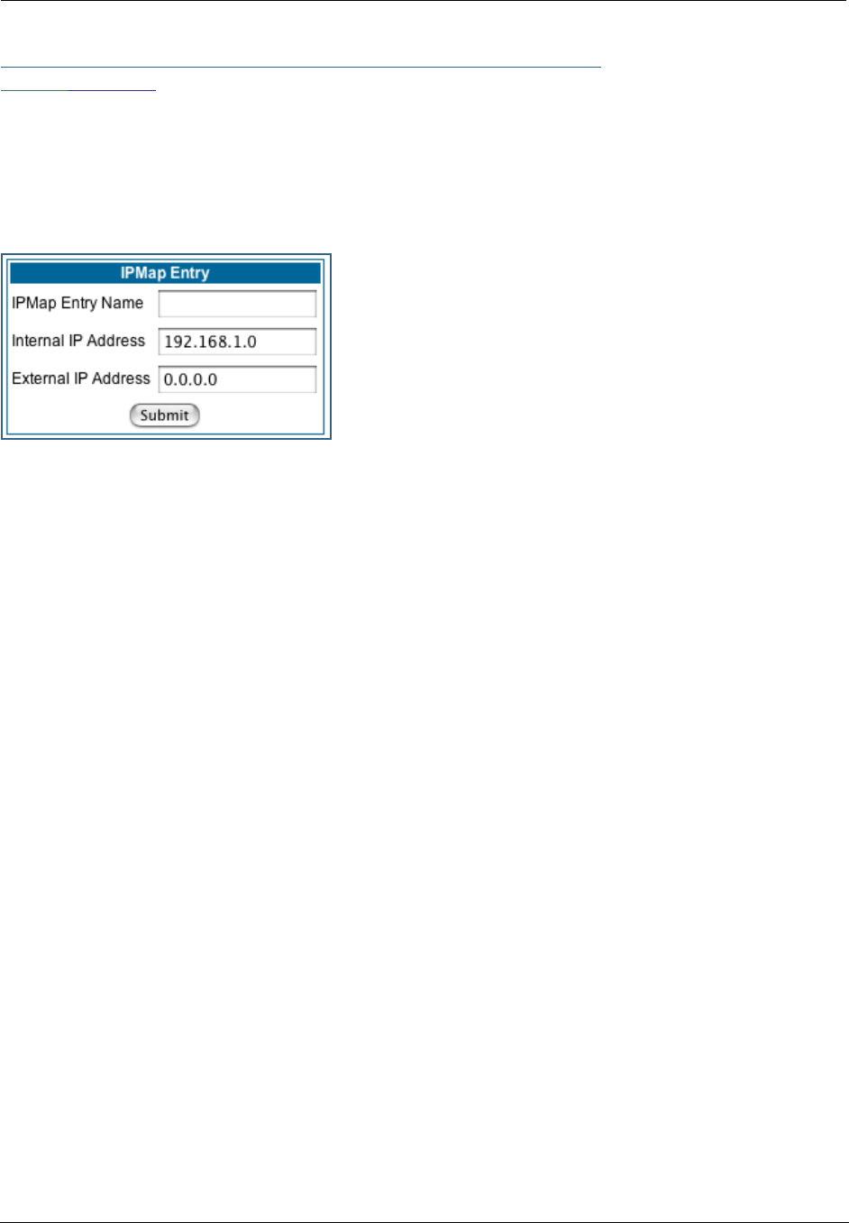
87
Link: IPMaps
IPMaps supports one-to-one Network Address Translation (NAT) for IP addresses assigned to servers,
hosts, or specific computers on the LAN side of the Motorola Netopia® Gateway.
A single static or dynamic (DHCP) WAN IP address must be assigned to support other devices on the LAN.
These devices utilize Motorola Netopia®’s default NAT/PAT capabilities.
Configure the IPMaps Feature
FAQs for the IPMaps Feature
Before configuring an example of an IPMaps-enabled network, review these frequently asked questions.
What are IPMaps and how are they used? The IPMaps feature allows multiple static WAN IP
addresses to be assigned to the Motorola Netopia® Gateway.
Static WAN IP addresses are used to support specific services, like a web server, mail server, or DNS
server. This is accomplished by mapping a separate static WAN IP address to a specific internal LAN IP
address. All traffic arriving at the Gateway intended for the static IP address is transferred to the internal
device. All outbound traffic from the internal device appears to originate from the static IP address.
Locally hosted servers are supported by a public IP address while LAN users behind the NAT-enabled IP
address are protected.
IPMaps is compatible with the use of NAT, with either a statically assigned IP address or DHCP/PPP served
IP address for the NAT table.
What types of servers are supported by IPMaps? IPMaps allows a Motorola Netopia® Gate-
way to support servers behind the Gateway, for example, web, mail, FTP, or DNS servers. VPN servers are
not supported at this time.
Can I use IPMaps with my PPPoE or PPPoA connection? Yes. IPMaps can be assigned to
the WAN interface provided they are on the same subnet. Service providers will need to ensure proper
routing to all IP addresses assigned to your WAN interface.
Will IPMaps allow IP addresses from different subnets to be assigned to my Gate-
way? IPMap will support statically assigned WAN IP addresses from the same subnet.
WAN IP addresses from different subnets are not supported.
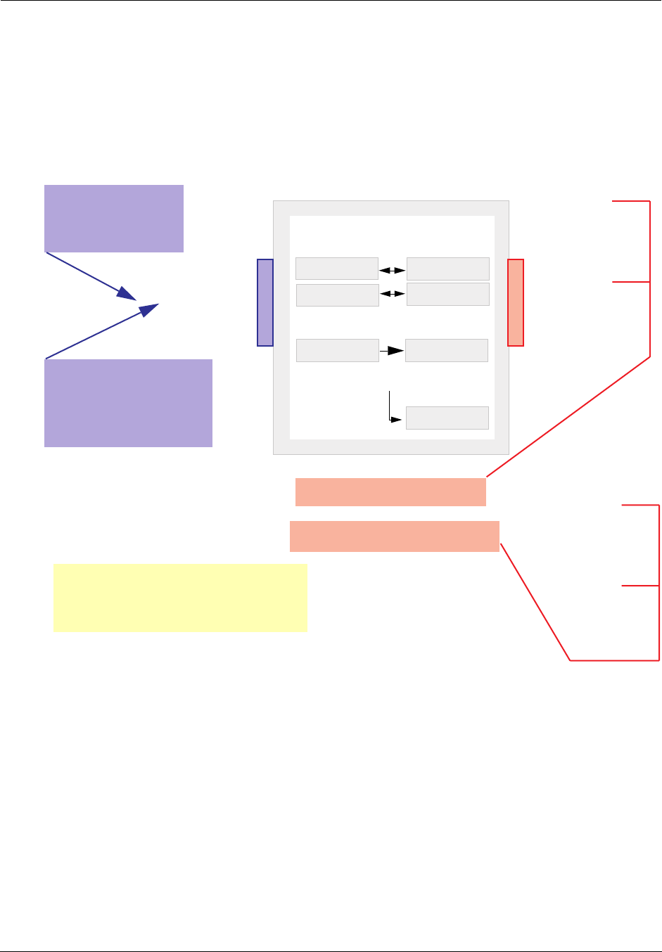
Administrator’s Handbook
88
IPMaps Block Diagram
The following diagram shows the IPMaps principle in conjunction with existing Motorola Netopia® NAT oper-
ations:
NAT/PAT Table
143.137.50.37
143.137.50.36
143.137.50.35
192.168.1.1
192.168.1.n
192.168.1.3
192.168.1.2
...
...
Motorola Netopia® Gateway
Static IP Addresses
for IPMaps Applications
143.137.50.37
143.137.50.36
143.137.50.35
Static IP Addresses
or
DHCP/PPP Served IP Address
for Netopia’s default NAT/PAT
Capabilities
IPMaps:
One-to-One
Multiple Address Mapping
LAN stations with WAN IP traffic
forwarded by Netopia’s IPMaps
LAN stations with WAN IP traffic
forwarded by Netopia’s NAT function.
WAN Interface LAN Interface
192.168.1.1
192.168.1.2
192.168.1.3
192.168.1.n
.
.
.
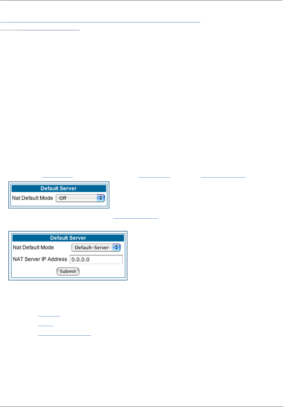
89
Link: Default Server
This feature allows you to:
•Direct your Gateway to forward all externally initiated IP traffic (TCP and UDP protocols only) to a default
host on the LAN.
Enable it for certain situations:
– Where you cannot anticipate what port number or packet protocol an in-bound application might
use. For example, some network games select arbitrary port numbers when a connection is
opened.
– When you want all unsolicited traffic to go to a specific LAN host.
•Configure for IP Passthrough.
Configure a Default Server. This feature allows you to direct unsolicited or non-specific traffic to a
designated LAN station. With NAT “On” in the Gateway, these packets normally would be discarded.
For instance, this could be application traffic where you don’t know (in advance) the port or protocol that
will be used. Some game applications fit this profile.
Use the following steps to setup a NAT default server to receive this information:
1. Select the Configure toolbar button, then Advanced, then the Default Server link.
2. From the pull-down menu, select Default-Server.
The NAT Server IP Address field appears.
3. Determine the IP address of the LAN computer you have chosen to receive the unex-
pected or unknown traffic.
Enter this address in the NAT Server IP Address field.
4. Click the Submit button.
5. Click the Alert button.
6. Click the Save and Restart link to confirm.
Typical Network Diagram. A typical network using the NAT Default Server looks like this:
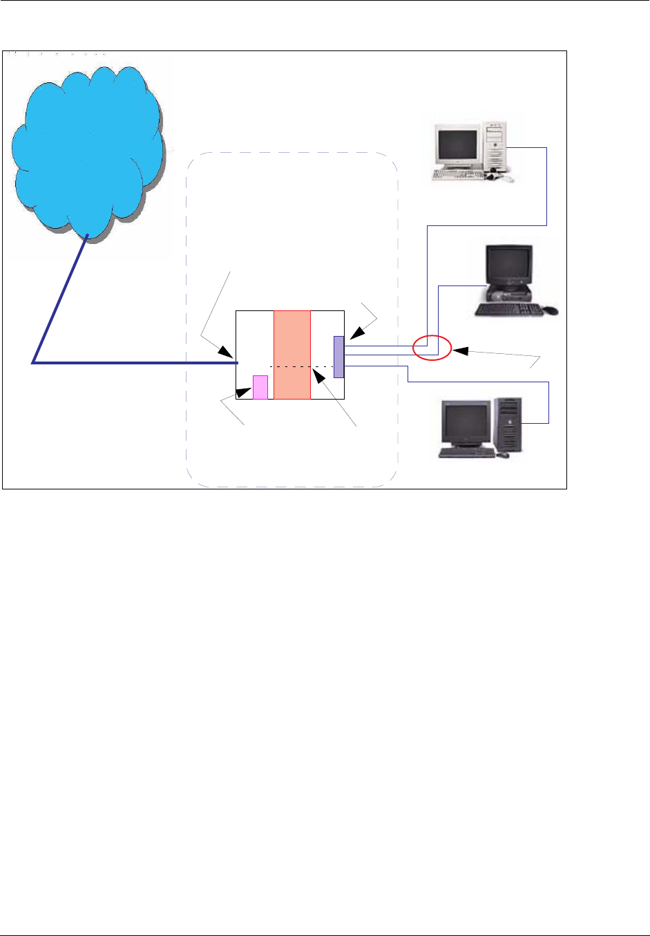
Administrator’s Handbook
90
You can also use the LAN-side address of the Gateway, 192.168.1.x to access the web and telnet server.
NAT Combination Application. Motorola Netopia®’s NAT security feature allows you to configure a
sophisticated LAN layout that uses both the Pinhole and Default Server capabilities.
With this topology, you configure the embedded administration ports as a first task, followed by the Pin-
holes and, finally, the NAT Default Server.
When using both NAT pinholes and NAT Default Server the Gateway works with the following rules (in
sequence) to forward traffic from the Internet to the LAN:
1. If the packet is a response to an existing connection created by outbound traffic from a
LAN PC, forward to that station.
2. If not, check for a match with a pinhole configuration and, if one is found, forward the
packet according to the pinhole rule.
3. If there’s no pinhole, the packet is forwarded to the Default Server.
IP-Passthrough. Your Gateway offers an IP passthrough feature. The IP passthrough feature allows a
single PC on the LAN to have the Gateway’s public address assigned to it. It also provides PAT (NAPT) via
the same public IP address for all other hosts on the private LAN subnet. Using IP passthrough:
•The public WAN IP is used to provide IP address translation for private LAN computers.
•The public WAN IP is assigned and reused on a LAN computer.
WAN
LAN
Ethernet
Interface
192.168.1.3
192.168.1.2
192.168.1.1
LAN STN #3
LAN STN #2
NAT Default Server
Gateway
NAT
NAT Default
Embedded
Web Server
210.219.41.20
210.219.41.20
(Port 80 default)
NAT protected
Ethernet
Interface
Internet
Server
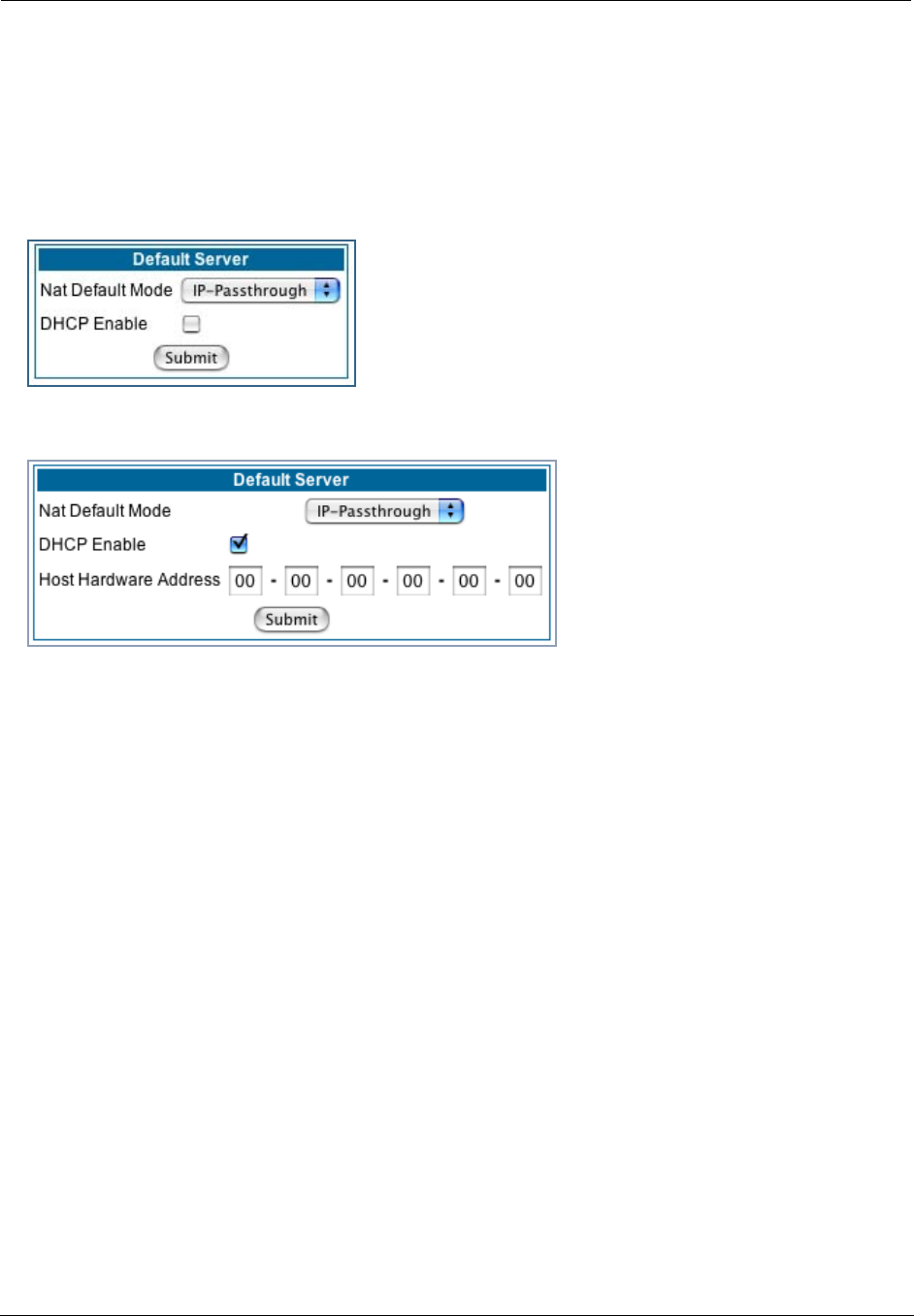
91
•DHCP address serving can automatically serve the WAN IP address to a LAN computer.
When DHCP is used for addressing the designated passthrough PC, the acquired or configured WAN
address is passed to DHCP, which will dynamically configure a single-servable-address subnet, and
reserve the address for the configured MAC address. This dynamic subnet configuration is based on the
local and remote WAN address and subnet mask. If the WAN interface does not have a suitable subnet
mask that is usable, for example when using PPP or PPPoE, the DHCP subnet configuration will default
to a class C subnet mask.
•If you want to manually assign the WAN address to a LAN PC, do not check the DHCP Enable checkbox.
•If you check the DHCP Enable checkbox, the screen expands.
The Host Hardware Address field displays. Here you enter the MAC address of the designated IP-
Passthrough computer.
•If this MAC address is not all zeroes, then it will use DHCP to set the LAN host's address to the (config-
ured or acquired) WAN IP address.
The MAC address must be six colon-delimited or dash-delimited sets of hex digits ('0' – 'FF').
•If you leave the MAC address as zeros then the first DHCP client will be assigned the WAN address.
Once configured, the passthrough host's DHCP leases will be shortened to two minutes. This allows for
timely updates of the host's IP address, which will be a private IP address before the WAN connection is
established. After the WAN connection is established and has an address, the passthrough host can renew
its DHCP address binding to acquire the WAN IP address.
A restriction. Since both the Gateway and the passthrough host will use the same IP address, new ses-
sions that conflict with existing sessions will be rejected by the Gateway. For example, suppose you are a
teleworker using an IPSec tunnel from the Gateway and from the passthrough host. Both tunnels go to the
same remote endpoint, such as the VPN access concentrator at your employer’s office. In this case, the
first one to start the IPSec traffic will be allowed; the second one – since, from the WAN, it's indistinguish-
able – will fail.
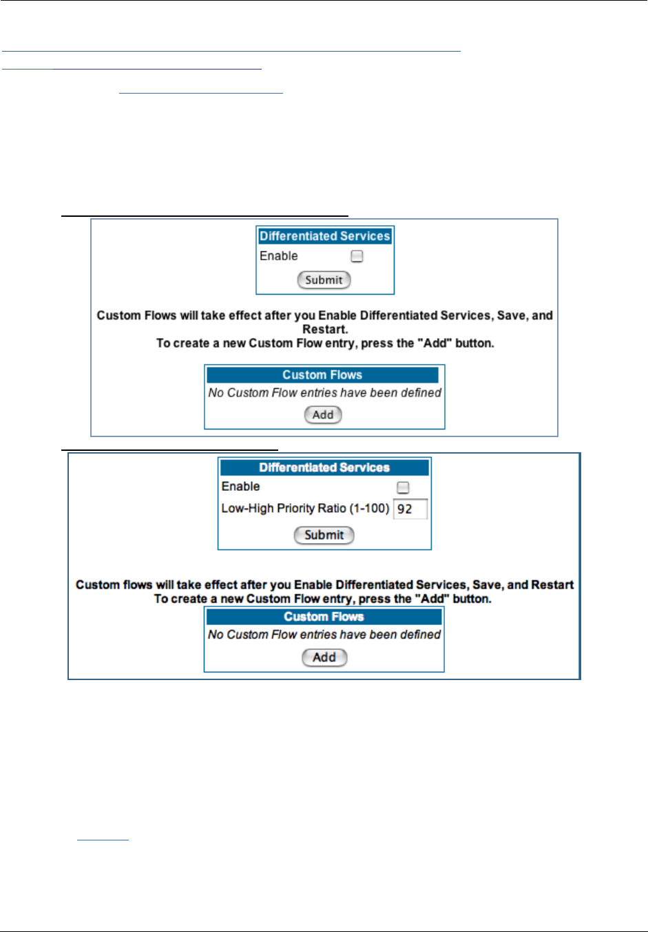
Administrator’s Handbook
92
Link: Differentiated Services
When you click the Differentiated Services link, the Differentiated Services configuration screen
appears.
Differentiated Services (Diffserv) allow your Gateway to make Quality of Service (QoS) decisions about
what path Internet traffic, such as Voice over IP (VoIP), should travel across your network. For example, you
may want streaming video conferencing to use high quality, but more restrictive, connections, or, you might
want e-mail to use less restrictive, but less reliable, connections.
VDSL and Bonded ADSL models display this screen:
Most other models display this screen:
•To enable Differentiated Services, check the Enable checkbox.
•(Not displayed on VDSL and Bonded ADSL models) Enter a value from 60 to 100 (percent) in the Low-
High Priority Ratio field. The default is 92.
Differentiated Services uses the low-to-high priority queue ratio to regulate traffic flow. For example, to
provide the least possible latency and highest possible throughput for high priority traffic, you could set
the ratio to 100(%). This would cause the gateway to forward low priority data only after the high priority
queue is completely empty. In practice, you should set it to something less than 100%, since the low pri-
ority traffic might have to wait too long to be passed, and consequently be subject to time-outs.
Click the Submit button.
You can then define Custom Flows. If your applications do not provide Quality of Service (QoS) control, Cus-
tom Flows allows you to define streams for some protocols, port ranges, and between specific end point
addresses.
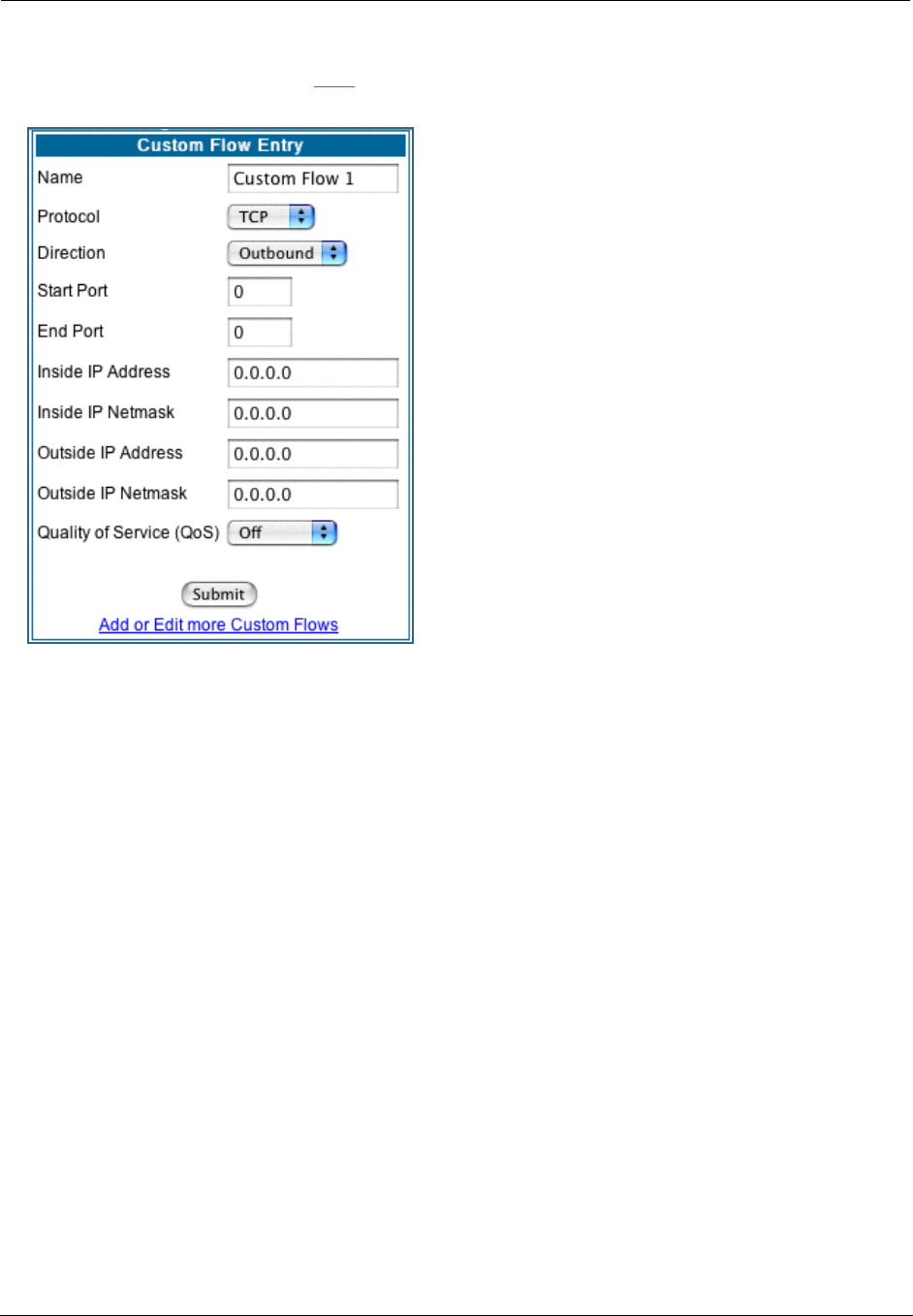
93
•To define a custom flow, click the Add button.
The Custom Flow Entry screen appears.
• Name – Enter a name in this field to label the flow.
• Protocol – Select the protocol from the pull-down
menu: TCP (default), UDP, ICMP, or Other. “Other” is
appropriate for setting up flows on protocols with non-
standard port definitions. IPSEC and PPTP are common
examples.
• Numerical Protocol – If you select “Other” protocol,
this field appears for you to provide its actual protocol
number, with a range of 0 – 255.
• Direction – Choose Outbound (default), Inbound, or
Both from the pull-down menu.
• Start Port – For TCP or UDP protocols, you can option-
ally specify a range of ports. Enter the starting port here.
• End Port – Enter the ending port here.
• Inside IP Address/Netmask – For outbound flows,
specify an IP address/netmask on your LAN. For inbound
flows, this setting is ignored. This setting marks packets
from this LAN IP host/network based on the address and
netmask information. For outbound flows, the Inside IP
Address/Netmask is the source address. If you enter a
zero IP address (0.0.0.0), the IP address/netmask fields
will be ignored.
• Outside IP Address/Netmask – If you want traffic destined for and originating from a certain WAN IP
address to be controlled, enter the IP address and subnet mask here. If you leave the default all-zeroes,
the outside address check is ignored.
For outbound flows, the outside address is the destination IP address for traffic; for inbound packets,
the outside address is the source IP address.
Note:
When setting the Inside/Outside IP Address/Netmask settings, note that a netmask value can be used
to configure for a network rather than a single IP address.

Administrator’s Handbook
94
• Quality of Service (QoS) – This is the Quality of Service setting for the flow, based on the TOS bit
information. Select Expedite, Assure, or Off (default) from the pull-down menu. The following table out-
lines the TOS bit settings and behavior:
QoS Setting TOS Bit Value Behavior
Off TOS=000 This custom flow is disabled. You can activate it by selecting one
of the two settings below. This setting allows you to pre-define
flows without actually activating them.
Assure TOS=001 Use normal queuing and throughput rules, but do not drop pack-
ets if possible. Appropriate for applications with no guaranteed
delivery mechanism.
Expedite TOS=101 Use minimum delay. Appropriate for VoIP and video applications.
Network Control TOS=111 Use highest possible priority.
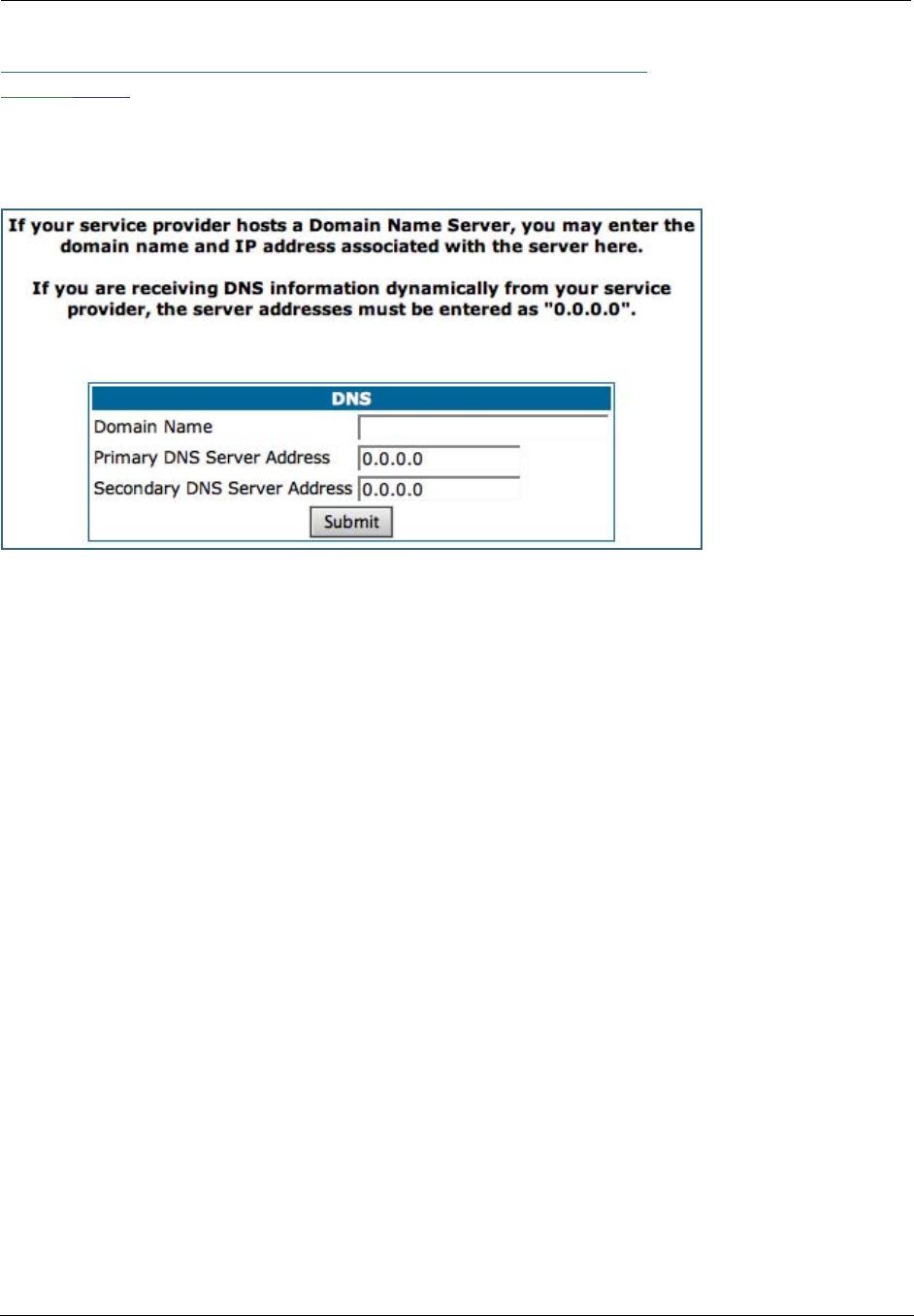
95
Link: DNS
Your Service Provider may maintain a Domain Name server. If you have the information for the DNS serv-
ers, enter it on the DNS page. If your Gateway is configured to use DHCP to obtain its WAN IP address, the
DNS information is automatically obtained from that same DHCP Server.
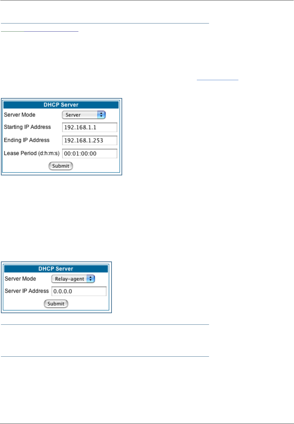
Administrator’s Handbook
96
Link: DHCP Server
Your Gateway can provide network configuration information to computers on your LAN, using the Dynamic
Host Configuration Protocol (DHCP).
If you already have a DHCP server on your LAN, you should turn this service off.
If you want the Gateway to provide this service, select Server from the Server Mode pull-down menu,
then configure the range of IP addresses that you would like the Gateway to hand out to your computers.
You can also specify the length of time the computers can use the configuration information; DHCP calls
this period the lease time.
Your Service Provider may, for certain services, want to provide configuration from its DHCP servers to the
computers on your LANs. In this case, the Gateway will relay the DHCP requests from your computers to a
DHCP server in the Service Provider's network.
Select Relay-agent and enter the IP address of the Service Provider's DHCP server in the Server Address
field. This address is furnished by the Service Provider.
☛ NOTE:
The relay-agent option only works when NAT is off and the Gateway is in router mode.
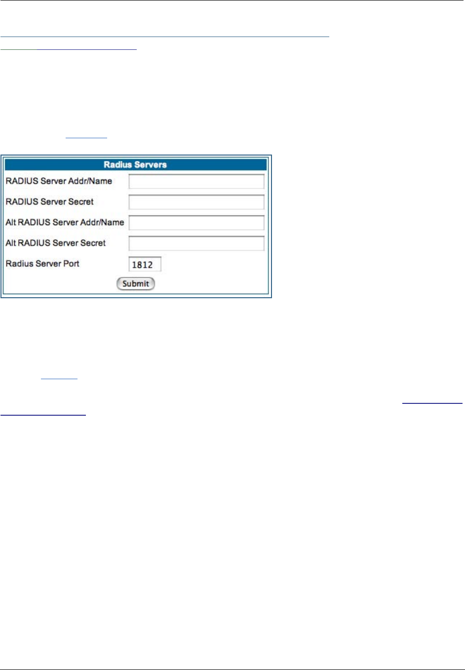
97
Link: RADIUS Server
RADIUS servers allow external authentication of users by means of a remote authentication database. The
remote authentication database is maintained by a Remote Authentication Dial-In User Service (RADIUS)
server. In conjunction with Wireless User Authentication, you can use a RADIUS server database to authen-
ticate users seeking access to the wireless services, as well as the authorized user list maintained locally
within the Gateway.
If you click the RADIUS link, the RADIUS Servers screen appears.
•RADIUS Server Addr/Name: The default RADIUS server name or IP address that you want to use.
•RADIUS Server Secret: The RADIUS secret key used by this server. The shared secret should have the
same characteristics as a normal password.
•RADIUS Server Port: The port on which the RADIUS server is listening, typically, the default 1812.
Click the Submit button.
You can also configure alternate RADIUS servers from the Wireless Configuration pages. See “Use RADIUS
Server” on page 65 for more information.
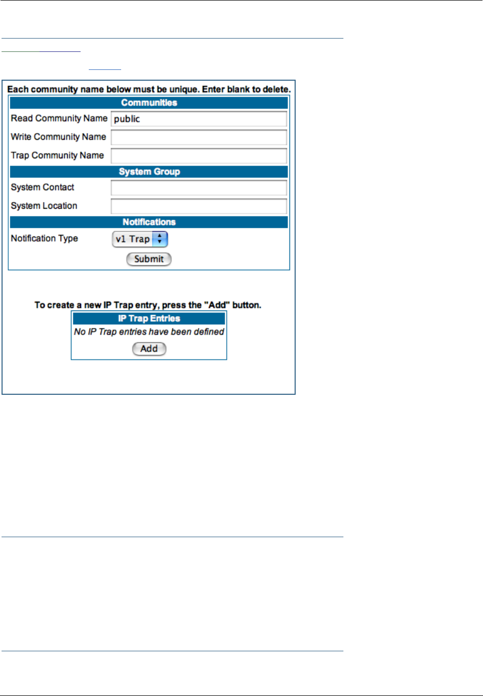
Administrator’s Handbook
98
Link: SNMP
When you click the SNMP link, the SNMP configuration page appears.
The Simple Network Management Protocol (SNMP) lets a network administrator monitor problems on a net-
work by retrieving settings on remote network devices. The network administrator typically runs an SNMP
management station program on a local host to obtain information from an SNMP agent. In this case, the
Motorola Netopia® Gateway is an SNMP agent. Your Gateway supports SNMP-V1, with the exception of
most sets (read-only and traps), and SNMP-V2. (For certain parts of the NPAV2TRAP.MIB – parameters under
resNatParams, resDslParams, resSecParams – set is supported.)
You enter SNMP configuration information on this page. Your network administrator furnishes the SNMP
parameters.
☛ WARNING:
SNMP presents you with a security issue. The community facility of SNMP behaves
somewhat like a password. The community “public” is a well-known community name.
It could be used to examine the configuration of your Gateway by your service provider
or an uninvited reviewer. The information can be read from the Gateway.
If you are strongly concerned about security, you may leave the “public” community
blank.
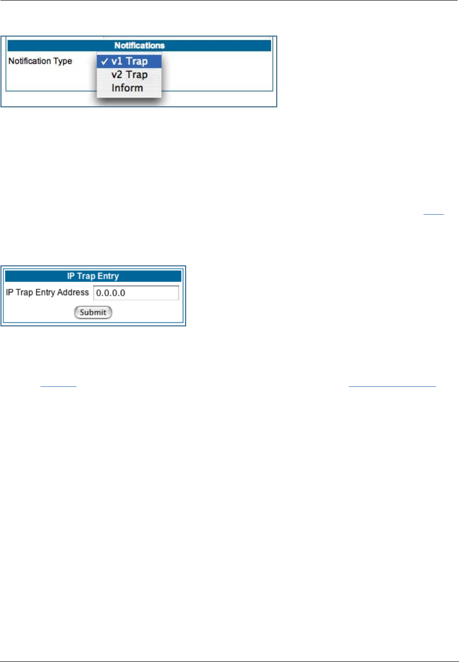
99
The Notification Type pull-down menu allows you to configure the type of SNMP notifications that will be
generated:
•v1 Trap – This selection will generate notifications containing an SNMPv1 Trap Protocol Data Unit (PDU)
•v2 Trap – This selection will generate notifications containing an SNMPv2 Trap PDU
•Inform – This selection will generate notifications containing an SNMPv2 InformRequest PDU.
To send SNMP traps, you must add IP addresses for each trap receiver you want to have. Click the Add
button.
The IP Trap Entry screen appears.
Enter an IP Trap Entry IP address. This is the destination for SNMP trap messages, the IP address of the
host acting as an SNMP console.
Click the Submit button. Click the Alert icon, and in the resulting page, click the Save and Restart link.

Administrator’s Handbook
100
Link: IGMP (Internet Group Management Protocol)
Multicasting is a method for transmitting large amounts of information to many, but not all, computers
over an internet. One common use is to distribute real time voice, video, and data services to the set of
computers which have joined a distributed conference. Other uses include updating the address books of
mobile computer users in the field, or sending out company newsletters to a distribution list.
Since a router should not be used as a passive forwarding device, Motorola Netopia® Gateways use a pro-
tocol for forwarding multicasting: Internet Group Management Protocol (IGMP).
Motorola Netopia® Gateways support IGMP Version 1, Version 2, or, beginning with Motorola Netopia®
Firmware Version 7.7, Version 3.
See the “Advanced” option in “LAN” on page 49 for more information.
IGMP “Snooping” is a feature of Ethernet layer 2 switches that “listens in” on the IGMP conversation
between computers and multicast routers. Through this process, it builds a database of where the multi-
cast routers reside by noting IGMP general queries used in the querier selection process and by listening to
other router protocols.
From the host point of view, the snooping function listens at a port level for an IGMP report. The switch
then processes the IGMP report and starts forwarding the relevant multicast stream onto the host's port.
When the switch receives an IGMP leave message, it processes the leave message, and if appropriate
stops the multicast stream to that particular port. Basically, customer IGMP messages although processed
by the switch are also sent to the multicast routers.
In order for IGMP snooping to function with IGMP Version 3, it must always track the full source filter state
of each host on each group, as was previously done with Version 2 only when Fast Leave support was
enabled.
IGMP Version 3 supports:
IGMP Source Filtering: the ability for group memberships to incorporate source address filtering. This allows
“Source-Specific Multicast” (SSM). By adding source filtering, a Gateway that proxies IGMP can more selec-
tively join the specific multicast group for which there are interested LAN multicast receivers.
These features require no user configuration on the Gateway.
To configure IGMP options available in Motorola Netopia® Gateways, click the IGMP link.
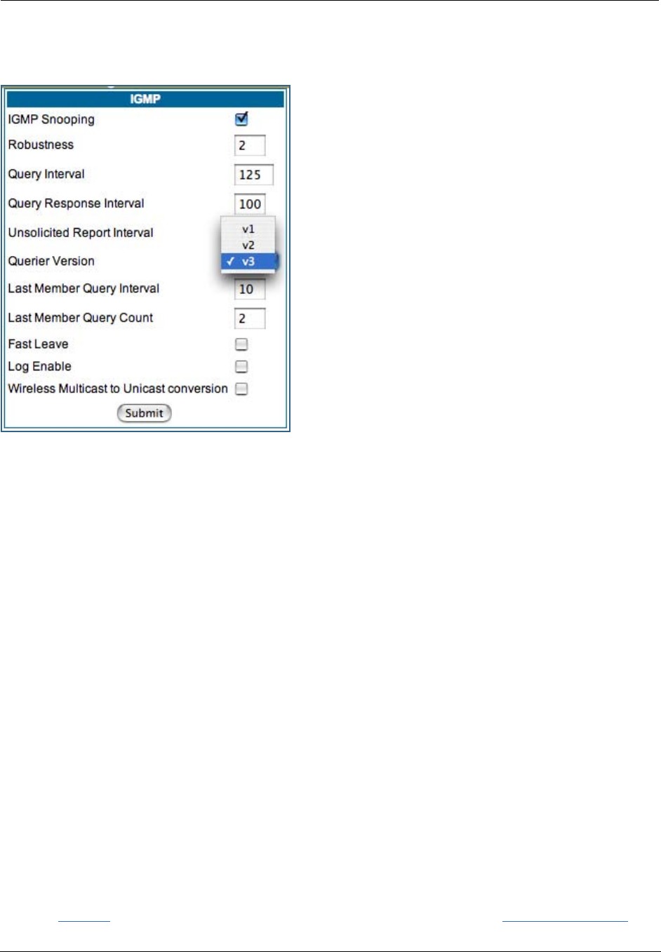
101
The IGMP page appears.
You can set the following options:
•IGMP Snooping – checking this checkbox enables the
Motorola Netopia® Gateway to “listen in” to IGMP traffic.
The Gateway discovers multicast group membership for
the purpose of restricting multicast transmissions to only
those ports which have requested them. This helps to
reduce overall network traffic from streaming media and
other bandwidth-intensive IP multicast applications.
•Robustness – a way of indicating how sensitive to lost
packets the network is. IGMP can recover from robustness
minus 1 lost IGMP packet. The default value is 2.
•Query Interval– the amount of time in seconds between
IGMP General Query messages sent by the querier gate-
way. The default query interval is 125 seconds.
•Query Response Interval – the maximum amount of
time in tenths of a second that the IGMP router waits to
receive a response to a General Query message. The
default query response interval is 10 seconds and must
be less than the query interval.
•Unsolicited Report Interval – the amount of time in
seconds between repetitions of a particular computer’s initial report of membership in a group. The
default unsolicited report interval is 10 seconds.
•Querier Version – Select a version of the IGMP Querier from the pull-down menu: v1, v2, or v3. The
default v3 allows for backward compatibility mode with the earlier versions, and should not need to be
changed. However, for administrative purposes you may select either v1 or v2.
•Last Member Query Interval – the amount of time in tenths of a second that the IGMP gateway waits
to receive a response to a Group-Specific Query message. The last member query interval is also the
amount of time in seconds between successive Group-Specific Query messages. The default last mem-
ber query interval is 1 second (10 deci-seconds).
•Last Member Query Count – the number of Group-Specific Query messages sent before the gateway
assumes that there are no members of the host group being queried on this interface. The default last
member query count is 2.
•Fast Leave – Checking this checkbox enables a non-standard expedited leave mechanism. The querier
keeps track of which client is requesting which channel by IP address. When a leave message is
received, the querier can check its internal table to see if there are any more clients on this group. If
there are none, it immediately sends an IGMP leave message to the upstream querier. By default, Fast
Leave is set to Off.
•Log Enable – If you check this checkbox, all IGMP messages on both the LAN and the WAN will be
logged.
•Wireless Multicast to Unicast conversion – This checkbox only appears if IGMP Snooping is
enabled. If you check this checkbox, the Gateway replaces the multicast MAC-address with the physical
MAC-address of the wireless client. If there is more than one wireless client interested in the same mul-
ticast group, the router will revert to multicasting the stream immediately. When one or more wireless
clients leave a group, and the router determines that only a single wireless client is interested in the
stream, it will once again unicast the stream.
Click the Submit button. Click the Alert icon, and in the resulting page, click the Save and Restart link.

Administrator’s Handbook
102
Link: UPnP
Universal Plug and Play (UPnP™) is a set of protocols that allows a PC to automatically discover other UPnP
devices (anything from an internet gateway device to a light switch), retrieve an XML description of the
device and its services, control the device, and subscribe to real-time event notification.
By default, UPnP is enabled on the Motorola Netopia® Gateway.
For Windows XP users, the automatic discovery feature places an icon representing
the Motorola Netopia® Gateway automatically in the “My Network Places” folder.
Double-clicking this icon opens the Gateway’s web UI.
PCs using UPnP can retrieve the Gateway’s WAN IP address, and automatically cre-
ate NAT port maps. This means that applications that support UPnP, and are used
with a UPnP-enabled Motorola Netopia® Gateway, will not need application layer
gateway support on the Motorola Netopia® Gateway to work through NAT.
You can disable UPnP, if you are not using any UPnP devices or applications.
•Uncheck the UPnP Enabled checkbox, and click the Submit button.
•The Alert icon will appear in the upper right corner of the web page. Click the Alert icon, and when
prompted, click the Save and Restart link.
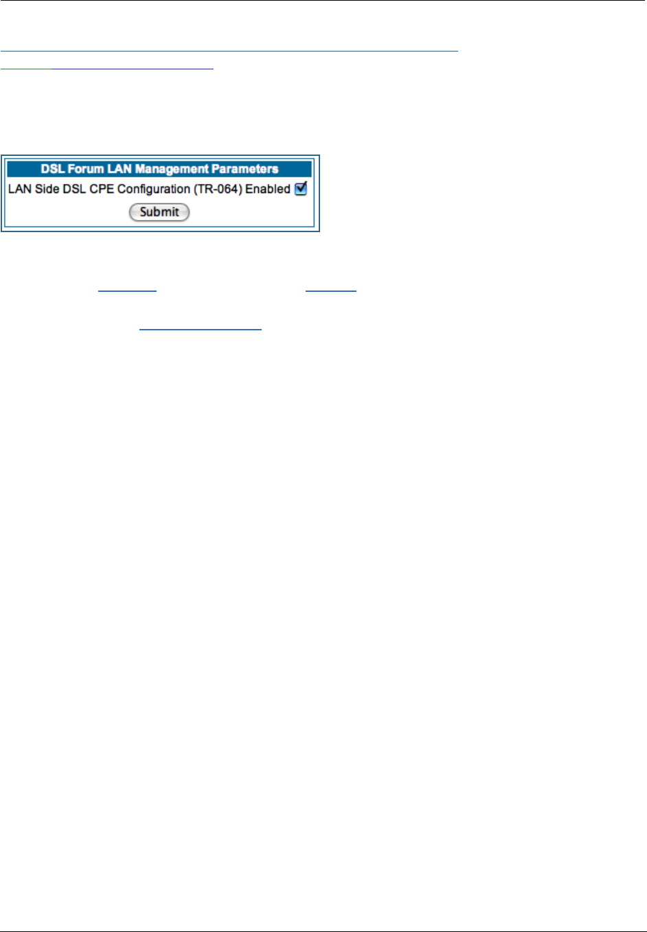
103
Link: LAN Management
TR-064 is a LAN-side DSL Gateway configuration specification. It is an extension of UPnP. It defines more
services to locally manage the Motorola Netopia® Gateway. While UPnP allows open access to configure
the Gateway's features, TR-064 requires a password to execute any command that changes the Gateway's
configuration.
TR-064 is enabled by default. To disable it:
•Uncheck the Enabled checkbox, and click the Submit button.
•The Alert icon will appear in the upper right corner of the web page. Click the Alert icon, and when
prompted, click the Save and Restart link.

Administrator’s Handbook
104
Link: Ethernet Bridge
The Motorola Netopia® Gateway can be used as a bridge, rather than a router. A bridge is a device that
joins two networks. As an Internet access device, a bridge connects the home computer directly to the ser-
vice provider’s network equipment with no intervening routing functionality, such as Network Address Trans-
lation. Your home computer becomes just another address on the service provider’s network. In a DSL
connection, the bridge serves simply to convey the digital data information back and forth over your tele-
phone lines in a form that keeps it separate from your voice telephone signals.
If your service provider’s network is set up to provide your Internet connectivity via bridge mode, you can set
your Motorola Netopia® Gateway to be compatible.
Bridges let you join two networks, so that they appear to be part of the same physical network. As a bridge
for protocols other than TCP/IP, your Gateway keeps track of as many as 512 MAC (Media Access Control)
addresses, each of which uniquely identifies an individual host on a network. Your Gateway uses this bridg-
ing table to identify which hosts are accessible through which of its network interfaces. The bridging table
contains the MAC address of each packet it sees, along with the interface over which it received the
packet. Over time, the Gateway learns which hosts are available through its WAN port and/or its LAN port.
When configured in Bridge Mode, the Motorola Netopia® will act as a pass-through device and allow the
workstations on your LAN to have public addresses directly on the internet.
☛ NOTE:
In this mode the Motorola Netopia® is providing NO firewall protection as is afforded by NAT.
Also, only the workstations that have a public address can access the internet. This can be
useful if you have multiple static public IPs on the LAN.
Bridging per WAN is supported in conjunction with VLANs – individual WANs can be bridged to the LAN only
if the WANs are part of a VLAN. (See “VLAN” on page 107 for more information.) The capability to bridge
individual VLANs is supported only if the underlying encapsulation is RFC1483-Bridged (ether-llc).
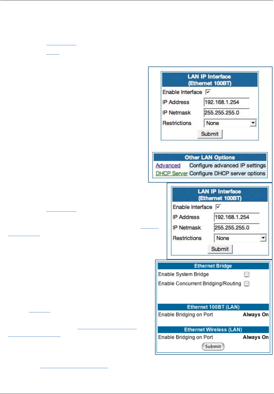
105
Configuring for Bridge Mode
1. Browse into the Motorola Netopia® Gateway’s web interface.
2. Click on the Configure button in the upper Menu bar.
3. Click on the LAN link.
The LAN page appears.
4. In the box titled LAN IP Interface (Ethernet
100BT):
Make note of the Ethernet IP Address and subnet mask.
You can use this address to access the router in the future.
5. Click on the Advanced link in the left-hand links
toolbar.
6. Under the heading of Services, click on the Ether-
net Bridge link.
The Ethernet Bridge page appears.
The appearance of this page varies, depending on your
Gateway’s interfaces.
7. If available:
a. Check the Enable Bridging on Port selection. (This
may be Always On.)
b. Click Submit.
8. If you want the Gateway to do both bridging
and routing, check the Enable Concurrent
Bridging/Routing checkbox.
When this mode is enabled, the Gateway will appear to
be a router, but also bridge traffic from the LAN if it has
a valid LAN-side address.
9. Check the Enable System Bridge checkbox.
The window shrinks.
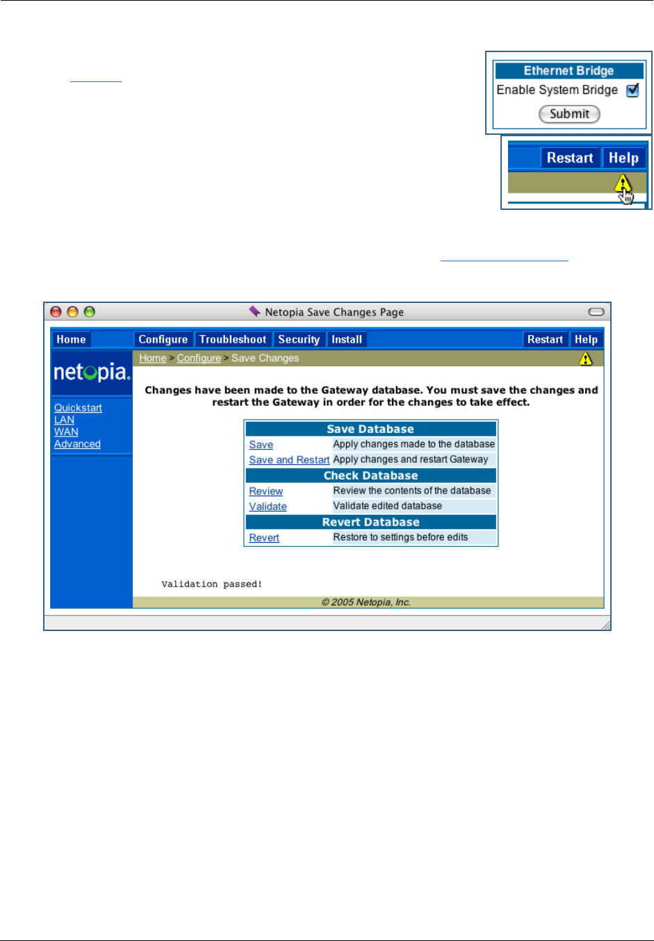
Administrator’s Handbook
106
b. Click Submit.
At this point you should be ready to do the final save on the configuration
changes you have made.
The yellow Alert symbol will appear beneath the Help button on the right-hand
end of the menu bar.
10. Click on the Alert symbol and you will see whether your changes
have been validated.
11. If you are satisfied with the changes you have made, click Save and Restart in the Save
Database box to Apply changes and restart Gateway.
You have now configured your Motorola Netopia® Gateway for bridging, and it will bridge all traffic across
the WAN. You will need to make configurations to your machines on your LAN. These settings must be made
in accordance with your ISP. If you ever need to get back into the Motorola Netopia® Gateway again for
management reasons, you will need to manually configure your machine to be in the same subnet as the
Ethernet inter face of the Motorola Netopia®, since DHCP server is not operational in bridge mode.
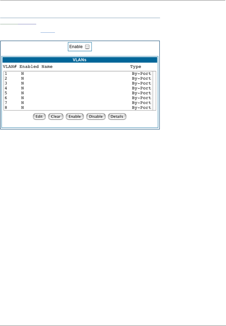
107
Link: VLAN
When you click the VLAN link the VLANs page appears.
Overview
A Virtual Local Area Network (VLAN) is a network of computers or other devices that behave as if they are
connected to the same wire even though they may be physically located on different segments of a LAN.
You set up VLANs by configuring the Gateway software rather than hardware. This makes VLANs very flexi-
ble. VLANs behave like separate and independent networks.
Beginning with Version 7.7.4, VLANs are now strictly layer 2 entities. They can be thought of as virtual
Ethernet switches, into which can be added: Ethernet ports, router IP interfaces, ATM PVC/VCC interfaces,
SSIDs, and any other physical port such as USB, HPNA, or MOCA. This allows great flexibility on how the
components of a system are connected to each other.
VLANs are part of Motorola’s VGx Virtual Gateway technology which allows individual port-based VLANs to
be treated as separate and distinct “channels.” When data is passed to a Motorola Netopia VGx-enabled
broadband gateway, specific policies, routing, and prioritization parameters can be applied to each individ-
ual service, delivering that service to the appropriate peripheral device with the required level of quality of
service (QoS). In effect, a single Motorola gateway acts as separate virtual gateways for each distinct ser-
vice being delivered.
Motorola’s VGx technology maps multiple local VLANs to one or more specific permanent virtual circuits
(PVCs) for DSL, or wide area network VLANs for a fiber network. VGx provides service segmentation and
QoS controls, service management, and supports delivery of triple play applications: voice for IP Telephony,
video for IPTV, and data.
Your Gateway supports the following:
•Port-based VLANs - these can be used when no trunking is required
•Global VLANs - these are used when trunking is required on any port member of the VLAN
- Supports 802.1q and 802.1p; both are configurable
•Routed VLANs

Administrator’s Handbook
108
- WAN-side VLAN with Multiple WAN IPoE interface support and IP interface-to-VLAN binding
- LAN-side VLAN with IP interface-to-VLAN binding
- Inter-VLAN routing
•Bridged VLANs - these VLANs are used to bridge traffic from LAN to WAN
•Prioritization per VLAN and per port
Ethernet Switching/Policy Setup
Before you configure any VLANs, the unconfigured Gateway is set up as a router composed of a LAN switch,
a WAN switch, and a router in the middle, with LAN and WAN IP interfaces connected to their respective
switches. These bindings between Ethernet switch ports, IP LAN interface, IP WAN interface and WAN phys-
ical ports are automatically created.
When you configure any VLANs, the default bindings are no longer valid, and the system requires explicit
binding between IP interfaces and layer 2 inter faces. Each VLAN can be thought of as a layer 2 switch, and
enabling each port or interface in a VLAN is analogous to plugging it in to the layer 2 switch.
Thereafter, in order for devices to communicate on layer 2, they must be associated in the same VLAN. For
devices to communicate at layer 3, the devices must be either on the same VLAN, or on VLANs that have an
Inter-VLAN routing group enabled in common.
When configuring VLANs you must define how traffic needs to be forwarded:
•If traffic needs to be bridged between LAN and WAN you can create a single VLAN that encompasses the
WAN port and LAN ports.
•If traffic needs to be routed then you must define four elements:
• LAN-side VLANs
• WAN-side VLANs
• Associate IP Interfaces to VLANs
• Inter-VLAN Routing Groups: configuration of routing between VLANs is done by association of a VLAN
to a Routing Group. Traffic will be routed between VLANs within a routing group. The LAN IP Ethernet
Interface can be bound to multiple LAN VLANs, but forwarding can be limited between an Ethernet LAN
port and a WAN VLAN if you properly configure Inter-VLAN groups.
Inter-VLAN groups are also used to block routing between WAN interfaces. If each WAN IP interface is
bound to its own VLAN and if you configure a different Inter-VLAN group for each WAN VLAN then no rout-
ing between WAN IP interfaces is possible.
•Example: to route between a VCC and all the LAN ports, which effectively is similar to the default config-
uration without any VLANs:
Create a VLAN named "VccWan" consisting of vcc1, ip-vcc1, routing-group 1
Create a VLAN named "Lan" consisting of eth0.1, eth0.2, eth0.3, eth0.4, ssid1, ssid2, ssid3, ssid4
(etc.), ip-eth-a, routing-group 1
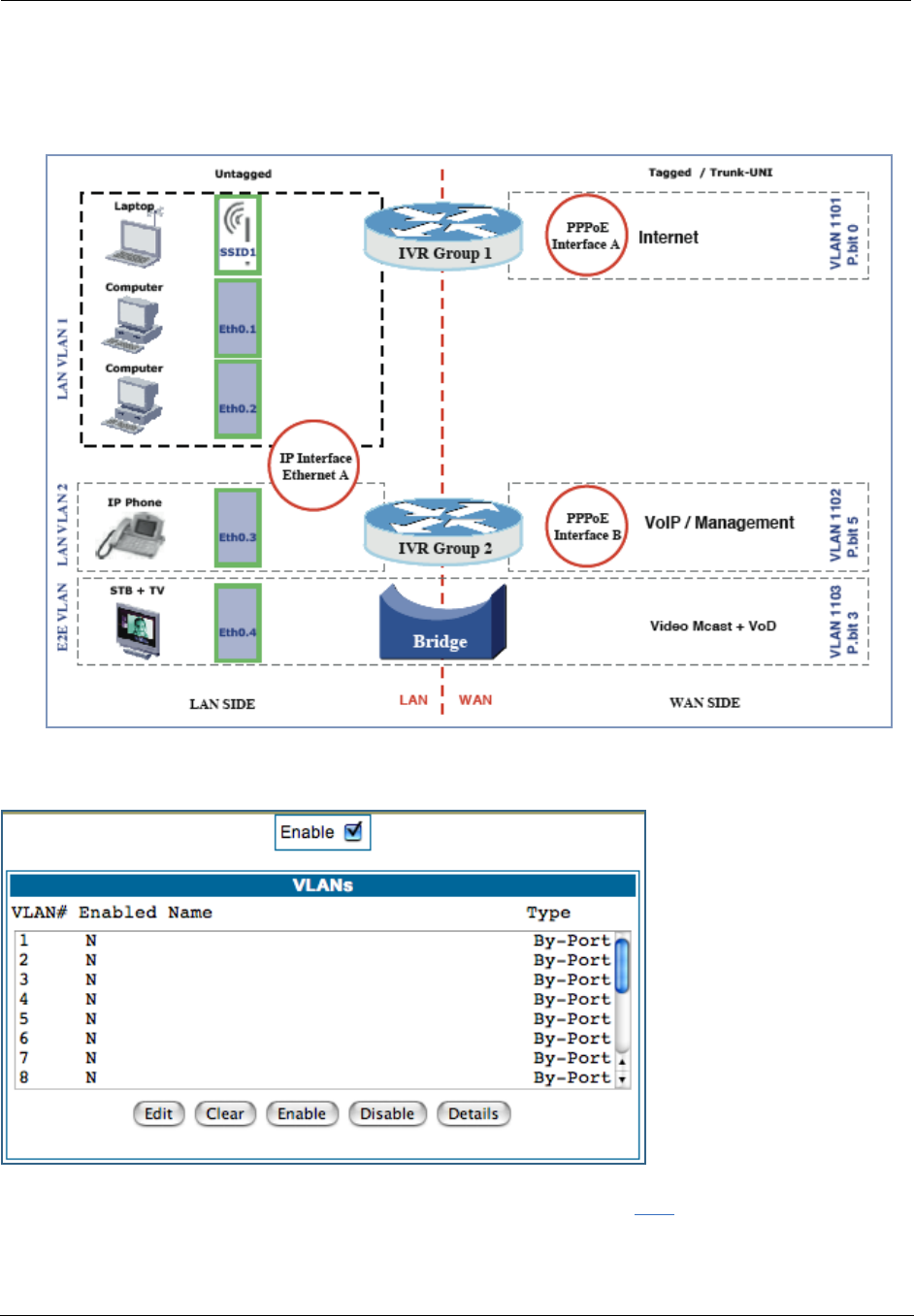
109
An example of multiple VLANs, using a Motorola Netopia® Gateway with VGx managed switch technology, is
shown below:
A VLAN Model Combining Bridging and Routing
To configure VLANs check the Enable checkbox.
To create a VLAN select a list item from the main VLAN page and click the Edit button.
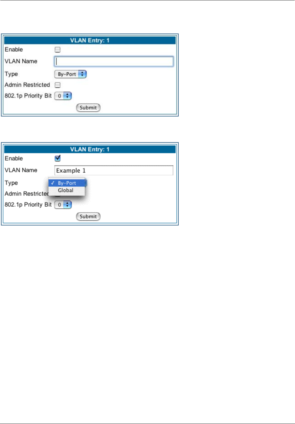
Administrator’s Handbook
110
The VLAN Entry page appears.
Check the Enable checkbox, and enter a descriptive name for the VLAN.
You can create up to 16 VLANs, and you can also restrict any VLAN, and the computers on it, from adminis-
tering the Gateway.
•VLAN Name – A descriptive name for the VLAN.
•Type – LAN or WAN Port(s) can be enabled on the VLAN. You can choose a type designation as follows:
By-Port: indicates that the VLAN is port-based. Traffic sent to this port will be treated as belonging to
the VLAN, and will not be forwarded to other ports that are not within a common VLAN segment.
Global indicates that the ports joining this VLAN are part of a global 802.1q Ethernet VLAN. This VLAN
includes ports on this Router and may include ports within other devices throughout the network. The
VID in this case may define the behavior of traffic between all devices on the network having ports that
are members of this VLAN segment.
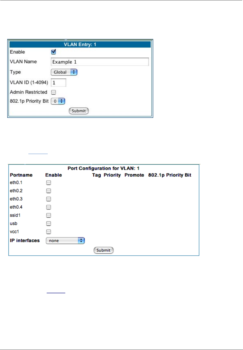
111
•VLAN ID – If you select Global as the VLAN Type, the VLAN ID field appears for you to enter a VID. This
must be a unique identifying number between 1 and 4094. (A VID of zero (0) is permitted on the Ether-
net WAN port only.)
•Admin Restricted – If you want to prevent administrative access to the Gateway from this VLAN, check
the checkbox.
•802.1p Priority Bit: If you set this from the pull-down menu to a value greater than 0, all packets of this
VLAN with unmarked priority bits (pbits) will be re-marked to this priority.
Click the Submit button.
The VLAN Port Configuration screen appears.
•Port interfaces available for this VLAN are listed in the left hand column.
•Displayed port interfaces vary depending on the kinds of physical ports on your Gateway, for example,
Ethernet, USB, and/or wireless.
Also, if you have multiple wireless SSIDs defined, these may be displayed as well (See Enable Multiple
Wireless IDs on page 59)
•For Motorola Netopia® VGx technology models, separate Ethernet switch ports are displayed and may
be configured.
To enable any of them on this VLAN, check the associated Enable checkbox(es).
Typically you will choose a physical port, such as an Ethernet port (example: eth0.1) or a wireless SSID
(example: ssid1).
•When you enable an interface, the Tag, Priority, and Promote checkboxes and an 802.1p Priority Bit
pull-down menu appear for that interface.
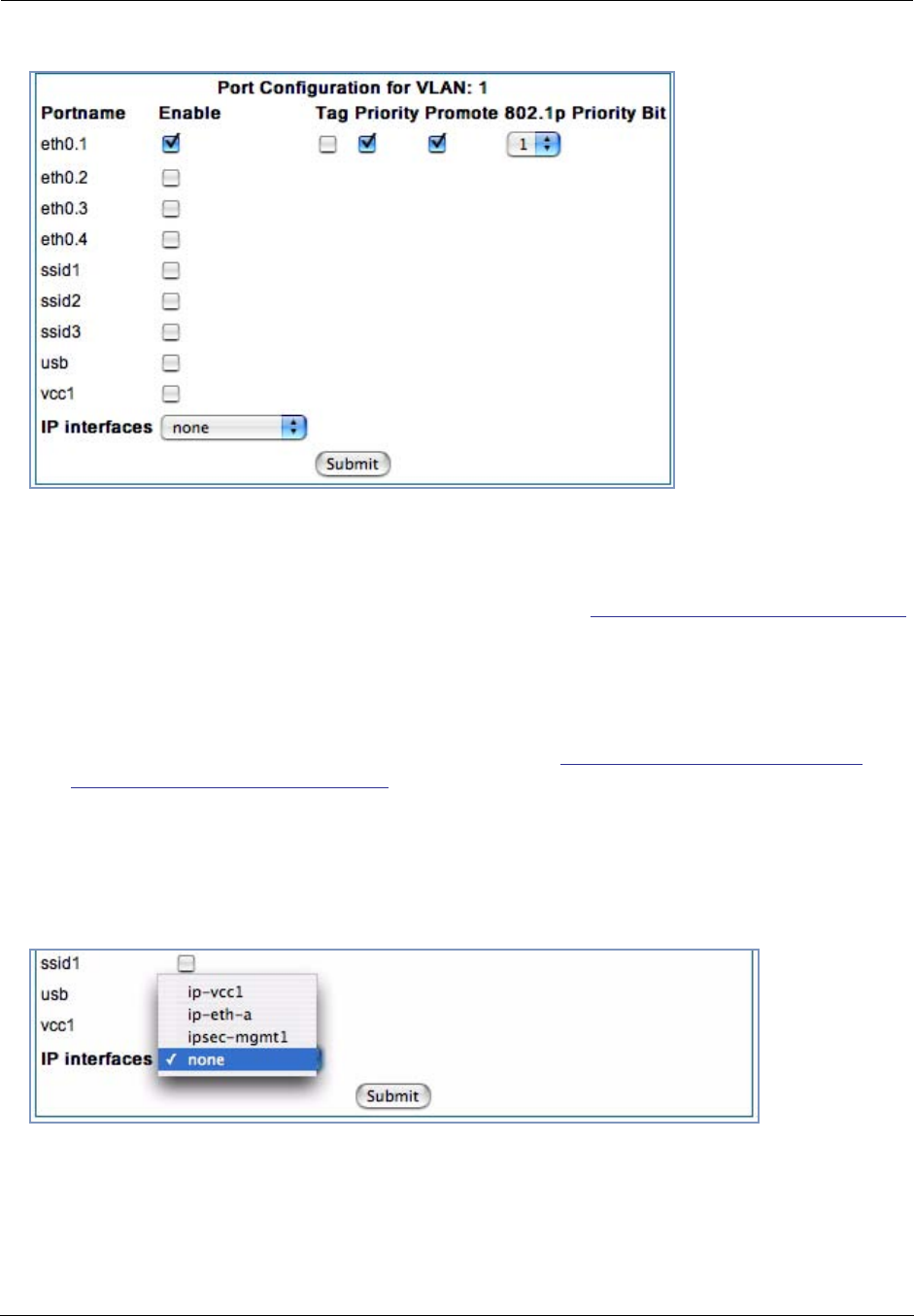
Administrator’s Handbook
112
Tag – Packets transmitted from this port through this VLAN must be tagged with the VLAN VID. Packets
received through this port destined for this VLAN must be tagged with the VLAN VID by the source. The
Tag option is only available on Global type ports.
Priority – Use any 802.1p priority bits in the VLAN header to prioritize packets within the Gateway’s
internal queues, according to DiffServ priority mapping rules. See “Differentiated Services” on page 92
for more information.
Promote – Write any 802.1p priority bits into the IP-TOS header bit field for received IP packets on this
port destined for this VLAN. Write any IP-TOS priority bits into the 802.1p priority bit field for tagged IP
packets transmitted from this port for this VLAN.
All mappings between Ethernet 802.1p and IP-TOS are made according to a pre-defined QoS mapping
policy. The pre-defined mapping can now be set in the CLI. See “Queue Configuration” on page 271. See
also “Differentiated Services” on page 92 for more information.
802.1p Priority Bit – If you set this field to a value greater than 0, all packets received on this port with
unmarked priority bits (pbits) will be re-marked to this priority. If the port 802.1p PBit is greater than 0,
the VLAN 802.1p PBit setting is ignored.
•Select an IP Interface for this VLAN if it is to be routed; otherwise leave the default. These selections
will vary depending on your IP interfaces. For example, if you have set up multiple VCCs, these will
appear in the list as ip-vcc1, ip-vcc2, and so forth.
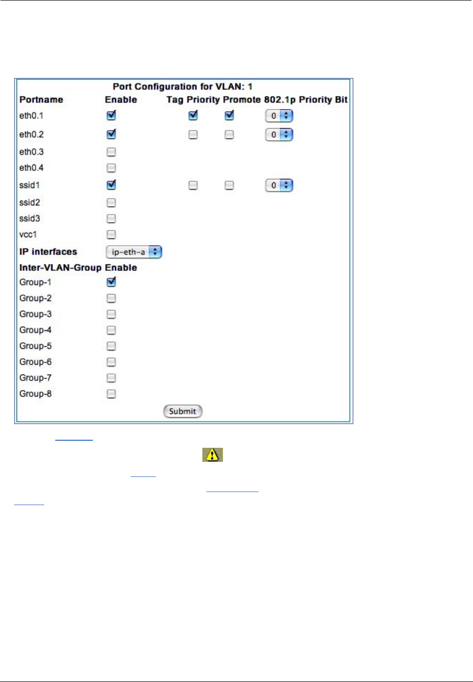
113
•When you select an IP interface, the screen expands to allow you to configure Inter-Vlan-Groups.
Inter-VLAN groups allow VLANs in the group to route traffic to the others; ungrouped VLANs cannot route
traffic to each other.
•Click the Submit button.
•When you are finished, click the Alert icon in the upper right-hand corner of the screen, and in the
resulting screen, click the Save link.
•If you want to create more VLANs, click the Advanced link (in the left-hand toolbar) and then the
VLAN link in the resulting page, and repeat the process.
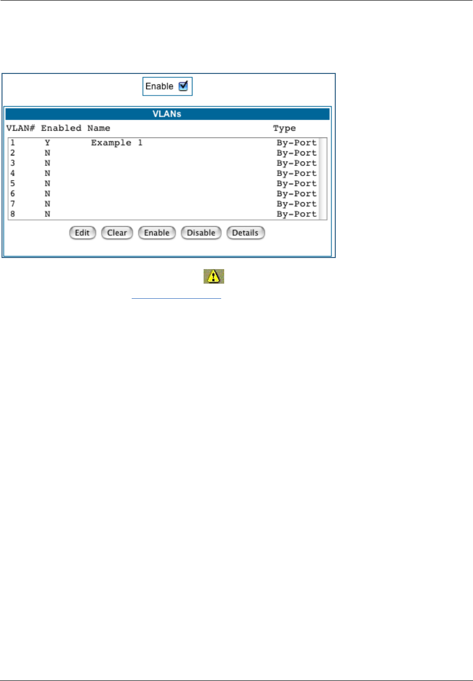
Administrator’s Handbook
114
You can Edit, Clear, Enable, or Disable your VLAN entries by returning to the VLANs page, and selecting
the appropriate entry from the displayed list.
•When you are finished, click the Alert icon in the upper right-hand corner of the screen, and in the
resulting screen, click the Save and Restart link.
To view the settings for each VLAN, select the desired VLAN from the list and click the Details button.
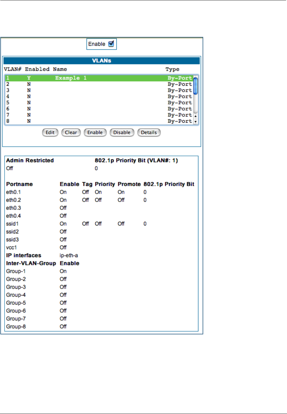
115
The screen expands to display the VLAN settings.
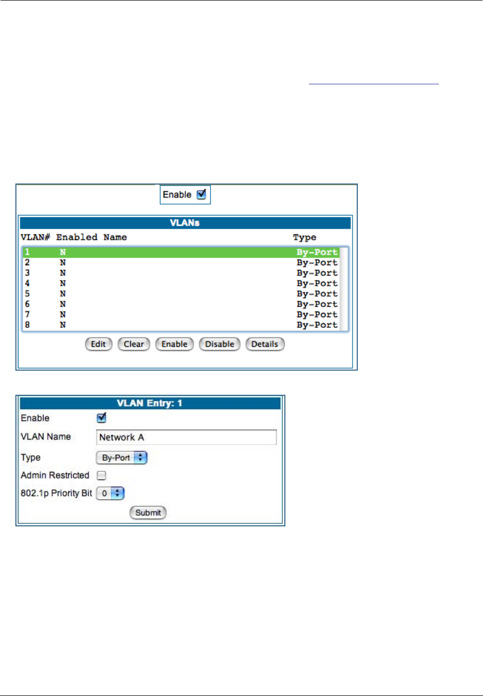
Administrator’s Handbook
116
Example
The following is a simple example of how you might configure some VLANs:
You want to configure a 3347NWG-VGx Gateway with two SSIDs (see “Multiple SSIDs” on page 59 for more
information) for two VLANs, allowing both access to the Internet. One SSID will be in the same VLAN as the
four ports of the Ethernet Switch, so that those two networks can communicate. The second VLAN will be
for the other SSID. The second VLAN will also be denied access to the 3347NWG-VGx web interface and tel-
net interface. This setup might be useful if you have a doctor’s office or a coffee shop, and you want to
keep your customers separated from the rest of the network.
1. In the VLANs page, check the Enable checkbox, select VLAN #1 in the VLANs list, and
click the Edit button.
2. Check the Enable checkbox, and in the VLAN Name box, enter the name you would like.
For example, call it Network A.
Since this VLAN will be for SSID1 and the Ethernet ports, leave Admin Restricted unchecked. This will
give this VLAN access to the Gateway.
3. Click the Submit button.
4. In the Port Configuration for VLAN:1 page, you add the Port Interfaces you want associ-
ated with the VLAN.
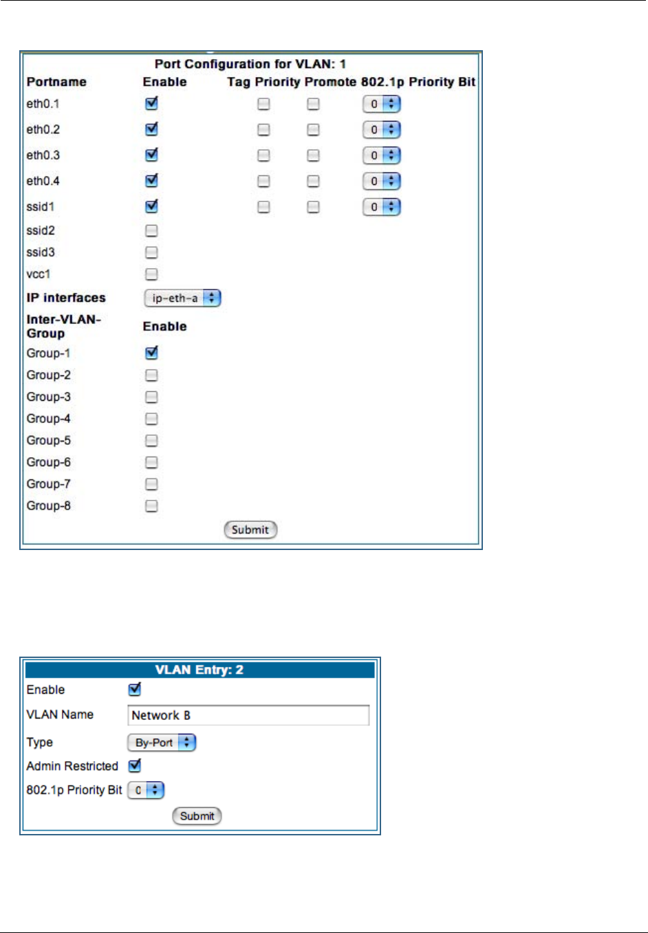
117
In this case, select all the physical Ethernet ports: eth0.1 through eth0.4, and wireless ssid1. Select
ip-eth-a, the IP interface for the group. This will be Inter-Vlan-Group #1. Check the Group-1 checkbox.
These ports will be able to communicate with each other.
5. Click the Submit button.
6. In the VLAN page, select VLAN #2 in the VLANs list, and click the Edit button.
The VLAN Name must be given another unique name. For example, call it Network B.
Since this is for the second SSID that we don’t want to be given access to the Gateway, check the
Admin Restricted checkbox.
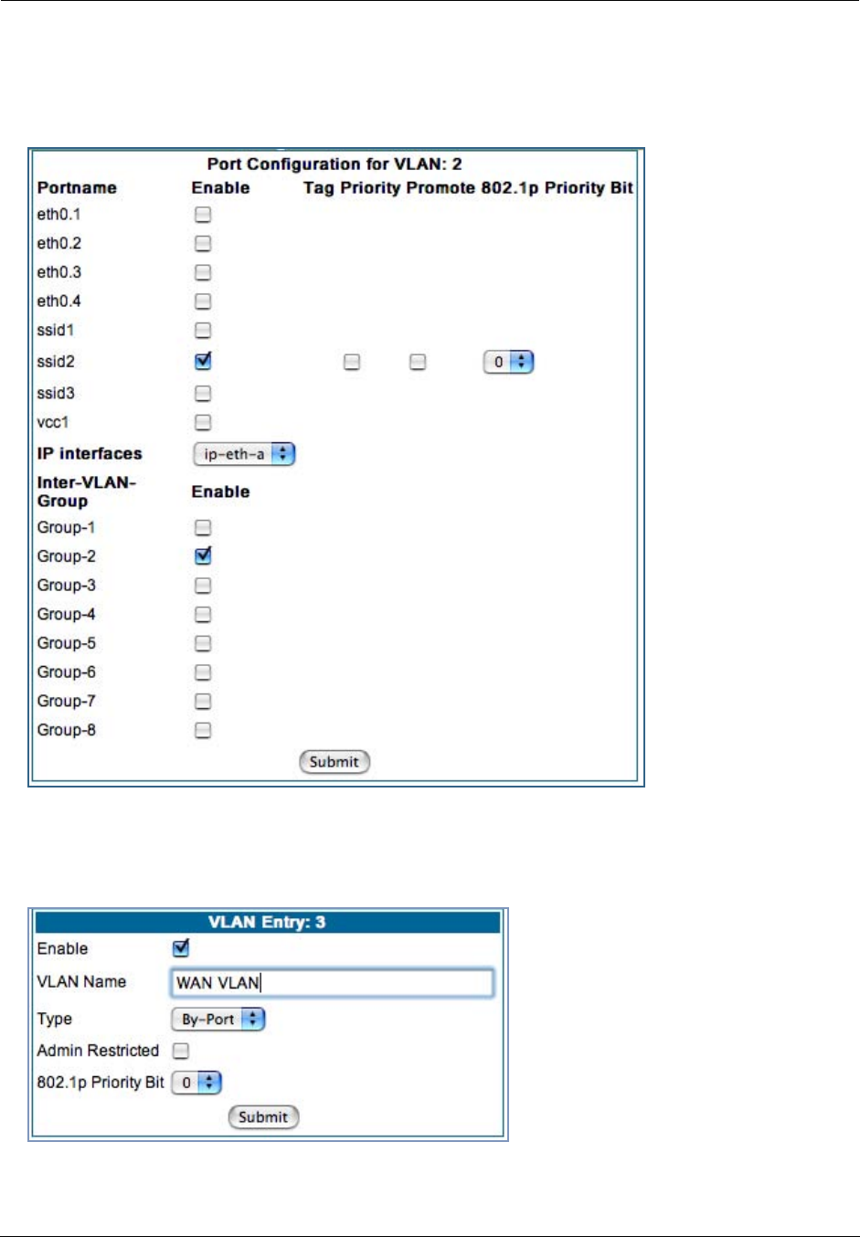
Administrator’s Handbook
118
7. Click the Submit button.
8. In the Port Configuration for VLAN: 2 page, you add the Port Interfaces you want asso-
ciated with the VLAN.
Select the ip-eth-a port interface and check the ssid2 port interface. Make this VLAN a member of
Inter-Vlan-Group Group-2.
9. Click the Submit button.
10. Next, create a VLAN to provide the Inter-Vlan-Groups access to the Internet (WAN).
For example, call it WAN VLAN.
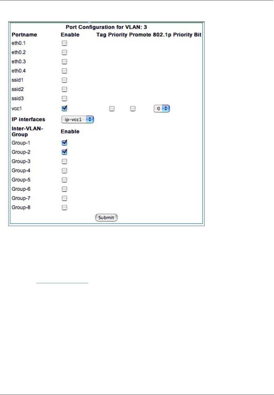
119
Check the vcc1 checkbox, select the ip-vcc1 IP interface, and check the Inter-Vlan-Group Group-1 and
Group-2 checkboxes. Members of Groups 1 and 2 will now be able to communicate with the Internet
(WAN), but not with each other.
11. Once you have finished with the configuration of the VLANs, click the Alert icon in the
upper right hand corner.
This will validate that the settings are legal for your network.
12. Click the Save and Restart link.
This will restart the Motorola Netopia® Gateway and retain the VLAN configuration.
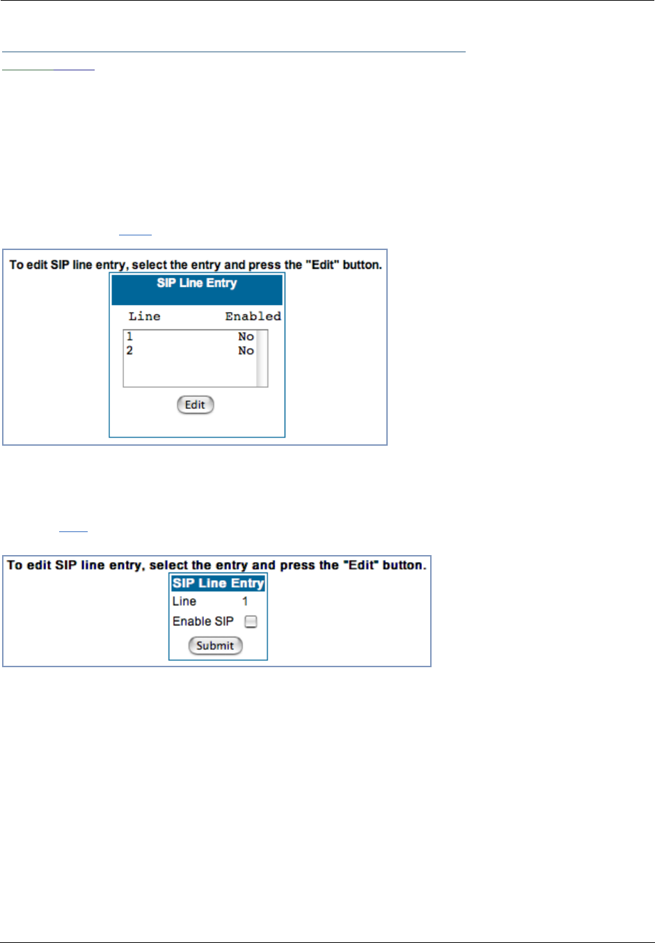
Administrator’s Handbook
120
Link: VoIP
(supported models only)
Voice-over-IP (VoIP) refers to the ability to make voice telephone calls over the Internet. This differs from tra-
ditional phone calls that use the Public Switched Telephone Network (PSTN). VoIP calls use an Internet pro-
tocol, Session Initiation Protocol (SIP), to transmit sound over a network or the Internet in the form of data
packets. Certain Motorola Netopia® Gateway models have two separate voice ports for connecting tele-
phone handsets. These models support VoIP. If your Gateway is a VoIP model, you can configure the VoIP
features.
When you click the VoIP link, the SIP Line Entry page appears.
To enable a VoIP line, select one of the lines from the SIP Line Entry menu that corresponds to the port on
the Gateway to which your phone is connected.
Click the Edit button. In the resulting screen, check the Enable SIP checkbox.
The screen expands to display the features that you can enable for that line.
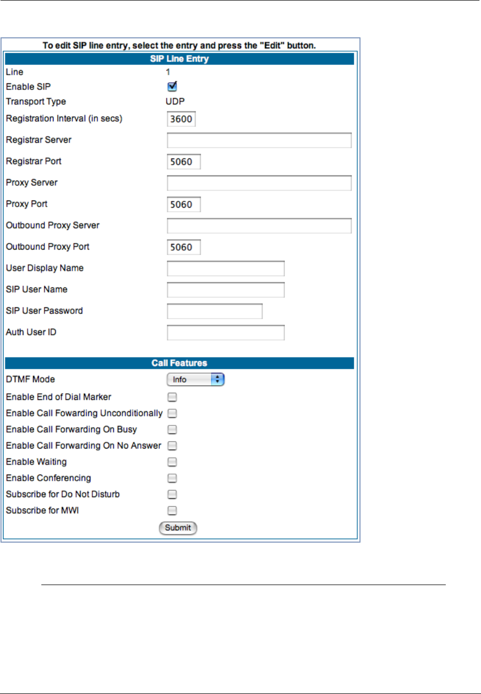
121
SIP Line Entry
Registration Interval
(in secs)
Length of time the VoIP registration will be valid before it will be
renewed. Default is 1 hour.
Registrar Server Registration Server name or IP address.
Registrar Port Registration Server port. Default is 5060.
Proxy Server Proxy server name or IP address.

Administrator’s Handbook
122
When you are finished entering the required information, click the Submit button.
To configure the second voice port, return to the SIP Line Entry screen by clicking the VoIP link in the
Breadcrumb Trail.
When you are finished, click the Alert icon in the upper right corner of the page, and in the resulting
page, click the Save and Restart link.
Proxy Port Proxy server port, if required. Default is 5060.
Outbound Proxy Server Outbound Proxy server name or IP address, if required.
Outbound Proxy Port Outbound Proxy server port, if required. Default is 5060.
User Display Name Name of this phone’s user to be displayed on the Home page.
Example: “Jacob Q. Smith”
SIP User Name Registration user ID. Example: “jqsmith”
SIP User Password Registration user password.
Auth User ID The authorization ID that authenticates the user to SIP for
the specified phone. Most SIP Servers expect this to be
the User Name itself but some may use Auth User ID.
Call Features Settings
DTMF Mode Choose the Dual Tone Multi-Frequency Mode:
• Inband: Sends the DTMF digits as a normal inband tone.
• RFC2833: Sends the DTMF digits as an event as part of the
RTP packet header information.
• Info: Sends the DTMF digits in the SIP INFO message.
Enable End of Dial Marker If you check this checkbox, the Gateway will generate an “end of
dial” (#) signal that indicates that the dialed number is complete.
Enable Call Fowarding
Unconditionally
If you check this checkbox, all calls will be forwarded to a speci-
fied number.
The Unconditional Call Fowarding Number field will appear for
you to enter the number, if enabled.
Enable Call Forwarding On
Busy
If you check this checkbox, calls will be forwarded to a specified
number if the line is busy.
The On Busy Call Fowarding Number field will appear for you
to enter the number, if enabled.
Enable Call Forwarding On
No Answer
If you check this checkbox, calls will be forwarded to a specified
number if there is no answer.
The On No Answer Call Fowarding Number field will appear for
you to enter the number, if enabled.
Enable Waiting If you check this checkbox, call waiting is enabled.
Enable Conferencing If you check this checkbox, 3-party teleconferencing is enabled.
Subscribe for Do Not Dis-
turb
If you check this checkbox, the Gateway will reject VoIP calls with-
out ringing the phone.
Subscribe for MWI If you check this checkbox, Message Waiting Indicator is enabled
when new voice mail is received.
SIP Line Entry
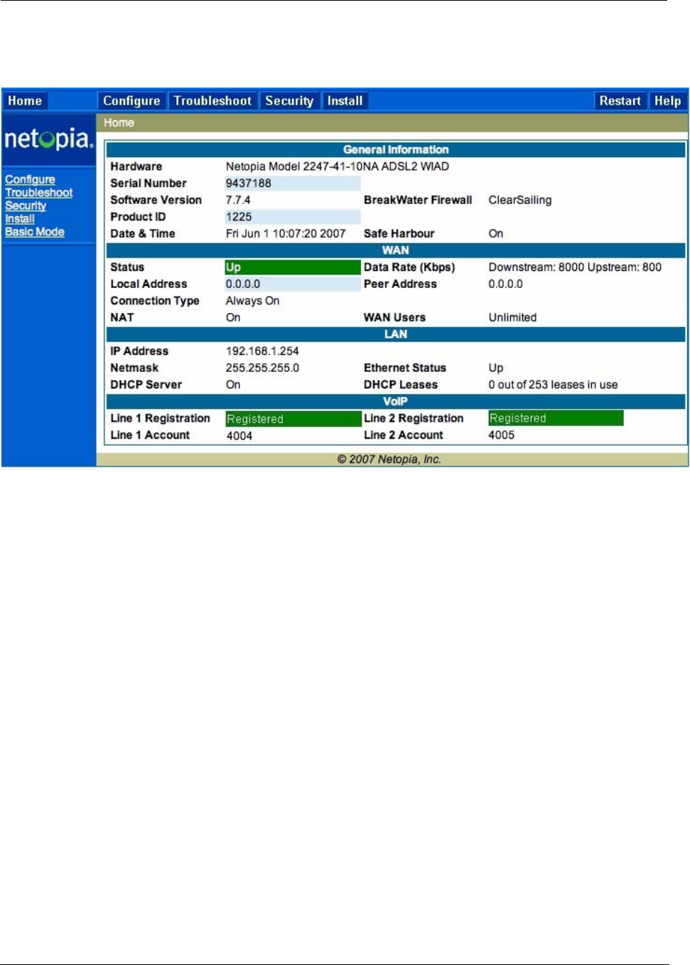
123
The Home page for a VoIP-enabled Gateway with both phone lines registered is shown below.
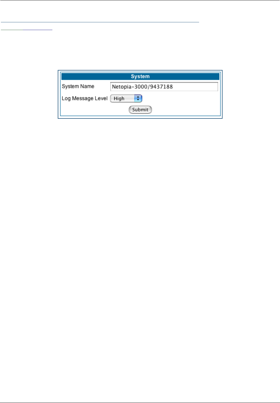
Administrator’s Handbook
124
Link: System
The System Name defaults to your Gateway's factory identifier combined with its serial number. Some
cable-oriented Service Providers use the System Name as an important identification and support parame-
ter.
The System Name can be 1 – 255 characters long; it can include embedded spaces and special charac-
ters.
The Log Message Level alters the severity at which messages are collected in the Gateway's system log.
Do not alter this field unless instructed by your Support representative.
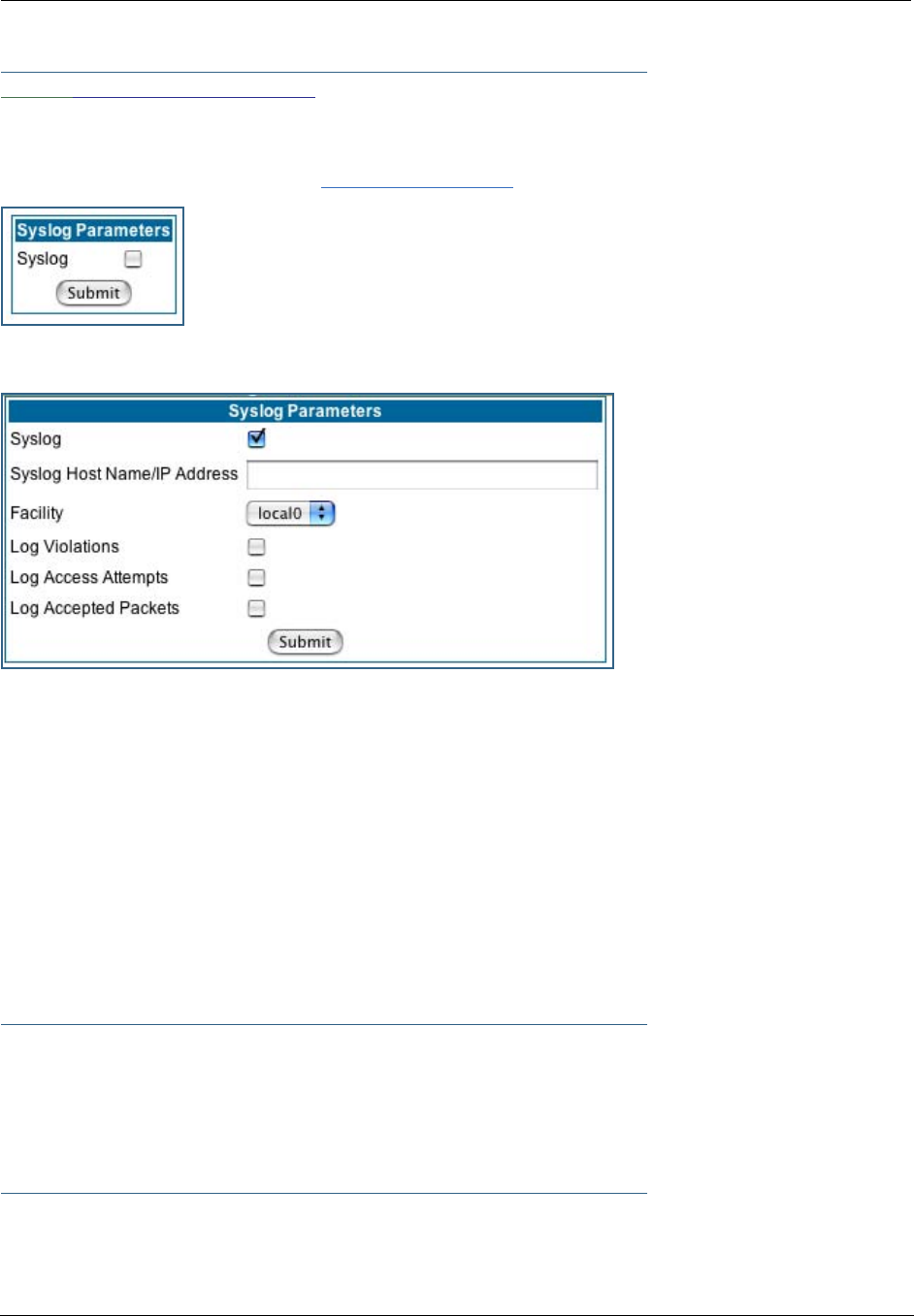
125
Link: Syslog Parameters
You can configure a UNIX-compatible syslog client to report a number of subsets of the events entered in
the Gateway’s WAN Event History. Syslog sends log-messages to a host that you specify.
To enable syslog logging, click on the Syslog Parameters link.
Check the Syslog checkbox.
The screen expands.
•Syslog: Enable syslog logging in the system.
•Syslog Host Name/IP Address: Enter the name or the IP Address of the host that should receive sys-
log messages.
•Facility: From the pull-down menu, select the Syslog facility to be used by the router when generating
syslog messages. Options are local0 through local7.
•Log Violations: If you check this checkbox, the Gateway will generate messages whenever a packet is
discarded because it violates the router's security policy.
•Log Access Attempts: If you check this checkbox, the Gateway will generate messages whenever a
packet attempts to access the router or tries to pass through the router. This option is disabled by
default.
•Log Accepted Packets: If you check this checkbox, the Gateway will generate messages whenever a
packet accesses the router or passes through the router. This option is disabled by default.
☛ NOTE:
Syslog needs to be enabled to comply with logging requirements mentioned in The Modular
Firewall Certification Criteria - Baseline Module - version 4.1 (specified by ICSA Labs).
For more information, please go to the following URL:
http://www.icsalabs.com/icsa/docs/html/communities/firewalls/pdf/4.1/baseline.pdf

Administrator’s Handbook
126
Log Event Messages
Administration Related Log Messages
1. administrative
access attempted:
This log-message is generated whenever the user attempts to access
the router's management interface.
2. administrative
access authenticated
and allowed:
This log-message is generated whenever the user attempts to access
the router's management interface and is successfully authenticated
and allowed access to the management interface.
3. administrative
access allowed:
If for some reason, a customer does not want password protection for
the management interface, this log-message is generated whenever
any user attempts to access the router's management interface and is
allowed access to the management interface.
4. administrative
access denied -
invalid user name:
This log-message is generated whenever the user tries to access the
router's management interface and authentication fails due to incor-
rect user-name.
5. administrative
access denied -
invalid password:
This log-message is generated whenever the user tries to access the
router's management interface and authentication fails due to incor-
rect password.
6. administrative
access denied - telnet
access not allowed:
This log-message is generated whenever the user tries to access the
router's Telnet management interface from a Public interface and is
not permitted since Remote Management is disabled.
7. administrative
access denied - web
access not allowed:
This log-message is generated whenever the user tries to access the
router's HTTP management interface from a Public interface and is
not permitted since Remote Management is disabled.
System Log Messages
1. Received NTP Date
and Time:
This log-message is generated whenever NTP receives Date and
time from the server.
2. EN: IP up: This log-message is generated whenever Ethernet WAN comes up.
3. WAN: Ethernet
WAN1 activated at
100000 Kbps:
This log-message is generated when the Ethernet WAN Link is up.
4. Device Restarted: This log-message is generated when the router has been restarted.
DSL Log Messages (most common):
1. WAN: Data link
activated at <Rate>
Kbps (rx/tx)
This log message is generated when the DSL link comes up.
2.WAN: Data link
deactivated
This log message is generated when the DSL link goes down.
3. RFC1483 up This log message is generated when RFC1483 link comes up.
4. RFC1483-<WAN-
instance>: IP down
This log message is generated when RFC1483 link goes down.

127
5. PPP: Channel <ID>
up Dialout Profile
name: <Profile Name>
This log message is generated when a PPP channel comes up.
6. PPP-<WAN
Instance> down:
<Reason>
This log message is generated when a PPP channel goes down. The
reason for the channel going down is displayed as well.
Access-related Log Messages
1. permitted: This log-message is generated whenever a packet is allowed to
traverse router-interfaces or allowed to access the router itself.
2. attempt: This log-message is generated whenever a packet attempts to
traverse router-interfaces or attempts to access the router itself.
3. dropped - violation
of security policy:
This log-message is generated whenever a packet, traversing the
router or destined to the router itself, is dropped by the firewall
because it violates the expected conditions.
4. dropped - invalid
checksum:
This log-message is generated whenever a packet, traversing the
router or destined to the router itself, is dropped because of invalid IP
checksum.
5. dropped - invalid
data length:
This log-message is generated whenever a packet, traversing the
router or destined to the router itself, is dropped because the IP length
is greater than the received packet length or if the length is too small
for an IP packet.
6. dropped - frag-
mented packet:
This log-message is generated whenever a packet, traversing the
router, is dropped because it is fragmented, stateful inspection is
turned ON on the packet's transmit or receive interface, and deny-
fragment option is enabled.
7. dropped - cannot
fragment:
This log-message is generated whenever a packet traversing the
router is dropped because the packet cannot be sent without frag-
mentation, but the do not fragment bit is set.
8. dropped - no route
found:
This log-message is generated whenever a packet, traversing the
router or destined to the router itself, is dropped because no route is
found to forward the packet.
9. dropped - invalid IP
version:
This log-message is generated whenever a packet, traversing the
router or destined to the router itself, is dropped because the IP ver-
sion is not 4.
10. dropped - possi-
ble land attack:
This log-message is generated whenever a packet, traversing the
router or destined to the router itself, is dropped because the packet is
TCP/UDP packet and source IP Address and source port equals the
destination IP Address and destination port.
11. TCP SYN flood
detected:
This log-message is generated whenever a SYN packet destined to
the router's management interface is dropped because the number of
SYN-sent and SYN-receives exceeds one half the number of allow-
able connections in the router.
12. Telnet receive DoS
attack - packets
dropped:
This log-message is generated whenever TCP packets destined to
the router's telnet management interface are dropped due to over-
whelming receive data.
DSL Log Messages (most common):

Administrator’s Handbook
128
13. dropped - reas-
sembly timeout:
This log-message is generated whenever packets, traversing the
router or destined to the router itself, are dropped because of reas-
sembly timeout.
14. dropped - illegal
size:
This log-message is generated whenever packets, traversing the
router or destined to the router itself, are dropped during reassembly
because of illegal packet size in a fragment.
Access-related Log Messages
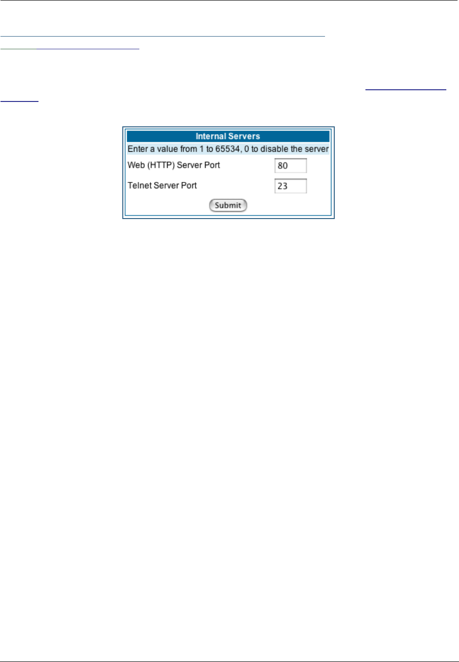
129
Link: Internal Servers
Your Gateway ships with an embedded Web server and support for a Telnet session, to allow ease of use
for configuration and maintenance. The default ports of 80 for HTTP and 23 for Telnet may be reassigned.
This is necessary if a pinhole is created to support applications using port 80 or 23. See “Pinholes” on
page 82. for more information on Pinhole configuration.
Web (HTTP) Server Port: To reassign the port number used to access the Motorola Netopia® embedded
Web server, change this value to a value greater than 1024. When you next access the embedded Motorola
Netopia® Web server, append the IP address with <port number>, (e.g. Point your browser to http://
210.219.41.20:8080).
Telnet Server Port: To reassign the port number used to access your Motorola Netopia® embedded Telnet
server, change this value to a value greater than 1024. When you next access the Motorola Netopia®
embedded Telnet server, append the IP address with <port number>, (e.g. telnet 210.219.41.20 2323).
You can also use the LAN-side address of the Gateway, 192.168.1.x:8100 to access the web server and
192.168.1.x:2323 to access the telnet server. The value of 0 for an internal server port will disable that
server. You can disable Telnet or Web, but not both. If you disabled both ports, you would not be able to
reconfigure the unit without pressing the reset button.
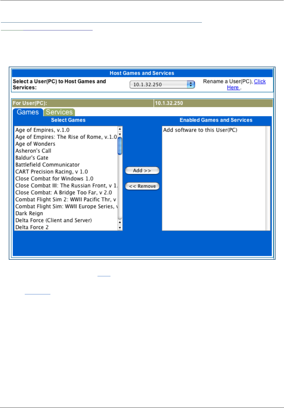
Administrator’s Handbook
130
Link: Software Hosting
Software Hosting allows you to host internet applications when NAT is enabled. User(PC) specifies the
machine on which the selected software is hosted. You can host different games and software on different
PCs.
To select the games or software that you want to host for a specific PC, highlight the name(s) in the box on
the left side of the screen. Click the Add button to select the software that will be hosted.
To remove a game or software from the hosted list, highlight the game or software you want to remove and
click the Remove button.

131
List of Supported Games and Software
Age of Empires, v.1.0 Age of Empires: The Rise of
Rome, v.1.0
Age of Wonders
Asheron's Call Baldur's Gate Battlefield Communicator
Buddy Phone Calista IP Phone CART Precision Racing, v 1.0
Citrix Metaframe/ICA Client Close Combat for Windows 1.0 Close Combat: A Bridge Too
Far, v 2.0
Close Combat III: The Russian
Front, v 1.0
Combat Flight Sim: WWII
Europe Series, v 1.0
Combat Flight Sim 2: WWII
Pacific Thr, v 1.0
Dark Reign Delta Force (Client and Server) Delta Force 2
Diablo II Server Dialpad DNS Server
Dune 2000 eDonkey 2000 eMule
F-16, Mig 29 F-22, Lightning 3 Fighter Ace II
FTP GNUtella H.323 compliant (Netmeeting,
CUSeeME)
Half Life Hellbender for Windows, v 1.0 Heretic II
Hexen II Hotline Server HTTP
HTTPS ICQ 2001b ICQ Old
IMAP Client IMAP Client v.3 Internet Phone
IPSec IPSec IKE Jedi Knight II: Jedi Outcast
Kali KazaA LimeWire
Links LS 2000 Mech Warrior 3 Mech Warrior 4: Vengeance
Medal of Honor Allied Assault Microsoft Flight Simulator 98 Microsoft Flight Simulator
2000
Microsoft Golf 1998 Edition, v
1.0
Microsoft Golf 1999 Edition Microsoft Golf 2001 Edition
Midtown Madness, v 1.0 Monster Truck Madness, v 1.0 Monster Truck Madness 2, v
2.0
Motocross Madness 2, v 2.0 Motocross Madness, v 1.0 MSN Game Zone
MSN Game Zone (DX7 an 8
Play)
Need for Speed 3, Hot Pursuit Need for Speed, Porsche
Net2Phone NNTP Operation FlashPoint
Outlaws pcAnywhere (incoming) POP-3
PPTP Quake II Quake III
Rainbow Six RealAudio Return to Castle Wolfenstein
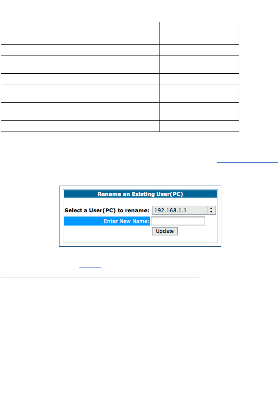
Administrator’s Handbook
132
Rename a User(PC)
If a PC on your LAN has no assigned host name, you can assign one by clicking the Rename a User(PC)
link.
To rename a server, select the server from the pull-down menu. Then type a new name in the text box below
the pull-down menu. Click the Update button to save the new name.
☛ NOTE:
The new name given to a server is only known to Software Hosting. It is not used as an identi-
fier in other network functions, such as DNS or DHCP.
Roger Wilco Rogue Spear ShoutCast Server
SMTP SNMP SSH server
StarCraft Starfleet Command StarLancer, v 1.0
Telnet TFTP Tiberian Sun: Command and
Conquer
Timbuktu Total Annihilation Ultima Online
Unreal Tournament Server Urban Assault, v 1.0 VNC, Virtual Network Comput-
ing
Westwood Online, Command
and Conquer
Win2000 Terminal Server XBox Live Games
Yahoo Messenger Chat Yahoo Messenger Phone ZNES
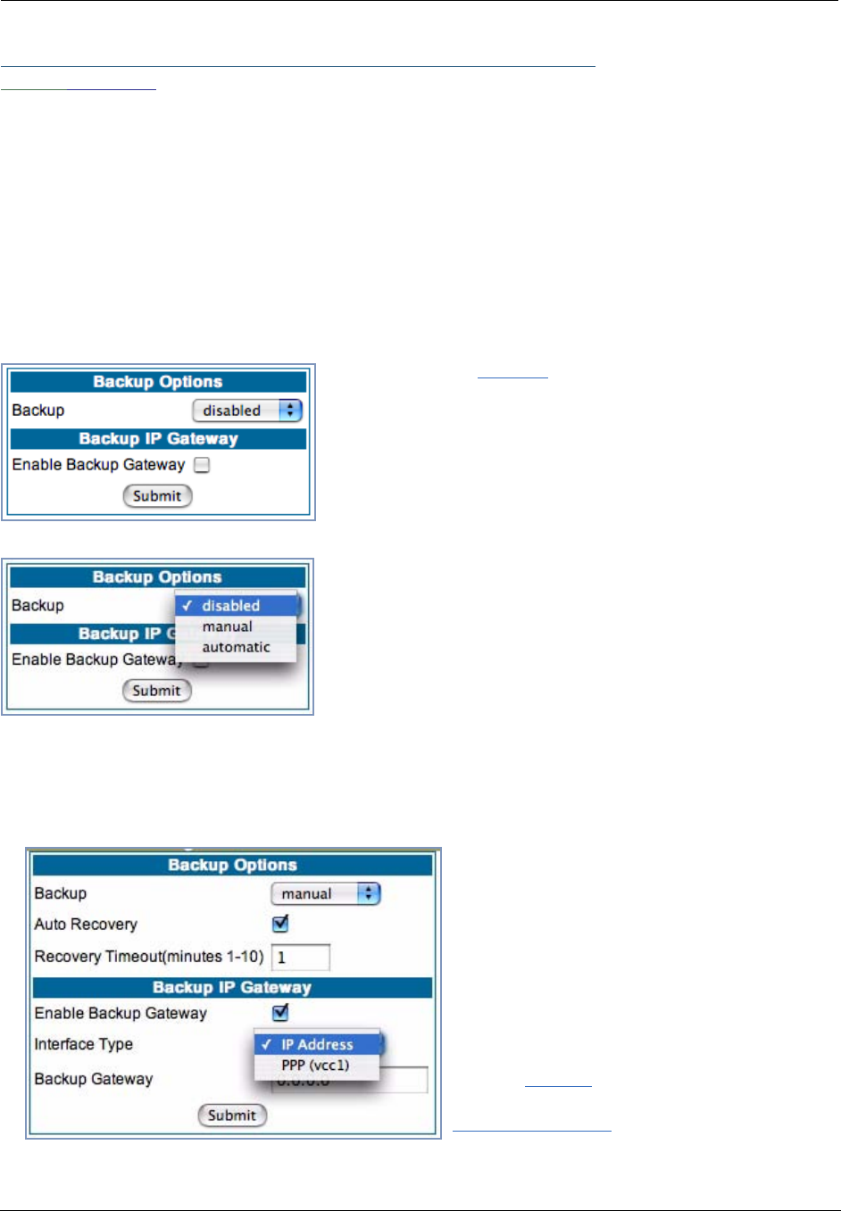
133
Link: Backup
The purpose of Backup is to provide a recovery mechanism in the event that the primary connection fails. A
failure can be either line loss, for example by central site switch failure or physical cable breakage, or loss
of end-to-end connectivity. Detection of one of these failures causes the Gateway to switch from using the
primary DSL WAN connection to an alternate gateway on the Ethernet LAN. In the event of a loss of primary
connectivity you have the option of switching back to the primary circuit automatically once it has recovered
its connection.
A typical application would be to have a LAN connection from your Gateway to another Gateway that has, for
example, another DSL modem or Gateway connection to the Internet, and designating the second gateway
as the backup gateway. Should the primary WAN connection fail, traffic would be automatically redirected
through your alternate gateway device to maintain Internet connectivity.
When you click the Backup link, the Backup Options page
appears.
Select either manual or automatic from the pull-down menu.
•If you choose manual, you will have to switch manually to your
alternate gateway in the event of a connection failure.
•For fail-over purposes, choose automatic.
Manual options
If you choose manual, you can also choose Auto Recovery. If you chose Auto Recovery, enter the number
of minutes that the system should wait before it assumes that a connection has been re-established. This
allows you to be sure that the primary WAN connection is well re-established before the Gateway switches
back to it from the backup mode. Minimum value is one minute.
•Check the Enable Backup Gateway checkbox.
•From the pull-down menu, select the Interface
Type to which you want to direct the backup con-
nection. If you have defined multiple VCCs, you
can choose a secondary one. Otherwise, to
backup to an IP device on the LAN, choose IP
Address.
The screen expands to allow you to enter an IP
address of your Backup Gateway.
Click the Submit button; click the Alert icon,
and in the resulting page, click the
Save and Restart link.
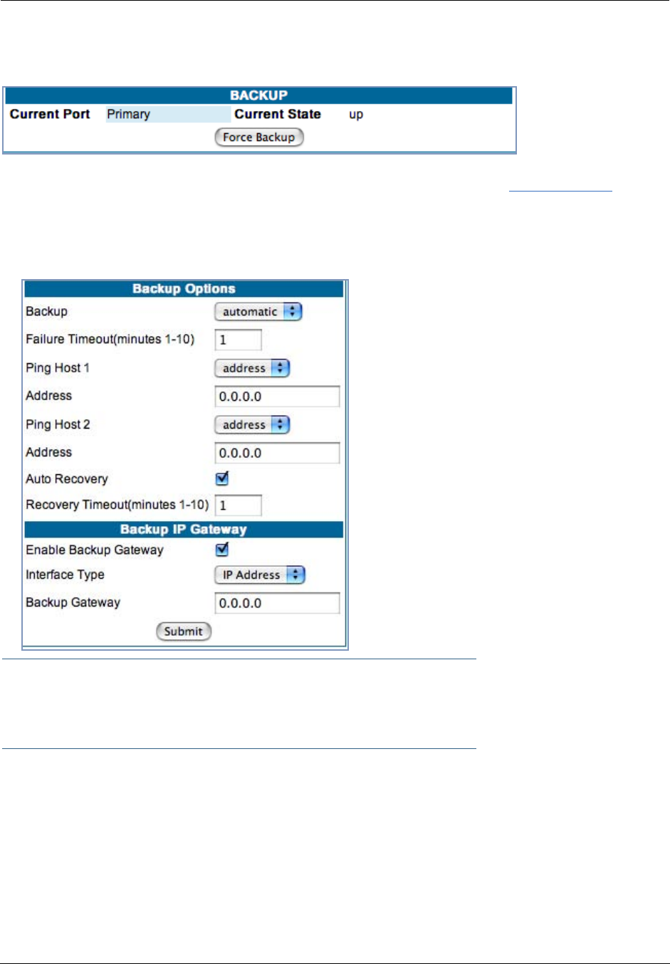
Administrator’s Handbook
134
Once Backup is configured, a new field appears in the Home Page.
If your DSL WAN link fails, you can switch to your Backup Gateway by clicking the Force Backup button.
Automatic options
If you select automatic as your Backup option, the screen expands to allow you to enter additional informa-
tion.
•Failure Timeout (minutes 1-10) – Enter the
number of minutes you want the system to wait
before the backup port becomes enabled in the
event of primary line failure. This allows you to be
sure the WAN connection is not merely briefly
interrupted before the gateway switches to
backup mode.
•Ping Host 1 and Ping Host 2 – Select address
or name from the pull-down menu enter IP
address(es) or resolvable DNS name(s) that the
Gateway will ping.
The Gateway will ping both addresses simulta-
neously at five-second intervals, recording the
ping responses from each host. The Gateway will
proceed into backup mode only if neither of the
configured remote hosts responds.
☛ Note:
For best results, enter an IP address and not a host name. If a host name is used it may not
be resolvable, and may keep the interface down.
•While the Gateway is in backup mode, it will continue to ping both hosts via the primary interface. If
either host responds to a ping and the Auto Recovery checkbox is checked, the Gateway will revert to
the primary interface.
•If you chose Auto Recovery, select Recovery Timeout (minutes1-10). Enter the number of minutes you
want the system to wait before attempting to switch back to the WAN connection. This allows you to be
sure that the WAN connection is well re-established before the gateway switches back to it from the
backup mode.
•Check the Enable Backup Gateway checkbox
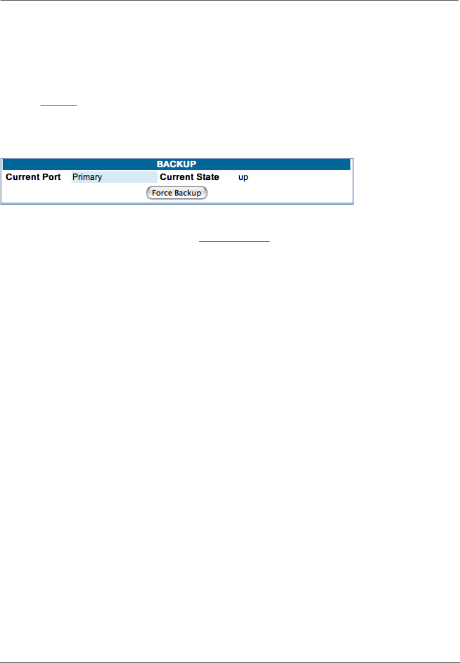
135
•From the pull-down menu, select the Interface Type to which you want to direct the backup connection.
If you have defined multiple VCCs, you can choose a secondary one. Otherwise, to backup to an IP
device on the LAN, choose IP Address.
The screen expands to allow you to enter an IP address of your Backup Gateway.
Click the Submit button; click the Alert icon, and in the resulting page, click the
Save and Restart link.
Once Backup is configured, a new field appears in the Home Page.
For automatic mode, it should not be necessary to switch to Backup manually. However, you can force a
switch to your Backup Gateway by clicking the Force Backup button.
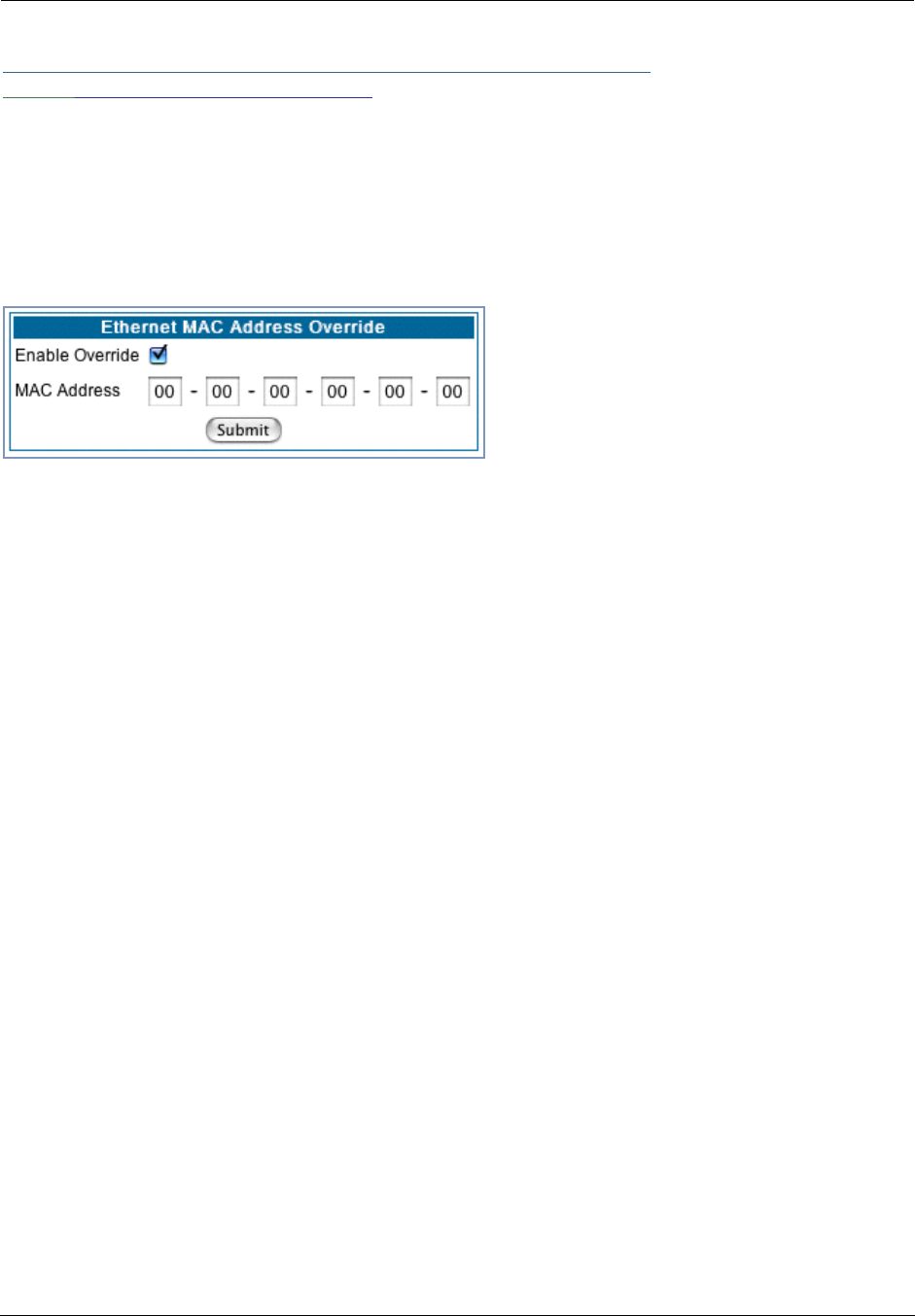
Administrator’s Handbook
136
Link: Ethernet MAC Override
(Only available on models with Ethernet WAN interfaces, such as the 338X-series or VDSL Gateways.)
Your Gateway comes with its own MAC (Media Access Control) address, also called the Hardware Address,
a 12 character number unique for each LAN-connected device.
Your Service Provider, particularly cable service providers, may instruct you to override the default MAC
address.
If so, check the Enable Override checkbox, and enter the new MAC address in the field provided.
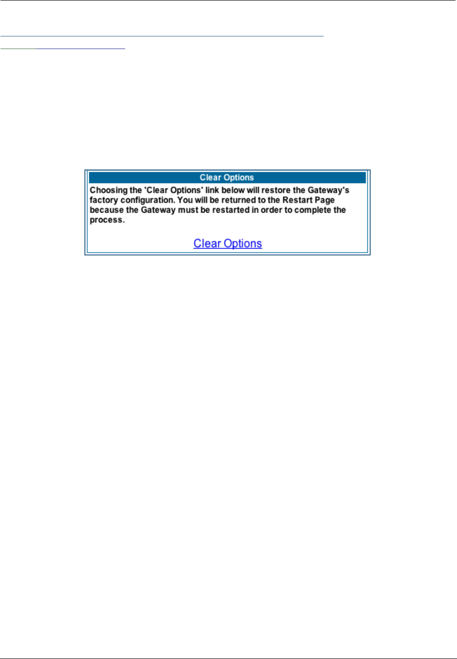
137
Link: Clear Options
To restore the factory configuration of the Gateway, choose Clear Options. You may want to upload your
configuration to a file before performing this function. You can do this using the upload command via the
command-line interface. See the upload command on page 238.
Clear Options does not clear feature keys or affect the software image.
You must restart the Gateway for Clear Options to take effect.

Administrator’s Handbook
138
Link: Time Zone
When you click the Time Zone link, the Time Zone page appears.
You can set your local time zone by selecting the number of hours your time zone is distant from Greenwich
Mean Time (GMT +12 – -12) from the pull-down menu. This allows you to set the time zone for access con-
trols and in general.
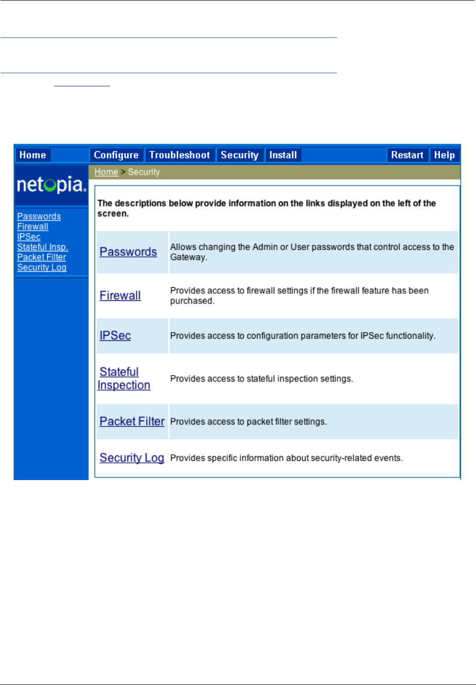
139
Security
Button: Security
The Security features are available by clicking on the Security toolbar button. Some items of this category
do not appear when you log on as User.
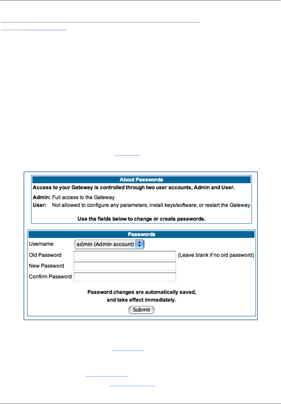
Administrator’s Handbook
140
Link: Passwords
Access to your Gateway may be controlled through two optional user accounts, Admin and User. When you
first power up your Gateway, you create a password for the Admin account. The User account does not
exist by default. As the Admin, a password for the User account can be entered or existing passwords
changed.
Create and Change Passwords. You can establish different levels of access security to protect
your Motorola Netopia® Gateway settings from unauthorized display or modification.
•Admin level privileges let you display and modify all settings in the Motorola Netopia® Gateway (Read/
Write mode). The Admin level password is created when you first access your Gateway.
•User level privileges let you display (but not change) settings of the Motorola Netopia® Gateway. (Read
Only mode)
To prevent anyone from observing the password you enter, characters in the old and new password fields
are not displayed as you type them.
To display the Passwords window, click the Security toolbar button on the Home page.
Use the following procedure to change existing passwords or add the User password for your Motorola
Netopia® Gateway:
1. Select the account type from the Username pull-down list.
Choose from Admin or User.
2. If you assigned a password to the Motorola Netopia® Gateway previously, enter your
current password in the Old Password field.
3. Enter your new password in the New Password field.
Motorola Netopia®’s rules for a Password are:

141
•It can have up to eight alphanumeric characters.
•It is case-sensitive.
4. Enter your new password again in the Confirm Password field.
You confirm the new password to verify that you entered it correctly the first time.
5. When you are finished, click the Submit button to store your modified configuration in
the Motorola Netopia® unit’s memory.
Password changes are automatically saved, and take effect immediately.

Administrator’s Handbook
142
Link: Firewall
Use a Motorola Netopia® Firewall
BreakWater Basic Firewall. BreakWater delivers an easily selectable set of pre-configured firewall
protection levels. For simple implementation these settings (comprised of three levels) are readily available
through Motorola Netopia®’s embedded web server interface.
BreakWater Basic Firewall’s three settings are:
•ClearSailing
ClearSailing, BreakWater's default setting, supports both inbound and outbound traffic. It is the only
basic firewall setting that fully interoperates with all other Motorola Netopia® software features.
•SilentRunning
Using this level of firewall protection allows transmission of outbound traffic on pre-configured TCP/UDP
ports. It disables any attempt for inbound traffic to identify the Gateway. This is the Internet equivalent
of having an unlisted number.
•LANdLocked
The third option available turns off all inbound and outbound traffic, isolating the LAN and disabling all
WAN traffic.
☛ NOTE:
BreakWater Basic Firewall operates independent of the NAT functionality on the Gateway.
Configuring for a BreakWater Setting
Use these steps to establish a firewall setting:
1. Ensure that you have enabled the BreakWater basic firewall with the appropriate fea-
ture key.
See See “Use Motorola Netopia® Software Feature Keys” on page 187. for reference.
NOTE: The firewall is now keyed on by default on the 2200-Series Gateways.
2. Click the Security toolbar button.
3. Click Firewall.
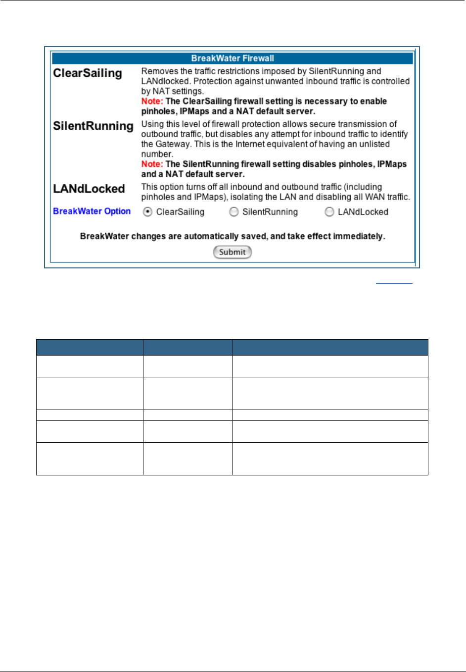
143
4. Click on the radio button to select the protection level you want. Click Submit.
Changing the BreakWater setting does not require a restart to take effect. This makes it easy to change
the setting “on the fly,” as your needs change.
TIPS for making your BreakWater Basic Firewall Selection
Basic Firewall Background
As a device on the Internet, a Motorola Netopia® Gateway requires an IP address in order to send or
receive traffic.
The IP traffic sent or received have an associated application port which is dependent on the nature of the
connection request. In the IP protocol standard the following session types are common applications:
By receiving a response to a scan from a port or series of ports (which is the expected behavior according
to the IP standard), hackers can identify an existing device and gain a potential opening for access to an
internet-connected device.
Application Select this Level Other Considerations
Typical Internet usage
(browsing, e-mail)
SilentRunning
Multi-player online
gaming
ClearSailing Set Pinholes; once defined, pinholes will be
active whenever ClearSailing is set.
Restore SilentRunning when finished.
Going on vacation LANdLocked Protects your connection while your away.
Finished online use for
the day
LANdLocked This protects you instead of disconnecting your
Gateway connection.
Chatting online or using
instant messaging
ClearSailing Set Pinholes; once defined, pinholes will be
active whenever ClearSailing is set.
Restore SilentRunning when finished.
•ICMP •HTTP •FTP
•SNMP •telnet •DHCP

Administrator’s Handbook
144
To protect LAN users and their network from these types of attacks, BreakWater offers three levels of
increasing protection.
The following tables indicate the state of ports associated with session types, both on the WAN side
and the LAN side of the Gateway.
This table shows how inbound traffic is treated. Inbound means the traffic is coming from the WAN into the
WAN side of the Gateway.
This table shows how outbound traffic is treated. Outbound means the traffic is coming from the LAN-side
computers into the LAN side of the Gateway.
Gateway: WAN Side
BreakWater Setting >> ClearSailing SilentRunning LANdLocked
Port Session Type --------------Port State-----------------------
20 ftp data Enabled Disabled Disabled
21 ftp control Enabled Disabled Disabled
23 telnet external Enabled Disabled Disabled
23 telnet Motorola Netopia®
server
Enabled Disabled Disabled
80 http external Enabled Disabled Disabled
80 http Motorola Netopia® server Enabled Disabled Disabled
67 DHCP client Enabled Enabled Disabled
68 DHCP server Not Applicable Not Applicable Not Applicable
161 snmp Enabled Disabled Disabled
ping (ICMP) Enabled Disabled Disabled
Gateway: LAN Side
BreakWater Setting >> ClearSailing SilentRunning LANdLocked
Port Session Type --------------Port State-----------------------
20 ftp data Enabled Enabled Disabled
21 ftp control Enabled Enabled Disabled
23 telnet external Enabled Enabled Disabled
23 telnet Motorola Netopia®
server
Enabled Enabled Enabled
80 http external Enabled Enabled Disabled
80 http Motorola Netopia® server Enabled Enabled Enabled
67 DHCP client Not Applicable Not Applicable Not Applicable
68 DHCP server Enabled Enabled Enabled
161 snmp Enabled Enabled Enabled
ping (ICMP) Enabled Enabled WAN - Disabled
LAN -
Local Address
Only

145
☛ NOTE:
The Gateway’s WAN DHCP client port in SilentRunning mode is enabled. This feature allows
end users to continue using DHCP-served IP addresses from their Service Providers, while hav-
ing no identifiable presence on the Internet.

Administrator’s Handbook
146
Link: IPSec
When you click on the IPSec link, the IPSec configuration screen appears.
Your Gateway can support two mechanisms for IPSec tunnels:
•IPSec PassThrough supports Virtual Private Network (VPN) clients running on LAN-connected comput-
ers. Normally, this feature is enabled.
You can disable it if your LAN-side VPN client includes its own NAT interoperability option.
Uncheck the Enable IPSec Passthrough checkbox.
•SafeHarbour VPN IPSec is a keyed feature that you must purchase. (See “Install Key” on page 187.) It
enables Gateway-terminated VPN support.
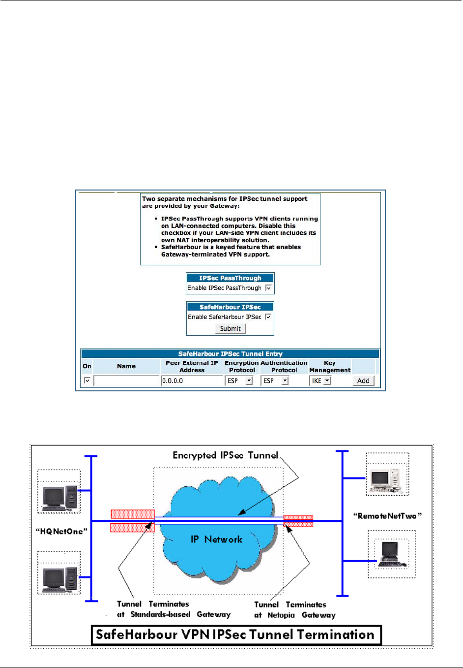
147
SafeHarbour IPSec VPN
SafeHarbour VPN IPSec Tunnel provides a single, encrypted tunnel to be terminated on the Gateway, mak-
ing a secure tunnel available for all LAN- connected users. This implementation offers the following:
•Eliminates the need for VPN client software on individual PCs.
•Reduces the complexity of tunnel configuration.
•Simplifies the ongoing maintenance for secure remote access.
If you have purchased the SafeHarbour IPSec feature key, the IPSec configuration screen offers additional
options.
A typical SafeHarbour configuration is shown below:

Administrator’s Handbook
148
Configuring a SafeHarbour VPN
Use the following procedure to configure your SafeHarbour tunnel.
1. Obtain your configuration information from your network administrator.
The tables “Parameter Descriptions” on page 151 describe the various parameters that may be required
for your tunnel. Not all of them need to be changed from the defaults for every VPN tunnel. Consult with
your network administrator.
2. Complete the Parameter Setup worksheet “IPSec Tunnel Details Parameter Setup Work-
sheet” on page 149.
The worksheet provides spaces for you to enter your own specific values. You can print the page for easy
reference. IPSec tunnel configuration requires precise parameter setup between VPN devices. The Setup
Worksheet (page 149) facilitates setup and assures that the associated variables are identical.

149
Table 1: IPSec Tunnel Details Parameter Setup Worksheet
Parameter Motorola Netopia®
Gateway Peer Gateway
Name
Peer Internal Network
Peer Internal Netmask
NAT Enable On/Off
PAT Address
Negotiation Method Main/Aggressive
Local ID Type IP Address
Subnet
Hostname
ASCII
Local ID Address/Value
Local ID Mask
Remote ID Type IP Address
Subnet
Hostname
ASCII
Remote ID Address/Value
Remote ID Mask
Pre-Shared Key Type HEX
ASCII
Pre-Shared Key
DH Group 1/2/5
PFS Enable Off/On
SA Encrypt Type DES
3DES
SA Hash Type MD5
SHA1
Invalid SPI Recovery Off/On
Soft MBytes 1 - 1000000
Soft Seconds 60 - 1000000
Hard MBytes 1 - 1000000
Hard Seconds 60 - 1000000
IPSec MTU 100 - 1500 (default)
Xauth Enable Off/On
Xauth Username
Xauth Password
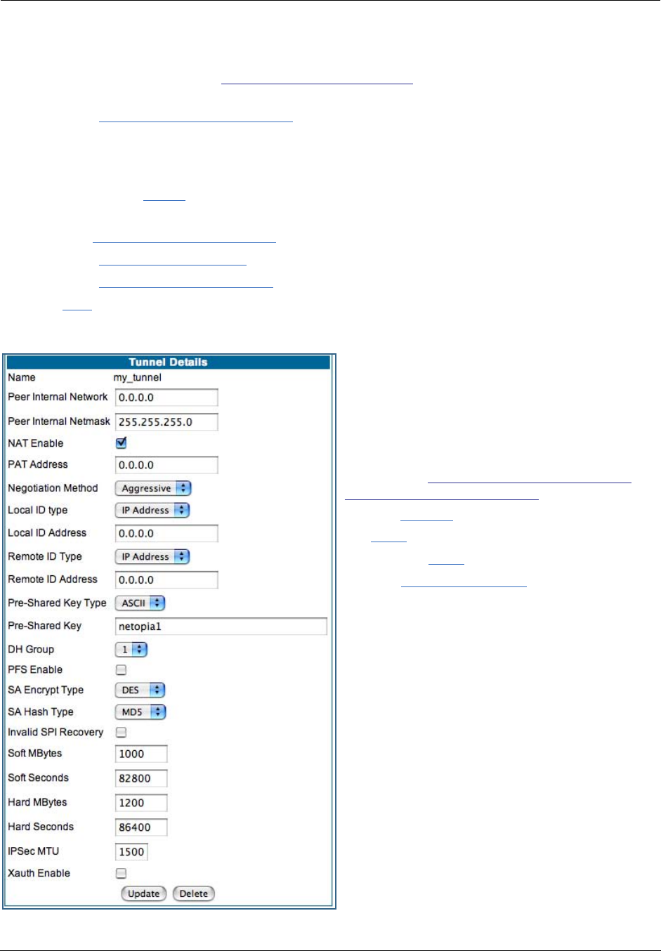
Administrator’s Handbook
150
3. Be sure that you have SafeHarbour VPN enabled.
SafeHarbour is a keyed feature. See “Install Key” on page 187. for information concerning installing
Motorola Netopia® Software Feature Keys.
4. Check the Enable SafeHarbour IPSec checkbox.
Checking this box will automatically display the SafeHarbour IPSec Tunnel Entry parameters.
Enter the initial group of tunnel parameters. Refer to your Setup Worksheet and the “Parameter
Descriptions” on page 151 as required.
5. Enter the tunnel Name.
This parameter does not have to match the peer/remote VPN device.
6. Enter the Peer External IP Address.
7. Select the Encryption Protocol from the pull-down menu.
8. Select the Authentication Protocol from the pull-down menu.
9. Click Add.
The Tunnel Details page appears.
10.Make the Tunnel Details entries.
Enter or select the required settings.
Soft MBytes, Soft Seconds, Hard MBytes, and
Hard Seconds values do not have to match the
peer/remote VPN device.
Refer to your “IPSec Tunnel Details Parameter
Setup Worksheet” on page 149.)
11.Click Update.
The Alert button appears.
12.Click the Alert
button.
13.Click Save and Restart.
Your SafeHarbour IPSec VPN tunnel is fully config-
ured.

151
Parameter Descriptions
The following tables describe SafeHarbour’s parameters that are used for an IPSec VPN tunnel configura-
tion:
Table 2: IPSec Configuration page parameters
Field Description
Name The Name parameter refers to the name of the configured tunnel. This is
mainly used as an identifier for the administrator. The Name parameter is
an ASCII value and is limited to 31 characters. The tunnel name does not
need to match the peer gateway.
Peer External IP
Address
The Peer External IP Address is the public, or routable IP address of the
remote gateway or VPN server you are establishing the tunnel with.
Encryption
Protocol
Encryption protocol for the tunnel session.
Parameter values supported include NONE or ESP.
Authentication
Protocol
Authentication Protocol for IP packet header. The three parameter values
are None, Encapsulating Security Payload (ESP) and Authentication Header
(AH)
Key Management The Key Management algorithm manages the exchange of security keys in
the IPSec protocol architecture. SafeHarbour supports the standard Inter-
net Key Exchange (IKE)
Table 3: IPSec Tunnel Details page parameters
Field Description
Name The Name parameter refers to the name of the configured tunnel. This is
mainly used as an identifier for the administrator. The Name parameter is
an ASCII value and is limited to 31 characters. The tunnel name does not
need to match the peer gateway.
Peer Internal
Network
The Peer Internal IP Network is the private, or Local Area Network (LAN)
address of the remote gateway or VPN Server you are communicating with.
Peer Internal
Netmask
The Peer Internal IP Netmask is the subnet mask of the Peer Internal IP
Network.
NAT enable Turns NAT on or off for this tunnel.
PAT Address If NAT is enabled, this field appears. You can specify a Port Address Trans-
lation (PAT) address or leave the default all-zeroes (if Xauth is enabled). If
you leave the default. the address will be requested from the remote router
and dynamically applied to the Gateway.
Negotiation
Method
This parameter refers to the method used during the Phase I key
exchange, or IKE process. SafeHarbour supports Main or Aggressive
Mode. Main mode requires 3 two-way message exchanges while Aggres-
sive mode only requires 3 total message exchanges.
Local ID type If Aggressive mode is selected as the Negotiation Method, this option
appears. Selection options are: IP Address, Subnet, Hostname, ASCII
Local ID Address/
Value
If Aggressive mode is selected as the Negotiation Method, this field
appears. This is the local (Gateway-side) IP address (or Name Value, if Sub-
net or Hostname are selected as the Local ID Type).

Administrator’s Handbook
152
Local ID Mask If Aggressive mode is selected as the Negotiation Method, and Subnet as
the Local ID Type, this field appears. This is the local (Gateway-side) sub-
net mask.
Remote ID Type If Aggressive mode is selected as the Negotiation Method, this option
appears. Selection options are: IP Address, Subnet, Hostname, ASCII.
Remote ID
Address/Value
If Aggressive mode is selected as the Negotiation Method, this field
appears. This is the remote (central-office-side) IP address (or Name Value,
if Subnet or Hostname are selected as the Local ID Type).
Remote ID Mask If Aggressive mode is selected as the Negotiation Method, and Subnet as
the Remote ID Type, this field appears. This is the remote (central-office-
side) subnet mask.
Pre-Shared Key
Type
The Pre-Shared Key Type classifies the Pre-Shared Key. SafeHarbour sup-
ports ASCII or HEX types
Pre-Shared Key The Pre-Shared Key is a parameter used for authenticating each side. The
value can be ASCII or Hex and a maximum of 64 characters. ASCII is case-
sensitive.
DH Group Diffie-Hellman is a public key algorithm used between two systems to
determine and deliver secret keys used for encryption. Groups 1, 2 and 5
are supported.
PFS Enable Perfect Forward Secrecy (PFS) is used during SA renegotiation. When PFS
is selected, a Diffie-Hellman key exchange is required. If enabled, the PFS
DH group follows the IKE phase 1 DH group.
SA Encrypt Type SA Encr yption Type refers to the symmetric encryption type. This encryp-
tion algorithm will be used to encrypt each data packet. SA Encryption
Type values supported include DES and 3DES.
SA Hash Type SA Hash Type refers to the Authentication Hash algorithm used during SA
negotiation. Values supported include MD5 and SHA1. N/A will display if
NONE is chosen for Auth Protocol.
Invalid SPI
Recovery
Enabling this allows the Gateway to re-establish the tunnel if either the
Motorola Netopia® Gateway or the peer gateway is rebooted.
Soft MBytes Setting the Soft MBytes parameter forces the renegotiation of the IPSec
Security Associations (SAs) at the configured Soft MByte value. The value
can be configured between 1 and 1,000,000 MB and refers to data traffic
passed. If this value is not achieved, the Hard MBytes parameter is
enforced. This parameter does not need to match the peer gateway.
Soft Seconds Setting the Soft Seconds parameter forces the renegotiation of the IPSec
Security Associations (SAs) at the configured Soft Seconds value. The
value can be configured between 60 and 1,000,000 seconds. This param-
eter does not need to match the peer gateway.
Hard MBytes Setting the Hard MBytes parameter forces the renegotiation of the IPSec
Security Associations (SAs) at the configured Hard MByte value.
The value can be configured between 1 and 1,000,000 MB and refers to
data traffic passed. This parameter does not need to match the peer gate-
way.
Hard Seconds Setting the Hard Seconds parameter forces the renegotiation of the IPSec
Security Associations (SAs) at the configured Hard Seconds value. The
value can be configured between 60 and 1,000,000 seconds This parame-
ter does not need to match the peer gateway.
Table 3: IPSec Tunnel Details page parameters

153
IPSec MTU Some ISPs require a setting of e.g. 1492 (or other value). The default
1500 is the most common and you usually don’t need to change this
unless otherwise instructed. Accepted values are from 100 – 1500.
This is the starting value that is used for the MTU when the IPSec tunnel is
installed. It specifies the maximum IP packet length for the encapsulated
AH or ESP packets sent by the router. The MTU used on the IPSec connec-
tion will be automatically adjusted based on the MTU value in any received
ICMP can't fragment error messages that correspond to IPSec traffic initi-
ated from the router. Normally the MTU only requires manual configuration
if the ICMP error messages are blocked or otherwise not received by the
router.
Xauth Enable Extended Authentication (XAuth), an extension to the Internet Key
Exchange (IKE) protocol. The Xauth extension provides dual authentication
for a remote user’s Motorola Netopia® Gateway to establish a VPN, autho-
rizing network access to the user’s central office. IKE establishes the tun-
nel, and Xauth authenticates the specific remote user's Gateway. Since
NAT is supported over the tunnel, the remote user network can have multi-
ple PCs behind the client Gateway accessing the VPN. By using XAuth, net-
work VPN managers can centrally control remote user authentication.
Xauth Username/
Password
Xauth authentication credentials.
Table 3: IPSec Tunnel Details page parameters
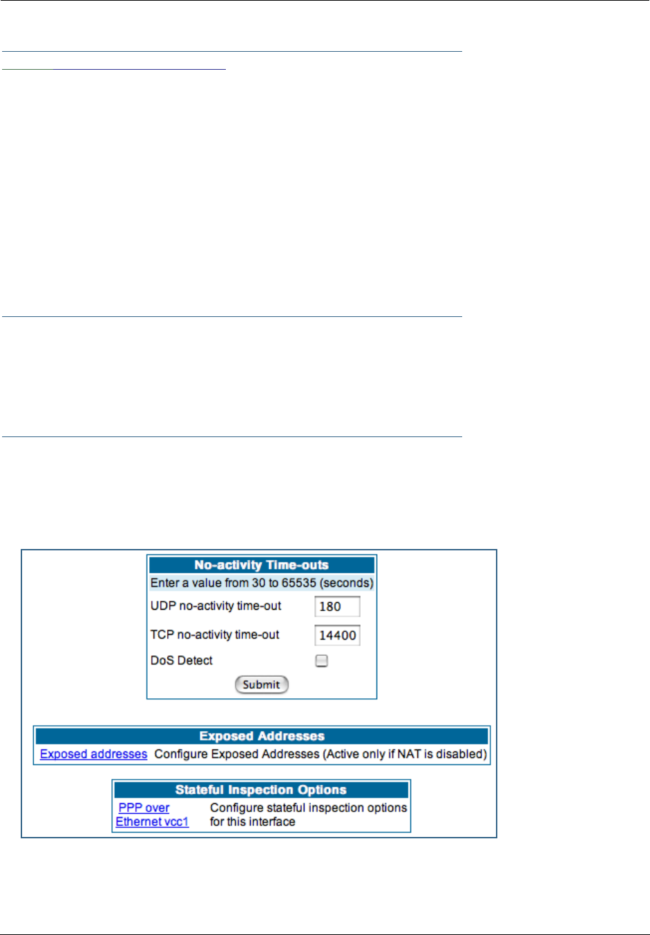
Administrator’s Handbook
154
Link: Stateful Inspection
All computer operating systems are vulnerable to attack from outside sources, typically at the operating
system or Internet Protocol (IP) layers. Stateful Inspection firewalls intercept and analyze incoming data
packets to determine whether they should be admitted to your private LAN, based on multiple criteria, or
blocked. Stateful inspection improves security by tracking data packets over a period of time, examining
incoming and outgoing packets. Outgoing packets that request specific types of incoming packets are
tracked; only those incoming packets constituting a proper response are allowed through the firewall.
Stateful inspection is a security feature that prevents unsolicited inbound access when NAT is disabled. You
can configure UDP and TCP “no-activity” periods that will also apply to NAT time-outs if stateful inspection is
enabled on the interface. Stateful Inspection parameters are active on a WAN interface only if enabled on
your Gateway. Stateful inspection can be enabled on a WAN interface whether NAT is enabled or not.
Stateful Inspection Firewall installation procedure
☛ NOTE:
Installing Stateful Inspection Firewall is mandatory to comply with Required Services Security
Policy - Residential Category module - Version 4.1 (specified by ICSA Labs)
For more information please go to the following URL:
http://www.icsalabs.com/icsa/docs/html/communities/firewalls/pdf/4.1/baseline.pdf
1. Access the router through the web interface from the private LAN.
DHCP server is enabled on the LAN by default.
2. The Gateway’s Stateful Inspection feature must be enabled in order to prevent TCP,
UDP and ICMP packets destined for the router or the private hosts.
This can be done by navigating to Expert Mode -> Security -> Stateful Inspection.
•UDP no-activity time-out: The time in seconds after which a UDP session will be terminated, if there is
no traffic on the session.
•TCP no-activity time-out: The time in seconds after which an TCP session will be terminated, if there
is no traffic on the session.
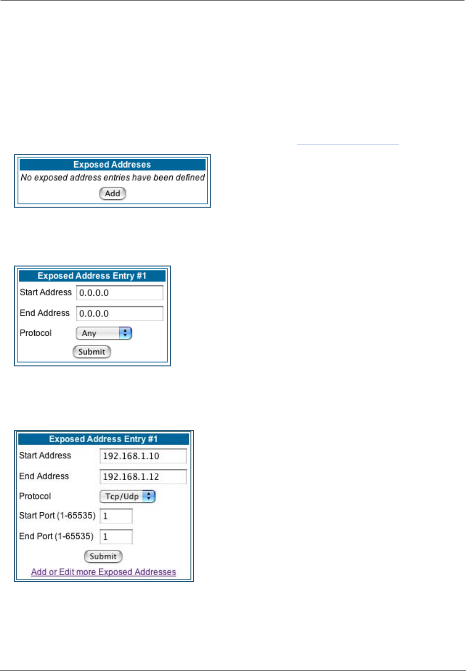
155
•DoS Detect: If you check this checkbox, the Gateway will monitor packets for Denial of Service attacks.
•Exposed Addresses: The hosts specified in Exposed Addresses will be allowed to receive inbound traf-
fic even if there is no corresponding outbound traffic. This is active only if NAT is disabled on a WAN
interface.
•Stateful Inspection Options: Enable and configure stateful inspection on a WAN interface.
Exposed Addresses
You can specify the IP addresses you want to expose by clicking the Exposed addresses link.
Add, Edit, or delete exposed addresses options are active only if NAT is disabled on a WAN interface. The
hosts specified in exposed addresses will be allowed to receive inbound traffic even if there is no corre-
sponding outbound traffic.
•Start Address: Start IP Address of the exposed host range.
•End Address: End IP Address of the exposed host range
•Protocol: Select the Protocol of the traffic to be allowed to the host range from the pull-down menu.
Options are Any, TCP, UDP, or TCP/UDP.
•Start Port: Start port of the range to be allowed to the host range. The acceptable range is from 1 -
65535
•End Port: Protocol of the traffic to be allowed to the host range. The acceptable range is from 1 - 65535
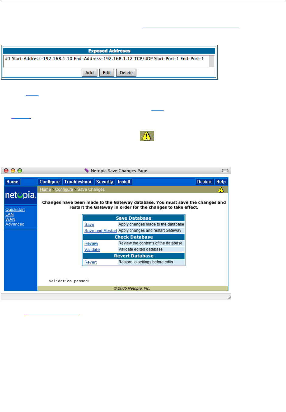
Administrator’s Handbook
156
You can add more exposed addresses by clicking the Add more Exposed Addresses link. A list of pre-
viously configured exposed addresses appears.
Click the Add button to add a new range of exposed addresses.
You can edit a previously configured range by clicking the Edit button, or delete the entry entirely by clicking
the Delete button.
All configuration changes will trigger the Alert Icon. Click on the Alert icon.
This allows you to validate the configuration and reboot the Gateway.
Click the Save and Restart link. You will be asked to confirm your choice, and the Gateway will reboot
with the new configuration.
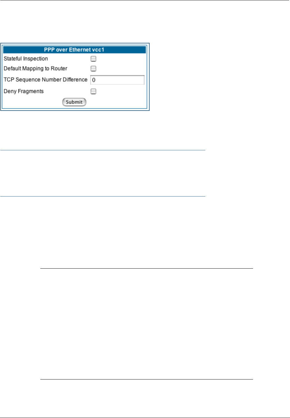
157
Stateful Inspection Options
Stateful Inspection Parameters are active on a WAN interface only if you enable them on your Gateway.
•Stateful Inspection: To enable stateful inspection on this WAN interface, check the checkbox.
•Default Mapping to Router: This is disabled by default. This option will allow the router to respond to
traffic received on this interface, for example, ICMP Echo requests.
☛ NOTE:
If Stateful Inspection is enabled on a WAN interface Default Mapping to Router must be
enabled to allow inbound VPN terminations to the router.
•TCP Sequence Number Difference: Enter a value in this field. This value represents the maximum
sequence number difference allowed between subsequent TCP packets. If this number is exceeded, the
packet is dropped. The acceptable range is 0 – 65535. A value of 0 (zero) disables this check.
•Deny Fragments: To enable this option, which causes the router to discard fragmented packets on this
interface, check the checkbox.
Open Ports in Default Stateful Inspection Installation
Port Protocol Description LAN (Private)
Interface
WAN (Public)
Interface
23 TCP telnet Yes No
53 UDP DNS Yes No
67 UDP Bootps Yes No
68 UDP Bootpc Yes No
80 TCP HTTP Yes No
137 UDP Netbios-ns Yes No
138 UDP Netbios-dgm Yes No
161 UDP SNMP Yes No
500 UDP ISAKMP Yes No
520 UDP Router Yes No

Administrator’s Handbook
158
Firewall Tutorial
General firewall terms
☛ Note:
Breakwater Basic Firewall (see “BreakWater Basic Firewall” on page 142) does not make
use of the packet filter support and can be used in addition to filtersets
Filter rule: A filter set is comprised of individual filter rules.
Filter set: A grouping of individual filter rules.
Firewall: A component or set of components that restrict access between a protected network and the
Internet, or between two networks.
Host: A workstation on the network.
Packet: Unit of communication on the Internet.
Packet filter: Packet filters allow or deny packets based on source or destination IP addresses, TCP or UDP
ports.
Port: A number that defines a particular type of service.
Basic IP packet components
All IP packets contain the same basic header information, as follows:
This header information is what the packet filter uses to make filtering decisions. It is important to note
that a packet filter does not look into the IP data stream (the User Data from above) to make filtering deci-
sions.
Basic protocol types
TCP: Transmission Control Protocol. TCP provides reliable packet delivery and has a retransmission mech-
anism (so packets are not lost). RFC 793 is the specification for TCP.
Source IP Address 163.176.132.18
Destination IP Address 163.176.4.27
Source Port 2541
Destination Port 80
Protocol TCP
DATA User Data

159
UDP: User Datagram Protocol. Unlike TCP, UDP does not guarantee reliable, sequenced packet delivery. If
data does not reach its destination, UDP does not retransmit the data. RFC 768 is the specification for
UDP.
There are many more ports defined in the Assigned Addresses RFC. The table that follows shows some of
these port assignments.
Example TCP/UDP Ports
Firewall design rules
There are two basic rules to firewall design:
•“What is not explicitly allowed is denied.”
and
•“What is not explicitly denied is allowed.”
The first rule is far more secure, and is the best approach to firewall design. It is far easier (and more
secure) to allow in or out only certain services and deny anything else. If the other rule is used, you would
have to figure out everything that you want to disallow, now and in the future.
Firewall Logic
Firewall design is a test of logic, and filter rule ordering is critical. If a packet is forwarded through a series
of filter rules and then the packet matches a rule, the appropriate action is taken. The packet will not for-
ward through the remainder of the filter rules.
For example, if you had the following filter set...
Allow WWW access;
Allow FTP access;
Allow SMTP access;
Deny all other packets.
and a packet goes through these rules destined for FTP, the packet would forward through the first rule
(WWW), go through the second rule (FTP), and match this rule; the packet is allowed through.
If you had this filter set for example....
Allow WWW access;
TCP Port Service UDP Port Service
20/21 FTP 161 SNMP
23 Telnet 69 TFTP
25 SMTP
80 WWW
144 News
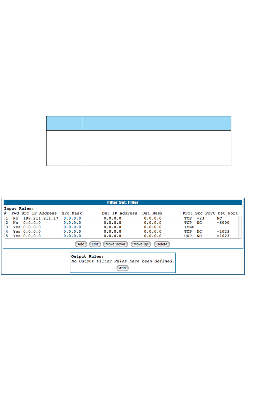
Administrator’s Handbook
160
Allow FTP access;
Deny FTP access;
Deny all other packets.
and a packet goes through these rules destined for FTP, the packet would forward through the first filter
rule (WWW), match the second rule (FTP), and the packet is allowed through. Even though the next rule is to
deny all FTP traffic, the FTP packet will never make it to this rule.
Implied rules
With a given set of filter rules, there is an Implied rule that may or may not be shown to the user. The
implied rule tells the filter set what to do with a packet that does not match any of the filter rules. An exam-
ple of implied rules is as follows:
Example filter set page
This is an example of the Motorola Netopia® filter set page:
Implied Meaning
Y+Y+Y=N If all filter rules are YES, the implied rule is NO.
N+N+N=Y If all filter rules are NO, the implied rule is YES.
Y+N+Y=N If a mix of YES and NO filters, the implied rule is NO.
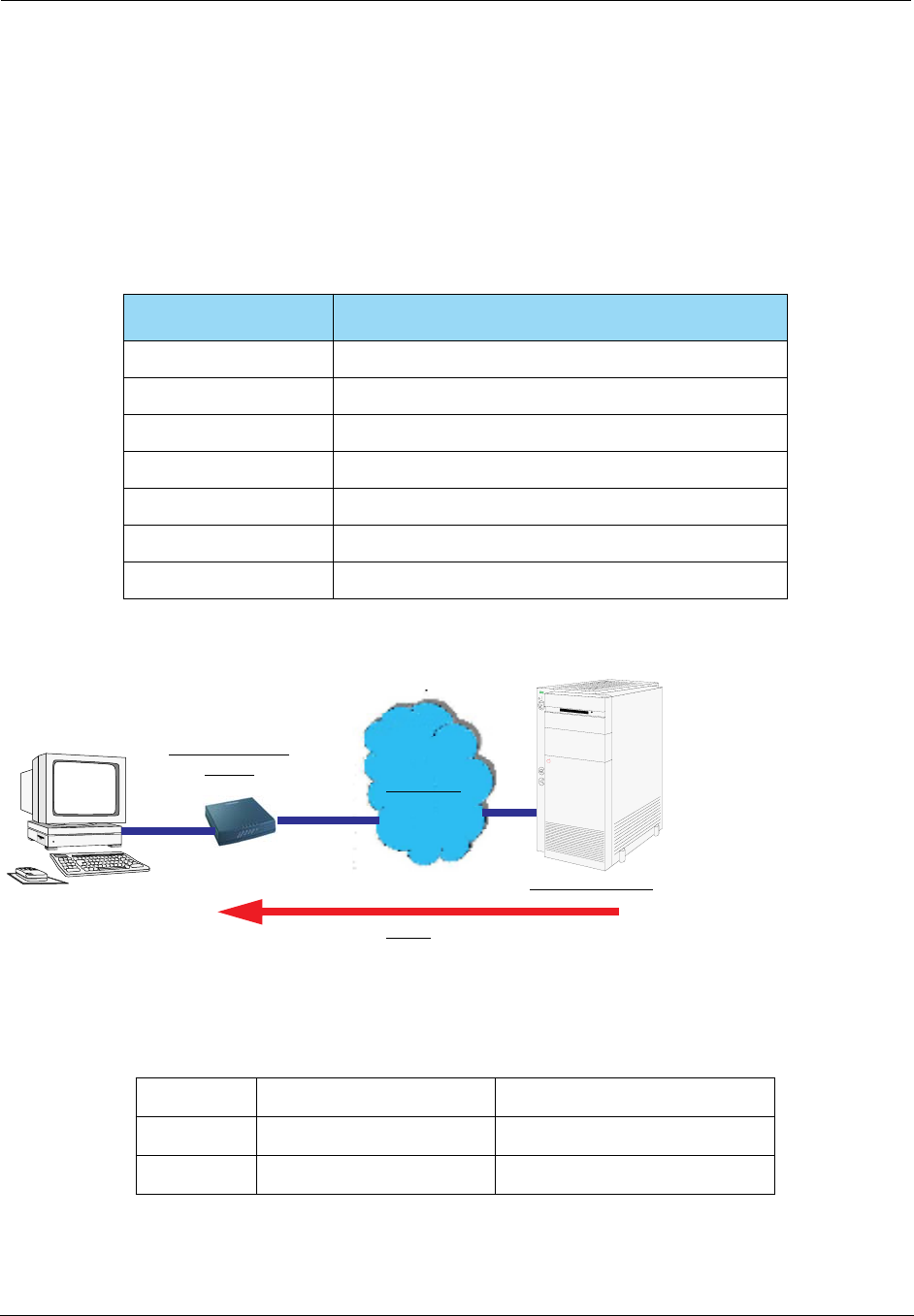
161
Filter basics
In the source or destination IP address fields, the IP address that is entered must be the network address
of the subnet. A host address can be entered, but the applied subnet mask must be 32 bits
(255.255.255.255).
Netopia Embedded Software Version 7.7.4 has the ability to compare source and destination TCP or UDP
ports. These options are as follows:
Example network
Example filters
Example 1
Incoming packet has the source address of 200.1.1.28
Item What it means
No Compare Does not compare TCP or UDP port
Not Equal To Matches any port other than what is defined
Less Than Anything less than the port defined
Less Than or Equal Any port less than or equal to the port defined
Equal Matches only the port defined
Greater Than or Equal Matches the port or any port greater
Greater Than Matches anything greater than the port defined
Filter Rule: 200.1.1.0 (Source IP Network Address)
255.255.255.128 (Source IP Mask)
Forward = No (What happens on match)
Data
Internet
IP 200.1.1.??
Input Packet
Filter

Administrator’s Handbook
162
This incoming IP packet has a source IP address that matches the network address in the Source IP
Address field in Netopia Embedded Software Version 7.7.4. This will
not
forward this packet.
Example 2
Incoming packet has the source address of 200.1.1.184.
This incoming IP packet has a source IP address that does not match the network address in the Source IP
Address field in Netopia Embedded Software Version 7.7.4. This rule
will
forward this packet because the
packet does not match.
Example 3
Incoming packet has the source address of 200.1.1.184.
This rule does
not
match and this packet will be forwarded.
Example 4
Incoming packet has the source address of 200.1.1.104.
This rule
does
match and this packet will
not
be forwarded.
Example 5
Incoming packet has the source address of 200.1.1.96.
This rule
does
match and this packet will
not
be forwarded. This rule masks off a
single
IP address.
Filter Rule: 200.1.1.0 (Source IP Network Address)
255.255.255.128 (Source IP Mask)
Forward = No (What happens on match)
Filter Rule: 200.1.1.96 (Source IP Network Address)
255.255.255.240 (Source IP Mask)
Forward = No (What happens on match)
Filter Rule: 200.1.1.96 (Source IP Network Address)
255.255.255.240 (Source IP Mask)
Forward = No (What happens on match)
Filter Rule: 200.1.1.96 (Source IP Network Address)
255.255.255.255 (Source IP Mask)
Forward = No (What happens on match)

163
Link: Packet Filter
When you click the
Packet Filter
link the
Filter Sets
screen appears.
Security should be a high priority for anyone administering a network connected to the Internet. Using
packet filters to control network communications can greatly improve your network’s security. The Packet
Filter engine allows creation of a maximum of eight Filter Sets. Each Filter Set can consist of many rules.
There can be a maximum of 32 filter rules in the system.
☛
WARNING:
Before attempting to configure filters and filter sets, please read and understand this entire
section thoroughly. Motorola Netopia® Gateways incorporating NAT have advanced security
features built in. Improperly adding filters and filter sets increases the possibility of loss of
communication with the Gateway and the Internet. Never attempt to configure filters unless you
are local to the Gateway.
Although using filter sets can enhance network security, there are disadvantages:
• Filters are complex. Combining them in filter sets introduces subtle interactions, increasing
the likelihood of implementation errors.
• Enabling a large number of filters can have a negative impact on performance. Processing of
packets will take longer if they have to go through many checkpoints in addition to NAT.
• Too much reliance on packet filters can cause too little reliance on other security methods.
Filter sets are
not
a substitute for password protection, effective safeguarding of passwords,
and general awareness of how your network may be vulnerable.
Netopia Embedded Software Version 7.7.4’s packet filters are designed to provide security for the Internet
connections made to and from your network. You can customize the Gateway’s filter sets for a variety of
packet filtering applications. Typically, you use filters to selectively admit or refuse TCP/IP connections from
certain remote networks and specific hosts. You will also use filters to screen particular types of connec-
tions. This is commonly called
firewalling
your network.
Before creating filter sets, you should read the next few sections to learn more about how these powerful
security tools work.
What’s a filter and what’s a filter set?
A filter is a rule that lets you specify what sort of data can flow in and out of your network. A particular filter
can be either an input filter—one that is used on data (packets) coming in to your network from the Inter-
net—or an output filter—one that is used on data (packets) going out from your network to the Internet.
A filter set is a group of filters that work together to check incoming or outgoing data. A filter set can consist
of a combination of input and output filters.
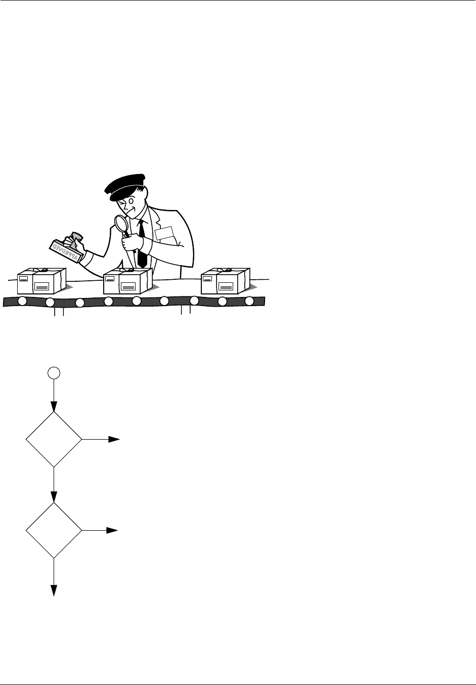
Administrator’s Handbook
164
How filter sets work
A filter set acts like a team of customs inspectors. Each filter is an inspector through which incoming and
outgoing packages must pass. The inspectors work as a team, but each inspects every package individu-
ally.
Each inspector has a specific task. One inspector’s task may be to examine the destination address of all
outgoing packages. That inspector looks for a certain destination—which could be as specific as a street
address or as broad as an entire country—and checks each package’s destination address to see if it
matches that destination.
A filter inspects data packets like a customs inspector scrutinizing packages.
Filter priority
Continuing the customs inspectors analogy, imagine the inspectors lined up
to examine a package. If the package matches the first inspector’s criteria,
the package is either rejected or passed on to its destination, depending on
the first inspector’s particular orders. In this case, the package is never
seen by the remaining inspectors.
If the package does not match the first inspector’s criteria, it goes to the
second inspector, and so on. You can see that the order of the inspectors in
the line is very important.
For example, let’s say the first inspector’s orders are to send along all pack-
ages that come from Rome, and the second inspector’s orders are to reject
all packages that come from France. If a package arrives from Rome, the
first inspector sends it along without allowing the second inspector to see it.
A package from Paris is ignored by the first inspector, rejected by the second
inspector, and never seen by the others. A package from London is ignored
by the first two inspectors, so it’s seen by the third inspector.
In the same way, filter sets apply their filters in a particular order. The first fil-
ter applied can forward or discard a packet before that packet ever reaches
any of the other filters. If the first filter can neither forward nor discard the
packet (because it cannot match any criteria), the second filter has a chance
to forward or reject it, and so on. Because of this hierarchical structure,
each filter is said to have a priority. The first filter has the highest priority, and the last filter has the lowest
priority.
INSPECTOR
FROM:
TO:
FROM:
TO:
FROM:
TO:
APPROVED
packet
first
filter
match?
yes
forward
discard?
to network
discard
(delete)
forward
no
to next
filter
send
or
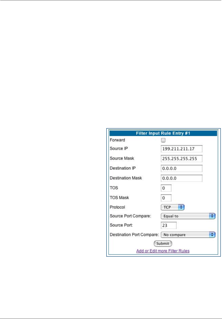
165
How individual filters work
As described above, a filter applies criteria to an IP packet and then takes one of three actions:
•
Forwards the packet to the local or remote network
•
Blocks (discards) the packet
•
Ignores the packet
A filter forwards or blocks a packet only if it finds a match after applying its criteria. When no match occurs,
the filter ignores the packet.
A filtering rule
The criteria are based on information contained in the packets. A filter is simply a rule that prescribes cer-
tain actions based on certain conditions. For example, the following rule qualifies as a filter:
“Block all Telnet attempts that originate from the remote host 199.211.211.17.”
This rule applies to Telnet packets that come from a host with the IP address 199.211.211.17. If a match
occurs, the packet is blocked.
Here is what this rule looks like when imple-
mented as a filter in Netopia Embedded Software
Version 7.7.4:
To understand this particular filter, look at the
parts of a filter.
Parts of a filter
A filter consists of criteria based on packet
attributes. A typical filter can match a packet on
any one of the following attributes:
•
The source IP address and subnet mask
(where the packet was sent from)
•
The destination IP address and subnet mask
(where the packet is going)
•
The TOS bit setting of the packet. Certain
types of IP packets, such as voice or multime-
dia packets, are sensitive to delays introduced
by the network. A delay-sensitive packet is
identified by a special low-latency setting called
the TOS bit. It is important for such packets to
be received rapidly or the quality of service
degrades.
•
The type of higher-layer Internet protocol the packet is carrying, such as TCP or UDP
Port numbers
A filter can also match a packet’s port number attributes, but only if the filter’s protocol type is set to TCP
or UDP, since only those protocols use port numbers. The filter can be configured to match the following:
•
The source port number (the port on the sending host that originated the packet)
•
The destination port number (the port on the receiving host that the packet is destined for)
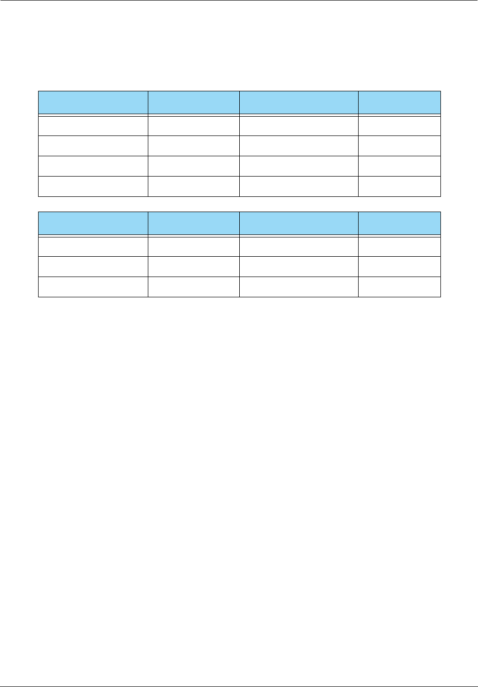
Administrator’s Handbook
166
By matching on a port number, a filter can be applied to selected TCP or UDP services, such as Telnet, FTP,
and World Wide Web. The following tables show a few common services and their associated port numbers:
Port number comparisons
A filter can also use a comparison option to evaluate a packet’s source or destination port number. The
comparison options are:
•
No Compare:
No comparison of the port number specified in the filter with the packet’s port number.
•
Not Equal To:
For the filter to match, the packet’s port number cannot equal the port number specified
in the filter.
•
Less Than:
For the filter to match, the packet’s port number must be less than the port number speci-
fied in the filter.
•
Less Than or Equal:
For the filter to match, the packet’s port number must be less than or equal to the
port number specified in the filter.
•
Equal:
For the filter to match, the packet’s port number must equal the port number specified in the fil-
ter.
•
Greater Than:
For the filter to match, the packet’s port number must be greater than the port number
specified in the filter.
•
Greater Than or Equal:
For the filter to match, the packet’s port number must be greater than or equal
to the port number specified in the filter.
Other filter attributes
There are three other attributes to each filter:
•The filter’s order (i.e., priority) in the filter set
•Whether the filter is currently active
•Whether the filter is set to forward packets or to block (discard) packets
Internet service TCP port Internet service TCP port
FTP 20/21 Finger 79
Telnet 23 World Wide Web 80
SMTP (mail) 25 News 144
Gopher 70 rlogin 513
Internet service UDP port Internet service UDP port
Who Is 43 TFTP 69
World Wide Web 80 who 513
SNMP 161
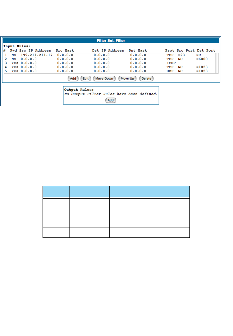
167
Putting the parts together
When you display a filter set, its filters are displayed as rows in a table:
The table’s columns correspond to each filter’s attributes:
•#: The filter’s priority in the set. Filter number 1, with the highest priority, is first in the table.
•Fwd: Shows whether the filter forwards (Yes) a packet or discards (No) it when there’s a match.
•Src-IP: The packet source IP address to match.
•Src-Mask: The packet source subnet mask to match.
•Dst-IP: The packet destination IP address to match.
•Dst-Mask: The packet destination IP address to match.
•Protocol: The protocol to match. This can be entered as a number (see the table below) or as TCP or
UDP if those protocols are used.
•Src Port: The source port to match. This is the port on the sending host that originated the packet.
•Dst Port: The destination port to match. This is the port on the receiving host for which the packet is
intended.
•NC: Indicates No Compare, where specified.
Filtering example #1
Returning to our filtering rule example from above (see page 165), look at how a rule is translated into a fil-
ter. Start with the rule, then fill in the filter’s attributes:
•The rule you want to implement as a filter is:
“Block all Telnet attempts that originate from the remote host 199.211.211.17.”
Protocol Number to use Full name
N/A 0 Ignores protocol type
ICMP 1 Internet Control Message Protocol
TCP 6 Transmission Control Protocol
UDP 17 User Datagram Protocol
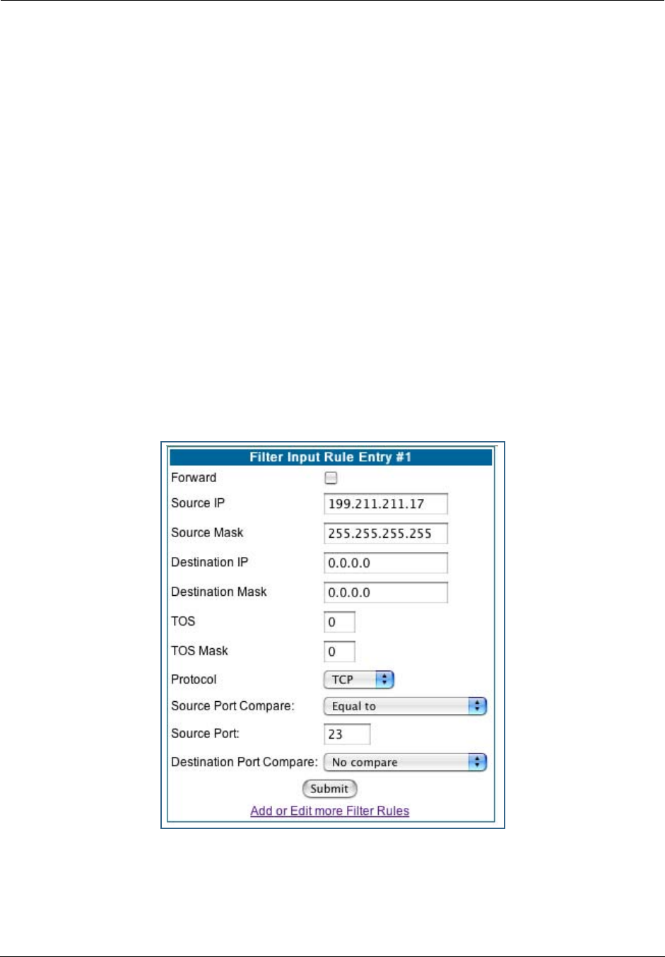
Administrator’s Handbook
168
•The host 199.211.211.17 is the source of the Telnet packets you want to block, while the destination
address is any IP address. How these IP addresses are masked determines what the final match will be,
although the mask is not displayed in the table that displays the filter sets (you set it when you create
the filter). In fact, since the mask for the destination IP address is 0.0.0.0, the address for Destination
IP address could have been anything. The mask for Source IP address must be 255.255.255.255 since
an exact match is desired.
• Source IP Address = 199.211.211.17
• Source IP address mask = 255.255.255.255
• Destination IP Address = 0.0.0.0
• Destination IP address mask = 0.0.0.0
•Using the tables on page 166, find the destination port and protocol numbers (the local Telnet port):
• Protocol = TCP (or 6)
• Destination Port = 23
•The filter should be enabled and instructed to block the Telnet packets containing the source address
shown in step 2:
• Forward = unchecked
This four-step process is how we produced the following filter from the original rule:
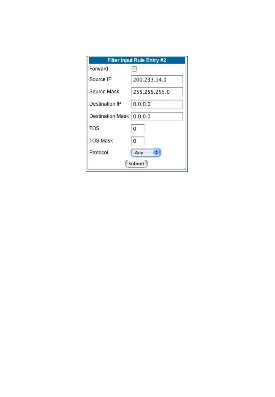
169
Filtering example #2
Suppose a filter is configured to block all incoming IP packets with the source IP address of 200.233.14.0,
regardless of the type of connection or its destination. The filter would look like this:
This filter blocks any packets coming from a remote network with the IP network address 200.233.14.0.
The 0 at the end of the address signifies any host on the class C IP network 200.233.14.0. If, for example,
the filter is applied to a packet with the source IP address 200.233.14.5, it will block it.
In this case, the mask, must be set to 255.255.255.0. This way, all packets with a source address of
200.233.14.x will be matched correctly, no matter what the final address byte is.
☛ Note:
The protocol attribute for this filter is Any by default. This tells the filter to ignore the IP protocol
or type of IP packet.
Design guidelines
Careful thought must go into designing a new filter set. You should consider the following guidelines:
•Be sure the filter set’s overall purpose is clear from the beginning. A vague purpose can lead to a faulty
set, and that can actually make your network less secure.
•Be sure each individual filter’s purpose is clear.
•Determine how filter priority will affect the set’s actions. Test the set (on paper) by determining how the
filters would respond to a number of different hypothetical packets.
•Consider the combined effect of the filters. If every filter in a set fails to match on a particular packet,
the packet is:
• Forwarded if all the filters are configured to discard (not forward)
• Discarded if all the filters are configured to forward
• Discarded if the set contains a combination of forward and discard filters

Administrator’s Handbook
170
An approach to using filters
The ultimate goal of network security is to prevent unauthorized access to the network without compromis-
ing authorized access. Using filter sets is part of reaching that goal.
Each filter set you design will be based on one of the following approaches:
•That which is not expressly prohibited is permitted.
•That which is not expressly permitted is prohibited.
It is strongly recommended that you take the latter, and safer, approach to all of your filter set designs.
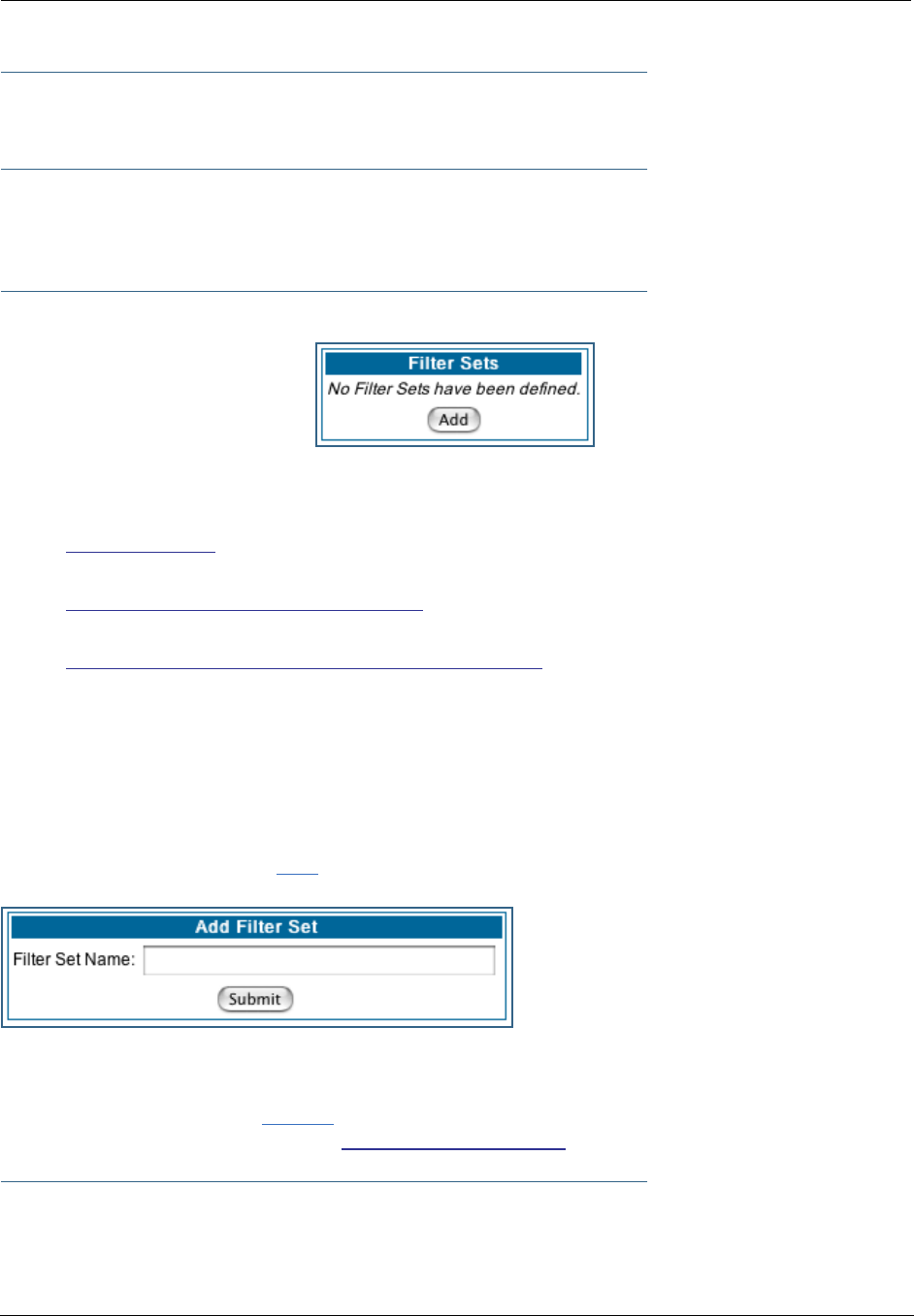
171
Working with IP Filters and Filter Sets
To work with filters and filter sets, begin by accessing the filter set pages.
☛ NOTE:
Make sure you understand how filters work before attempting to use them. Read the section
“Packet Filter” on page 163.
The procedure for creating and maintaining filter sets is as follows:
1. Add a new filter set.
See Adding a filter set, below.
2. Create the filters for the new filter set.
See “Adding filters to a filter set” on page 172.
3. Associate the filter set with either the LAN or WAN interface.
See “Associating a Filter Set with an Interface” on page 176.
The sections below explain how to execute these steps.
Adding a filter set
You can create up to eight different custom filter sets. Each filter set can contain up to 16 output filters and
up to 16 input filters. There can be a maximum of 32 filter rules in the system.
To add a new filter set, click the Add button in the Filter Sets page. The Add Filter Set page appears.
Enter new name for the filter set, for example Filter Set 1.
To save the filter set, click the Submit button. The saved filter set is empty (contains no filters), but you
can return to it later to add filters (see “Adding filters to a filter set”).
☛ NOTE:
As you begin to build a filter set, and as you add filters, after your first entry, the Alert icon
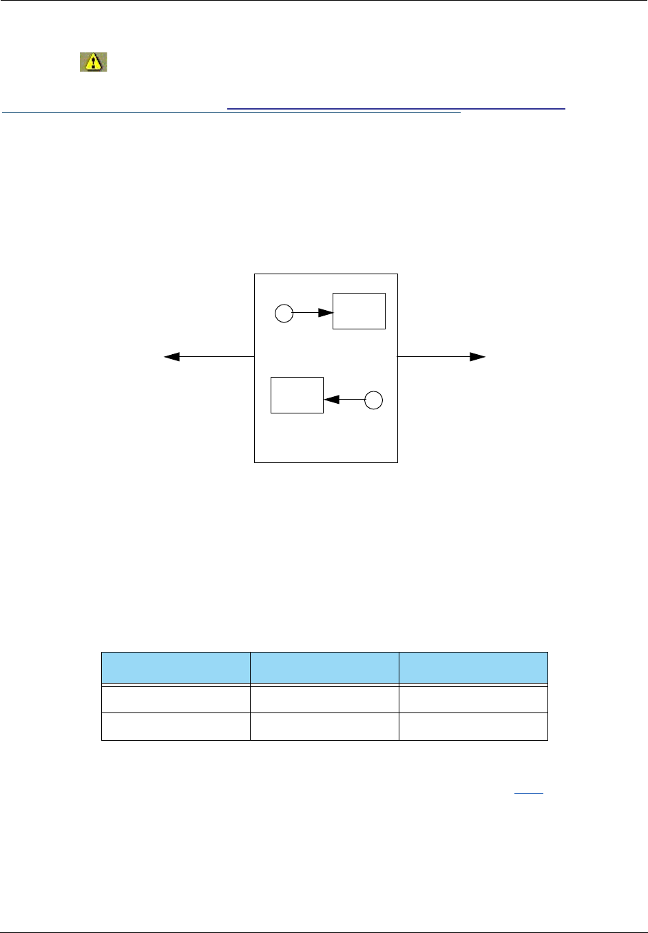
Administrator’s Handbook
172
will appear in the upper right corner of the web page. It will remain until all of your
changes are entered and validated. You need not immediately restart the Gateway until your fil-
ter set is complete. See “Associating a Filter Set with an Interface” on page 176.
Adding filters to a filter set
There are two kinds of filters you can add to a filter set: input and output. Input filters check packets
received from the Internet, destined for your network. Output filters check packets transmitted from your
network to the Internet.
Packets in Netopia Embedded Software Version 7.7.4 pass through an input filter if they originate from the WAN and
through an output filter if they’re being sent out to the WAN.
The process for adding input and output filters is exactly the same. The main difference between the two
involves their reference to source and destination. From the perspective of an input filter, your local network
is the destination of the packets it checks, and the remote network is their source. From the perspective of
an output filter, your local network is the source of the packets, and the remote network is their destination.
To add a filter, select the Filter Set Name to which you will add a filter, and click the Edit button.
Type of filter Source means Destination means
Input filter The remote network The local network
Output filter The local network The remote network
The Motorola Netopia® Router
input filter
output filter
LAN
WAN
packet
packet
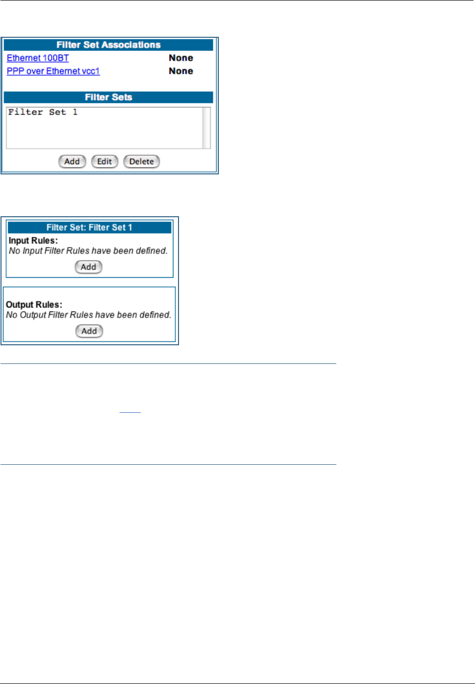
173
The Filter Set page appears.
☛ Note:
There are two Add buttons in this page, one for input filters and one for output filters. In this
section, you’ll learn how to add an input filter to a filter set. Adding an output filter works
exactly the same way, providing you keep the different source and destination perspectives in
mind.
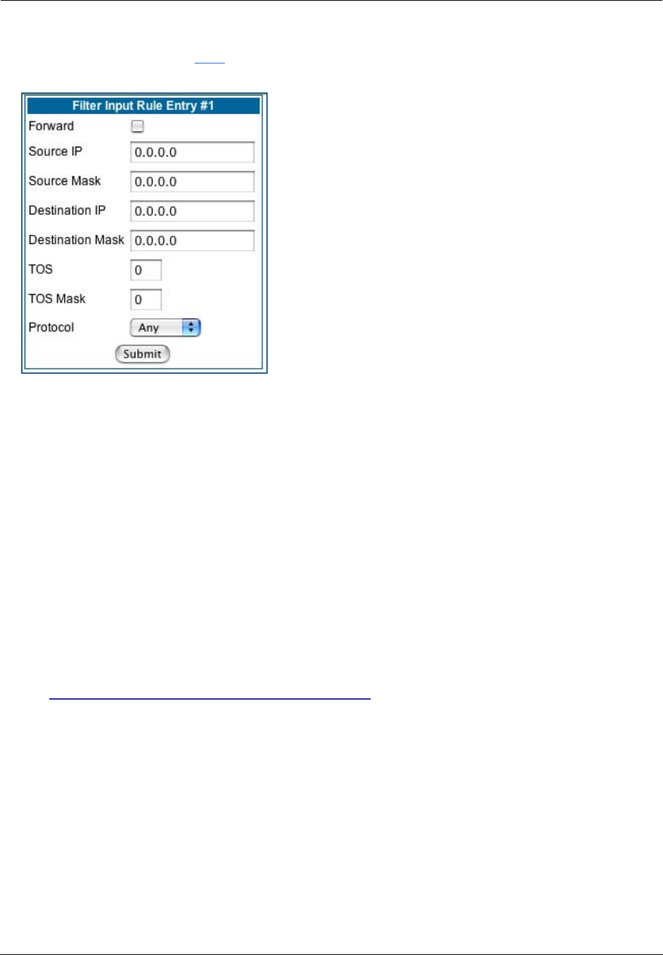
Administrator’s Handbook
174
1. To add a filter, click the Add button under Input Rules.
The Input Rule Entry page appears.
2. If you want the filter to forward packets that match its criteria to the destination IP
address, check the
Forward
checkbox.
If Forward is unchecked, packets matching the filter’s criteria will be discarded.
3. Enter the
Source IP
address this filter will match on.
You can enter a subnet or a host address.
4. Enter the
Source Mask
for the source IP address.
This allows you to further modify the way the filter will match on the source address. Enter 0.0.0.0 to
force the filter to match on all source IP addresses, or enter 255.255.255.255 to match the source IP
address exclusively.
5. Enter the
Destination IP
Address this filter will match on.
You can enter a subnet or a host address.
6. Enter the
Destination Mask
for the destination IP address.
This allows you to further modify the way the filter will match on the destination address. Enter 0.0.0.0
to force the filter to match on all destination IP addresses.
7. If desired, you can enter a TOS and TOS Mask value.
See “Policy-based Routing using Filtersets” on page 177 for more information.
8. Select
Protocol
from the pull-down menu: ICMP, TCP, UDP, Any, or the number of
another IP transport protocol (see the table on page 167).
If Protocol Type is set to TCP or UDP, the settings for port comparison will appear. These settings only
take effect if the Protocol Type is TCP or UDP.
9. From the
Source Port Compare
pull-down menu, choose a comparison method for the
filter to use on a packet’s source port number.
Then select
Source Port
and enter the actual source port number to match on (see the table on
page 166).
10. From the Destination Port Compare pull-down menu, choose a comparison method for
the filter to use on a packet’s destination port number.
Then select
Destination Port
and enter the actual destination port number to match on (see the table
on page 166).
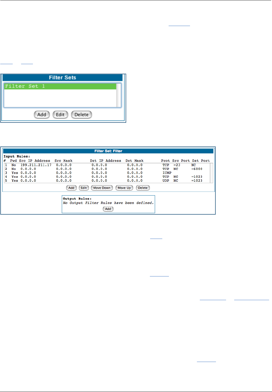
175
11. When you are finished configuring the filter, click the Submit button to save the filter in
the filter set.
Viewing filters
To display the table of input or output filters, select the Filter Set Name in the Filter Set page and click the
Add or Edit button.
The table of filters in the filtersets appears.
Modifying filters
To modify a filter, select a filter from the table and click the Edit button. The Rule Entry page appears. The
parameters in this page are set in the same way as the ones in the original Rule Entry page (see “Adding fil-
ters to a filter set” on page 172).
Deleting filters
To delete a filter, select a filter from the table and click the Delete button.
Moving filters
To reorganize the filters in a filter set, select a filter from the table and click the Move Up or Move Down
button to place the filter in the desired priority position.
Deleting a filter set
If you delete a filter set, all of the filters it contains are deleted as well. To reuse any of these filters in
another set, before deleting the current filter set you’ll have to note their configuration and then recreate
them.
To delete a filter set, select the filter set from the Filter Sets list and click the Delete button.
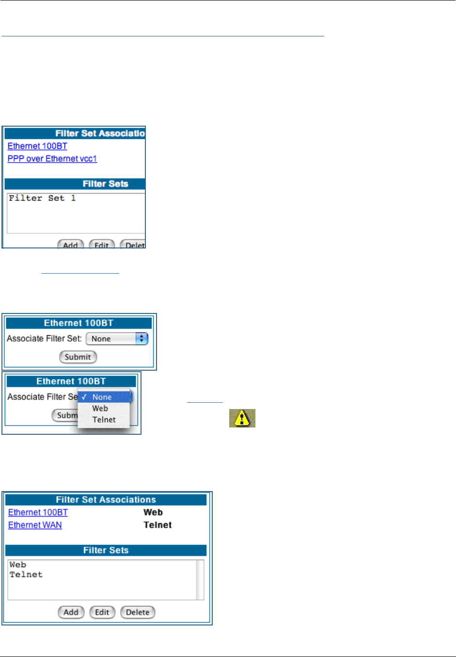
Administrator’s Handbook
176
Associating a Filter Set with an Interface
Once you have created a filter set, you must associate it with an interface in order for it to be effective.
Depending on its application, you can associate it with either the WAN (usually the Internet) interface or the
LAN.
To associate an filter set with the LAN, return to the Filter Sets page.
Click the Ethernet 100BT link.
The Ethernet 100BT page appears.
From the pull-down menu, select the filter set to associate with this
interface.
Click the Submit button. The Alert icon will appear in the upper right
corner of the page.
Click the Alert icon to go to the validation page, where you can save your configuration.
You can repeat this process for both the WAN and LAN interfaces, to associate your filter sets.
When you return to the Filter Sets page, it will display
your interface associations.
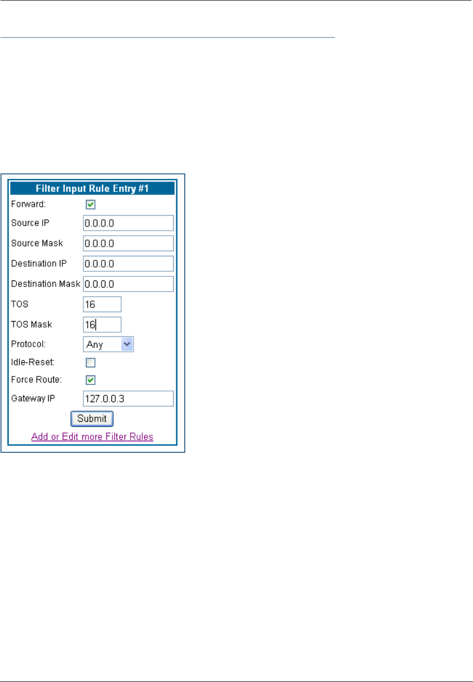
177
Policy-based Routing using Filtersets
Netopia Embedded Software Version 7.7.4 offers the ability to route IP packets using criteria other than the
destination IP address. This is called policy-based routing.
You specify the routing criteria and routing information by using IP filtersets to determine the forwarding
action of a particular filter.
You specify a gateway IP address, and each packet matching the filter is routed according to that gateway
address, rather than by means of the global routing table.
In addition, the classifier list in a filter includes the TOS field. This allows you to filter on TOS field settings
in the IP packet, if you want.
To use the policy-based routing feature, you create a filter that
forwards the traffic.
•Check the Forward checkbox. This will display the Force Rout-
ing options.
•Check the Force Route checkbox.
•Enter the Gateway IP address in standard dotted-quad nota-
tion to which the traffic should be forwarded.
•You can enter Source and Destination IP Address(es) and
Mask(s), Protocol Type, and Source and Destination Port
ID(s) for the filter, if desired.
TOS field matching
Netopia Embedded Software Version 7.7.4 includes two
parameters for an IP filter: TOS and TOS Mask. Both fields
accept values in the range 0 – 255.
Certain types of IP packets, such as voice or multimedia
packets, are sensitive to latency introduced by the network. A
delay-sensitive packet is one that has the low-latency bit set in
the TOS field of the IP header. This means that if such packets
are not received rapidly, the quality of service degrades. If you
expect to route significant amounts of such traffic you can
configure your router to route this type of traffic to a gateway
other than your normal gateway using this feature.
The TOS field matching check is consistent with source and destination address matching.
If you check the Idle Reset checkbox, a match on this rule will keep the WAN connection alive by resetting
the idle-timeout status.
The Idle Reset setting is used to determine if a packet which matches the filter will cause an “instant-on”
link to connect, if it is down; or reset its idle timer, if it is already up. For example, if you wanted ping traffic
not to keep the link up, you would create a filter which forwards a ping, but with the Idle Reset checkbox
unchecked.
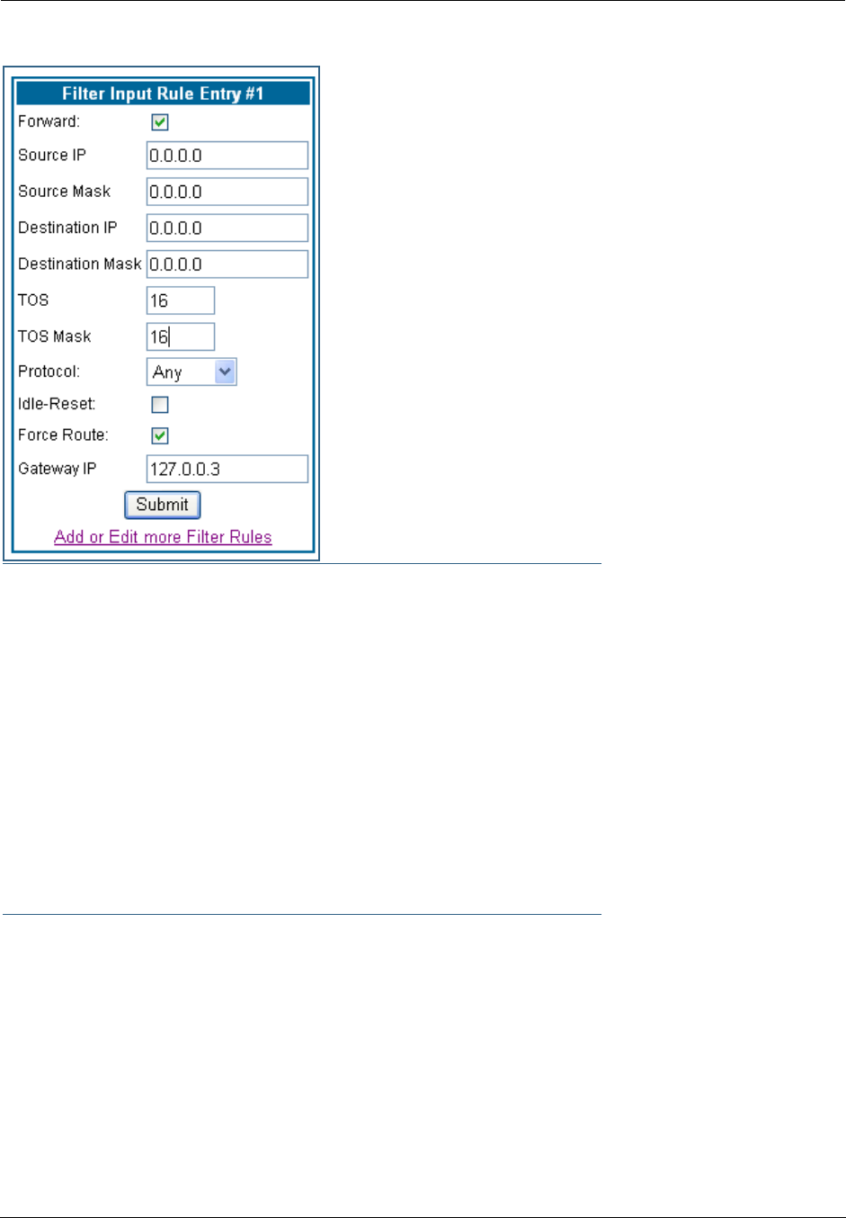
Administrator’s Handbook
178
Example: You want packets with the TOS low latency bit to go
through VC 2 (via gateway 127.0.0.3 – the Motorola Netopia®
Gateway will use 127.0.0.x, where x is the WAN port + 1) instead
of your normal gateway.
You would set up the filter as shown here.
☛ NOTE:
Default Forwarding Filter
If you create one or more filters that have a matching action of forward, then action on a
packet matching none of the filters is to block any traffic.
Therefore, if the behavior you want is to force the routing of a certain type of packet and pass
all others through the normal routing mechanism, you must configure one filter to match the
first type of packet and apply Force Routing. A subsequent filter is required to match and for-
ward all other packets.
Management IP traffic
If the Force Routing filter is applied to source IP addresses, it may inadvertently block commu-
nication with the router itself. You can avoid this by preceding the Force Routing filter with a fil-
ter that matches the destination IP address of the Gateway itself.

179
Link: Security Log
Security Monitoring is a keyed feature. See page 187 for information concerning installing Motorola Neto-
pia® Software Feature Keys.
Security Monitoring detects security-related events, including common types of malicious attacks, and
writes them to the security log file.
Using the Security Monitoring Log
You can view the Security Log at any time. Use the following steps:
1. Click the Security
toolbar button.
2. Click the Security Log link.
3. Click the Show link from the Security Log tool bar.
4. An example of the Security Log is shown on the next page.
5. When a new security event is detected, you will see the Alert button.
The Security Alert remains until you view the information. Clicking the Alert button will take you directly
to a page showing the log.

Administrator’s Handbook
180
The capacity of the security log is 100 security alert messages. When the log reaches capacity, subsequent
messages are not captured, but they are noted in the log entry count.
To reset this log, select Reset from the Security Monitor tool bar.
The following message is displayed.
Your Netopia Gateway has detected and successfully blocked an event that could have
compromised the security of your network.
Please refer to your customer documentation for a description of the logged event.
Number of security log entries : 5
Security alert type : Port Scan
Protocol type : TCP
IP source address : 143.137.137.14
Time at last attempt : Fri May 21 15:17:40 2004 (UTC)
Number of ports that were scanned : 9
Highest port : 1167
Lowest port : 1094
1102 1108 1094 1099 1166 1167 1151 1160 1164
Security alert type : Excessive Pings
IP source address : 143.137.137.92
IP destination address : 143.137.199.8
Number of attempts : 90
Time at last attempt : Fri May 21 17:52:22 2004 (UTC)
Security alert type : Port Scan
Protocol type : TCP
IP source address : 143.137.50.2
Time at last attempt : Fri May 21 17:51:37 2004 (UTC)
Number of ports that were scanned : 241
Highest port : 5302
Lowest port : 73
111 473 602 863 817 1994 805 395 5302 1670
(Only the first 10 ports are recorded.)
Security alert type : Port Scan
Protocol type : UDP
IP source address : 143.137.50.2
Time at last attempt : Fri May 21 17:52:43 2004 (UTC)
Number of ports that were scanned : 162
Highest port : 5236
Lowest port : 1
583 1 1471 444 4133 811 5236 650 776 1492
(Only the first 10 ports are recorded.)
Security alert type : Illegal Packet Size (Ping of Death)
IP source address : 192.168.1.3
IP destination address : 143.137.199.8
Number of attempts : 5
Time at last attempt : Fri May 21 18:05:33 2004 (UTC)
Illegal packet size : 65740
The security log has been reset.

181
When the Security Log contains no entries, this is the response:
Timestamp Background
During bootup, to provide better log information and to support improved troubleshooting, a Motorola Neto-
pia® Gateway acquires the National Institute of Standards and Technology (NIST) Universal Coordinated
Time (UTC) reference signal, and then adjusts it for your local time zone.
Once per hour, the Gateway attempts to re-acquire the NIST reference, for re-synchronization or initial acqui-
sition of the UTC information. Once acquired, all subsequent log entries display this date and time informa-
tion. UTC provides the equivalent of Greenwich Mean Time (GMT) information.
If the WAN connection is not enabled (or NTP has been disabled), the internal clocking function of the Gate-
way provides log timestamps based on “uptime” of the unit.
The security log is empty.
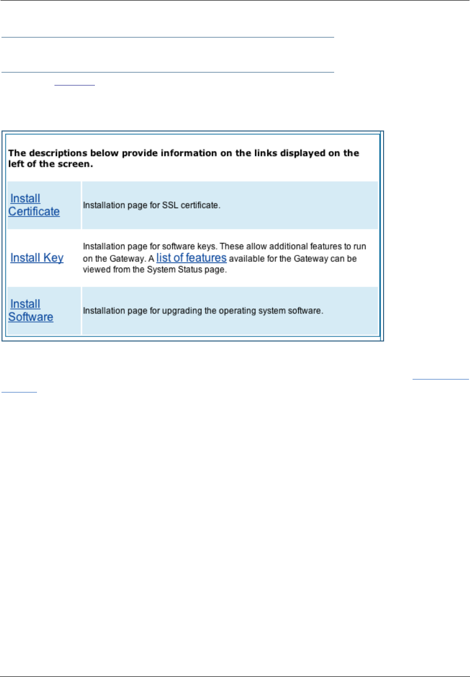
Administrator’s Handbook
182
Install
Button: Install
From the Install toolbar button you can Install new Operating System Software and Feature Keys as
updates become available.
On selected models, you can install a Secure Sockets Layer (SSL V3.0) certificate from a trusted Certifica-
tion Authority (CA) for authentication purposes. If this feature is available on your Gateway, the Install Cer-
tificate link will appear in the Install page as shown. Otherwise, it will not appear.
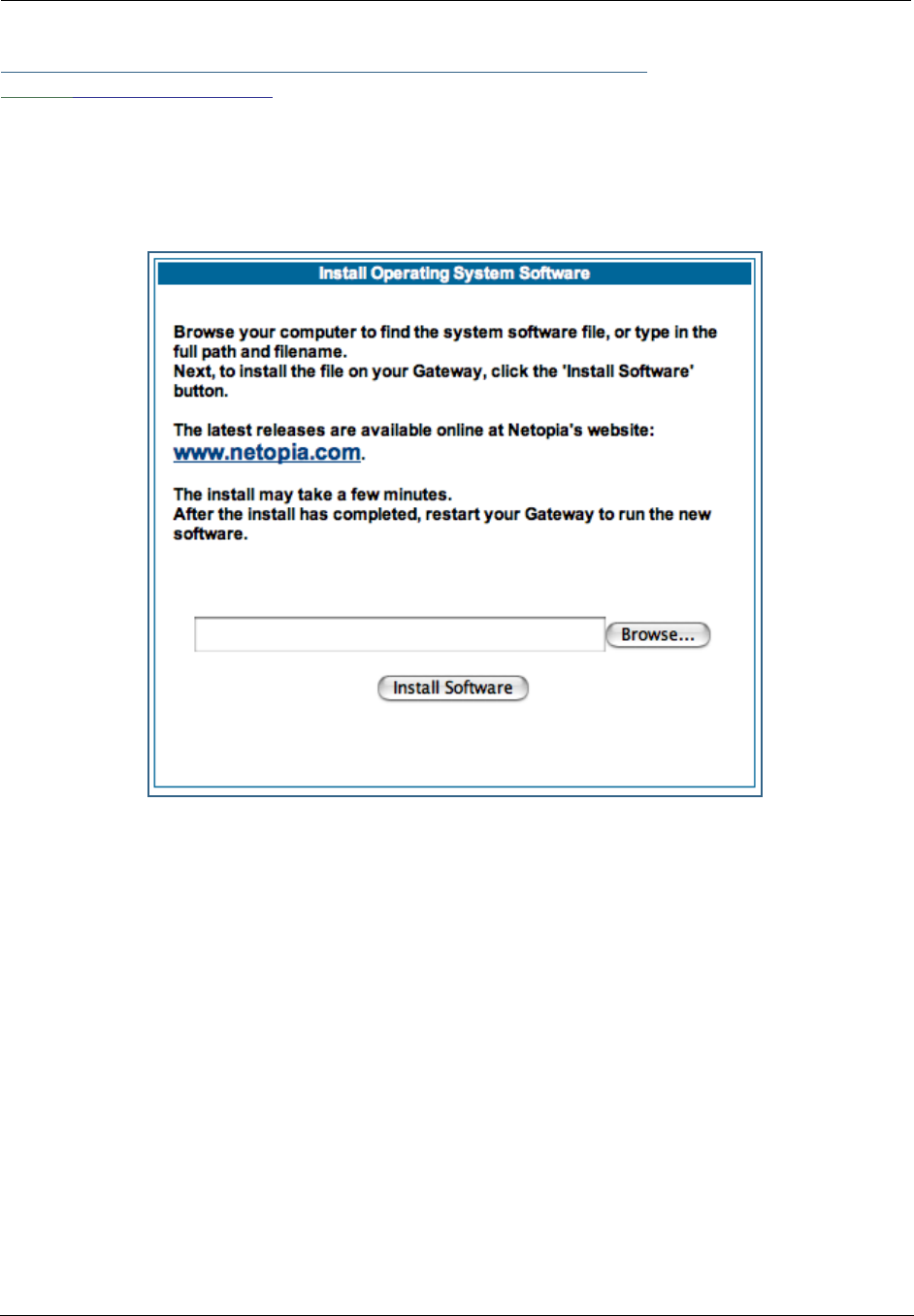
183
Link: Install Software
(This link is not available on the 3342/3352 models, since firmware updates must be upgraded via the
USB host driver. 3342N/3352N models are upgradeable by this procedsure.)
This page allows you to install an updated release of the Motorola Netopia® Firmware.
Updating Your Gateway’s Motorola Netopia® Firmware Version. You install a new operat-
ing system image in your unit from the Install Operating System Software page. For this process, the com-
puter you are using to connect to the Motorola Netopia® Gateway must be on the same local area network
as the Motorola Netopia® Gateway.
Step 1: Required Files
Upgrading Netopia Embedded Software Version 7.7.4 requires a Motorola Netopia® firmware image file.
Background
Firmware upgrade image files are posted periodically on the Motorola Netopia® website. You can download
the latest operating system software for your Gateway by accessing the following URL:
http://www.netopia.com/support/hardware/
Be sure to download the correct file for your particular Gateway. Different Gateway models have different
firmware files. Also, be sure your ISP supports the version of firmware you want to use.

Administrator’s Handbook
184
When you download your firmware upgrade from the Motorola Netopia® website, be sure to download the
latest User Guide PDF files. These are also posted on the Motorola Netopia® website in the Documentation
Center.
Confirm Motorola Netopia® Firmware Image Files
The Motorola Netopia® firmware Image file is specific to the model and the product identification number.
1. Confirm that you have received the appropriate Motorola Netopia® Firmware Image file.
2. Save the Motorola Netopia® Firmware image file to a convenient location on your PC.
Step 2: Motorola Netopia® firmware Image File
Install the Motorola Netopia® firmware Image
To install the Motorola Netopia® firmware in your Motorola Netopia® Gateway from the Home Page use
the following steps:
1. Open a web connection to your Motorola Netopia® Gateway from the computer on your
LAN.
2. Click the Install Software button on the Motorola Netopia® Gateway
Home
page.
The Install Operating System Software window opens.
3. Enter the filename into the text box by using one of these techniques:
The Motorola Netopia® firmware file name begins with a shortened form of the version number and
ends with the suffix “.bin” (for “binary”). Example: nta760.bin
a. Click the Browse button, select the file you want, and click Open.
-or-
b. Enter the name and path of the software image you want to install in the text field.
4. Click the Install Software button.
The Motorola Netopia® Gateway copies the image file from your computer and installs it into its memory
storage. You see a progress bar appear on your screen as the image is copied and installed.
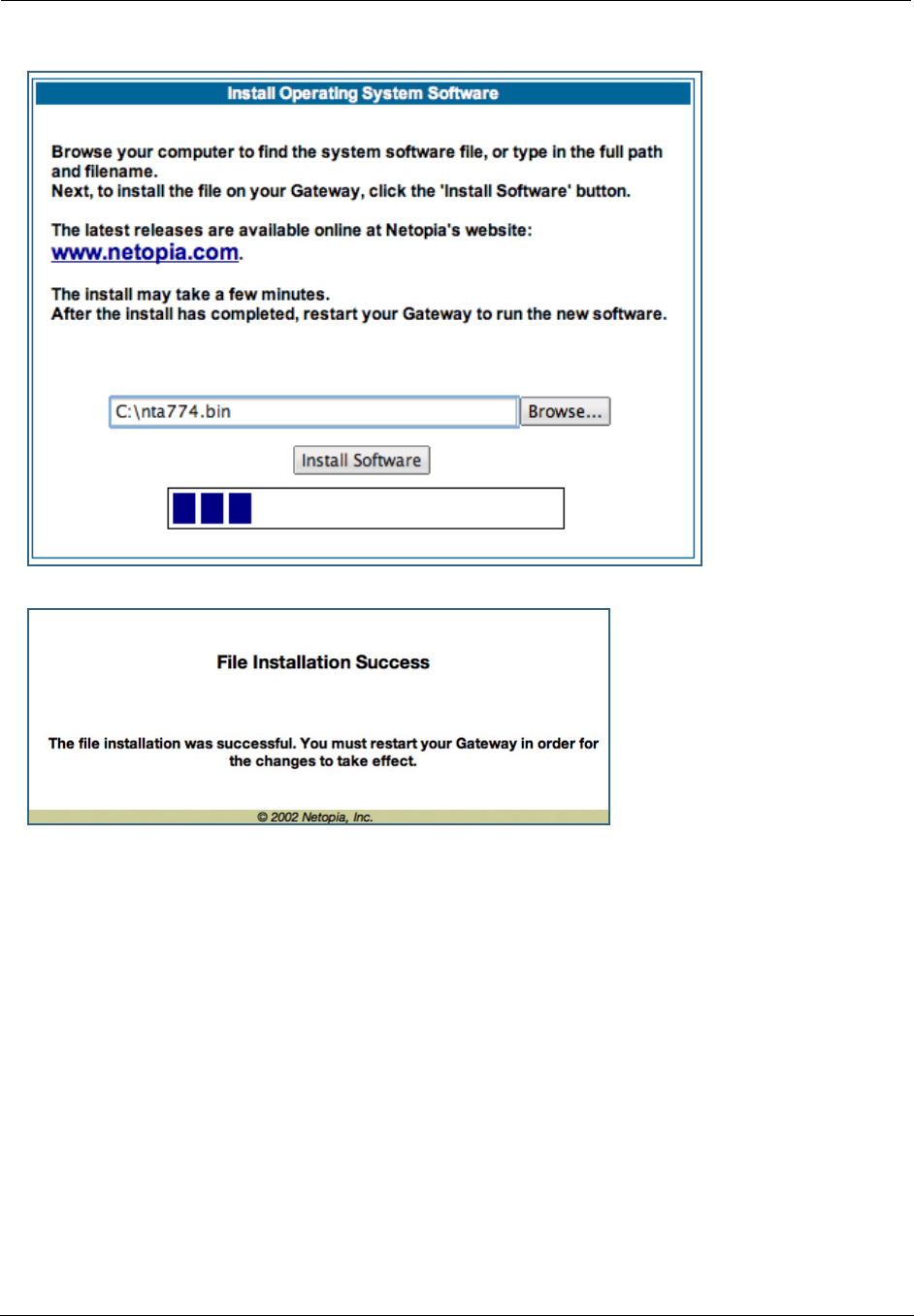
185
When the image has been installed, a success message displays.
5. When the success message appears, click the Restart button and confirm the Restart
when you are prompted.
Your Motorola Netopia® Gateway restarts with its new image.
Verify the Motorola Netopia® Firmware Release
To verify that the Motorola Netopia® firmware image has loaded successfully, use the following steps:
1. Open a web connection to your Motorola Netopia® Gateway from the computer on your
LAN and return to the Home page.
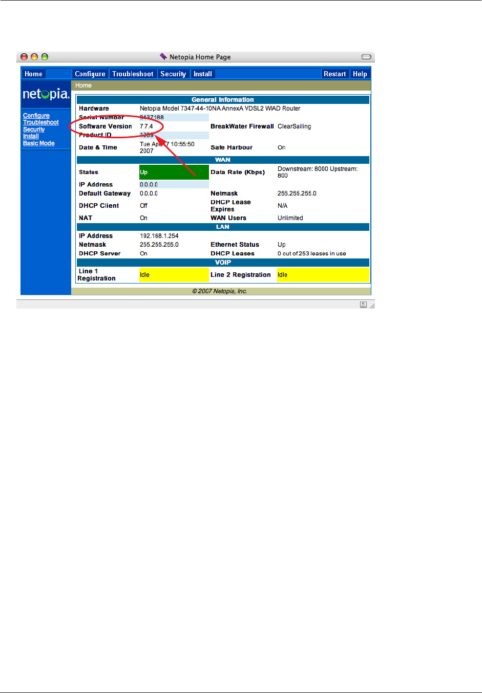
Administrator’s Handbook
186
2. Verify your Motorola Netopia® firmware release, as shown on the Home Page.
This completes the upgrade process.

187
Link: Install Key
You can obtain advanced product functionality by employing a software Feature Key. Software feature keys
are specific to a Gateway's serial number. Once the feature key is installed and the Gateway is restarted,
the new feature's functionality becomes enabled.
Use Motorola Netopia® Software Feature Keys
Motorola Netopia® Gateway users obtain advanced product functionality by installing a software feature
key. This concept utilizes a specially constructed and distributed keycode (referred to as a feature key) to
enable additional capability within the unit.
Software feature key properties are specific to a unit’s serial number; they will not be accepted on a plat-
form with another serial number.
Once installed, and the Gateway restarted, the new feature’s functionality becomes available. This allows
full access to configuration, operation, maintenance and administration of the new enhancement.
Obtaining Software Feature Keys
Contact Motorola or your Service Provider to acquire a Software Feature Key.
Procedure - Install a New Feature Key File
With the appropriate feature keycode, use the steps listed below to enable a new function.
1. From the Home page, click the Install toolbar button.
2. Click Install Keys
The Install Key File page appears.
3. Enter the feature keycode in the input Text Box.
Type the full keycode in the Text Box.
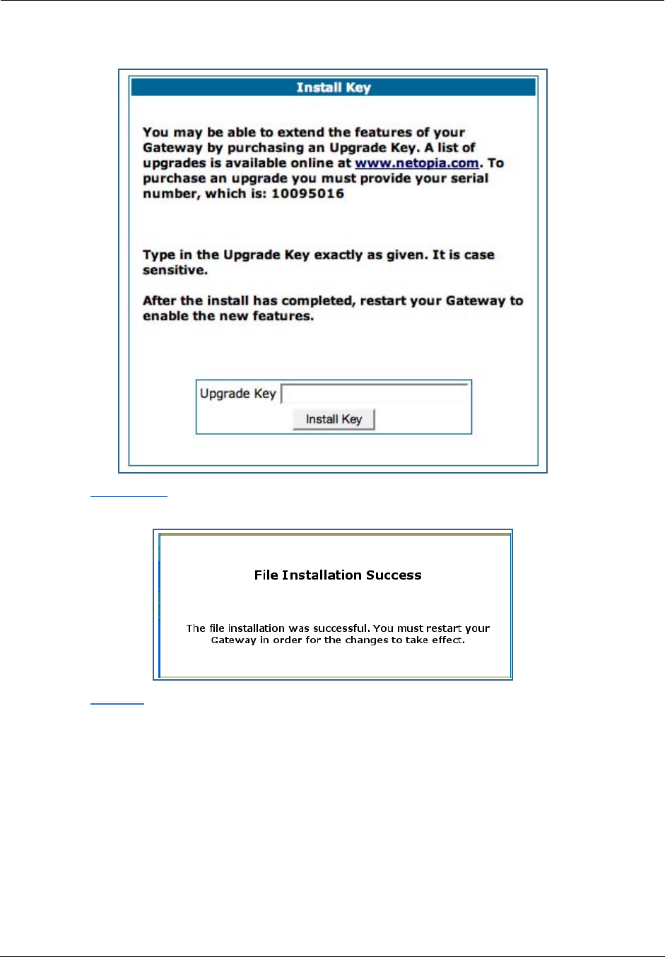
Administrator’s Handbook
188
4. Click the Install Key button.
5. Click the Restart toolbar button.
The Confirmation screen appears.
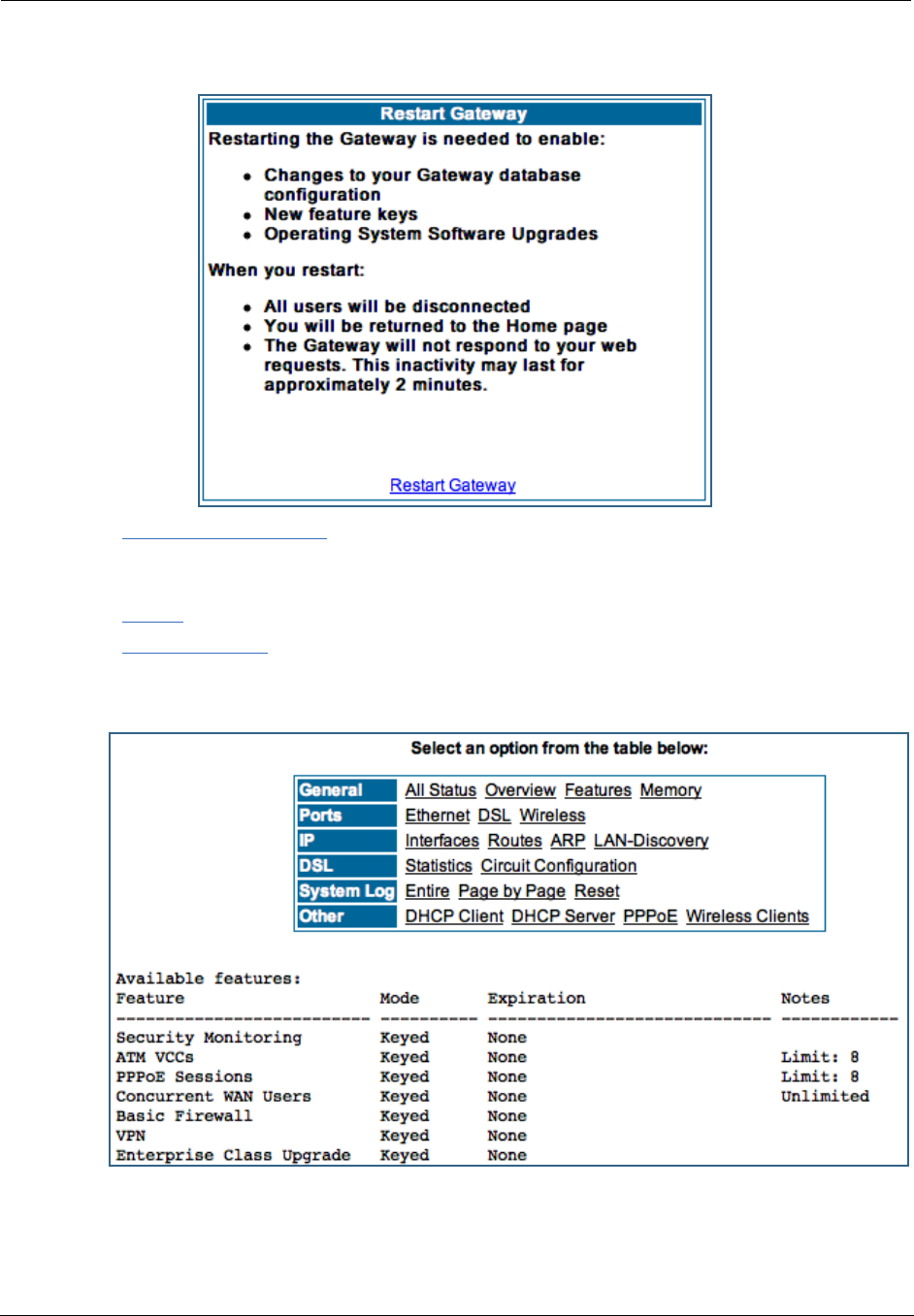
189
6. Click the Restart the Gateway link to confirm.
To check your installed features:
7. Click the Install toolbar button.
8. Click the list of features link.
The System Status page appears with the information from the features link displayed below. You can
check that the feature you just installed is enabled.
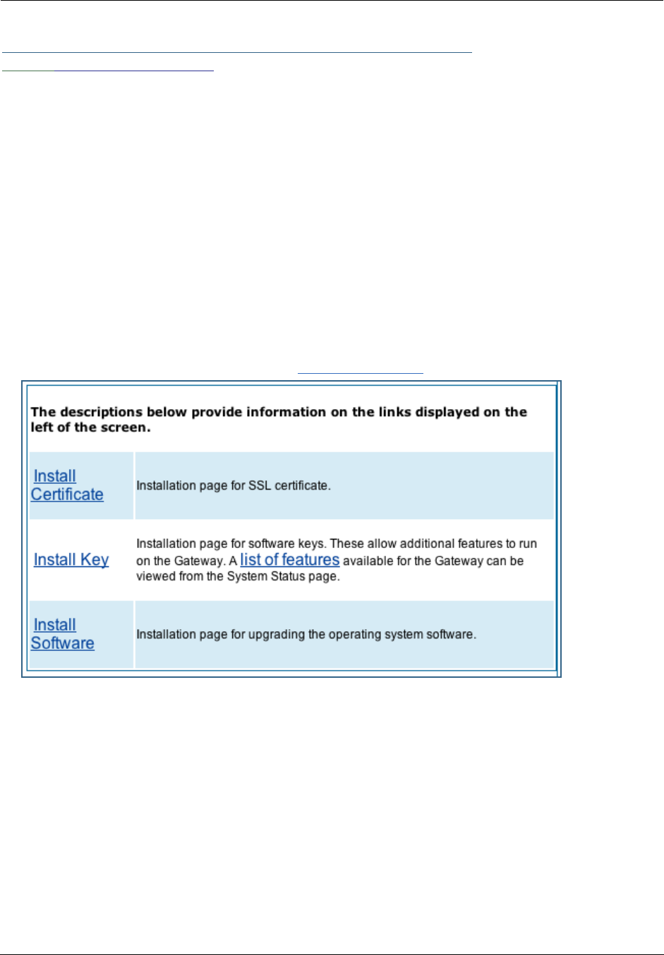
Administrator’s Handbook
190
Link: Install Certificate
Secure Sockets Layer (SSL) is a protocol for transmitting private information over the Internet. SSL uses
two keys to encrypt data: a public key known to everyone and a private or secret key known only to the
recipient of the message.
Netopia Embedded Software Version 7.7.4 uses SSL certificates for TR-069 support.
SSL certificates are issued by trusted Certification Authorities (CAs). The CA digitally signs each certificate.
Each client contains a list of trusted CAs. When an SSL handshake between a server and your Gateway
occurs, the client verifies that the server certificate was issued by a trusted CA. If the CA is not trusted, a
warning will appear. Certificates installed in your Gateway and servers to which it connects verify to each
other that communications between them are encrypted and private.
Certificates are purchased from an issuing Certificate Authority, usually by your corporate IT department or
other service provider, and provided to users for secure communications.
You must obtain a certificate file before you can install it.
1. To install an SSL certificate, click the Install Certificate link.
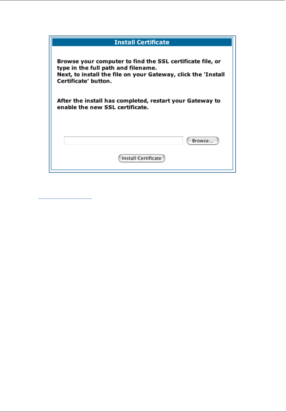
191
The Install Certificate page appears.
2. Browse to the location where you have saved your certificate and select the file, or type
the full path.
3. Click the Install Certificate button.
4. Restart your Gateway.

Administrator’s Handbook
192

193
CHAPTER 4 Basic Troubleshooting
This section gives some simple suggestions for troubleshooting problems with your Gateway’s initial config-
uration.
Before troubleshooting, make sure you have
•read the Quickstart Guide;
•plugged in all the necessary cables; and
•set your PC’s TCP/IP controls to obtain an IP address automatically.
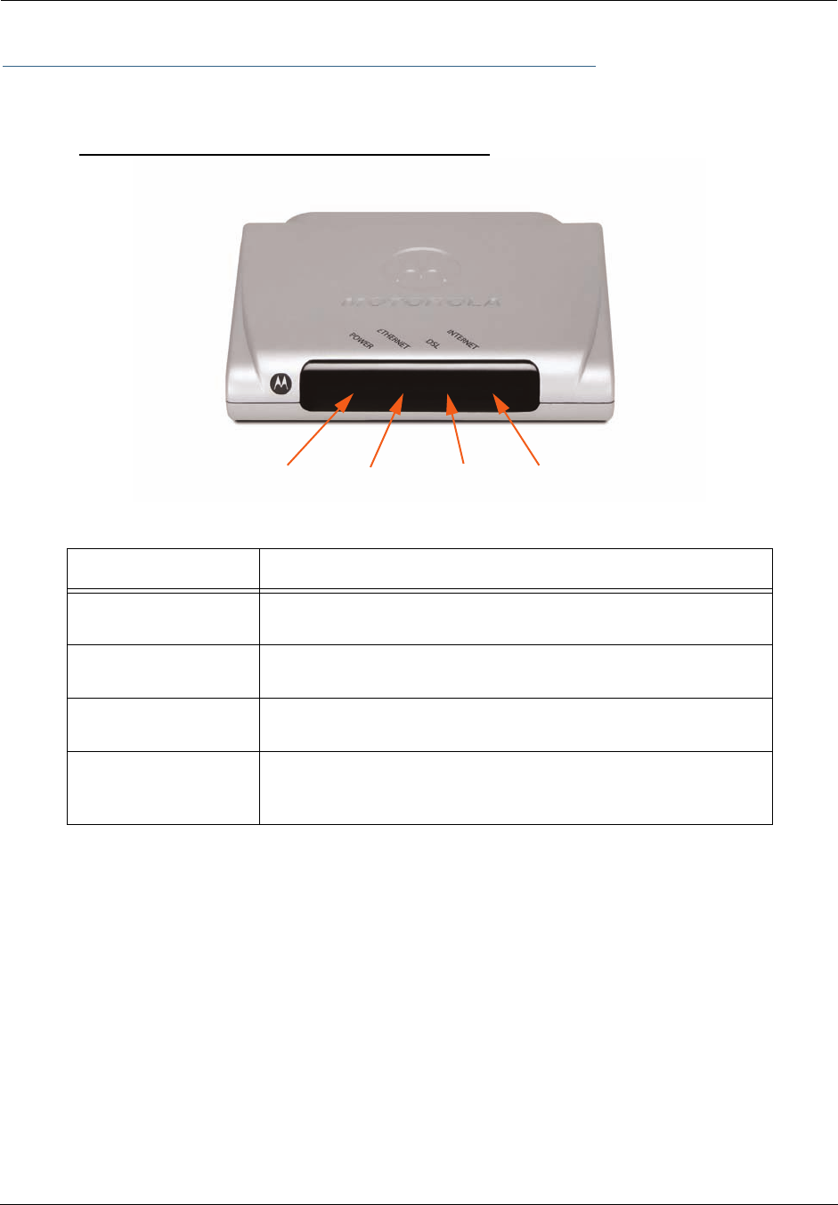
Administrator’s Handbook
194
Status Indicator Lights
The first step in troubleshooting is to check the status indicator lights (LEDs) in the order outlined below.
Motorola Netopia® Gateway 2210 status indicator lights
LED Action
Power Green when power is on. Red if device malfunctions. Flashes Red
when new embedded software is being installed.
Ethernet Solid green when connected. Flash green when there is activity on
the LAN.
DSL Solid green when trained. Blinking green when no line is attached or
when training.
Internet
Solid green when Broadband device is connected. Flashes green for
activity on the WAN port. If the physical link comes up, but PPP or
DHCP fail, the LED turns red.
Power Ethernet DSL Internet
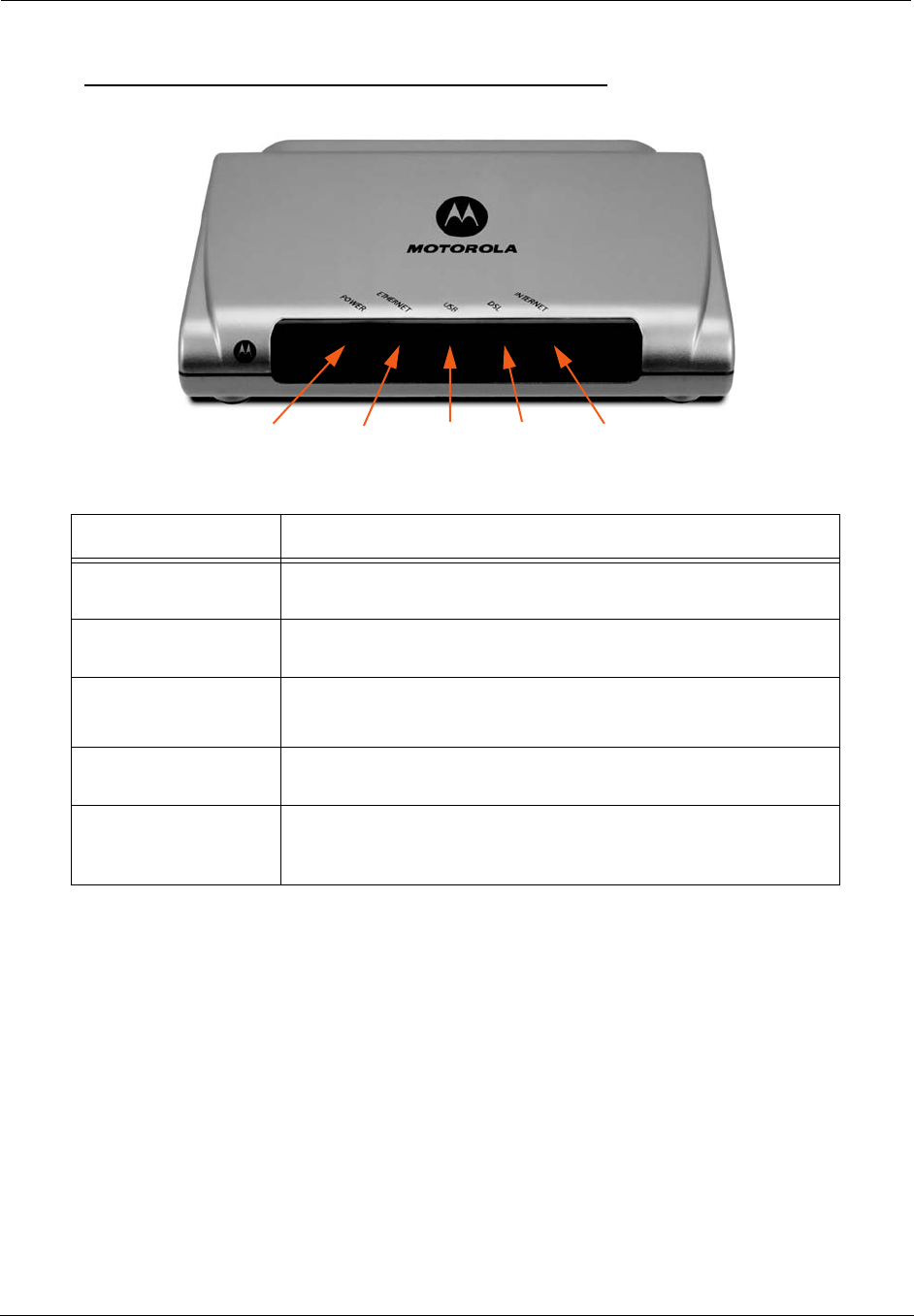
195
Motorola Netopia® Gateway 2240N/2241N status indicator lights
LED Action
Power Green when power is on. Red if device malfunctions. Flashes Red
when new embedded software is being installed.
Ethernet Solid green when connected. Flash green when there is activity on
the LAN.
USB
(Model 2241N only)
Solid green when connected. Flash green when there is activity on
the LAN.
DSL Solid green when trained. Blinking green when no line is attached or
when training.
Internet
Solid green when Broadband device is connected. Flashes green for
activity on the WAN port. If the physical link comes up, but PPP or
DHCP fail, the LED turns red.
Power Ethernet DSLUSB Internet
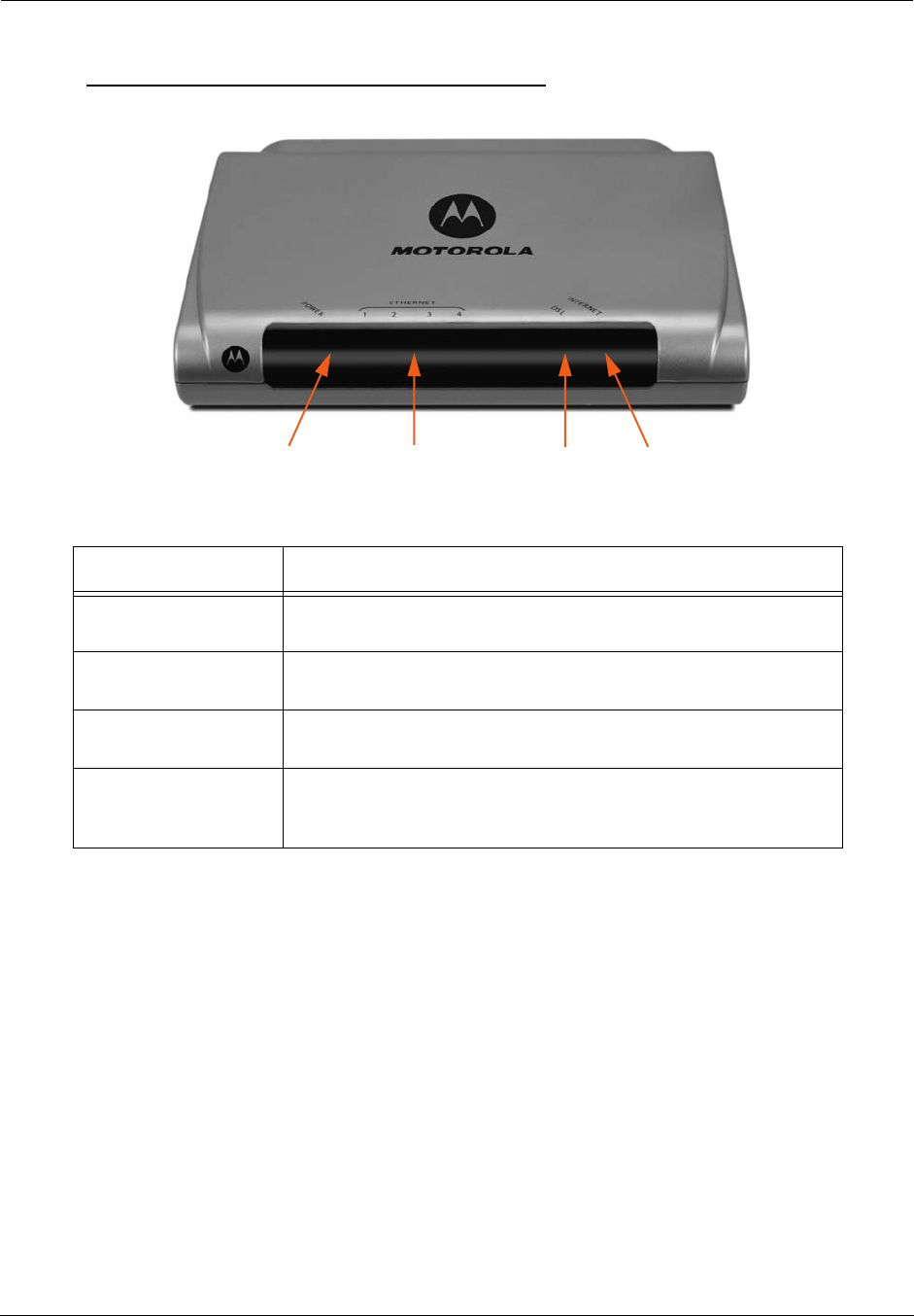
Administrator’s Handbook
196
Motorola Netopia® Gateway 2246N status indicator lights
LED Action
Power Green when power is on. Red if device malfunctions. Flashes Red
when new embedded software is being installed.
Ethernet 1, 2, 3, 4 Solid green when connected. Flash green when there is activity on
the LAN.
DSL Solid green when trained. Blinking green when no line is attached or
when training.
Internet
Solid green when Broadband device is connected. Flashes green for
activity on the WAN port. If the physical link comes up, but PPP or
DHCP fail, the LED turns red.
Power Ethernet 1, 2, 3, 4 DSL Internet
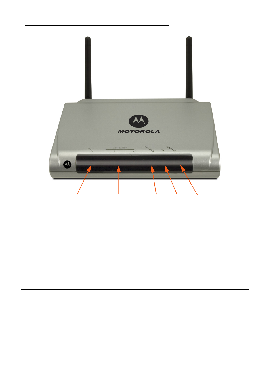
197
Motorola Netopia® Gateway 2247NWG status indicator lights
LED Action
Power Green when power is on. Red if device malfunctions. Flashes Red
when new embedded software is being installed.
Ethernet 1, 2, 3, 4 Solid green when connected. Flash green when there is activity on
the LAN.
Wireless Flashes green when there is activity on the wireless LAN. Off if driver
fails to initialize, or if wireless is disabled.
DSL Solid green when trained. Blinking green when no line is attached or
when training.
Internet
Solid green when Broadband device is connected. Flashes green for
activity on the WAN port. If the physical link comes up, but PPP or
DHCP fail, the LED turns red.
Power Ethernet 1, 2, 3, 4 DSLWireless Internet
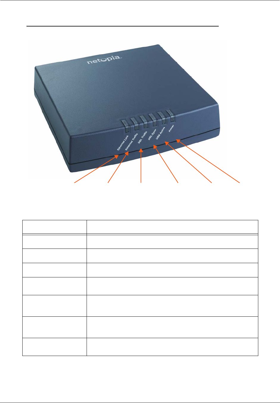
Administrator’s Handbook
198
Motorola Netopia® Gateway 3340(N), 3341(N), 3351(N) status indicator lights
LED Action
Ethernet Link Solid green when connected.
Ethernet Traffic Flashes green when there is activity on the LAN.
DSL Traffic Blinks green when traffic is sent/received over the WAN.
DSL Sync Blinking green with no line attached or training, solid green when
trained with the DSL line.
USB Active
(Model 3341N only)
Solid green when connected; otherwise, not lit.
PPPoE Active
(Model 3340N only)
Solid green when PPPoE is negotiated; otherwise, not lit.
Power Green when power is on. Red if device malfunctions. Flashes Red
when new embedded software is being installed.
PowerUSB ActiveDSL Traffic DSL SyncEthernet TrafficEthernet Link
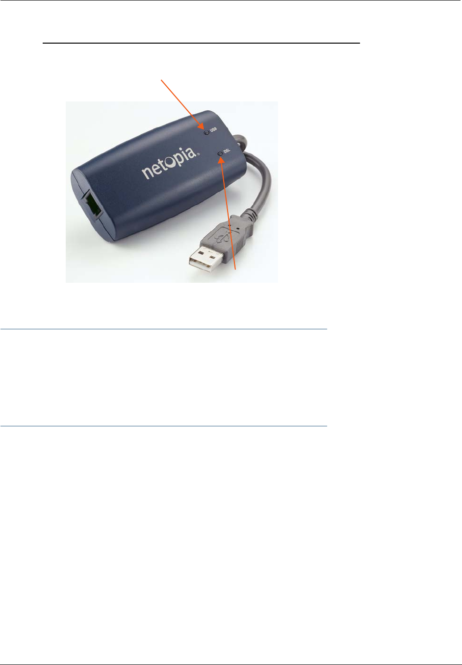
199
Motorola Netopia® Gateway 3342/3342N, 3352/3352N status indicator lights
☛ Special patterns:
• Both LEDs are off during boot (power on boot or warm reboot).
• When the 3342/3352 successfully boots up, both LEDs flash green once.
• Both LEDs are off when the Host OS suspends the device, (e.g. Windows standby/reboot,
device disabled, driver uninstalled, etc.)
USB:
Solid green when USB is connected
DSL:
Blinking green with no line attached or training,
otherwise, not lit
solid green when trained with the DSL line.
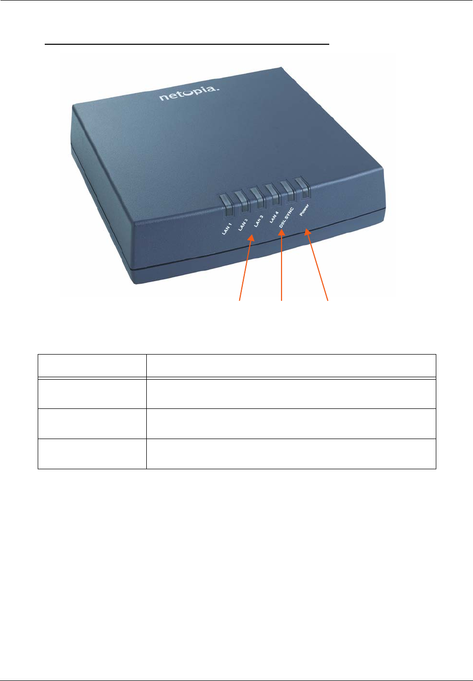
Administrator’s Handbook
200
Motorola Netopia® Gateway 3346(N), 3356(N) status indicator lights
LED Action
Power Green when power is on. Red if device malfunctions. Flashes Red
when new embedded software is being installed.
DSL Sync Blinking green with no line attached or training, solid green when
trained with the DSL line.
LAN 1, 2, 3, 4 Solid green when connected; Flash green when there is activity on the
LAN.
PowerDSL SyncLAN 1, 2, 3, 4
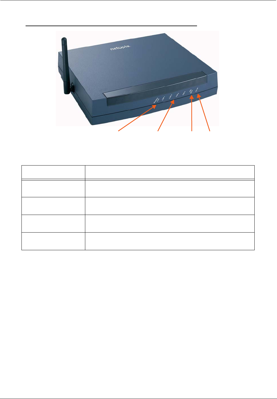
201
Motorola Netopia® Gateway 3347W, 3347(N)WG status indicator lights
LED Action
Power Green when power is on. Red if device malfunctions. Flashes Red
when new embedded software is being installed.
DSL Sync Solid green when trained. Blinking green when no line is attached or
when training. Flashes green for DSL traffic.
Ethernet 1, 2, 3, 4 Solid green when connected. Flash green when there is activity on
the LAN.
Wireless Link Flashes green when there is activity on the wireless LAN. Off if driver
fails to initialize, or if wireless is disabled.
PowerLAN 1, 2, 3, 4 DSL Sync Wireless Link
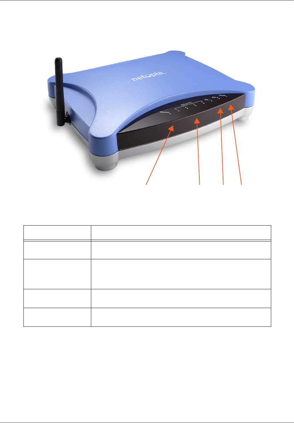
Administrator’s Handbook
202
Motorola Netopia® Gateway MiAVo status indicator lights
LED Action
Power Green when power is on. Red if device malfunctions. Flashes Red
when new embedded software is being installed.
DSL
(DSL 1 & 2: ADSL2+
models only)
Solid green when trained. Blinking green when no line is attached or
when training. Flashes green for DSL traffic.
Ethernet 1, 2, 3, 4 Solid green when connected. Flash green when there is activity on
the LAN.
Wireless Flashes green when there is activity on the wireless LAN. Off if driver
fails to initialize, or if wireless is disabled.
Power
DSL
Ethernet 1, 2, 3, 4
Wireless
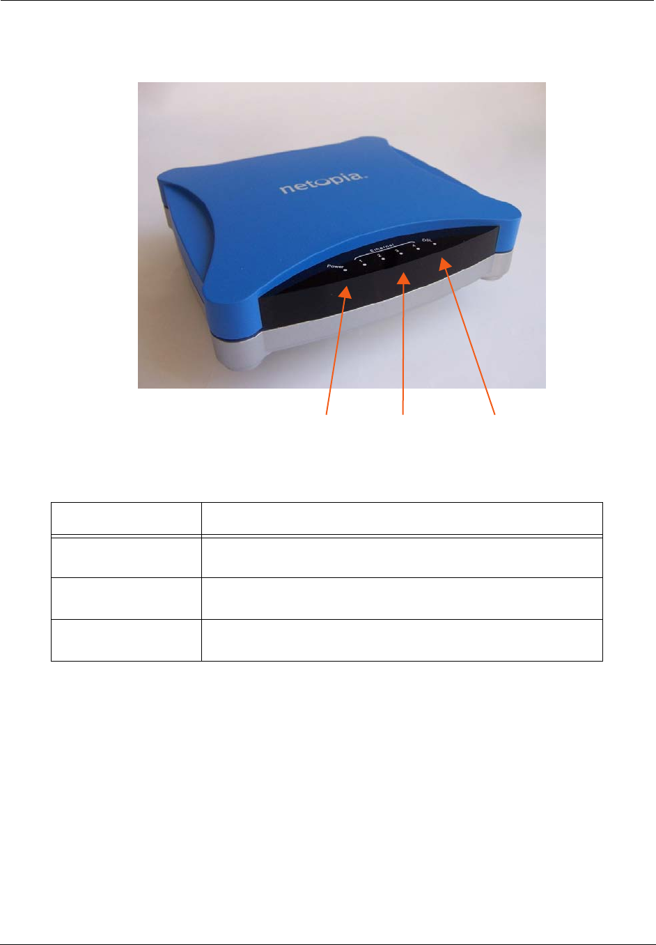
203
Motorola Netopia® Gateway 7346/56-series MiAVo status indicator lights
LED Action
Power Green when power is on. Red if device malfunctions. Flashes Red
when new embedded software is being installed.
Ethernet 1, 2, 3, 4 Solid green when connected. Flash green when there is activity on
the LAN.
DSL Solid green when trained. Blinking green when no line is attached or
when training. Flashes green for DSL traffic.
Power DSLEthernet 1, 2, 3, 4

Administrator’s Handbook
204
LED Function Summary Matrix
If a status indicator light does not look correct, look for these possible problems:
Unlit Solid Green Flashing
Green Solid Red Flashing Red
Power No power Power on N/A System failure Installing new
embedded software
USB Active No signal USB port con-
nected to PC
Activity on the
USB cable
N/A N/A
DSL Sync No signal DSL line synched
with the DSLAM
Attempting to
train with DSLAM
N/A N/A
DSL Traffic No signal N/A Activity on the
DSL cable
N/A N/A
Ethernet
Traffic
No signal N/A Activity on the
Ethernet port
N/A N/A
Ethernet Link No signal Synched with Ether-
net card
N/A N/A N/A
Internet
No signal Broadband device
is connected.
Activity on the
WAN port.
Physical link
established, but
PPP or DHCP
fails.
N/A
Wireless Wireless is
disabled.
Wireless is
enabled.
Activity on the
WLAN.
N/A N/A
LED State Possible problems
Power Unlit
1. Make sure the power switch is in the ON position.
2. Make sure the power adapter is plugged into the 2200-, 3300- or 7000-series DSL Gate-
way properly.
3. Try a known good wall outlet.
4. Replace the power supply and/or unit.
DSL
Sync Unlit
1. Make sure the you are using the correct cable. The DSL cable is the thinner standard tele-
phone cable.
2. Make sure the DSL cable is plugged into the correct wall jack.
3. Make sure the DSL cable is plugged into the DSL port on the 2200-, 3300- or 7000-series
DSL Gateway.
4. Make sure the DSL line has been activated at the central office DSLAM.
5. Make sure the 2200-, 3300- or 7000-series DSL Gateway is not plugged into a micro filter.
EN Link Unlit
Note: EN Link light is inactive if only using USB.
1. Make sure the you are using the Ethernet cable, not the DSL cable. The Ethernet cable is
thicker than the standard telephone cable.
2. Make sure the Ethernet cable is securely plugged into the Ethernet jack on the PC.
3. If plugging a 2200-, 3300- or 7000-series DSL Gateway into a hub the you may need to
plug into an uplink port on the hub, or use an Ethernet cross over cable.
4. Make sure the Ethernet cable is securely plugged into the Ethernet port on the 2200-,
3300- or 7000-series DSL Gateway.
5. Try another Ethernet cable if you have one available.

205
EN Traffic Unlit
1. Make sure you have Ethernet drivers installed on the PC.
2. Make sure the PC’s TCP/IP Properties for the Ethernet Network Control Panel is set to
obtain an IP address via DHCP.
3. Make sure the PC has obtained an address in the 192.168.1.x range. (You may have
changed the subnet addressing.)
4. Make sure the PC is configured to access the Internet over a LAN.
5. Disable any installed network devices (Ethernet, HomePNA, wireless) that are not being
used to connect to the 2200-, 3300- or 7000-series DSL Gateway.
USB
Active Unlit
Note: USB Active light is inactive if only using Ethernet.
1. Make sure you have USB drivers installed on the PC.
2. Make sure the PC’s TCP/IP Properties for the USB Network Control Panel is set to obtain
an IP address via DHCP.
3. Make sure the PC has obtained an address in the 192.168.1.x range. (You may have
changed the subnet addressing.)
4. Make sure the PC is configured to access the Internet over a LAN.
5. Disable any installed network devices (Ethernet, HomePNA, wireless) that are not being
used to connect to the 2200-, 3300- or 7000-series DSL Gateway.
DSL
Traffic Unlit Launch a browser and try to browse the Internet. If the DSL Active light still does not flash,
then proceed to Advanced Troubleshooting below.
Wireless
Link Unlit
•Make sure your client PC(s) have their wireless cards correctly installed and configured.
•Check your client PC(s) TCP/IP settings to make sure they are receiving an IP address from
the wireless Router.
•Check the Gateway’s log for wireless driver failure messages.
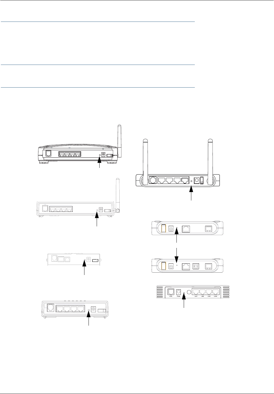
Administrator’s Handbook
206
Factory Reset Switch
(not supported on some models; 3342/3342N/3352/3352N models do not have a reset switch)
Lose your password? This section shows how to reset the Motorola Netopia® Gateway so that you can
access the configuration screens once again.
☛ NOTE: Keep in mind that all of your settings will need to be reconfigured.
If you don't have a password, the only way to access the Motorola Netopia® Gateway is the following:
1. Referring to the following diagram, find the round Reset Switch opening.
2. Carefully insert the point of a pen or an unwound paperclip into the opening.
•If you press the factory default button for less than 1/2 a second, the unit will continue to run as nor-
mal.
•If you press the factory default button for 1 second, when you release it, the Gateway will perform a fac-
tory reset, clear all settings and configurations, and reboot. Do not hold the button down too long (5 –
10 seconds). This will destroy any saved default settings as well.
DSL POWER
4 3 ETHERNET 2 1
RESET
ON
OFF
Power Off / On
LAN
DSL
412
3
Factory Reset Switch:
3347W/3357W
1
Power
4
USB
3
Ethernet
2
DSL On / Off
Factory Reset Switch:
3341/3351
Power Off / On
LAN
DSL
412
3
3346/3356
Factory Reset Switch:
2247NWG
2240N
2241N
2246N
Factory Reset Switch:
Push to clear all settings
Push to clear all settings
Push to clear all settings
Push to clear all settings
Factory Reset Switch:
Push to clear all settings
Factory Reset Switch: Push to clear all settings
2
3Power Off/On
LAN
DSL 41
Factory Reset Switch:
MiaVo
Push to clear all settings

207
CHAPTER 5 Advanced Troubleshooting
Advanced Troubleshooting can be accessed from the Gateway’s Web UI. Point your browser to
http://192.168.1.254
. The main page displays the device status. (If this does not make the Web UI
appear, then do a release and renew in Windows networking to see what the Gateway address really is.)
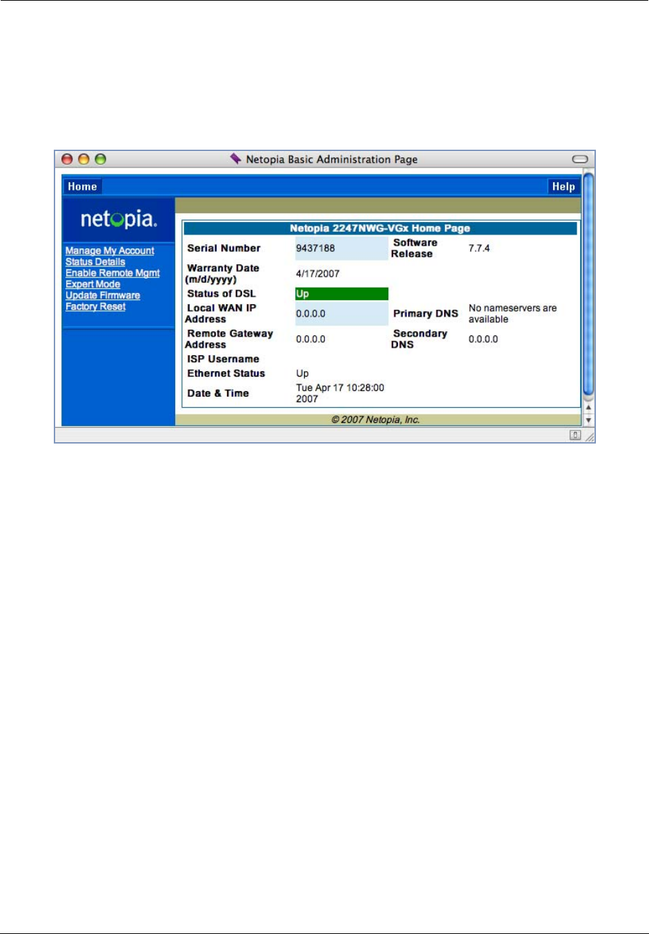
Administrator’s Handbook
208
Home Page
The home page displays basic information about the Gateway. This includes the ISP Username, Connection
Status, Device Address, Remote Gateway Address, DNS-1, and DNS-2. If you are not able to connect to the
Internet, verify the following:
Item Description
Local WAN IP Address This is the negotiated address of the Gateway’s WAN interface. This
address is usually dynamically assigned.
Remote Gateway
Address
This is the negotiated address of the remote router to which this Gate-
way is connected.
Status of Connection ‘Waiting for DSL’ is displayed while the Gateway is training. This
should change to ‘Up’ within two minutes. If not, make sure an RJ-11
cable is used, the Gateway is connected to the correct wall jack, and
the Gateway is not plugged into a micro filter.
‘No Connection’ is displayed if the Gateway has trained but failed the
PPPoE login. This usually means an invalid user name or password.
Go to Expert Mode and change the PPPoE name and password.
‘Up’ is displayed when the ADSL line is synched and the PPPoE (or
other connection method) session is established.
‘Down’ is displayed if the line connection fails.
ISP Username This should be the valid PPPoE username. If not, go to Expert Mode
and change to the correct username.
Device Address This is the negotiated address of the Gateway’s WAN interface.
This address is often dynamically assigned. Make sure this is a valid
address.
If this is not the correct assigned address, go to Expert Mode and ver-
ify the PPPoE address has not been manually assigned.

209
Device Gateway This is the negotiated address of the remote router. Make sure this is
a valid address.
If this is not the correct address, go to Expert Mode and verify the
address has not been manually assigned.
Primary DNS/
Secondary DNS
These are the negotiated DNS addresses. Make sure they are valid
DNS addresses. (Secondary DNS is optional, and may validly be blank
(0.0.0.0).)
If these are not the correct addresses, go to Expert Mode and verify
the addresses have not been manually assigned.
Serial Number This is the unique serial number of your Gateway.
Ethernet Status (if so equipped; not available on 3342/3342N/3352/3352N) This is
the status of your Ethernet connection. If you are connecting via Ether-
net, it should be Up.
USB Status This is the status of your USB connection (if equipped). If you are con-
necting via USB, it should be Up.
Software Release This is the version number of the current embedded software in your
Gateway.
Warranty Date This is the date that your Gateway was installed and enabled.
Date & Time If this is blank, you likely lack a network connection, or your NTP
server information is incorrect.
NOTE: The Home Page may also display Wireless, VoIP or Backup status depending on
model and configuration. See “Wireless” on page 53, “VoIP” on page 120, or “Backup”
on page 133 for more information.
If all of the above seem correct, then access Expert Mode by clicking the
Expert Mode
link.
Item Description
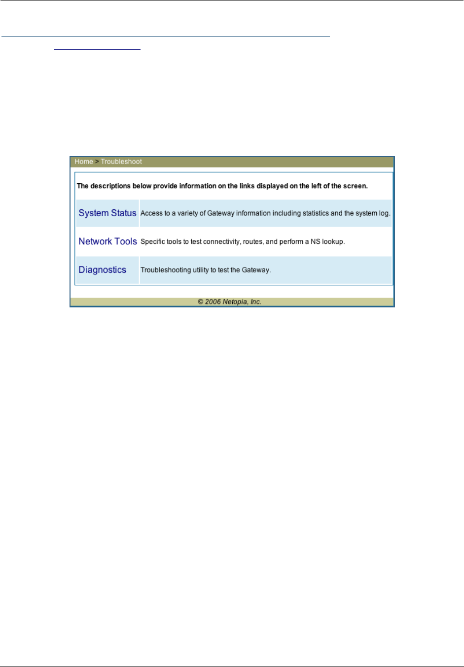
Administrator’s Handbook
210
Button: Troubleshoot
Expert Mode
Expert Mode has advanced troubleshooting tools that are used to pinpoint the exact source of a problem.
Clicking the Troubleshoot tab displays a page with links to System Status, Network Tools, and Diagnostics.
•System Status: Displays an overall view of the system and its condition.
•Network Tools: Includes NSLookup, Ping and TraceRoute.
•Diagnostics: Runs a multi-layer diagnostic test that checks the LAN, WAN, PPPoE, and other connection
issues.
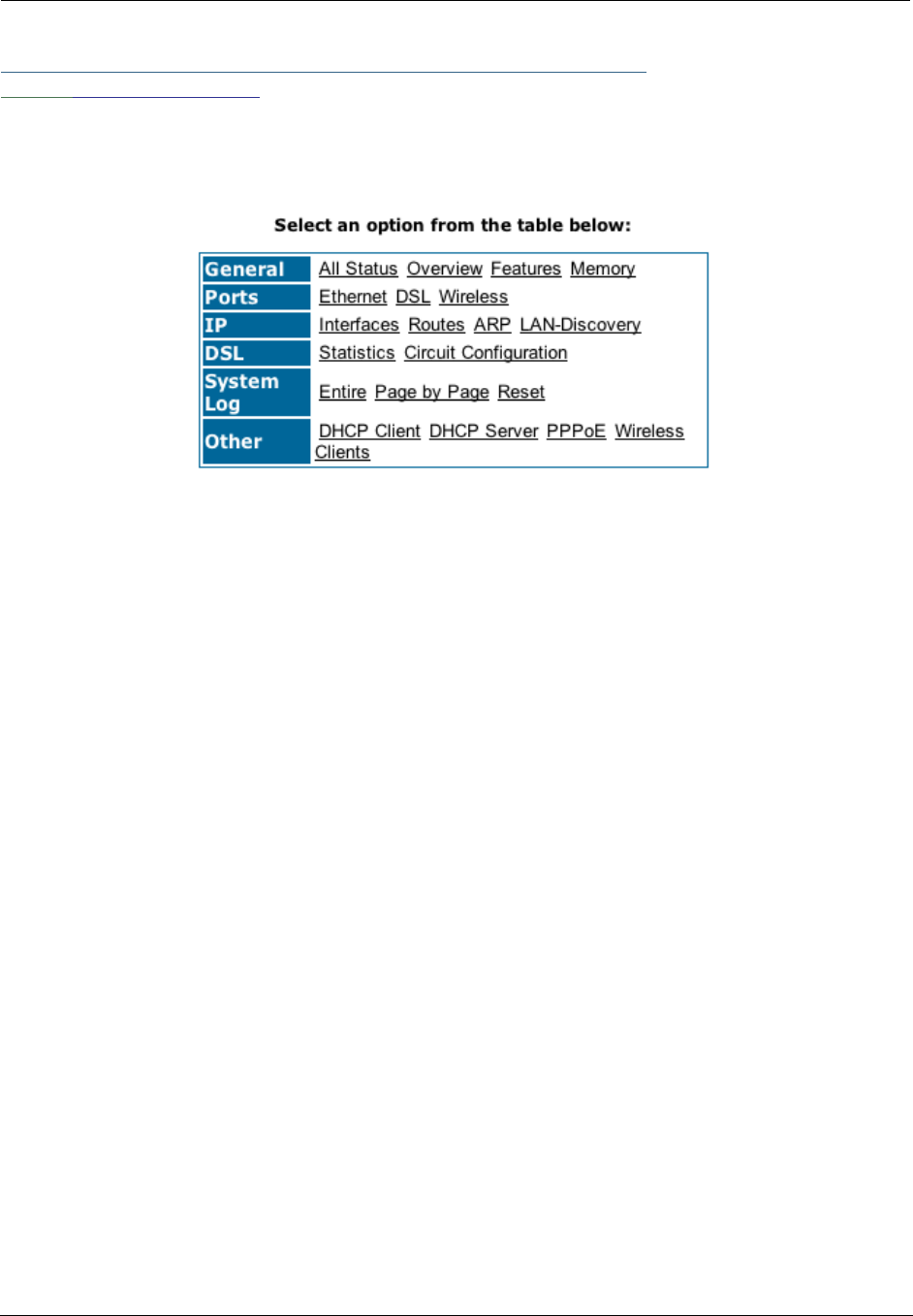
211
Link: System Status
In the system status screen, there are several utilities that are useful for troubleshooting.
Some examples are given in the following pages.

Administrator’s Handbook
212
Link: Ports: Ethernet
The Ethernet port selection shows the traffic sent and received on the Ethernet interface. There should be
frames and bytes on both the upstream and downstream sides. If there are not, this could indicate a bad
Ethernet cable or no Ethernet connection. Below is an example:
Ethernet Driver Statistics - 10/100 Ethernet
Type: 100BASET
Port Status: Link up
General:
Transmit OK : 7862
Receive OK : 4454
Tx Errors : 0
Rx Errors : 0
Rx CRC Errors : 0
Rx Frame Errors : 0
Upper Layers:
Rx No Handler : 0
Rx No Message : 0
Rx Octets : 975576
Rx Unicast Pkts : 4156
Rx Multicast Pkts : 203
Tx Discards : 0
Tx Octets : 2117992
Tx Unicast Pkts : 3789
Tx Multicast Pkts : 4073
Ethernet driver statistics - USB
Port Status: Link down
General:
Transmit OK : 0
Receive OK : 0
Tx Errors : 0
Rx Errors : 0
Tx Octets : 0
Rx Octets : 0
Ethernet driver statistics - 10/100 Ethernet
Type: 100BASET
Port Status: Link up
General:
Transmit OK : 7863
Receive OK : 4458
Tx Errors : 0
Rx Errors : 0
Rx CRC Errors : 0
Rx Frame Errors : 0
Upper Layers:
Rx No Handler : 0
Rx No Message : 0
Rx Octets : 976327
Rx Unicast Pkts : 4159
Rx Multicast Pkts : 204
Tx Discards : 0

213
Link: Ports: DSL
The DSL port selection shows the state of the DSL line, whether it is up or down and how many times the
Gateway attempted to train. The state should indicate ‘up’ for a working configuration. If it is not, check the
DSL cable and make sure it is plugged in correctly and not connected to a micro filter. Below is an example:
ADSL Line State: Up
ADSL Startup Attempts: 5
ADSL Modulation: DMT
Datapump Version: 3.22
Downstream Upstream
---------- ----------
SNR Margin: 18.6 14.0 dB
Line Attenuation: 0.4 4.0 dB
Errored Seconds: 14 3
Loss of Signal: 4 4
Loss of Frame: 0 0
CRC Errors: 0 0
Data Rate: 8000 800

Administrator’s Handbook
214
Link: IP: Interfaces
The IP interfaces selection shows the state and configuration information for your IP LAN and WAN inter-
faces. Below is an example:
IP interfaces:
Ethernet 100BT: ( up broadcast default rip-send v1 rip-receive v1 )
inet 192.168.1.1 netmask 255.255.255.0 broadcast 192.168.1.255
physical address 00-16-cb-39-a9-78 mtu 1500
PPP over Ethernet vcc1: ( up address-mapping broadcast default admin-disabled
rip-send v1 rip-receive v1 )
inet 10.1.2.34 netmask 255.255.255.0 broadcast 10.1.2.1
physical address 00-15-bc-28-b8-67 mtu 1500

215
Link: DSL: Circuit Configuration
The DSL Circuit Configuration screen shows the traffic sent and received over the DSL line as well as the
trained rate (upstream and downstream) and the VPI/VCI. Verify traffic is being sent over the DSL line. If
not, check the cabling and make sure the Gateway is not connected to a micro filter. Also verify the correct
PVC is listed, which should be 0/35 (some providers use other values, such as 8/35. Check with your pro-
vider). If not go to the WAN setup and change the VPI/VCI to its correct value. Below is an example:
ATM port status : Up
Rx data rate (bps) : 8000
Tx data rate (bps) : 800
ATM Virtual Circuits:
VCC # Type VPI VCI Encapsulation
---- ---- --- ----- --------------------------
1 PVC 8 35 PPP over Ethernet (LLC/SNAP encapsulation)
ATM Circuit Statistics:
Rx Frames : 17092 Tx Frames : 25078
Rx Octets : 905876 Tx Octets : 1329134
Rx Errors : 0 Tx Errors : 0
Rx Discards : 0 Tx Discards : 0
No Rx Buffers : 0 Tx Queue Full : 0

Administrator’s Handbook
216
Link: System Log: Entire
The system log shows the state of the WAN connection as well as the PPPoE session. Verify that the
PPPoE session has been correctly established and there are no failures. If there are error messages, go
to the WAN configuration and verify the settings. The following is an example of a successful connection:
Message Log:
Mon Apr 16 10:48:22 2007 L3 KS: Using configured options found in flash
Mon Apr 16 10:48:22 2007 L3 BOOT: Warm start v7.3r0 ----------------------------------
Mon Apr 16 10:48:22 2007 L3 IP address server initialization complete
Mon Apr 16 10:48:22 2007 L4 BR: Using saved configuration options
Mon Apr 16 10:48:22 2007 L4 BR: Netopia SOC OS version 7.3.0 (build r0)
Mon Apr 16 10:48:22 2007 L4 BR: Netopia-3000/9495032 (Netopia-3000, rev 1), PID 1205
Mon Apr 16 10:48:22 2007 L4 BR: last install status: Firmware installed successfully
Mon Apr 16 10:48:22 2007 L4 BR: memory sizes - 2048K Flash, 8192K RAM
Mon Apr 16 10:48:22 2007 L3 BR: Starting kernel
Mon Apr 16 10:48:22 2007 L3 AAL5: initializing service
Mon Apr 16 10:48:22 2007 L4 ATM: Waiting for PHY layer to come up
Mon Apr 16 10:48:22 2007 L3 POE: Initializing PPP over Ethernet service
Mon Apr 16 10:48:22 2007 L4 POE: Binding to Ethernet (ether/vcc1)
Mon Apr 16 10:48:22 2007 L3 BRDG: Configuring port (10/100BT-LAN)
Mon Apr 16 10:48:22 2007 L3 BRDG: Bridge not enabled for WAN.
Mon Apr 16 10:48:22 2007 L3 BRDG: Bridging from one WAN port to another is disabled
Mon Apr 16 10:48:22 2007 L3 BRDG: Initialization complete
Mon Apr 16 10:48:22 2007 L4 IP: Routing between WAN ports is disabled
Mon Apr 16 10:48:22 2007 L4 IP: IPSec client pass through is enabled
Mon Apr 16 10:48:22 2007 L4 IP: Address mapping enabled on interface PPP over Ethernet vcc1
Mon Apr 16 10:48:22 2007 L3 IP: Adding default gateway over PPP over Ethernet vcc1
Mon Apr 16 10:48:22 2007 L3 IP: Initialization complete
Mon Apr 16 10:48:22 2007 L3 IPSec: initializing service
Mon Apr 16 10:48:22 2007 L3 IPSec: No feature key available - service disabled
Mon Apr 16 10:48:22 2007 L3 PPP: PPP over Ethernet vcc1 binding to PPPoE
Mon Apr 16 10:48:22 2007 L3 PPP: PPP over Ethernet vcc1 Port listening for incoming PPP connection requests
.
.
Mon Apr 16 10:48:22 2007 L4 RFC1483-1 up
Mon Apr 16 10:48:22 2007 L3 Service-Name=ANY
Mon Apr 16 10:48:22 2007 L3 Host-Uniq 00000001
Mon Apr 16 10:48:22 2007 L3 AC-Name=62011050058192-SMS1800
Mon Apr 16 10:48:22 2007 L3 Service-Name=ANY
Mon Apr 16 10:48:22 2007 L3 lcp: LCP Send Config-Request+
Mon Apr 16 10:48:22 2007 L3 MAGIC 0x2dee0000+
Mon Apr 16 10:48:22 2007 L3 lcp: LCP Recv Config-Req:+
Mon Apr 16 10:48:22 2007 L3 MRU(1492) (ACK) AUTHTYPE(c223) (CHAP) (ACK) MAGICNUMBER
Mon Apr 16 10:48:22 2007 L3 (4403604) (ACK)
Mon Apr 16 10:48:22 2007 L3 lcp: returning Configure-Ack
Mon Apr 16 10:48:22 2007 L3 chap: received challenge, id 1
Mon Apr 16 10:48:22 2007 L3 chap: received success, id 1
Mon Apr 16 10:48:22 2007 L3 ipcp: IPCP Config-Request+
Mon Apr 16 10:48:22 2007 L3 ADDR(0x0) DNS(0x0) DNS2(0x0) WINS(0x0) WINS2(0x0)
Mon Apr 16 10:48:22 2007 L3 ipcp: IPCP Recv Config-Req:+
Mon Apr 16 10:48:22 2007 L3 ADDR(143.137.199.254) (ACK)
Mon Apr 16 10:48:22 2007 L3 ipcp: returning Configure-ACK
Mon Apr 16 10:48:22 2007 L3 ipcp: IPCP Config-Request+
Mon Apr 16 10:48:22 2007 L3 ADDR(0x0) DNS(0x0) DNS2(0x0)
Mon Apr 16 10:48:22 2007 L3 ipcp: IPCP Config-Request+
Mon Apr 16 10:48:22 2007 L3 ADDR(0x8f89c702) DNS(0x8f89320a) DNS2(0x8f898909)
Mon Apr 16 10:48:22 2007 L3 ipcp: negotiated remote IP address 143.137.199.254
Mon Apr 16 10:48:22 2007 L3 ipcp: negotiated IP address 143.137.199.2
Mon Apr 16 10:48:22 2007 L3 ipcp: negotiated TCP hdr compression off
Mon Apr 16 10:48:22 2007 L3 NTP: Update system date & time
Mon Apr 16 10:50:02 L4 TS: "admin" logging in on serial port 0
Mon Apr 16 10:50:02 L4 TS: "Admin" completed login: Full Read/Write access
Mon Apr 16 10:50:02 L4 TS: "Admin" completed login: Full Read/Write access

217
Link: Diagnostics
The diagnostics section tests a number of different things at the same time, including the DSL line, the
Ethernet inter face and the PPPoE session.
The following table summarizes the possible results.
CODE Description
PASS The test was successful.
FAIL The test was unsuccessful.
SKIPPED The test was skipped because a test on which it depended failed, or it was not sup-
ported by the service provider equipment to which it is connected, or it does not
apply.
PENDING The test timed out without producing a result. Try running the test again.
WARNING The test was unsuccessful. The Service Provider equipment your Gateway connects to
may not support this test.
==== Checking LAN Interfaces
Check Ethernet LAN connect : PASS
Check IP connect to Ethernet (LAN) : PASS
Pinging Gateway : PASS
Check MAC-Bridge connect to Ethernet (LAN) : PASS
==== Checking DSL (WAN) Interfaces
Check DSL Synchronization : PASS
Check ATM Cell-Delineation : PASS
ATM OAM Segment Ping through (vcc1) : WARNING
*** Don't worry, your service provider may not support this test
ATM OAM End-To-End Ping through (vcc1) : WARNING
*** Don't worry, your service provider may not support this test
Check Ethernet connect to AAL5 (vcc1) : PASS
Check PPPOE connect to Ethernet (vcc1) : PASS
Check PPP connect to PPPOE (vcc1) : PASS
Check IP connect to PPP (vcc1) : PASS
Pinging Gateway : PASS
==== Checking Miscellaneous
Check DNS- Query for netopia.com : SKIPPED
Ping DNS Server Primary IP Address : SKIPPED
TEST DONE
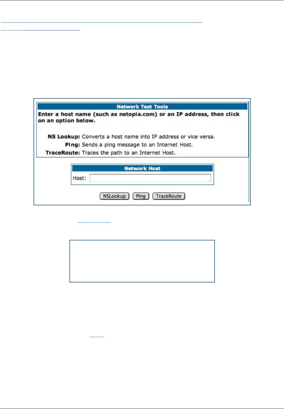
Administrator’s Handbook
218
Link: Network Tools
Three test tools are available from this page.
•NSLookup - converts a domain name to its IP address and vice versa.
•Ping - tests the “reachability” of a particular network destination by sending an ICMP echo request and
waiting for a reply.
•TraceRoute - displays the path to a destination by showing the number of hops and the router
addresses of these hops.
1. To use the NSLookup capability, type an address (domain name or IP address) in the
text box and click the
NSLookup
button
Example: Show the IP Address for grosso.com.
Result: The DNS Server doing the lookup is displayed in the Server: and Address: fields. If the Name
Server can find your entry in its table, it is displayed in the Name: and Address: fields.
PING: The network tools section sends a PING from the Gateway to either the LAN or WAN to verify connec-
tivity. A PING could be either an IP address (163.176.4.32) or Domain Name (www.netopia.com).
2. To use the Ping capability, type a destination address (domain name or IP address) in
the text box and click the
Ping
button.
Example: Ping to grosso.com.
Server : controller2.netopia.com
Address : 143.137.137.9
Name : www.grosso.com
Address : 192.150.14.120

219
Result: The host was reachable with four out of five packets sent.
ping www.grosso.com
Pinging 192.150.14.120 from local address 143.137.199.8 (timer gran. 100 ms)...
Ping size: 100 Ping count: 5
ICMP echo reply from 192.150.14.120, 200 ms
ICMP echo reply from 192.150.14.120, 100 ms
No ping response.
ICMP echo reply from 192.150.14.120, 100 ms
ICMP echo reply from 192.150.14.120, 100 ms
--- 192.150.14.120 ping statistics ---
5 packets transmitted, 4 packets received, 20% packet loss

Administrator’s Handbook
220
Below are some specific tests:
3. To use the TraceRoute capability, type a destination address (domain name or IP
address) in the text box and click the
TraceRoute
button.
Action If PING is not successful, possible causes are:
From the Gateway's Network
Tools page:
Ping the internet default gateway IP
address
DSL is down, DSL or ATM settings are incorrect; Gate-
way’s IP address or subnet mask are wrong; gateway
router is down.
Ping an internet site by IP address Gateway’s default gateway is incorrect, Gateway’s sub-
net mask is incorrect, site is down.
Ping an internet site by name DNS is not properly configured on the Gateway; config-
ured DNS servers are down; site is down.
From a LAN PC:
Ping the Gateway’s LAN IP address IP address and subnet mask of PC are not on the same
scheme as the Gateway; cabling or other connectivity
issue.
Ping the Gateway’s WAN IP address Default gateway on PC is incorrect.
Ping the Gateway’s internet default
gateway IP address
NAT is off on the Gateway and the internal IP addresses
are private.
Ping an internet site by IP address PC's subnet mask may be incorrect, site is down.
Ping an internet site by name DNS is not properly configured on the PC, configured
DNS servers are down, site is down.

221
Example: Show the path to the grosso.com site.
Result: It took 20 hops to get to the grosso.com web site.
traceroute www.grosso.com
Traceroute to 192.150.14.120 from address 143.137.199.8 (timer gran. 100 ms)...
30 hops max, 56 byte packets
1 143.137.199.254 100 ms 100 ms 0 ms
2 143.137.50.254 100 ms 0 ms 0 ms
3 143.137.137.254 100 ms 0 ms 100 ms
4 141.154.96.161 0 ms 0 ms 100 ms
5 141.154.8.13 0 ms 100 ms 0 ms
6 4.24.92.97 0 ms 100 ms 0 ms
7 4.24.4.225 100 ms 0 ms 100 ms
8 4.24.7.121 0 ms 0 ms 100 ms
9 4.24.7.113 0 ms 100 ms 0 ms
10 4.24.6.50 100 ms 0 ms 100 ms
11 4.24.10.86 0 ms 100 ms 100 ms
12 4.24.6.234 0 ms 100 ms 0 ms
13 192.205.32.153 100 ms 0 ms 100 ms
14 12.123.1.122 100 ms 0 ms 100 ms
15 12.122.2.173 100 ms 100 ms 100 ms
16 12.122.2.153 100 ms 100 ms 100 ms
17 12.122.5.149 100 ms 200 ms 100 ms
18 12.123.12.189 100 ms 100 ms 200 ms
19 12.124.32.34 100 ms 100 ms 200 ms
20 192.150.14.120 100 ms ! 100 ms ! 100 ms !

Administrator’s Handbook
222

223
CHAPTER 6 Command Line Interface
The Motorola Netopia® Gateway operating software includes a command line interface (CLI) that lets you
access your Motorola Netopia® Gateway over a telnet connection. You can use the command line interface
to enter and update the unit’s configuration settings, monitor its performance, and restart it.
This chapter covers the following topics:
•“Overview” on page 224
•“Starting and Ending a CLI Session” on page 226
•“Using the CLI Help Facility” on page 226
•“About SHELL Commands” on page 227
•“SHELL Commands” on page 228
•“About CONFIG Commands” on page 240
•“CONFIG Commands” on page 243
CONFIG Commands
“Remote ATA Configuration Commands” on page 243 “PPPoE with IPoE Settings” on page 282
“DSL Commands” on page 245 “Ethernet Por t Settings” on page 283
“Bridging Settings” on page 246 “802.3ah Ethernet OAM Settings” on page 284
“DHCP Settings” on page 248 “Command Line Interface Preference Settings” on
page 285
“DMT Settings” on page 254 “Port Renumbering Settings” on page 286
“Domain Name System Settings” on page 255 “Security Settings” on page 287
“IGMP Settings” on page 257 “System Settings” on page 298
“IP Settings” on page 259 “Syslog” on page 301
“Queue Configuration” on page 271 “Wireless Settings (supported models)” on page 303
“IPMaps Settings” on page 277 “VLAN Settings” on page 311
“Network Address Translation (NAT) Default Settings” on
page 278
“VoIP settings” on page 316
“Network Address Translation (NAT) Pinhole Settings” on
page 278
“UPnP settings” on page 321
“PPPoE /PPPoA Settings” on page 279 “DSL Forum settings” on page 321
“SNMP Settings” on page 297 “Backup IP Gateway Settings” on page 323

Administrator’s Handbook
224
Overview
The CLI has two major command modes: SHELL and CONFIG. Summary tables that list the commands
are provided below. Details of the entire command set follow in this section.
SHELL Commands
Command Status and/or Description
arp to send ARP request
atmping to send ATM OAM loopback
clear to erase all stored configuration information
clear_certificate to remove an SSL certificate that has been installed
clear_log to erase all stored log info in flash memory
configure to configure unit's options
diagnose to run self-test
download to download config file
etheroam to show Ethernet OAM info
exit to quit this shell
help to get more: “help all” or “help help”
install to download and program an image into flash
license to enter an upgrade key to add a feature
log to add a message to the diagnostic log
loglevel to report or change diagnostic log level
netstat to show IP information
nslookup to send DNS query for host
ping to send ICMP Echo request
quit to quit this shell
reset to reset subsystems
restart to restart unit
show to show system information
start to start subsystem
status to show basic status of unit
telnet to telnet to a remote host
traceroute to send traceroute probes
upload to upload config file
view to show configuration information
voip to show VoIP info
who to show who is using the shell

225
CONFIG Commands
Command Verbs Status and/or Description
delete Delete configuration list data
help Help command option
save Save configuration data
script Print configuration data
set Set configuration data
validate Validate configuration settings
view View configuration data
Keywords
ata ATA remote config options
atm ATM options (DSL only)
backup Backup gateway options
bridge Bridge options
dhcp Dynamic Host Configuration Protocol options
dmt DMT ADSL options
diffserv Differentiated Services options
dns Domain Name System options
dslf-cpewan TR-069 CPE WAN management
dslf-lanmgnt TR-064 LAN management
dynamic-dns Dynamic DNS client options
ethernet Ethernet options
ethernet-MAC-override Ethernet options
igmp IGMP configuration options
ip TCP/IP protocol options
ip-maps IPmaps options
nat-default Network Address Translation default options
pinhole Pinhole options
ppp Peer-to-Peer Protocol options
wan-over-ether PPP over Ethernet options
preferences Shell environment settings
queue bandwidth queueing options
radius RADIUS Server options
security Security options
servers Internal Server options
snmp SNMP management options
system Gateway’s system options
upnp UPnP options
vdsl VDSL tuning options
vlan VLAN options
wireless Wireless LAN options
Command Utilities
top Go to top level of configuration mode
quit Exit from configuration mode; return to shell mode
exit Exit from configuration mode; return to shell mode

Administrator’s Handbook
226
Starting and Ending a CLI Session
Open a telnet connection from a workstation on your network.
You initiate a telnet connection by issuing the following command from an IP host that supports telnet, for
example, a personal computer running a telnet application such as NCSA Telnet.
telnet <ip_address>
You must know the IP address of the Motorola Netopia® Gateway before you can make a telnet connection
to it. By default, your Motorola Netopia® Gateway uses 192.168.1.254 as the IP address for its LAN inter-
face. You can use a Web browser to configure the Motorola Netopia® Gateway IP address.
Logging In
The command line interface log-in process emulates the log-in process for a UNIX host. To logon, enter the
username (either admin or user), and your password.
•Entering the administrator password lets you display and update all Motorola Netopia® Gateway set-
tings.
•Entering a user password lets you display (but not update) Motorola Netopia® Gateway settings.
When you have logged in successfully, the command line interface lists the username and the security level
associated with the password you entered in the diagnostic log.
Ending a CLI Session
You end a command line interface session by typing quit from the SHELL node of the command line inter-
face hierarchy.
Saving Settings
In CONFIG mode, the save command saves the working copy of the settings to the Gateway. The Gateway
automatically validates its settings when you save and displays a warning message if the configuration is
not correct.
Using the CLI Help Facility
The help command lets you display on-line help for SHELL and CONFIG commands. To display a list of the
commands available to you from your current location within the command line inter face hierarchy, enter
help.
To obtain help for a specific CLI command, type help <command>. You can truncate the
help
command
to
h
or a question mark when you request help for a CLI command.

227
About SHELL Commands
You begin in SHELL mode when you start a CLI session. SHELL mode lets you perform the following tasks
with your Motorola Netopia® Gateway:
•Monitor its performance
•Display and reset Gateway statistics
•Issue administrative commands to restart Motorola Netopia® Gateway functions
SHELL Prompt
When you are in SHELL mode, the CLI prompt is the name of the Motorola Netopia® Gateway followed by a
right angle bracket (>). For example, if you open a CLI connection to the Motorola Netopia® Gateway named
“Netopia-3000/9437188,” you would see
Netopia-3000/9437188>
as your CLI prompt.
SHELL Command Shortcuts
You can truncate most commands in the CLI to their shortest unique string. For example, you can use the
truncated command
q
in place of the full
quit
command to exit the CLI. However, you would need to enter
rese
for the
reset
command, since the first characters of
reset
are common to the
restart
command.
The only commands you cannot truncate are
restart
and
clear
. To prevent accidental interruption of com-
munications, you must enter the
restart
and
clear
commands in their entirety.
You can use the Up and Down arrow keys to scroll backward and forward through recent commands you
have entered. Alternatively, you can use the
!!
command to repeat the last command you entered.

Administrator’s Handbook
228
SHELL Commands
Common Commands
arp
nnn.nnn.nnn.nnn
Sends an Address Resolution Protocol (ARP) request to match the
nnn.nnn.nnn.nnn
IP address to an
Ethernet hardware address.
clear [yes]
Clears the configuration settings in a Motorola Netopia® Gateway. If you do not use the optional yes qual-
ifier, you are prompted to confirm the clear command.
clear_certificate
Removes an SSL certificate that has been installed.
clear_log
Erases the log information stored in flash if persistent logging is enabled.
configure
Puts the command line interface into Configure mode, which lets you configure your Motorola Netopia®
Gateway with Config commands. Config commands are described starting on page 225.
diagnose
Runs a diagnostic utility to conduct a series of internal checks and loopback tests to verify network connec-
tivity over each interface on your Motorola Netopia® Gateway. The console displays the results of each test
as the diagnostic utility runs. If one test is dependent on another, the diagnostic utility indents its entry in
the console window. For example, the diagnostic utility indents the Check IP connect to Ethernet (LAN)
entry, since that test will not run if the Check Ethernet LAN Connect test fails.
Each test generates one of the following result codes:
download [
server_address
] [
filename
] [confirm]
This command installs a file of configuration parameters into the Motorola Netopia® Gateway from a TFTP
(Trivial File Transfer Protocol) server. The TFTP server must be accessible on your Ethernet network.
CODE Description
PASS The test was successful.
FAIL The test was unsuccessful.
SKIPPED The test was skipped because a test on which it depended failed, or
because the test did not apply to your particular setup or model.
PENDING The test timed out without producing a result. Try running the test again.

229
You can include one or more of the following arguments with the download command. If you omit argu-
ments, the console prompts you for this information.
•The
server_address
argument identifies the IP address of the TFTP server from which you want to
copy the Motorola Netopia® Gateway configuration file.
•The
filename
argument identifies the path and name of the configuration file on the TFTP server.
•If you include the optional confirm keyword, the download begins as soon as all information is entered.
You can also download an SSL certificate file from a trusted Certification Authority (CA), on platforms that
support SSL, as follows:
download [-cert] [
server_address
] [
filename
] [confirm]
install [
server_address
] [
filename
] [confirm]
(Not supported on model 3342/3352)
Downloads a new version of the Motorola Netopia® Gateway operating software from a TFTP (Trivial File
Transfer Protocol) server, validates the software image, and programs the image into the Motorola Neto-
pia® Gateway memory. After you install new operating software, you must restart the Motorola Netopia®
Gateway.
The
server_address
argument identifies the IP address of the TFTP server on which your Motorola Neto-
pia® Gateway operating software is stored. The
filename
argument identifies the path and name of the
operating software file on the TFTP server.
If you include the optional keyword
confirm
, you will not be prompted to confirm whether or not you want
to perform the operation.
license [key]
This command installs a software upgrade key. An upgrade key is a purchased item, based on the serial
number of the gateway.
log
message_string
Adds the message in the
message_string
argument to the Motorola Netopia® Gateway diagnostic log.
loglevel [
level
]
Displays or modifies the types of log messages you want the Motorola Netopia® Gateway to record. If you
enter the loglevel command without the optional
level
argument, the command line interface dis-
plays the current log level setting.
You can enter the loglevel command with the
level
argument to specify the types of diagnostic mes-
sages you want to record. All messages with a level number equal to or greater than the level you specify
are recorded. For example, if you specify loglevel 3, the diagnostic log will retain high-level informational
messages (level 3), warnings (level 4), and failure messages (level 5).
Use the following values for the
level
argument:

Administrator’s Handbook
230
•1 or low – Low-level informational messages or greater; includes trivial status messages.
•2 or medium – Medium-level informational messages or greater; includes status messages that can
help monitor network traffic.
•3 or high – High-level informational messages or greater; includes status messages that may be signif-
icant but do not constitute errors.
•4 or warning – Warnings or greater; includes recoverable error conditions and useful operator infor-
mation.
•5 or failure – Failures; includes messages describing error conditions that may not be recover-
able.
netstat -i
Displays the IP interfaces for your Motorola Netopia® Gateway.
netstat -r
Displays the IP routes stored in your Motorola Netopia® Gateway.
nslookup {
hostname
|
ip_address
}
Performs a domain name system lookup for a specified host.
•The
hostname
argument is the name of the host for which you want DNS information; for example,
nslookup klaatu
.
•The
ip_address
argument is the IP address, in dotted decimal notation, of the device for which you
want DNS information.
ping [-s
size
] [-c
count
]{
hostname
|
ip_address
}
Causes the Motorola Netopia® Gateway to issue a series of ICMP Echo requests for the device with the
specified name or IP address.
•The
hostname
argument is the name of the device you want to ping; for example,
ping ftp.neto-
pia.com
.
•The
ip_address
argument is the IP address, in dotted decimal notation, of the device you want to
locate. If a host using the specified name or IP address is active, it returns one or more ICMP Echo
replies, confirming that it is accessible from your network.
•The
-s
size
argument lets you specify the size of the ICMP packet.
•The
-c
count
argument lets you specify the number of ICMP packets generated for the ping request.
Values greater than 250 are truncated to 250.
You can use the ping command to determine whether a hostname or IP address is already in use on your
network. You cannot use the ping command to ping the Motorola Netopia® Gateway’s own IP address.
quit
Exits the Motorola Netopia® Gateway command line interface.

231
reset arp
Clears the Address Resolution Protocol (ARP) cache on your unit.
reset atm
Resets the Asynchronous Transfer Mode (ATM) statistics.
reset cdmode
This command will set up one boot flag so that the next time a 3342N/3352N restarts or reboots (power
cycle), the Gateway will boot into CD-ROM mode instead of Gateway mode.
This command is only for the 3342N/3352N. If the Gateway is not a 3342N/3352N this command does
nothing but returns the message: "CD mode is not supported on this platform."
reset crash
Clears crash-dump information, which identifies the contents of the Motorola Netopia® Gateway registers
at the point of system malfunction.
reset dhcp server
Clears the DHCP lease table in the Motorola Netopia® Gateway.
reset diffserv
Resets the Differentiated Services (diffserv) statistics.
reset enet [ all ]
Resets Ethernet statistics to zero. Resets individual LAN switch port statistics as well as wireless and WAN
Ethernet statistics (where applicable).
reset heartbeat
Restarts the heartbeat sequence.
reset ipmap
Clears the IPMap table (NAT).
reset log
Rewinds the diagnostic log display to the top of the existing Motorola Netopia® Gateway diagnostic log. The
reset log command does not clear the diagnostic log. The next show log command will display infor-
mation from the beginning of the log file.

Administrator’s Handbook
232
reset security-log
Clears the security monitoring log to make room to capture new entries.
reset wan-users [all |
ip-address
]
This function disconnects the specified WAN User to allow for other users to access the WAN. This function
is only available if the number of WAN Users is restricted and NAT is on. Use the all parameter to discon-
nect all users. If you logon as Admin you can disconnect any or all users. If you logon as User, you can only
disconnect yourself.
reset wan
This function resets WAN interface statistics.
reset wepkeys
This function allows you to force your wireless WEP key settings back to the default values, if there are
default values. For example, on some models, the WEP keys are based on the serial number. This allows
you to get back those default settings if you have changed them without the need to reset the entire config-
uration of the unit.
restart [
seconds
]
Restarts your Motorola Netopia® Gateway. If you include the optional
seconds
argument, your Motorola
Netopia® Gateway will restart when the specified number of seconds have elapsed. You must enter the
complete restart command to initiate a restart.
show all-info
Displays all settings currently configured in the Motorola Netopia® Gateway.
show backup
Displays the status of the Backup port, Up or Down, and reports the current port in use.
show bridge interfaces
Displays bridge interfaces maintained by the Motorola Netopia® Gateway.
show bridge table
Displays the bridging table maintained by the Motorola Netopia® Gateway.
show config
Dumps the Motorola Netopia® Gateway’s configuration script just as the script command does in config
mode.

233
show crash
Displays the most recent crash information, if any, for your Motorola Netopia® Gateway.
show dhcp agent
Displays DHCP relay-agent leases.
show dhcp server leases
Displays the DHCP leases stored in RAM by your Motorola Netopia® Gateway.
show diffserv
Displays the Differentiated Services and QoS values configured in the Motorola Netopia® Gateway.
show dslf device-association
Displays LAN devices that conform with the TR111 Gateway requirement. It displays - IP Address, Manufac-
ture OUI and Serial number.
show enet [ all ]
Displays Ethernet inter face statistics maintained by the Motorola Netopia® Gateway. Beginning with Firm-
ware Version 7.7, supports display of individual LAN switch port statistics as well as WAN Ethernet statis-
tics (where applicable).
Example:
show enet status all
10/100 Ethernet 1
Port Status: Link down
Transmit OK : 0
Transmit unicastpkts : 0
Receive OK : 0
Receive unicastpkts : 0
Tx Octets : 0
Rx Octets : 0
10/100 Ethernet 2
Port Status: Link down
Transmit OK : 0
Transmit unicastpkts : 0
Receive OK : 0
Receive unicastpkts : 0
Tx Octets : 0
Rx Octets : 0

Administrator’s Handbook
234
10/100 Ethernet 3
Port Status: Link up
Duplex: Full-duplex not active
Speed: 100BASE-X
Transmit OK : 3309
Transmit unicastpkts : 31
Receive OK : 5588
Receive unicastpkts : 1976
Tx Octets : 31
Rx Octets : 1976
10/100 Ethernet 4
Port Status: Link down
Transmit OK : 0
Transmit unicastpkts : 0
Receive OK : 0
Receive unicastpkts : 0
Tx Octets : 0
Rx Octets : 0
show etheroam ah
Displays OAM internal information, such as OAM mode, state, configurations, events and OAM statistics.
show features
Displays standard and keyed features installed in the Motorola Netopia® Gateway.
show group-mgmt
Displays the IGMP Snooping Table. See “IGMP (Internet Group Management Protocol)” on page 100 for
detailed explanation.
show ip arp
Displays the Ethernet address resolution table stored in your Motorola Netopia® Gateway.
show ip igmp
Displays the contents of the IGMP Group Address table and the IGMP Report table maintained by your
Motorola Netopia® Gateway.
show ip interfaces
Displays the IP interfaces for your Motorola Netopia® Gateway.
show ip ipsec
Displays IPSec Tunnel statistics.

235
show ip firewall
Displays firewall statistics.
show ip lan-discovery
Displays the LAN Host Discovery Table of hosts on the wired or wireless LAN, and whether or not they are
currently online.
show ip routes
Displays the IP routes stored in your Motorola Netopia® Gateway.
show ip state-insp
Displays whether stateful inspection is enabled on an interface or not, exposed addresses and blocked
packet statistics because of stateful inspection.
show ipmap
Displays IPMap table (NAT).
show log
Displays blocks of information from the Motorola Netopia® Gateway diagnostic log. To see the entire log,
you can repeat the show log command or you can enter show log all.
show memory [all]
Displays memory usage information for your Motorola Netopia® Gateway. If you include the optional
all
argument, your Motorola Netopia® Gateway will display a more detailed set of memory statistics.
show pppoe
Displays status information for each PPPoE socket, such as the socket state, service names, and host ID
values.
show rtsp
Displays RTSP ALG session activity data.
show security-log
Displays blocks of information from the Motorola Netopia® Gateway security log.

Administrator’s Handbook
236
show status
Displays the current status of a Motorola Netopia® Gateway, the device's hardware and software revision
levels, a summary of errors encountered, and the length of time the Motorola Netopia® Gateway has been
running since it was last restarted. Identical to the status command.
show summary
Displays a summary of WAN, LAN, and Gateway information.
show vlan
Displays detail of VLAN status and statistics.
Example:
show vlan
Displaying vlan segment interfaces
==== vlan mode ====
==== segment 0 port masks ====
PortPort : 00000000-00000000
GlobalPort : 00000000-00000000
SumPort : 00000000-00000000
==== segment 1 port masks ====
PortPort : 00001006-00000001
GlobalPort : 00000000-00000000
SumPort : 00001006-00000001
==== segment 2 port masks ====
PortPort : 0000003c-00000000
GlobalPort : 00000000-00000000
SumPort : 0000003c-00000000
==== segment 3 port masks ====
PortPort : 00000000-00000000
GlobalPort : 00000000-00000000
SumPort : 00000000-00000000
==== segment 4 port masks ====
PortPort : 00000000-00000000
GlobalPort : 00000000-00000000
SumPort : 00000000-00000000
==== segment 5 port masks ====
PortPort : 00000000-00000000
GlobalPort : 00000000-00000000
SumPort : 00000000-00000000
==== segment 6 port masks ====
PortPort : 00000000-00000000
GlobalPort : 00000000-00000000
SumPort : 00000000-00000000
==== segment 7 port masks ====
PortPort : 00000000-00000000
GlobalPort : 00000000-00000000

237
SumPort : 00000000-00000000
==== segment 8 port masks ====
PortPort : 00000000-00000000
GlobalPort : 00000000-00000000
SumPort : 00000000-00000000
==== segment 9 port masks ====
PortPort : 00000000-00000000
GlobalPort : 00000000-00000000
SumPort : 00000000-00000000
==== segment 10 port masks ====
PortPort : 00000000-00000000
GlobalPort : 00000000-00000000
SumPort : 00000000-00000000
==== vlan active segment ====
Type : 1
Index : 1
Vid : 1
PortMask : 00001006-00000001
SwitchMask : 00000004
WirelessMask : 00001000
==== vlan active link ====
namePtr : eth-lan-uplink
portType : 1
portIndex : 1
ifId : 45
==== vlan active link ====
namePtr : ethernet0/0
portType : 3
portIndex : 2
ifId : 46
==== vlan active link ====
namePtr : ssid1
portType : 5
portIndex : 12
ifId : 56
==== vlan active link ====
namePtr : eth-ip0
portType : 7
portIndex : 32
ifId : 76
==== vlan active segment ====
Type : 1
Index : 2
Vid : 3
PortMask : 0000003c-00000000
SwitchMask : 0000003c
WirelessMask : 00000000
==== vlan active link ====
namePtr : ethernet0/0
portType : 3
portIndex : 2
ifId : 90

Administrator’s Handbook
238
==== vlan active link ====
namePtr : ethernet0/1
portType : 3
portIndex : 3
ifId : 91
==== vlan active link ====
namePtr : ethernet0/2
portType : 3
portIndex : 4
ifId : 92
==== vlan active link ====
namePtr : ethernet0/3
portType : 3
portIndex : 5
ifId : 93
show wireless [all]
Shows wireless status and statistics.
show wireless clients [
MAC_address
]
Displays details on connected clients, or more details on a particular client if the MAC address is added as
an argument.
telnet {
hostname
|
ip_address
} [
port
]
Lets you open a telnet connection to the specified host through your Motorola Netopia® Gateway.
•The
hostname
argument is the name of the device to which you want to connect; for example,
telnet
ftp.netopia.com
.
•The
ip_address
argument is the IP address, in dotted decimal notation, of the device to which you
want to connect.
•The
port
argument is the number of t he port over which you want to open a telnet session.
traceroute (
ip_address
|
hostname
)
Traces the routing path to an IP destination.
upload [
server_address
] [
filename
] [confirm]
Copies the current configuration settings of the Motorola Netopia® Gateway to a TFTP (Trivial File Transfer
Protocol) server. The TFTP server must be accessible on your Ethernet network. The
server_address
argument identifies the IP address of the TFTP server on which you want to store the Motorola Netopia®
Gateway settings. The
filename
argument identifies the path and name of the configuration file on the
TFTP server. If you include the optional confirm keyword, you will not be prompted to confirm whether or
not you want to perform the operation.
view config
Dumps the Motorola Netopia® Gateway’s configuration just as the view command does in config mode.

239
who
Displays the names of the current shell and PPP users.
WAN Commands
atmping vccn [
segment
|
end-to-end
]
Lets you check the ATM connection reachability and network connectivity. This command sends five Opera-
tions, Administration, and Maintenance (OAM) loopback calls to the specified vpi/vci destination. There is a
five second total timeout interval.
Use the segment argument to ping a neighbor switch.
Use the end-to-end argument to ping a remote end node.
reset dhcp client release [
vcc-id
]
Releases the DHCP lease the Motorola Netopia® Gateway is currently using to acquire the IP settings for
the specified DSL port. The
vcc-id
identifier is an “index” letter in the range B-I, and does not directly
map to the VCC in use. Enter the reset dhcp client release command without the variable to
see the letter assigned to each virtual circuit.
reset dhcp client renew [
vcc-id
]
Releases the DHCP lease the Motorola Netopia® Gateway is currently using to acquire the IP settings for
the specified DSL port. The
vcc-id
identifier is an “index” letter in the range B-I, and does not directly
map to the VCC in use. Enter the reset dhcp client release without the variable to see the letter
assigned to each virtual circuit.
reset dsl
Resets any open DSL connection.
reset ppp
vccn
Resets the point-to-point connection over the specified virtual circuit. This command only applies to virtual
circuits that use PPP framing.
show atm [all]
Displays ATM statistics for the Motorola Netopia® Gateway. The optional all argument displays a more
detailed set of ATM statistics.
show dsl [ all ]
Displays DSL port statistics, such as upstream and downstream connection rates and noise levels.

Administrator’s Handbook
240
show ppp [{ stats | lcp | ipcp }]
Displays information about open PPP links. You can display a subset of the PPP statistics by including an
optional stats, lcp, or ipcp argument for the show ppp command.
start ppp vccn
Opens a PPP link on the specified virtual circuit.
About CONFIG Commands
You reach the configuration mode of the command line interface by typing
configure
(or any truncation of
configure
, such as
con
or
config
) at the CLI SHELL prompt.
CONFIG Mode Prompt
When you are in CONFIG mode, the CLI prompt consists of the name of the Motorola Netopia® Gateway fol-
lowed by your current node in the hierarchy and two right angle brackets (>>). For example, when you enter
CONFIG mode (by typing
config
at the SHELL prompt), the Netopia-3000/9437188 (top)>>
prompt reminds you that you are at the top of the CONFIG hierarchy. If you move to the ip node in the CON-
FIG hierarchy (by typing ip at the CONFIG prompt), the prompt changes to Netopia-3000/9437188
(ip)>> to identify your current location.
Some CLI commands are not available until certain conditions are met. For example, you must enable IP for
an interface before you can enter IP settings for that interface.
Navigating the CONFIG Hierarchy
•Moving from CONFIG to SHELL — You can navigate from anywhere in the CONFIG hierarchy back to
the SHELL level by entering quit at the CONFIG prompt and pressing RETURN.
Netopia-3000/9437188 (top)>> quit
Netopia-3000/9437188 >
•Moving from
top
to a subnode — You can navigate from the top node to a subnode by entering the
node name (or the significant letters of the node name) at the CONFIG prompt and pressing RETURN. For
example, you move to the IP subnode by entering ip and pressing RETURN.
Netopia-3000/9437188 (top)>> ip
Netopia-3000/9437188 (ip)>>
As a shortcut, you can enter the significant letters of the node name in place of the full node name at the
CONFIG prompt. The significant characters of a node name are the letters that uniquely identify the node.
For example, since no other CONFIG node starts with b, you could enter one letter (“b”) to move to the
bridge node.
•Jumping down several nodes at once — You can jump down several levels in the CONFIG hierarchy by
entering the complete path to a node.
•Moving up one node — You can move up through the CONFIG hierarchy one node at a time by entering
the up command.

241
•Jumping to the top node — You can jump to the top level from anywhere in the CONFIG hierarchy by
entering the top command.
•Moving from one subnode to another — You can move from one subnode to another by entering a
partial path that identifies how far back to climb.
•Moving from any subnode to any other subnode — You can move from any subnode to any other
subnode by entering a partial path that starts with a top-level CONFIG command.
•Scrolling backward and forward through recent commands — You can use the Up and Down arrow
keys to scroll backward and forward through recent commands you have entered. When the command
you want appears, press Enter to execute it.
Entering Commands in CONFIG Mode
CONFIG commands consist of keywords and arguments. Keywords in a CONFIG command specify the action
you want to take or the entity on which you want to act. Arguments in a CONFIG command specify the val-
ues appropriate to your site. For example, the CONFIG command
set ip ethernet A
ip_address
consists of two keywords (
ip
, and
ethernet
A
) and one argument (
ip_address
). When you use the
command to configure your Gateway, you would replace the argument with a value appropriate to your site.
For example:
set ip ethernet A 192.31.222.57
Guidelines: CONFIG Commands
The following table provides guidelines for entering and formatting CONFIG commands.
If a command is ambiguous or miskeyed, the CLI prompts you to enter additional information. For example,
you must specify which virtual circuit you are configuring when you are setting up a Motorola Netopia®
Gateway.
Command
component Rules for entering CONFIG commands
Command verbs CONFIG commands must start with a command verb (set, view, delete).
You can truncate CONFIG verbs to three characters (set, vie, del).
CONFIG verbs are case-insensitive. You can enter “SET,” “Set,” or “set.”
Keywords Keywords are case-insensitive. You can enter “Ethernet,” “ETHERNET,” or
“ethernet” as a keyword without changing its meaning.
Keywords can be abbreviated to the length that they are differentiated from
other keywords.
Argument Text Text strings can be as many as 64 characters long, unless otherwise speci-
fied. In some cases they may be as long as 255 bytes.
Special characters are represented using backslash notation.
Text strings may be enclosed in double (“) or single (‘) quote marks. If the
text string includes an embedded space, it must be enclosed in quotes.
Special characters are represented using backslash notation.
Numbers Enter numbers as integers, or in hexadecimal, where so noted.
IP addresses Enter IP addresses in dotted decimal notation (0 to 255).

Administrator’s Handbook
242
Displaying Current Gateway Settings
You can use the
view
command to display the current CONFIG settings for your Motorola Netopia® Gate-
way. If you enter the
view
command at the top level of the CONFIG hierarchy, the CLI displays the settings
for all enabled functions. If you enter the
view
command at an intermediate node, you see settings for that
node and its subnodes.
Step Mode: A CLI Configuration Technique
The Motorola Netopia® Gateway command line interface includes a step mode to automate the process of
entering configuration settings. When you use the CONFIG step mode, the command line interface prompts
you for all required and optional information. You can then enter the configuration values appropriate for
your site without having to enter complete CLI commands.
When you are in step mode, the command line interface prompts you to enter required and optional set-
tings. If a setting has a default value or a current setting, the command line interface displays the default
value for the command in parentheses. If a command has a limited number of acceptable values, those val-
ues are presented in brackets, with each value separated by a vertical line. For example, the following CLI
step command indicates that the default value is off and that valid entries are limited to on and off.
option (off) [on | off]: on
You can accept the default value for a field by pressing the Return key. To use a different value, enter it and
press Return.
You can enter the CONFIG step mode by entering
set
from the top node of the CONFIG hierarchy. You can
enter step mode for a particular service by entering
set
service_name
. In stepping set mode (press
Control-X <Return/Enter> to exit. For example:
Netopia-3000/9437188 (top)>> set system
...
system
name (“Netopia-3000/9437188”): Mycroft
Diagnostic Level (High): medium
Stepping mode ended.
Validating Your Configuration
You can use the validate CONFIG command to make sure that your configuration settings have been
entered correctly. If you use the validate command, the Motorola Netopia® Gateway verifies that all
required settings for all services are present and that settings are consistent.
Netopia-3000/9437188 (top)>> validate
Error: Subnet mask is incorrect
Global Validation did not pass inspection!
You can use the validate command to verify your configuration settings at any time. Your Motorola Neto-
pia® Gateway automatically validates your configuration any time you save a modified configuration.

243
CONFIG Commands
This section describes the keywords and arguments for the various CONFIG commands.
Remote ATA Configuration Commands
Motorola Netopia® firmware supports configuration of a maximum of four Motorola Netopia® ATA profiles,
which are stored in the Gateway’s configuration database. When a Motorola Netopia® ATA is discovered,
the Gateway compares the MAC address of the ATA with one of the existing profiles stored in the database.
If there is a match, the configuration is downloaded to the Motorola Netopia® ATA, and the ATA is restarted.
Once the Motorola Netopia® ATA is restarted, it comes up with the newly downloaded configuration.
set ata profile [ 0... 3 ] ata-option [ on | off ]
Enables or disables the remote ATA configuration option for the specified ATA configuration profile to be
stored in the Gateway.
set ata profile [ 0... 3 ] ata-mac-addr
MAC_addr
Specifies the MAC address of the ATA for the specified configuration profile.
set ata profile [ 0... 3 ] ata-qos-enable [ on | off ]
Enables or disables QoS for the specified profile.
set ata profile [ 0... 3 ] ata-dhcpc-enable [ on | off ]
Enables or disables DHCP client service for the specified profile.
set ata profile [ 0... 3 ] ata-dhcpc-hostname
string
Specifies a DHCP client hostname for the specified profile.
set ata profile [ 0... 3 ] ata-dhcpc-vid-enable [ off | on ]
Enables or disables a DHCP client vendor ID for the specified profile.
set ata profile [ 0... 3 ] ata-dhcpc-vid
string
Specifies a vendor ID for the specified profile when ata-dhcpc-vid-enable is on.
set ata profile [ 0... 3 ] ata-static-wan-ip
ip_addr
Specifies a static WAN IP address for the specified profile.
set ata profile [ 0... 3 ] ata-static-wan-subnet-mask
subnet_mask
Specifies a static WAN IP subnet mask for the specified profile.

Administrator’s Handbook
244
set ata profile [ 0... 3 ] ata-static-wan-gateway
ip_addr
Specifies a static gateway WAN IP address for the specified profile.
set ata profile [ 0... 3 ] ata-proxy-server
ip_addr
Specifies a SIP proxy server hostname or IP address for the specified profile.
set ata profile [ 0... 3 ] ata-proxy-port
port
Specifies a SIP proxy server port, typically 5060, for the specified profile.
set ata profile [ 0... 3 ] ata-registrar-server
ip_addr
Specifies a registrar server hostname or IP address for the specified profile.
set ata profile [ 0... 3 ] ata-registrar-port
port
Specifies a registrar server port, typically 5060, for the specified profile.
set ata profile [ 0... 3 ] ata-outproxy-server
ip_addr
Specifies an outbound proxy server hostname or IP address for the specified profile.
set ata profile [ 0... 3 ] ata-outproxy-port
port
Specifies an outbound proxy server port, typically 5060, for the specified profile.
set ata profile [ 0... 3 ] ata-auth-id
value
Specifies an authorization ID for the specified profile.
set ata profile [ 0... 3 ] ata-user-name
string
Specifies the ISP-supplied user name for the specified profile.
set ata profile [ 0... 3 ] ata-user-display-name
string
Specifies the a user “display” or “screen” name for the specified profile.
set ata profile [ 0... 3 ] ata-user-password
string
Specifies the user password for the specified profile.

245
DSL Commands
ATM Settings. You can use the CLI to set up each ATM virtual circuit.
set atm option {on | off }
Enables the WAN interface of the Motorola Netopia® Gateway to be configured using the Asynchronous
Transfer Mode (ATM) protocol.
set atm [vcc
n
] option {on | off }
Selects the virtual circuit for which further parameters are set. Up to eight VCCs are supported; the maxi-
mum number is dependent on your Motorola Netopia® Operating System tier and the capabilities that your
Service Provider offers.
set atm [vcc
n
] qos service-class { cbr | ubr | vbr }
Sets the Quality of Service class for the specified virtual circuit – Constant (cbr), Unspecified (ubr), or Vari-
able (vbr) Bit Rate.
•ubr: No configuration is needed for UBR VCs. Leave the default value 0 (maximum line rate).
•cbr: One parameter is required for CBR VCs. Enter the Peak Cell Rate that applies to the VC. This value
should be between 1 and the line rate. You set this value according to specifications defined by your ser-
vice provider.
•vbr: Three parameters are required for VBR VCs. Enter the Peak Cell Rate, the Sustained Cell Rate,
and the Maximum Burst Size that apply to the VC. You set these values according to specifications
defined by your service provider.
set atm [vcc
n
] qos peak-cell-rate { 1 ...
n
}
If QoS class is set to cbr or vbr then specify the peak-cell-rate that should apply to the specified virtual
circuit. This value should be between 1 and the line rate.
The Peak Cell Rate (PCR) should be set to the maximum rate a PVC can oversubscribe its Sustained Cell
Rate (SCR). The Peak Cell Rate (see below) must be less than, or equal to the raw WAN (DSL) bit rate. The
Maximum Burst Size (MBS) is the number of cells that can be sent at the PCR rate, after which the PVC
must fall back to the SCR rate.
set atm [vcc
n
] qos sustained-cell-rate { 1 ...
n
}
If QoS class is set to vbr, then specify the sustained-cell-rate that should apply to the specified virtual cir-
cuit. This value should be less than, or equal to the Peak Cell Rate, which should be less than, or equal to
the line rate.
set atm [vcc
n
] qos max-burst-size { 1 ...
n
}
If QoS class is set to vbr then specify the max-burst-size that should apply to the specified virtual circuit.
This value is the maximum number of cells that can be transmitted at the Peak Cell Rate after which the
ATM VC transmission rate must drop to the Sustained Cell Rate.

Administrator’s Handbook
246
set atm [vcc
n
] vpi { 0 ... 255 }
Select the virtual path identifier (vpi) for VCC n.
Your Service Provider will indicate the required vpi number.
set atm [vcc
n
] vci { 0 ... 65535 }
Select the virtual channel identifier (vci) for VCC n. Your Service Provider will indicate the required vci num-
ber.
set atm [vccn] encap { ppp-vcmux | ppp-llc | ether-llc |
ip-llc | ppoe-vcmux | pppoe-llc }
Select the encapsulation mode for VCC n. The options are:
Your Service Provider will indicate the required encapsulation mode.
set atm [vccn] pppoe-sessions { 1 ... 8 }
Select the number of PPPoE sessions to be configured for VCC 1, up to a total of eight. The total number of
pppoe-sessions and PPPoE VCCs configured must be less than or equal to eight.
Bridging Settings
Bridging lets the Motorola Netopia® Gateway use MAC (Ethernet hardware) addresses to forward non-TCP/
IP traffic from one network to another. When bridging is enabled, the Motorola Netopia® Gateway maintains
a table of up to 512 MAC addresses. Entries that are not used within 30 seconds are dropped. If the bridg-
ing table fills up, the oldest table entries are dropped to make room for new entries.
Virtual circuits that use IP framing cannot be bridged.
☛ NOTE:
For bridging in the 3341 (or any model with a USB port), you cannot set the bridge option off,
or bridge ethernet option off; these are on by default because of the USB port.
ppp-vcmux PPP over ATM, VC-muxed
ppp-llc PPP over ATM, LLC-SNAP
ether-llc RFC-1483, bridged Ethernet, LLC-SNAP
ip-llc RFC-1483, routed IP, LLC-SNAP
pppoe-vcmux PPP over Ethernet, VC-muxed
pppoe-llc PPP over Ethernet, LLC-SNAP

247
Common Commands
set bridge sys-bridge {on | off }
Enables or disables bridging services in the Motorola Netopia® Gateway. You must enable bridging ser-
vices within the Motorola Netopia® Gateway before you can enable bridging for a specific interface.
set bridge concurrent-bridging-routing {on | off }
Enables or disables Concurrent Bridging/Routing.
set bridge dhcp-filterset "
string
"
Assigns a filterset named
string
to the bridge configuration.
☛ NOTE:
A filterset can only be configured for the bridge if the system bridge or concurrent bridging/rout-
ing is enabled.
set bridge ethernet option { on | off }
Enables or disables bridging services for the specified virtual circuit using Ethernet framing.
set bridge dsl vcc
n
option { on | off }
Enables or disables bridging services for the specified interface. Specified interface must be part of a VLAN
if bridge is turned on. Only RFC-1483 Bridged encapsulation is supported currently.
•show log command will show that WAN Bridge is enabled when at least one WAN interface is bridged.
•show ip interfaces and show bridge interfaces commands will show the interfaces that are not in
bridged mode and that are in bridged modes, respectively.
set bridge table-timeout [ 30 ... 6000 ]
Sets the timeout value for bridging table timeout. Default = 30 secs; range = 30 secs – 6000 secs (.5–100
mins).

Administrator’s Handbook
248
DHCP Settings
As a Dynamic Host Control Protocol (DHCP) server, your Motorola Netopia® Gateway can assign IP
addresses and provide configuration information to other devices on your network dynamically. A device that
acquires its IP address and other TCP/IP configuration settings from the Motorola Netopia® Gateway can
use the information for a fixed period of time (called the DHCP lease).
Common Commands
set dhcp option { off | server | relay-agent }
Enables or disables DHCP services in the Motorola Netopia® Gateway. You must enable DHCP services
before you can enter other DHCP settings for the Motorola Netopia® Gateway.
If you turn off DHCP services and save the new configuration, the Motorola Netopia® Gateway clears its
DHCP settings.
set dhcp start-address
ip_address
If you selected server, specifies the first address in the DHCP address range. The Motorola Netopia®
Gateway can reserve a sequence of up to 253 IP addresses within a subnet, beginning with the specified
address for dynamic assignment.
set dhcp end-address
ip_address
If you selected server, specifies the last address in the DHCP address range.
set dhcp lease-time
lease-time
If you selected server, specifies the default length for DHCP leases issued by the Motorola Netopia®
Gateway. Enter lease time in dd:hh:mm:ss (day/hour/minute/second) format.
set dhcp option-group
name
Specifies a name for one of up to eight DHCP Option Groups. Each Option Group can have a name of
between 1 and 15 characters. The name is used in the DHCP filterset syntax to choose what group of gen-
options is to be served to a particular DHCP Client. See “DHCP Generic Options” on page 249 and “DHCP
Option Filtering” on page 252.
Option Groups refer to gen-options; they do not contain them. Deleting a gen-option from an option group
does not delete the option. Adding a gen-option to an option-group does not preclude it from being added to
another option-group.
set dhcp default-option-group
name
Sets the option group specified by
name
as the default.
set dhcp server-address
ip_address
If you selected relay-agent, specifies the IP address of the relay agent server.

249
set dhcp range [ 2... 8 ] start-address
ip_address
Specifies the starting IP address of DHCP range
n
when subnet
n
option is on. See “Additional subnets”
on page 262.
set dhcp range [ 2... 8 ] end-address
ip_address
Specifies the ending IP address of DHCP range
n
when subnet
n
option is on. See “Additional subnets”
on page 262.
set dhcp reserved ip-address
x.x.x.x
mac-address
y-y-y-y-y-y
If you selected server, reserves the specified IP address from the DHCP pool to the specified MAC
address. These are list items; a total of 16 reserved addresses are supported. Secondary ranges will all
make use of the dhcp lease-time value.
DHCP Generic Options
Beginning with Firmware Version 7.7.2, you can specify DHCP Generic Options which allow you to configure
the content to be served for particular option numbers.
set dhcp gen-option name
name
Specifies a DHCP generic option set named name of one to 15 characters. You can specify up to 20 gen-
options. Each can contain up to 100 bytes of data, up to a maximum of 912 bytes of options data total. An
option will be served only if the client requests it.
set dhcp gen-option option [ 1 – 255 ]
Specifies the DHCP option by number, 1 – 255. The following table shows the formats and sizes for known
options, and whether or not you can configure a gen-option of that type.
Option Data Format Data Size
(bytes)
Can
Configure
0 Empty 0 No
1 IP mask 4 Yes
2 Unsigned 4 byte integer 4 Yes
3 - 11 IP address list Multiples of 4 Yes
12 String (up to 100 characters) N Yes
13 Unsigned 2 byte integer 2 Yes
14 - 15 String (up to 100 characters) N Yes
16 Unsigned 4 byte integer 4 Yes
17 String (up to 100 characters) N Yes
18 String (up to 100 characters) N Yes
19 - 20 Flag 1 Yes
21 IP address & mask list Multiples of 8 Yes
22 Unsigned 2 byte integer 2 Yes

Administrator’s Handbook
250
23 Unsigned 1 byte integer 1 Yes
24 Unsigned 4 byte integer 4 Yes
25 Unsigned 2 byte integer list Multiples of 2 Yes
26 Unsigned 2 byte integer 2 Yes
27 Flag 1 Yes
28 IP address 4 Yes
29 - 31 Flag 1 Yes
32 IP address 4 Yes
33 IP address and mask list Multiples of 8 Yes
34 Flag 1 Yes
35 Unsigned 4 byte integer 4 Yes
36 Flag 1 Yes
37 Unsigned 1 byte integer 1 Yes
38 Unsigned 4 byte integer 4 Yes
39 Flag 1 Yes
40 String (up to 100 characters) N Yes
41 - 42 IP address list Multiples of 4 Yes
43 Vendor-specific String Yes
44 - 45 IP address list Multiples of 4 Yes
46 Unsigned 1 byte integer 1 Yes
47 String (up to 100 characters) N Yes
48 - 49 IP address list Multiples of 4 Yes
50 IP address 4 No
51 Unsigned 4 byte integer 4 No
52 Unsigned 1 byte integer 1 No
53 Unsigned 1 byte integer 1 Yes
54 IP address 4 Yes
55 String (up to 100 characters) N No
56 String (up to 100 characters) N Yes
57 Unsigned 2 byte integer 2 Yes
58 - 59 Unsigned 4 byte integer 4 No
60 String (up to 100 characters) N Yes
61 String (up to 100 characters) N No
62 String (up to 100 characters) N Yes
63 Complex N No
64 String (up to 100 characters) N Yes
65 IP address list Multiples of 4 Yes
66 - 67 String (up to 100 characters) N Yes
68 - 76 IP address list Multiples of 4 Yes
Option Data Format Data Size
(bytes)
Can
Configure

251
set dhcp gen-option data-type [ ascii | hex | dotted-decimal ]
Specifies the DHCP gen-option data type: ascii, hex or dotted-decimal.
set dhcp gen-option data
data
Specifies the gen-option data.
•If the data-type is ascii, then any printable character + octal representations (e.g.”\0007”) and hex
representations (e.g. “\xA4”).
•If the data-type is hex, then an even number of hex characters (e.g. “0123456789AbcdEf”
•If the data-type is dotted-decimal, then a series of numbers between 0 and 255, separated by a
period (.). IP addresses are generally represented in this form.
77 Pascal string list (length byte + data) N Yes
78 - 79 Complex N No
80 Empty 0 No
81 Complex N No
82 Sub-option list N Yes
83 Complex N No
84 Undefined ?? Yes
85 IP address list Multiples of 4 Yes
86 - 87 Unicode String Multiples of 2 Yes
88 Encoded DN list N Yes
89 IP address list Multiples of 4 Yes
90 Complex N No
91 - 97 Undefined/Weakly defined ?? Yes
98 String (up to 100 characters) N Yes
99 - 115 Undefined/Weakly defined ?? Yes
116 Flag 1 Yes
117 Unsigned 2 byte integer list Multiples of 2 Yes
118 IP address 4 Yes
119 Encoded DN list 2 N Yes
120 Encoded DN list or IPAddress list N Yes
121 - 125 Complex N No
126 - 127 Undefined N Yes
128 IP address list Multiples of 4 Yes
129 - 223 Undefined/Weakly defined ?? Yes
224 - 254 Private Use N Yes
249 (note) Microsoft uses this instead of 121 N Yes
255 Empty 0 No
Option Data Format Data Size
(bytes)
Can
Configure

Administrator’s Handbook
252
DHCP Option Filtering
Beginning with Firmware Version 7.7, support for DHCP option filtering is provided via the filterset settings.
set dhcp filterset name "
string
" rule
n
type [ dhcp-option | hw-address |
requested-option ]
Specifies a DHCP filterset named string as one of three possible types:
The rule can either specify an option and option contents, dhcp-option; a client hardware address range,
hw-address; or an option the client is requesting, requested-option. For hw-address, you will need to
enter start-address and end-address values; for the others a dhcp-option parameter must be set.
By default a rule is of type dhcp-option, for backwards compatibility.
set dhcp filterset name "
string
" rule
n
dhcp-option [ 0... 255 ]
Creates a DHCP filterset named
string
, for example “settopbox,” with rule number
n
.
Up to two filtersets can be added. Your Gateway supports a single LAN DHCP server instance, but an addi-
tional filterset is available for use when bridging, to block undesired DHCP traffic. Up to 8 rules can be cre-
ated in the filterset, which are evaluated in order.
dhcp-option determines which DHCP option should be compared. A typical value would be to use option
60 data for comparison, but allowing this value to be configured permits more flexibility.
set dhcp filterset name "settopbox" rule 1 type dhcp-option
set dhcp filterset name "
string
" rule
n
match-action
[ pass | discard | continue ]
Assigns a match action to the filterset. If set to pass the match-pool address is shown.
set dhcp filterset name "
string
" rule
n
absent-action
[ pass | discard | continue ]
Assigns an absent action to the filterset. If set to pass the absent-pool address is hidden.
set dhcp filterset name "
string
" rule
n
match-option-group "
option_group
*"
Assigns the option group named
option_group
to match.
set dhcp filterset name "
string
" rule
n
match-str "
match_string
*"
Assigns a match string to the filterset. The match-str string will be compared against the DHCP DISCOVER
option data. This string can contain multiple “*” and “?” wildcard substitutions.

253
set dhcp filterset name "
string
" rule
n
match-pool
ip_address
Specifies the start IP address of the range within a DHCP pool where that range will be used to allocate an
address if the wildcard matches.
The value 0.0.0.0 means regular processing; 255.255.255.255 means discard.
set dhcp filterset name "
string
" rule
n
absent-pool
ip_address
Specifies the start IP address of the range within a DHCP pool where that range will be used to allocate an
address if the option in the DHCP packet is not present.
The value 0.0.0.0 means regular processing; 255.255.255.255 means discard.
Example
Netopia-3000/9450000 (dhcp)>> sc
set dhcp option server
set dhcp start-address 192.168.1.33
set dhcp end-address 192.168.1.63
set dhcp lease-time 01:00:00:00
set dhcp filterset name "settopbox" rule 1 dhcp-option 60
set dhcp filterset name "settopbox" rule 1 match-str "STB*"
set dhcp filterset name "settopbox" rule 1 match-pool 192.168.6.100
set dhcp filterset name "settopbox" rule 1 absent-pool 0.0.0.0
Netopia-3000/9450000 (dhcp)>>
set dhcp assigned-filterset "
string
"
Assigns the filterset named
string
created above to the DHCP configuration.

Administrator’s Handbook
254
DMT Settings
DSL Commands
set dmt dsl-annex-support [ off | on ]
This controls whether other annex support (just as Annex M) is enabled. Default is off.
set dmt type [ lite | dmt | ansi | multi | adsl2 | adsl2+ | readsl2 |
adsl2anxm | adsl2+anxm ]
Selects the type of Discrete Multitone (DMT) asynchronous digital subscriber line (ADSL) protocol to use for
the WAN interface.
The type value also supports the following settings on certain model units: adsl2, adsl2+, readsl2,
adsl2anxm, adsl2+anxm.
☛ NOTE:
Some dmt type settings are now supported for many Annex B (335xN) platforms. 2200 Series
and 33xxN Series models are supported. Currently, adsl2anxm and adsl2+anxm are not sup-
ported in Annex B.
set dmt autoConfig [ off | on ]
Enables support for automatic VPI/VCI detection and configuration. When set to on (the default), a pre-
defined list of VPI/VCI pairs are searched to find a valid configuration for your ADSL line. Entering a value for
the VPI or VCI setting will disable this feature.
set dmt dmt dying-gasp [ default | off | on ]
Enables or disables Gateway “dying gasp” behavior in cases of power failure. Default is off.
set dmt wiringMode [ auto | tip_ring | A_A1 ]
(not supported on all models) This command configures the wiring mode setting for your ADSL line. Select-
ing auto (the default) causes the Gateway to detect which pair of wires (inner or outer pair) are in use on
your phone line. Specifying tip_ring forces the inner pair to be used; and A_A1 the outer pair.
set dmt metallic-termination [ auto | disabled | always_on ]
(not supported on all models) This command allows you to apply a sealing current to “dry” DSL lines so
that the wiring doesn’t corrode.
•auto - The device will scan for standard telephone service (POTS). If it finds POTS, it disables metallic
termination. If it does not find POTS during the search period, then metallic termination is enabled.
•disabled - There is no POTS detection, and metallic termination is disabled.
•always_on - The device will scan for POTS for information only. Metallic termination is always enabled.

255
Domain Name System Settings
Domain Name System (DNS) is an information service for TCP/IP networks that uses a hierarchical naming
system to identify network domains and the hosts associated with them. You can identify a primary DNS
server and one secondary server.
Common Commands
set dns domain-name
domain-name
Specifies the default domain name for your network. When an application needs to resolve a host name, it
appends the default domain name to the host name and asks the DNS server if it has an address for the
“fully qualified host name.”
set dns primary-address
ip_address
Specifies the IP address of the primary DNS name server.
set dns proxy-enable
This allows you to disable the default behavior of acting as a DNS proxy. The default is on.
set dns secondary-address
ip_address
Specifies the IP address of the secondary DNS name server. Enter
0.0.0.0
if your network does not have a
secondary DNS name server.
set dns configured-dns-priority [ 0 - 255 ]
Sets the configured DNS priority relative to acquired DNS. These server addresses may be acquired via
DHCP (client), PPP, or statically configured. A “DNS learned-server-priority” is assigned to each configured
interface. By default, configured DNSes have the highest priority (lowest number), then PPP-acquired
DNSes, and DHCP-acquired DNSes have lowest priority (highest number).
The default priorities for each type are:
•Configured DNSes: 10
•PPP-acquired: 20
•DHCP-acquired: 30

Administrator’s Handbook
256
Dynamic DNS Settings
Dynamic DNS support allows you to use the free services of www.dyndns.org. Dynamic DNS automatically
directs any public Internet request for your computer's name to your current dynamically-assigned IP
address. This allows you to get to the IP address assigned to your Gateway, even though your actual IP
address may change as a result of a PPPoE connection to the Internet.
set dynamic-dns option [ off | dyndns.org ]
set dynamic-dns ddns-host-name
myhostname
.dyndns.org
set dynamic-dns ddns-user-name
myusername
set dynamic-dns ddns-user-password
myuserpassword
Enables or disables dynamic DNS services. The default is off. If you specify dyndns.org, you must supply
your hostname, username for the service, and password.
Because different dynamic DNS vendors use different proprietary protocols, currently only www.dyndns.org
is supported.

257
IGMP Settings
NOTE: IGMP Version 3 is supported beginning with Firmware Version 7.7.
See “IGMP (Internet Group Management Protocol)” on page 100 for detailed explanation.
You can set the following options:
•IGMP Snooping – enables the Motorola Netopia® Gateway to “listen in” to IGMP traffic. The Gateway
discovers multicast group membership for the purpose of restricting multicast transmissions to only
those ports which have requested them. This helps to reduce overall network traffic from streaming
media and other bandwidth-intensive IP multicast applications.
•Robustness – a way of indicating how sensitive to lost packets the network is. IGMP can recover from
robustness minus 1 lost IGMP packet. The default value is 2.
•Query Interval– the amount of time in seconds between IGMP General Query messages sent by the
querier gateway. The default query interval is 125 seconds.
•Query Response Interval – the maximum amount of time in tenths of a second that the IGMP router
waits to receive a response to a General Query message. The default query response interval is 10 sec-
onds and must be less than the query interval.
•Unsolicited Report Interval – the amount of time in seconds between repetitions of a particular com-
puter’s initial report of membership in a group. The default unsolicited report interval is 10 seconds.
•Querier Version – select a version of the IGMP Querier: version 1, version 2, or version 3. If you know
you will be communicating with other hosts that are limited to v1 or v2, for backward compatibility, select
accordingly; otherwise, allow the default v3.
☛ NOTE:
IGMP Querier version is relevant only if the router is configured for IGMP forwarding. If any
IGMP v1 routers are present on the subnet, the querier must use IGMP v1. The use of IGMP v1
must be administratively configured, since there is no reliable way of dynamically determining
whether IGMP v1 routers are present on a network. IGMP forwarding is enabled per IP Profile
and WAN Connection Profile.
•Last Member Query Interval – the amount of time in tenths of a second that the IGMP gateway waits
to receive a response to a Group-Specific Query message. The last member query interval is also the
amount of time in seconds between successive Group-Specific Query messages. The default last mem-
ber query interval is 1 second (10 deci-seconds).
•Last Member Query Count – the number of Group-Specific Query messages sent before the gateway
assumes that there are no members of the host group being queried on this interface. The default last
member query count is 2.
•Fast Leave – set to off by default, fast leave enables a non-standard expedited leave mechanism. The
querier keeps track of which client is requesting which channel by IP address. When a leave message is
received, the querier can check its internal table to see if there are any more clients on this group. If
there are none, it immediately sends an IGMP leave message to the upstream querier.
•Log Enable – If set to on, all IGMP messages on both the LAN and the WAN will be logged.
•Wireless Multicast to Unicast conversion – Only available if IGMP Snooping is enabled. If set to on,
the Gateway replaces the multicast MAC-address with the physical MAC-address of the wireless client. If
there is more than one wireless client interested in the same multicast group, the router will revert to
multicasting the stream immediately. When one or more wireless clients leave a group, and the router

Administrator’s Handbook
258
determines that only a single wireless client is interested in the stream, it will once again unicast the
stream.
set igmp snooping [ off | on ]
Enables IGMP Snooping.
set igmp robustness
value
Sets IGMP robustness range: from 2 – 255. The default is 2.
set igmp query-intvl
value
Sets the query-interval range: from 10 seconds – 600 seconds, The default is 125 seconds.
set igmp query-response-intvl
value
Sets the query-response interval range: from 5 deci-seconds (tenths of a second) – 255 deci-seconds. The
default is 100 deci-seconds.
set igmp unsol-report-intvl
value
Sets the unsolicited report interval: the amount of time in seconds between repetitions of a particular com-
puter’s initial report of membership in a group. The default is 10 seconds.
set igmp version [ 1 | 2 | 3 ]
Sets the IGMP querier version: version 1, version 2, or version 3. If you know you will be communicating
with other hosts that are limited to v1, for backward compatibility, select 1; otherwise, allow the default 3.
set igmp last-member-query-intvl
value
Sets the last member query interval: the amount of time in tenths of a second that the IGMP gateway waits
to receive a response to a Group-Specific Query message. The last member query interval is also the
amount of time in seconds between successive Group-Specific Query messages. The default is 1 second
(10 deci-seconds).
set igmp last-member-query-count
value
Sets the last member query count: the number of Group-Specific Query messages sent before the gateway
assumes that there are no members of the host group being queried on this interface. The default is 2.
set igmp fast-leave [ off | on ]
Sets fast leave on or off. Set to off by default, fast leave enables a non-standard expedited leave mecha-
nism. The querier keeps track of which client is requesting which channel by IP address. When a leave mes-
sage is received, the querier can check its internal table to see if there are any more clients on this group.
If there are none, it immediately sends an IGMP leave message to the upstream querier.

259
set igmp wireless-m2u [ on | off ]
This command allows you enable or disable wireless multicast-to-unicast if igmp snooping is set to on.
set igmp log-enable [ on | off ]
If set to on, all IGMP messages on both the LAN and the WAN will be logged. Default is off.
IP Settings
You can use the command line interface to specify whether TCP/IP is enabled, identify a default Gateway,
and to enter TCP/IP settings for the Motorola Netopia® Gateway LAN and WAN ports.
☛ NOTE:
For the DSL platform you must identify the virtual PPP interface [vccn], a number from 1 to 8.
Common Settings
set ip option { on | off }
Enables or disables TCP/IP services in the Motorola Netopia® Gateway. You must enable TCP/IP services
before you can enter other TCP/IP settings for the Motorola Netopia® Gateway. If you turn off TCP/IP ser-
vices and save the new configuration, the Motorola Netopia® Gateway clears its TCP/IP settings.
ARP Timeout Settings
set ip arp-timeout [ 60 ... 6000 ]
Sets the timeout value for ARP timeout. Default = 600 secs (10 mins); range = 60 secs - 6000 secs (1–
100 mins).
DSL Settings
set ip dsl vccn address
ip_address
Assigns an IP address to the virtual circuit. Enter 0.0.0.0 if you want the virtual circuit to obtain its IP
address from a remote DHCP server.
set ip dsl vccn broadcast
broadcast_address
Specifies the broadcast address for the TCP/IP network connected to the virtual circuit. IP hosts use the
broadcast address to send messages to every host on your network simultaneously.
The broadcast address for most networks is the network number followed by 255. For example, the broad-
cast address for the 192.168.1.0 network would be 192.168.1.255.

Administrator’s Handbook
260
set ip dsl vccn netmask
netmask
Specifies the subnet mask for the TCP/IP network connected to the virtual circuit. The subnet mask speci-
fies which bits of the 32-bit binary IP address represents network information. The default subnet mask for
most networks is 255.255.255.0 (Class C subnet mask).
set ip dsl
vccn
restrictions { admin-disabled | none }
Specifies restrictions on the types of traffic the Motorola Netopia® Gateway accepts over the DSL virtual
circuit. The admin-disabled argument means that access to the device via telnet, web, and SNMP is
disabled. RIP and ICMP traffic is still accepted. The none argument means that all traffic is accepted.
set ip dsl vccn addr-mapping { on | off }
Specifies whether you want the Motorola Netopia® Gateway to use network address translation (NAT) when
communicating with remote routers. Address mapping lets you conceal details of your network from remote
routers. It also permits all LAN devices to share a single IP address. By default, address mapping is turned
“On”.
set ip dsl vccn auto-sensing [ off | dhcp/pppoe | pppoe/pppoa ]
Enables or disables DHCP/PPPoE or PPPoE/PPPoA autosensing on the specified interface. Setting this to
DHCP/PPPoE enables automatic sensing of your WAN connection type: PPPoE or DHCP. The gateway
attempts to connect using PPPoE first. If the Gateway fails to connect after 60 seconds, it switches to
DHCP. As soon as it can connect via DHCP, the Gateway chooses and sets DHCP as its default. Otherwise,
after attempting to connect via DHCP for 60 seconds, the Gateway switches back to PPPoE. The Gateway
will continue to switch back and forth in this manner until it successfully connects. Similarly, selecting
PPPoE/PPPoA causes the Gateway to attempt to connect by trying these protocols in parallel, and using
the first one that is successful.
set ip dsl vccn mcast-fwd [ on | off }
Enables or disables multi-cast forwarding on the specified interface. If set to on, this interface acts as an
IGMP proxy host, and IGMP packets are transmitted and received on this interface on behalf of IGMP hosts
on the LAN interface.
set ip dsl vccn igmp-null-source-addr { on | off }
Specifies whether you want the Motorola Netopia® Gateway to identify the source IP address of every IGMP
packet transmitted from this interface as 0.0.0.0 when mcast-fwd is set to on. This complies with the
requirements of TR-101, and removes the need for a publicly advertised IP address on the WAN interface.
set ip dsl vccn unnumbered [ on | off }
Specifies whether you want the Motorola Netopia® Gateway to have its WAN interface unnumbered, i.e. set
to 0. unnumbered option is only available if the address is set to 0 for the interface. Enables or disables
unnumbered IP addressing (where an address of 0 is allowed AND the DHCP client is disabled) on the spec-
ified interface. This setting applies to native IP as well as PPP inter faces to support running an IPoE inter-
face without an address.

261
set ip dsl vccn rip-send { off | v1 | v2 | v1-compat | v2-MD5 }
Specifies whether the Motorola Netopia® Gateway should use Routing Information Protocol (RIP) broad-
casts to advertise its routing tables to other routers. RIP Version 2 (RIP-2) is an extension of the original
Routing Information Protocol (RIP-1) that expands the amount of useful information in the RIP packets.
While RIP-1 and RIP-2 share the same basic algorithms, RIP-2 supports several additional features, includ-
ing inclusion of subnet masks in RIP packets and implementation of multicasting instead of broadcasting
(which reduces the load on hosts which do not support routing protocols. RIP-2 with MD5 authentication is
an extension of RIP-2 that increases security by requiring an authentication key when routes are advertised.
Depending on your network needs, you can configure your Motorola Netopia® Gateway to support RIP-1,
RIP-2, or RIP-2MD5.
If you specify v2-MD5, you must also specify a rip-send-key. Keys are ASCII strings with a maximum of 31
characters, and must match the other router(s) keys for proper operation of MD5 support.
set ip dsl vccn rip-receive
{ off | v1 | v2 | v1-compat | v2-MD5 }
Specifies whether the Motorola Netopia® Gateway should use Routing Information Protocol (RIP) broad-
casts to update its routing tables with information received from other routers.
If you specify v2-MD5, you must also specify a rip-receive-key. Keys are ASCII strings with a maximum of
31 characters, and must match the other router(s) keys for proper operation of MD5 support.
Ethernet LAN Settings
set ip ethernet A option { on | off }
Enables or disables communications through the designated Ethernet port in the Gateway. You must enable
TCP/IP functions for an Ethernet port before you can configure its network settings.
set ip ethernet A address
ip_address
Assigns an IP address to the Motorola Netopia® Gateway on the local area network. The IP address you
assign to the local Ethernet inter face must be unique on your network. By default, the Motorola Netopia®
Gateway uses 192.168.1.254 as its LAN IP address.
set ip ethernet A broadcast
broadcast_address
Specifies the broadcast address for the local Ethernet interface. IP hosts use the broadcast address to
send messages to every host on your network simultaneously.
The broadcast address for most networks is the network number followed by 255. For example, the broad-
cast address for the 192.168.1.0 network would be 192.168.1.255.

Administrator’s Handbook
262
set ip ethernet A netmask
netmask
Specifies the subnet mask for the local Ethernet inter face. The subnet mask specifies which bits of the 32-
bit binary IP address represent network information. The default subnet mask for most networks is
255.255.255.0 (Class C subnet mask).
set ip ethernet A restrictions { none | admin-disabled }
Specifies whether an administrator can open a telnet connection to a Motorola Netopia® Gateway over an
Ethernet inter face (A = the LAN) to monitor and configure the unit.
The admin-disabled argument prevents access to the device via telnet, web, and SNMP.
By default, administrative restrictions are none on the LAN, but admin-disabled is set on the WAN. This
means that, by default, an administrator can open, for example, a telnet connection from the LAN, but not
the WAN.
set ip ethernet A rip-send
{ off | v1 | v2 | v1-compat | v2-MD5 }
Specifies whether the Motorola Netopia® Gateway should use Routing Information Protocol (RIP) broad-
casts to advertise its routing tables to other routers on your network. RIP Version 2 (RIP-2) is an extension
of the original Routing Information Protocol (RIP-1) that expands the amount of useful information in the RIP
packets. While RIP-1 and RIP-2 share the same basic algorithms, RIP-2 supports several additional fea-
tures, including inclusion of subnet masks in RIP packets and implementation of multicasting instead of
broadcasting (which reduces the load on hosts which do not support routing protocols. RIP-2 with MD5
authentication is an extension of RIP-2 that increases security by requiring an authentication key when
routes are advertised.
If you specify v2-MD5, you must also specify a rip-send-key. Keys are ASCII strings with a maximum of 31
characters, and must match the other router(s) keys for proper operation of MD5 support.
Depending on your network needs, you can configure your Motorola Netopia® Gateway to support RIP-1,
RIP-2, or RIP-2MD5.
set ip ethernet A rip-receive { off | v1 | v2 | v1-compat | v2-MD5 }
Specifies whether the Motorola Netopia® Gateway should use Routing Information Protocol (RIP) broad-
casts to update its routing tables with information received from other routers on your network.
If you specify v2-MD5, you must also specify a rip-receive-key. Keys are ASCII strings with a maximum of
31 characters, and must match the other router(s) keys for proper operation of MD5 support.
Additional subnets
See “DHCP Settings” on page 248 for subnet range configuration commands.
set ip ethernet A subnet [ 2 ... 8 ] option [ on | off ]
Enables or disables additional LAN subnets. Up to seven additional subnets may be configured.

263
set ip ethernet A subnet
n
address
ip_address
Specifies an IP address for the subnet
n
, when subnet
n
option is on.
set ip ethernet A subnet
n
netmask
netmask
Specifies the subnet mask for the subnet
n
, when subnet
n
option is on.
Default IP Gateway Settings
set ip gateway option { on | off }
Specifies whether the Motorola Netopia® Gateway should send packets to a default Gateway if it does not
know how to reach the destination host.
set ip gateway interface { ip-address | ppp-vccn }
Specifies how the Motorola Netopia® Gateway should route information to the default Gateway. If you
select ip-address, you must enter the IP address of a host on a local or remote network. If you specify
ppp, the Motorola Netopia® unit uses the default gateway being used by the remote PPP peer.
IP-over-PPP Settings. Use the following commands to configure settings for routing IP over a virtual PPP
interface.
☛ NOTE:
For a DSL platform you must identify the virtual PPP interface [vccn], a number from 1 to 8.
set ip ip-ppp [
vccn
] option { on | off }
Enables or disables IP routing through the virtual PPP interface. By default, IP routing is turned on. If you
turn off IP routing and save the new configuration, the Motorola Netopia® Gateway clears IP routing set-
tings
set ip ip-ppp [
vccn
] address
ip_address
Assigns an IP address to the virtual PPP interface. If you specify an IP address other than 0.0.0.0, your
Motorola Netopia® Gateway will not negotiate its IP address with the remote peer. If the remote peer does
not accept the IP address specified in the
ip_address
argument as valid, the link will not come up.
The default value for the
ip_address
argument is 0.0.0.0, which indicates that the virtual PPP interface
will use the IP address assigned to it by the remote peer. Note that the remote peer must be configured to
supply an IP address to your Motorola Netopia® Gateway if you enter 0.0.0.0 for the
ip_address
argu-
ment.

Administrator’s Handbook
264
set ip ip-ppp [
vccn
] peer-address
ip_address
Specifies the IP address of the peer on the other end of the PPP link. If you specify an IP address other than
0.0.0.0, your Motorola Netopia® Gateway will not negotiate the remote peer's IP address. If the remote
peer does not accept the address in the
ip_address
argument as its IP address (typically because it has
been configured with another IP address), the link will not come up.
The default value for the
ip_address
argument is 0.0.0.0, which indicates that the virtual PPP interface
will accept the IP address returned by the remote peer. If you enter 0.0.0.0, the peer system must be con-
figured to supply this address.
set ip ip-ppp [
vccn
] restrictions { admin-disabled | none }
Specifies restrictions on the types of traffic the Motorola Netopia® Gateway accepts over the PPP virtual
circuit. The admin-disabled argument means that access to the device via telnet, web, and SNMP is
disabled. RIP and ICMP traffic is still accepted. The none argument means that all traffic is accepted.
set ip ip-ppp [
vccn
] addr-mapping [ on | off ]
Specifies whether you want the Motorola Netopia® Gateway to use network address translation (NAT) when
communicating with remote routers. Address mapping lets you conceal details of your network from remote
routers. It also permits all LAN devices to share a single IP address. By default, address mapping is turned
“On”.
set ip ip-ppp [
vccn
] auto-sensing [ off | dhcp/pppoe | pppoe/pppoa ]
Enables or disables DHCP/PPPoE or PPPoE/PPPoA autosensing on the specified interface. Setting this to
DHCP/PPPoE enables automatic sensing of your WAN connection type: PPPoE or DHCP. The gateway
attempts to connect using PPPoE first. If the Gateway fails to connect after 60 seconds, it switches to
DHCP. As soon as it can connect via DHCP, the Gateway chooses and sets DHCP as its default. Otherwise,
after attempting to connect via DHCP for 60 seconds, the Gateway switches back to PPPoE. The Gateway
will continue to switch back and forth in this manner until it successfully connects. Similarly, selecting
PPPoE/PPPoA causes the Gateway to attempt to connect by trying these protocols in parallel, and using
the first one that is successful.
set ip ip-ppp [
vccn
] rip-send { off | v1 | v2 | v1-compat | v2-MD5 }
Specifies whether the Motorola Netopia® Gateway unit should use Routing Information Protocol (RIP) broad-
casts to advertise its routing tables to routers on the other side of the PPP link. An extension of the original
Routing Information Protocol (RIP-1), RIP Version 2 (RIP-2) expands the amount of useful information in the
packets. While RIP-1 and RIP-2 share the same basic algorithms, RIP-2 supports several new features. For
example, inclusion of subnet masks in RIP packets and implementation of multicasting instead of broad-
casting. This last feature reduces the load on hosts which do not support routing protocols. RIP-2 with MD5
authentication is an extension of RIP-2 that increases security by requiring an authentication key when
routes are advertised.
This command is only available when address mapping for the specified virtual circuit is turned “off”.
If you specify v2-MD5, you must also specify a rip-send-key. Keys are ASCII strings with a maximum of 31
characters, and must match the other router(s) keys for proper operation of MD5 support.

265
set ip ip-ppp [
vccn
] rip-receive { off | v1 | v2 | v1-compat | v2-MD5 }
Specifies whether the Motorola Netopia® Gateway should use Routing Information Protocol (RIP) broad-
casts to update its routing tables with information received from other routers on the other side of the PPP
link.
If you specify v2-MD5, you must also specify a rip-receive-key. Keys are ASCII strings with a maximum of
31 characters, and must match the other router(s) keys for proper operation of MD5 support.
set ip ip-ppp vcc
n
igmp-null-source-addr [ on | off ]
Specifies whether you want the Motorola Netopia® Gateway to identify the source IP address of every IGMP
packet transmitted from this interface as 0.0.0.0 when mcast-fwd is set to on. This complies with the
requirements of TR-101, and removes the need for a publicly advertised IP address on the WAN interface.
set ip ip-ppp vcc
n
mcast-fwd [ on | off ]
Specifies whether you want the Motorola Netopia® Gateway interface to act as an IGMP proxy host.
set ip ip-ppp vcc
n
unnumbered [ on | off ]
Specifies whether you want the Motorola Netopia® Gateway to have its WAN interface unnumbered, i.e. set
to 0.
set ip ip-ppp vcc
n
dns acquired-dns-priority [ 0 - 255 ]
Sets the priority for DNS acquired via PPP. See “Domain Name System Settings” on page 255 for more
information.

Administrator’s Handbook
266
Static ARP Settings
Your Motorola Netopia® Gateway maintains a dynamic Address Resolution Protocol (ARP) table to map IP
addresses to Ethernet (MAC) addresses. Your Motorola Netopia® Gateway populates this ARP table dynam-
ically, by retrieving IP address/MAC address pairs only when it needs them. Optionally, you can define static
ARP entries to map IP addresses to their corresponding Ethernet MAC addresses. Unlike dynamic ARP table
entries, static ARP table entries do not time out.
You can configure as many as 16 static ARP table entries for a Motorola Netopia® Gateway. Use the follow-
ing commands to add static ARP entries to the Motorola Netopia® Gateway static ARP table:
set ip static-arp ip-address
ip_address
Specifies the IP address for the static ARP entry. Enter an IP address in the
ip_address
argument in dot-
ted decimal format. The
ip_address
argument cannot be 0.0.0.0.
set ip static-arp ip-address
ip_address
hardware-address
MAC_address
Specifies the Ethernet hardware address for the static ARP entry. Enter an Ethernet hardware address in
the
MAC_address
argument in
nn.nn.nn.nn.nn.nn
(hexadecimal) format.
IGMP Forwarding
set ip igmp-forwarding [ off | on ]
Turns IP IGMP forwarding off or on. The default is off.
IPsec Passthrough
set ip ipsec-passthrough [ off | on ]
Turns IPsec client passthrough off or on. The default is on.
IP Prioritization
set ip prioritize [ off | on ]
Allows you to support traffic that has the TOS bit set. This defaults to off.

267
Differentiated Services (DiffServ)
set diffserv option [ off | on ]
Turns the DiffServ option off (default) or on. on enables the service and IP TOS bits are used, even if no
flows are defined. Consequently, if the end-point nodes provide TOS settings from an application that can
be interpreted as one of the supported states, the Gateway will handle it as if it actively marked the TOS
field itself.
☛ NOTE:
The Gateway itself will not override TOS bit settings made by the endpoints. Support for
source-provided IP TOS priorities within the Gateway is achieved simply by turning the Diff-
Serve option “on” and by setting the lohi-asymmetry to adjust the behavior of the Gateway’s
internal queues.
set diffserv lohi-ratio [ 60 - 100 percent ]
Sets a percentage between 60 and 100 used to regulate the level of packets allowed to be pending in the
low priority queue. The default is 92. It can be used in some degree to adjust the relative throughput band-
width for low- versus high-priority traffic.
☛ NOTE:
diffserv lohi-ratio has been removed for VDSL, ADSL bonded units.

Administrator’s Handbook
268
set diffserv custom-flows name
name
protocol [ TCP | UDP | ICMP | other ]
direction [ outbound | inbound | both ]
start-port [ 0 - 65535 ]
end-port [ 0 - 65535 ]
inside-ip
inside-ip-addr
inside-ip-mask
inside-ip-netmask
outside-ip
outside-ip-addr
outside-ip-mask
outside-ip-netmask
qos [ off | assure | expedite | network-control ]
Defines or edits a custom flow. Select a
name
for the custom-flow from the set command. The CLI will step
into the newly-named or previously-defined flow for editing.
•protocol – Allows you to choose the IP protocol for the stream: TCP, UDP, ICMP, or other.
other is appropriate for setting up flows on protocols with non-standard port definitions, for example,
IPSEC or PPTP. If you select other, an additional field, numbered-protocol will appear with a range of
0–255. Choose the protocol number from this field.
•direction – Allows you to choose whether to apply the marking and gateway queue behavior for inbound
packets, outbound packets, or to both. If the Gateway is used as an “edge” gateway, its more important
function is to mark the packets for high-priority streams in the outbound direction.
•start-port/end-port – Allows you to specify a range of ports to check for a particular flow, if the protocol
selection is TCP or UDP.
•inside-ip/mask – If you want packets originating from a certain LAN IP address to be marked, enter the
IP address and subnet mask here. If you leave the address equal to zero, this check is ignored for out-
bound packets. The check is always ignored for inbound packets. The DiffServe queuing function must
be applied ahead of NAT; and, before NAT re-maps the inbound packets, all inbound packets are des-
tined for the Gateway's WAN IP address.
•outside-ip/mask – If you want packets destined for and originating from a certain WAN IP address to be
marked, enter this address and subnet mask here. If you leave the address equal to zero, the outside
address check is ignored. For outbound flows, the outside address is the destination IP address for the
packets. For inbound packets, the outside address is the source IP address for the packets.
Note:
When setting the Inside/Outside IP Address/Netmask settings, note that a netmask value can be used
to configure for a network rather than a single IP address.
•qos – Allows you to specify the Quality of Service for the flow: off, assure, expedite or network-con-
trol. These are used both to mark the IP TOS byte and to distribute packets into the queues as if they
were marked by the source.
QoS Setting TOS Bit Value Behavior
Off TOS=000 This custom flow is disabled. You can activate it by selecting one
of the two settings below. This setting allows you to pre-define
flows without actually activating them.
Assure TOS=001 Use normal queuing and throughput rules, but do not drop pack-
ets if possible. Appropriate for applications with no guaranteed
delivery mechanism.
Expedite TOS=101 Use minimum delay. Appropriate for VoIP and video applications.
Network Control TOS=111 Use highest possible priority.

269
Packet Mapping Configuration
set diffserv qos [ network-control-queue | expedite-queue |
assured-queue | best-effort-queue ]
queue_name
Specifies the Diffserv QoS queue mapping associations.
•
queue_name
- the basic queue name to which classified packets are directed.
By default the following mappings are created:
set diffserv qos network-control-queue basic_q0
set diffserv qos expedite-queue basic_q1
set diffserv qos assured-queue basic_q2
set diffserv qos best-effort-queue basic_q3
set diffserv qos dscp-map [ default | custom ]
•default – the default DSCP-queue mappings are used
•custom – allows you to set up customized mappings between DSCP code points and queue types.
If custom is selected, the following can be configured:
set diffserv qos dscp-map-0
[ best-effort | assured | expedite | network-control ]
set diffserv qos dscp-map-1
[ best-effort | assured | expedite | network-control ]
...
set diffserv qos dscp-map-31
[ best-effort | assured | expedite | network-control ]
By default, the following settings are used in custom mode:
set diffserv qos dscp-map-0 best-effort
set diffserv qos dscp-map-1 best-effort
set diffserv qos dscp-map-2 best-effort
set diffserv qos dscp-map-3 best-effort
set diffserv qos dscp-map-4 best-effort
set diffserv qos dscp-map-5 assured
set diffserv qos dscp-map-6 best-effort
set diffserv qos dscp-map-7 best-effort
set diffserv qos dscp-map-8 best-effort
set diffserv qos dscp-map-9 assured
set diffserv qos dscp-map-10 best-effort
set diffserv qos dscp-map-11 best-effort
set diffserv qos dscp-map-12 best-effort
set diffserv qos dscp-map-13 assured
set diffserv qos dscp-map-14 best-effort
set diffserv qos dscp-map-15 best-effort
set diffserv qos dscp-map-16 best-effort
set diffserv qos dscp-map-17 assured
set diffserv qos dscp-map-18 best-effort
set diffserv qos dscp-map-19 best-effort

Administrator’s Handbook
270
set diffserv qos dscp-map-20 best-effort
set diffserv qos dscp-map-21 best-effort
set diffserv qos dscp-map-22 best-effort
set diffserv qos dscp-map-23 expedite
set diffserv qos dscp-map-24 network-control
set diffserv qos dscp-map-25 network-control
set diffserv qos dscp-map-26 network-control
set diffserv qos dscp-map-27 network-control
set diffserv qos dscp-map-28 network-control
set diffserv qos dscp-map-29 network-control
set diffserv qos dscp-map-30 network-control
set diffserv qos dscp-map-31 network-control

271
Queue Configuration
Beginning with Firmware Version 7.7.4, the queuing characteristics of all “N” and “-02” model Gateway’s
WAN interface can now be configured for:
•strict priority queuing (as currently)
•weighted fair queuing
•rate-limiting funnel
☛ Note:
The configuration mechanism is designed to be flexible enough to accommodate complex
queuing requirements. Configurations not supported by the Gateway will be flagged during con-
figuration verification.
You configure the WAN outbound queue as follows:
•create and configure one or more queues, which can be a basic queue or a priority queue comprising a
group of basic queues, a weighted fair queue comprising a group of basic queues, or a funnel compris-
ing a group of basic queues;
•assign a queue instance to the Ethernet WAN interface;
•map packet attributes to a queue.
The same queue name can be assigned to multiple interfaces which require identical queue configuration,
however currently the only interface available for queueing configuration is ethernet 1.
To help you configure queues, and to maintain compatibility with previous firmware releases, several
queues are set up automatically on upgrade to Version 7.7, or upon a factory reset.

Administrator’s Handbook
272
set queue name
queue_name
option [ on | off ]
type [ basic | wfq | priority | funnel ]
Creates a queue named
queue_name
and assigns a type:
•basic – Basic Queue
•wfq – Weighted Fair Queue
•priority – Priority Queue
•funnel – Funnel Queue
Basic Queue
set queue name
basic_queue_name
option [ on | off ]
set queue name
basic_queue_name
type basic
Specifies the Basic Queue named
basic_queue_name
attributes. Basic queues have one input and one
output. The basic queue is assigned an ID, with the following attribute: when the queue is full, discard.
By default, the following Basic Queues are created:
•basic_q0
•basic_q1
•basic_q2
•basic_q3

273
Weighted Fair Queue
set queue name wfq option [ on | off ]
set queue name
wf_queue_name
type wfq
set queue name
wf_queue_name
weight-type [ relative | bps ]
set queue name
wf_queue_name
entry
n
input input_queue_name
set queue name
wf_queue_name
entry
n
weight
weight
set queue name
wf_queue_name
entry
n
share-bw [ on | off ]
set queue name
wf_queue_name
entry
n
default-input
queue_name
Specifies the attributes of the Weighted Fair Queue named
wf_queue_name
.
•
wf_queue_name
– name of weighted fair queue
A weighted fair queue can contain up to 8 input queues. For each input queue, the following is configured:
•weight-type – the weighted fair queue configuration allows you to set the rate in bits per second (bps)
or percentage of the line rate (relative). bps is the default.
•
n
– entry number for this input queue
•
input_queue_name
– name of input queue
•
weight_value
– numeric relative weight of queue
•share-bw – if enabled, the bandwidth for this queue can be shared between other queues when idle.
•default-input – specifies the default input queue name.
The default special queuing configuration shapes the rate of a custom flow toward the Remote Manage-
ment Server.
By default, the following WFQ is created:
set queue name "wfq" option on
set queue name "wfq" type wfq
set queue name "wfq" weight-type bps
set queue name "wfq" entry 1 input "basic_q0"
set queue name "wfq" entry 1 weight 10000
set queue name "wfq" entry 1 share-bw off
set queue name "wfq" entry 2 input "basic_q1"
set queue name "wfq" entry 2 weight 20000
set queue name "wfq" entry 2 share-bw off
set queue name "wfq" entry 3 input "basic_q2"
set queue name "wfq" entry 3 weight 30000
set queue name "wfq" entry 3 share-bw off
set queue name "wfq" entry 4 input "basic_q3"
set queue name "wfq" entry 4 weight 40000
set queue name "wfq" entry 4 share-bw off
set queue name "wfq" default-input "basic_q0"

Administrator’s Handbook
274
Priority Queue
set queue name
priority_queue_name
option [ off | on ]
set queue name
priority_queue_name
type priority
set queue name
priority_queue_name
default-input
queue_name
A priority queue can contain up to 8 input queues. For each input queue, the following is configured:
set queue name
priority_queue_name
entry
n
input
input_queue_name
set queue name
priority_queue_name
entry
n
priority
priority_value
Specifies the Priority Queue named
priority_queue_name
attributes.
•
priority_queue_name
– name of priority queue
•
input_queue_name
– name of input queue
•
priority_value
– numeric relative priority of queue. The higher the number, the higher the priority of the
queue.
•default-input – specifies the default input queue name.
By default, the following priority queue is created:
set queue name "pq" option on
set queue name "pq" type priority
set queue name "pq" entry 1 input "basic_q0"
set queue name "pq" entry 1 priority 10
set queue name "pq" entry 2 input "basic_q1"
set queue name "pq" entry 2 priority 20
set queue name "pq" entry 3 input "basic_q2"
set queue name "pq" entry 3 priority 30
set queue name "pq" entry 4 input "basic_q3"
set queue name "pq" entry 4 priority 40
set queue name "pq" default-input "basic_q0"

275
Funnel Queue
A funnel queue is used to limit the rate of the transmission below the actual line rate:
set queue name
funnel_queue_name
option [ on | off ]
set queue name
funnel_queue_name
type funnel
set queue name
funnel_queue_name
input
input_queue_name
set queue name
funnel_queue_name
bps
bps
Specifies the Funnel Queue named
funnel_queue_name
attributes.
•
funnel_queue_name
– name of funnel queue
•
input_queue_name
– name of input queue
•
bps
– max bits per second permitted through funnel queue
By default, the following funnel queues are created:
Rate-limiting priority queue to 100Kbps:
set queue name pq-100kbps option on
set queue name pq-100kbps type funnel
set queue name pq-100kbps input pq
set queue name pq-100kbps bps 100000
Rate-limiting weighted fair queue to 100Kbps:
set queue name wfq-100kbps option on
set queue name wfq-100kbps type funnel
set queue name wfq-100kbps input wfq
set queue name wfq-100kbps bps 100000
Interface Queue Assignment
The WAN ethernet queue is assigned as follows:
set [ ethernet ethernet | ip ethernet B | ip-ppp vcc
n
] tx-queue
queue_name
By default, the WAN ethernet interface is assigned the default priority queue:
set ethernet ethernet B tx-queue pq
Other interfaces may likewise be assigned tx-queue values.

Administrator’s Handbook
276
SIP Passthrough
set ip sip-passthrough [ on | off ]
Turns Session Initiation Protocol application layer gateway client passthrough on or off. The default is on.
Session Initiation Protocol, is a signaling protocol for Internet conferencing, telephony, presence, events
notification and instant messaging.
RTSP Passthrough
set ip ethernet B rtsp-passthrough [ off | on ]
Turns Real Time Streaming Protocol application layer gateway client passthrough on or off. RTSP is a proto-
col used for streaming media. It allows a client remotely to control a streaming media server. A typical
application is Video-on-Demand (VoD). The default is on.
Static Route Settings
A static route identifies a manually configured pathway to a remote network. Unlike dynamic routes, which
are acquired and confirmed periodically from other routers, static routes do not time out. Consequently,
static routes are useful when working with PPP, since an intermittent PPP link may make maintenance of
dynamic routes problematic.
You can configure as many as 32 static IP routes for a Motorola Netopia® Gateway. Use the following com-
mands to maintain static routes to the Motorola Netopia® Gateway routing table:
set ip static-routes destination-network
net_address
Specifies the network address for the static route. Enter a network address in the
net_address
argu-
ment in dotted decimal format. The
net_address
argument cannot be 0.0.0.0.
set ip static-routes destination-network
net_address
netmask
netmask
Specifies the subnet mask for the IP network at the other end of the static route. Enter the
netmask
argu-
ment in dotted decimal format. The subnet mask associated with the destination network must represent
the same network class (A, B, or C) or a lower class (such as a class C subnet mask for class B network
number) to be valid.

277
set ip static-routes destination-network
net_address
interface { ip-address | ppp-vccn }
Specifies the interface through which the static route is accessible.
set ip static-routes destination-network
net_address
gateway-address
gate_address
Specifies the IP address of the Gateway for the static route. The default Gateway must be located on a net-
work connected to the Motorola Netopia® Gateway configured interface.
set ip static-routes destination-network
net_address
metric
integer
Specifies the metric (hop count) for the static route. The default metric is 1. Enter a number from 1 to 15
for the integer argument to indicate the number of routers (actual or best guess) a packet must traverse to
reach the remote network.
You can enter a metric of 1 to indicate either:
•The remote network is one router away and the static route is the best way to reach it;
•The remote network is more than one router away but the static route should not be replaced by a
dynamic route, even if the dynamic route is more efficient.
set ip static-routes destination-network
net_address
rip-advertise [ splitHorizon | always | never ]
Specifies whether the gateway should use Routing Information Protocol (RIP) broadcasts to advertise to
other routers on your network and which mode to use. The default is splitHorizon.
delete ip static-routes destination-network
net_address
Deletes a static route. Deleting a static route removes all information associated with that route.
IPMaps Settings
set ip-maps name <
name
> internal-ip <
ip address
>
Specifies the name and static ip address of the LAN device to be mapped.
set ip-maps name <
name
> external-ip <
ip address
>
Specifies the name and static ip address of the WAN device to be mapped.
Up to 8 mapped static IP addresses are supported.

Administrator’s Handbook
278
Network Address Translation (NAT) Default Settings
NAT default settings let you specify whether you want your Motorola Netopia® Gateway to forward NAT traf-
fic to a default server when it doesn’t know what else to do with it. The NAT default host function is useful
in situations where you cannot create a specific NAT pinhole for a traffic stream because you cannot antici-
pate what port number an application might use. For example, some network games select arbitrary port
numbers when a connection is being opened. By identifying your computer (or another host on your network)
as a NAT default server, you can specify that NAT traffic that would otherwise be discarded by the Motorola
Netopia® Gateway should be directed to a specific hosts.
set nat-default mode [ off | default-server | ip-passthrough ]
Specifies whether you want your Motorola Netopia® Gateway to forward unsolicited traffic from the WAN to
a default server or an IP passthrough host when it doesn’t know what else to do with it. See “Default
Server” on page 89 for more information.
set nat-default dhcp-enable [ on | off ]
Allows the IP passthrough host to acquire its IP address via DHCP, if ip-passthrough is enabled.
set nat-default address
ip_address
Specifies the IP address of the NAT default server.
set nat-default host-hardware-address
MAC_address
}
Specifies the hardware (MAC) address of the IP passthrough host. If the MAC address is specified as all-
zeroes, the first DHCP client that requests an IP address gets the passthrough address.
Network Address Translation (NAT) Pinhole Settings
NAT pinholes let you pass specific types of network traffic through the NAT interfaces on the Motorola Neto-
pia® Gateway. NAT pinholes allow you to route selected types of network traffic, such as FTP requests or
HTTP (Web) connections, to a specific host behind the Motorola Netopia® Gateway transparently.
To set up NAT pinholes, you identify the type(s) of traffic you want to redirect by port number, and you spec-
ify the internal host to which each specified type of traffic should be directed.
The following list identifies protocol type and port number for common TCP/IP protocols:
•FTP (TCP 21)
•telnet (TCP 23)
•SMTP (TCP 25),
•TFTP (UDP 69)
•SNMP (TCP 161, UDP 161)
set pinhole name
name
Specifies the identifier for the entry in the router's pinhole table. You can name pinhole table entries
sequentially (1, 2, 3), by port number (21, 80, 23), by protocol, or by some other naming scheme.

279
set pinhole name
name
protocol-select { tcp | udp }
Specifies the type of protocol being redirected.
set pinhole name
name
external-port-start [ 0 - 49151 ]
Specifies the first port number in the range being translated.
set pinhole name
name
external-port-end [ 0 - 49151 ]
Specifies the last port number in the range being translated.
set pinhole name
name
internal-ip
internal-ip
Specifies the IP address of the internal host to which traffic of the specified type should be transferred.
set pinhole name name internal-port [ 0 - 65535 ]
Specifies the port number your Motorola Netopia® Gateway should use when forwarding traffic of the spec-
ified type. Under most circumstances, you would use the same number for the external and internal port.
PPPoE /PPPoA Settings
You can use the following commands to configure basic settings, port authentication settings, and peer
authentication settings for PPP interfaces on your Motorola Netopia® Gateway.
Configuring Basic PPP Settings.
☛ NOTE:
For the DSL platform you must identify the virtual PPP interface [vccn], a number from 1 to 8.
set ppp module [vccn] option { on | off }
Enables or disables PPP on the Motorola Netopia® Gateway.
set ppp module [vccn] auto-connect { on | off }
Supports manual mode required for some vendors. The default on is not normally changed. If auto-connect
is disabled (off), you must manually start/stop a ppp connection.
set ppp module [vccn] mru
integer
Specifies the Maximum Receive Unit (MRU) for the PPP interface. The
integer
argument can be any num-
ber between 128 and 1492 for PPPoE; 1500 otherwise.

Administrator’s Handbook
280
set ppp module [vccn] magic-number { on | off }
Enables or disables LCP magic number negotiation.
set ppp module [vccn] protocol-compression { on | off }
Specifies whether you want the Motorola Netopia® Gateway to compress the PPP Protocol field when it
transmits datagrams over the PPP link.
set ppp module [vccn] lcp-echo-requests { on | off }
Specifies whether you want your Motorola Netopia® Gateway to send LCP echo requests. You should turn
off LCP echoing if you do not want the Motorola Netopia® Gateway to drop a PPP link to a nonresponsive
peer.
set ppp module [vccn] echo-period
integer
Specifies the number of seconds the Motorola Netopia® Gateway should wait before sending another echo
from an LCP echo request. The integer argument can be any number from between 5 and 300 (seconds).
set ppp module [vccn] lost-echoes-max
integer
Specifies the maximum number of lost echoes the Motorola Netopia® Gateway should tolerate before
bringing down the PPP connection. The integer argument can be any number from between 1 and 20.
set ppp module [vccn] failures-max
integer
Specifies the maximum number of Configure-NAK messages the PPP module can send without having sent
a Configure-ACK message. The integer argument can be any number between 1 and 20.
set ppp module [vccn] configure-max
integer
Specifies the maximum number of unacknowledged configuration requests that your Motorola Netopia®
Gateway will send. The integer argument can be any number between 1 and 20.
set ppp module [vccn] terminate-max
integer
Specifies the maximum number of unacknowledged termination requests that your Motorola Netopia®
Gateway will send before terminating the PPP link. The integer argument can be any number between 1 and
10.
set ppp module [vccn] restart-timer
integer
Specifies the number of seconds the Motorola Netopia® Gateway should wait before retransmitting a con-
figuration or termination request. The integer argument can be any number between 1 and 30.

281
set ppp module [vccn] connection-type
{ instant-on | always-on }
Specifies whether a PPP connection is maintained by the Motorola Netopia® Gateway when it is unused for
extended periods. If you specify always-on, the Motorola Netopia® Gateway never shuts down the PPP
link. If you specify instant-on, the Motorola Netopia® Gateway shuts down the PPP link after the number
of seconds specified in the time-out setting (below) if no traffic is moving over the circuit.
set ppp module [vccn] time-out
integer
If you specified a connection type of instant-on, specifies the number of seconds, in the range 30 -
3600, with a default value of 300, the Motorola Netopia® Gateway should wait for communication activity
before terminating the PPP link.
Configuring Port Authentication. You can use the following command to specify how your Motorola Neto-
pia® Gateway should respond when it receives an authentication request from a remote peer.
The settings for port authentication on the local Motorola Netopia® Gateway must match the authentica-
tion that is expected by the remote peer. For example, if the remote peer requires CHAP authentication and
has a name and CHAP secret for the Motorola Netopia® Gateway, you must enable CHAP and specify the
same name and secret on the Motorola Netopia® Gateway before the link can be established.
set ppp module [vccn] port-authentication
option [ off | on | pap-only | chap-only ]
Specifying on turns both PAP and CHAP on, or you can select PAP or CHAP. Specify the username and
password when port authentication is turned on (both CHAP and PAP, CHAP or PAP.) Authentication must
be enabled before you can enter other information.
set ppp module [vccn] port-authentication username
username
The username argument is 1 – 255 alphanumeric characters. The information you enter must match the
username configured in the PPP peer's authentication database.
set ppp module [vccn] port-authentication password
password
The password argument is 1 – 128 alphanumeric characters. The information you enter must match the
password used by the PPP peer.

Administrator’s Handbook
282
PPPoE with IPoE Settings
Ethernet WAN platforms
set wan-over-ether pppoe [ on | off ]
Enables or disables PPPoE on the Ethernet WAN interface.
set wan-over-ether pppoe-with-ipoe [ on | off ]
Enables or disables the PPPoE with IPoE support on Ethernet WAN, including VDSL, platforms when pppoe
option is set to on.
When pppoe-with-ipoe is set to on, an additional interface, “ethernet C,” becomes available.
set wan-over-ether ipoe-sessions [ 1 - 4 ]
Sets the number of IPoE sessions, up to four, on Ethernet WAN, including VDSL, platforms.
☛ NOTE:
Enabling pppoe-with-ipoe disables support for multiple PPPoE sessions.
Example:
set ip ethernet C option on
set ip ethernet C address 0.0.0.0
set ip ethernet C broadcast 0.0.0.255
set ip ethernet C netmask 255.255.255.0
set ip ethernet C restrictions admin-disabled
set ip ethernet C addr-mapping on
set ip ethernet C dns acquired-dns-priority 20
set ip ethernet C mcast-fwd on
set ip ethernet C igmp-null-source-addr off
set ip ethernet C tx-queue "none"
set ip ethernet C unnumbered off
set ip ethernet C rip-receive off
set ip ethernet C proxy-arp off
set ip ip-ppp enet-B option on
set ip ip-ppp enet-B address 0.0.0.0
set ip ip-ppp enet-B peer-address 0.0.0.0
set ip ip-ppp enet-B restrictions admin-disabled
set ip ip-ppp enet-B addr-mapping on
set ip ip-ppp enet-B dns acquired-dns-priority 20
set ip ip-ppp enet-B igmp-null-source-addr off
set ip ip-ppp enet-B tx-queue "none"
set ip ip-ppp enet-B mcast-fwd on
set ip ip-ppp enet-B unnumbered off
set ip ip-ppp enet-B rip-receive off

283
ADSL platforms
You must configure two VCCs with the same VPI/VCI to enable concurrent PPPoE and IPoE support, and you
will need to configure the individual settings for each interface for proper operation.
set atm vcc
n
encap pppoe-llc
Specifies that the VCC will allow a second VCC with the same VPI/VCI values as the first. pppoe-llc
denotes this special case.
Example:
set atm option on
set atm vcc 1 option on
set atm vcc 1 vpi 0
set atm vcc 1 vci 35
set atm vcc 1 encap pppoe-llc
set atm vcc 2 option on
set atm vcc 2 vpi 0
set atm vcc 2 vci 35
set atm vcc 2 encap ether-llc
This will allow you to configure the second WAN interface.
set atm vcc 2 vpi 0
set atm vcc 2 vci 35
set atm vcc 2 encap ether-llc
...
set ip ip-ppp vcc1 mcast-fwd [ on | off }
Enables or disables multi-cast forwarding on the specified interface. If set to on, this interface acts as an
IGMP proxy host, and IGMP packets are transmitted and received on this interface on behalf of IGMP hosts
on the LAN interface. See “IGMP (Internet Group Management Protocol)” on page 100 for more informa-
tion.
set ip ip-ppp vcc1 igmp-null-source-addr [ off | on ]
Enables or disables IGMP null source address, if mcast-fwd is set to on. If enabled, the source IP address
of every IGMP packet transmitted from this interface is set to 0.0.0.0. This complies with the requirements
of TR-101, and removes the need for a publicly advertised IP address on the WAN interface.
Ethernet Port Settings
set ethernet ethernet A mode { auto | 100M-full | 100M-full-fixed |
100M-half-fixed | 10M-full-fixed | 10M-half-fixed |
100M-half | 10M-full | 10M-half }
Allows mode setting for the ethernet port. Only supported on units without a LAN switch, or dual ethernet
products (338x). In the dual ethernet case, “ethernet B” would be specified for the WAN port. The default is
auto.

Administrator’s Handbook
284
802.3ah Ethernet OAM Settings
802.3ah Ethernet in the First Mile (EFM) Operations Administration and Maintenance (OAM) is a group of
network management functions that provide network fault indication, performance information, and diagno-
sis using special-purpose Ethernet OAM frames. These are exchanged between your Gateway and service
provider Access Node (AN) devices for network fault management, performance analysis and fault isolation.
All VDSL and Ethernet WAN Motorola Netopia Gateways support Ethernet OAM options.
More Ethernet Packet-Transfer-Mode (PTM) enabled xDSL Motorola Netopia Gateways will support 802.3ah
Ethernet OAM options in future releases.
802.3ah Ethernet OAM exchanges periodic Ethernet OAM heartbeat frames between the endpoints of the
physical link being monitored, and thus discovers and keeps-alive the Link connectivity and reports faults if
the link goes down. Supported OAM request and response types are: remote loopback enable, remote loop-
back disable, variable request, variable response.
set ethernet oam ah option [ off | on ]
Enables or disables Ethernet OAM. Default is off.
set ethernet oam ah pass-through [ off | on ]
Enable or disable Ethernet OAM pass-through mode. Default is off.
Warning: This is a DEBUG feature. Leave it off unless you know exactly what you are doing.
set ethernet oam ah mode [ active | passive ]
Specifies the Ethernet OAM mode. Default is active.
set ethernet oam ah pdu-size-max [ 64 - 1518 ]
Specifies the Maximum Protocol Data Unit (PDU) size. Default is 1518.
set ethernet oam ah discovery-timer [ 1 - 300 ]
Specifies the discovery timer value for continuity check in seconds. Range is 1 – 300 seconds. Default is 1.
set ethernet oam ah keepalive-timer [ 5 - 305 ]
Specifies the keep-alive timer value in seconds. Range is 5 – 305 seconds. Default is 5.
etheroam ah ping
Sends OAM remote loopback request in active mode.

285
Command Line Interface Preference Settings
You can set command line interface preferences to customize your environment.
set preference verbose { on | off }
Specifies whether you want command help and prompting information displayed. By default, the command
line interface verbose preference is turned off. If you turn it on, the command line interface displays help
for a node when you navigate to that node.
set preference more
lines
Specifies how many lines of information you want the command line interface to display at one time. The
lines argument specifies the number of lines you want to see at one time. The range is 1-65535. By
default, the command line interface shows you 22 lines of text before displaying the prompt: More
…[y|n] ?.
If you enter 1000 for the
lines
argument, the command line interface displays information as an uninter-
rupted stream (which is useful for capturing information to a text file).

Administrator’s Handbook
286
Port Renumbering Settings
If you use NAT pinholes to forward HTTP or telnet traffic through your Motorola Netopia® Gateway to an
internal host, you must change the port numbers the Motorola Netopia® Gateway uses for its own configu-
ration traffic. For example, if you set up a NAT pinhole to forward network traffic on Port 80 (HTTP) to
another host, you would have to tell the Motorola Netopia® Gateway to listen for configuration connection
requests on a port number other than 80, such as 6080.
After you have changed the port numbers the Motorola Netopia® Gateway uses for its configuration traffic,
you must use those port numbers instead of the standard numbers when configuring the Motorola Neto-
pia® Gateway. For example, if you move the router's Web service to port “6080” on a box with a system
(DNS) name of “superbox”, you would enter the URL http://superbox:6080 in a Web browser to open the
Motorola Netopia® Gateway graphical user interface. Similarly, you would have to configure your telnet
application to use the appropriate port when opening a configuration connection to your Motorola Netopia®
Gateway.
set servers web-http [ 1 - 65534 ]
Specifies the port number for HTTP (web) communication with the Motorola Netopia® Gateway. Because
port numbers in the range 0-1024 are used by other protocols, you should use numbers in the range 1025-
65534 when assigning new port numbers to the Motorola Netopia® Gateway web configuration interface. A
setting of 0 (zero) will turn the server off.
set servers telnet-tcp [ 1 - 65534 ]
Specifies the port number for telnet (CLI) communication with the Motorola Netopia® Gateway. Because
port numbers in the range 0-1024 are used by other protocols, you should use numbers in the range 1025-
65534 when assigning new port numbers to the Motorola Netopia® Gateway telnet configuration interface.
A setting of 0 (zero) will turn the server off.
☛ NOTE:
You cannot specify a port setting of 0 (zero) for both the web and telnet ports at the same
time. This would prevent you from accessing the Gateway.

287
Security Settings
Security settings include the Firewall, Packet Filtering, Stateful Inspection, and IPSec parameters. Some of
the security functionality is keyed.
Firewall Settings (for BreakWater Firewall)
set security firewall option [ ClearSailing | SilentRunning |
LANdLocked ]
The 3 settings for BreakWater are discussed in detail on page page 142.
SafeHarbour IPSec Settings
SafeHarbour VPN is a tunnel between the local network and another geographically dispersed network that
is interconnected over the Internet. This VPN tunnel provides a secure, cost-effective alternative to dedi-
cated leased lines. Internet Protocol Security (IPsec) is a series of services including encryption, authenti-
cation, integrity, and replay protection. Internet Key Exchange (IKE) is the key management protocol of
IPsec that establishes keys for encryption and decryption. Because this VPN software implementation is
built to these standards, the other side of the tunnel can be either another Motorola Netopia® unit or
another IPsec/IKE based security product. For VPN you can choose to have traffic authenticated,
encrypted, or both.
When connecting the Motorola Netopia® unit in a telecommuting scenario, the corporate VPN settings will
dictate the settings to be used in the Motorola Netopia® unit. If a parameter has not been specified from
the other end of the tunnel, choose the default unless you fully understand the ramifications of your param-
eter choice.
set security ipsec option (off) {on | off}
Turns on the SafeHarbour IPsec tunnel capability. Default is off. See “IPSec” on page 146 for more informa-
tion.
set security ipsec tunnels name "123"
The name of the tunnel can be quoted to allow special characters and embedded spaces.
set security ipsec tunnels name "123" tun-enable
(on) {on | off}
This enables this particular tunnel. Currently, one tunnel is supported.
set security ipsec tunnels name "123" dest-ext-address
ip-address
Specifies the IP address of the destination gateway.

Administrator’s Handbook
288
set security ipsec tunnels name "123" dest-int-network
ip-address
Specifies the IP address of the destination computer or internal network.
set security ipsec tunnels name "123" dest-int-netmask
netmask
Specifies the subnet mask of the destination computer or internal network. The subnet mask specifies
which bits of the 32-bit IP address represents network information. The default subnet mask for most net-
works is 255.255.255.0 (class C subnet mask).
set security ipsec tunnels name "123" encrypt-protocol
(ESP) { ESP | none }
See page 146 for details about SafeHarbour IPsec tunnel capability.
set security ipsec tunnels name "123" auth-protocol
(ESP) {AH | ESP | none}
See page 146 for details about SafeHarbour IPsec tunnel capability.
set security ipsec tunnels name "123" IKE-mode
pre-shared-key-type (hex) {ascii | hex}
See page 146 for details about SafeHarbour IPsec tunnel capability.
set security ipsec tunnels name "123" IKE-mode
pre-shared-key ("") {hex string}
See page 146 for details about SafeHarbour IPsec tunnel capability.
Example: 0x1234
set security ipsec tunnels name "123" IKE-mode
neg-method {main | aggressive}
See page 146 for details about SafeHarbour IPsec tunnel capability.
Note: Aggressive Mode is a little faster, but it does not provide identity protection for negotiations nodes.
set security ipsec tunnels name "123" IKE-mode
DH-group (1) { 1 | 2 | 5}
See page 146 for details about SafeHarbour IPsec tunnel capability.

289
set security ipsec tunnels name "123" IKE-mode
isakmp-SA-encrypt (DES) { DES | 3DES }
See page 146 for details about SafeHarbour IPsec tunnel capability.
set security ipsec tunnels name "123" IKE-mode
ipsec-mtu
mtu_value
The Maximum Transmission Unit is a link layer restriction on the maximum number of bytes of data in a sin-
gle transmission. The maximum allowable value (also the default) is 1500, and the minimum is 100.
set security ipsec tunnels name "123" IKE-mode isakmp-SA-hash
(MD5) {MD5 | SHA1}
See page 146 for details about SafeHarbour IPsec tunnel capability.
set security ipsec tunnels name "123" IKE-mode PFS-enable
{ off | on }
See page 146 for details about SafeHarbour IPsec tunnel capability.
set security ipsec tunnels name "123" IKE-mode invalid-spi-recovery
{ off | on }
Enables the Gateway to re-establish the tunnel if either the Motorola Netopia® Gateway or the peer gateway
is rebooted.
set security ipsec tunnels name "123" xauth enable {off | on }
Enables or disables Xauth extensions to IPsec, when IKE-mode neg-method is set to aggressive.
Default is off.
set security ipsec tunnels name "123" xauth username
username
Sets the Xauth username, if Xauth is enabled.
set security ipsec tunnels name "123" xauth password
password
Sets the Xauth password, if Xauth is enabled.
set security ipsec tunnels name "123" nat-enable { on | off }
Enables or disables NAT on the specified IPsec tunnel. The default is off.
set security ipsec tunnels name "123" nat-pat-address
ip-address
Specifies the NAT port address translation IP address for the specified IPsec tunnel.

Administrator’s Handbook
290
set security ipsec tunnels name "123" local-id-type
{ IP-address | Subnet | Hostname | ASCII }
Specifies the NAT local ID type for the specified IPsec tunnel, when Aggressive Mode is set.
set security ipsec tunnels name "123" local-id
id_value
Specifies the NAT local ID value as specified in the local-id-type for the specified IPsec tunnel, when
Aggressive Mode is set.
☛ Note: If subnet is selected, the following two values are used instead:
set security ipsec tunnels name "123" local-id-addr
ip-address
set security ipsec tunnels name "123" local-id-mask
ip-mask
set security ipsec tunnels name "123" remote-id-type
{ IP-address | Subnet | Hostname | ASCII }
Specifies the NAT remote ID type for the specified IPsec tunnel, when Aggressive Mode is set.
set security ipsec tunnels name "123" remote-id
id_value
Specifies the NAT remote ID value as specified in the remote-id-type for the specified IPsec tunnel, when
Aggressive Mode is set.
☛ Note: If subnet is selected, the following two values are used instead:
set security ipsec tunnels name "123" remote-id-addr
ip-address
set security ipsec tunnels name "123" remote-id-mask
ip-mask

291
Internet Key Exchange (IKE) Settings
The following four IPsec parameters configure the rekeying event.
set security ipsec tunnels name "123" IKE-mode
ipsec-soft-mbytes (1000) {1-1000000}
set security ipsec tunnels name "123" IKE-mode
ipsec-soft-seconds (82800) {60-1000000}
set security ipsec tunnels name "123" IKE-mode
ipsec-hard-mbytes (1200) {1-1000000}
set security ipsec tunnels name "123" IKE-mode
ipsec-hard-seconds (86400) {60-1000000}
•The soft parameters designate when the system begins to negotiate a new key. For example, after
82800 seconds (23 hours) or 1 Gbyte has been transferred (whichever comes first) the key will begin to
be renegotiated.
•The hard parameters indicate that the renegotiation must be complete or the tunnel will be disabled. For
example, 86400 seconds (24 hours) means that the renegotiation must be complete within one day.
Both ends of the tunnel set parameters, and typically they will be the same. If they are not the same, the
rekey event will happen when the longest time period expires or when the largest amount of data has been
sent.

Administrator’s Handbook
292
Stateful Inspection
Stateful inspection options are accessed by the security state-insp tag.
set security state-insp [ ip-ppp | dsl ] vcc
n
option [ off | on ]
set security state-insp ethernet [ A | B ] option [ off | on ]
Sets the stateful inspection option off or on on the specified interface. This option is disabled by default.
Stateful inspection prevents unsolicited inbound access when NAT is disabled.
set security state-insp [ ip-ppp | dsl ] vcc
n
default-mapping [ off | on ]
set security state-insp ethernet [ A | B ]
default-mapping [ off | on ]
Sets stateful inspection default mapping to router option off or on on the specified interface.
set security state-insp [ ip-ppp | dsl ] vcc
n
tcp-seq-diff
[ 0 - 65535 ]
set security state-insp ethernet [ A | B ] tcp-seq-diff
[ 0 - 65535 ]
Sets the acceptable TCP sequence difference on the specified interface. The TCP sequence number differ-
ence maximum allowed value is 65535. If the value of tcp-seq-diff is 0, it means that this check is dis-
abled.
set security state-insp [ ip-ppp | dsl ] vcc
n
deny-fragments [ off | on ]
set security state-insp ethernet [ A | B ]
deny-fragments [ off | on ]
Sets whether fragmented packets are allowed to be received or not on the specified interface.
set security state-insp tcp-timeout [ 30 - 65535 ]
Sets the stateful inspection TCP timeout interval, in seconds.
set security state-insp udp-timeout [ 30 - 65535 ]
Sets the stateful inspection UDP timeout interval, in seconds.
set security state-insp dos-detect [ off | on ]
Enables or disables the stateful inspection Denial of Service detection feature. If set to on, the device will
monitor packets for Denial of Service (DoS) attack. Offending packets may be discarded if it is determined
to be a DoS attack.

293
set security state-insp xposed-addr exposed-address# "
n
"
Allows you to add an entry to the specified list, or, if the list does not exist, creates the list for the stateful
inspection feature. xposed-addr settings only apply if NAT is off.
Example:
set security state-insp xposed-addr exposed-address# (?): 32
32 has been added to the xposed-addr list.
Sets the exposed list address number.
set security state-insp xposed-addr
exposed-address# "
n
" start-ip
ip_address
Sets the exposed list range starting IP address, in dotted quad format.
set security state-insp xposed-addr
exposed-address# "
n
" end-ip
ip_address
Sets the exposed list range ending IP address, in dotted quad format.
32 exposed addresses can be created. The range for exposed address numbers are from 1 through 32.
set security state-insp xposed-addr
exposed-address# "
n
" protocol [ tcp | udp | both | any ]
Sets the protocol for the stateful inspection feature for the exposed address list. Accepted values for proto-
col are tcp, udp, both, or any.
If protocol is not any, you can set port ranges:
set security state-insp xposed-addr
exposed-address# "
n
" start-port [ 1 - 65535 ]
set security state-insp xposed-addr
exposed-address# "
n
" end-port [ 1 - 65535 ]

Administrator’s Handbook
294
Packet Filtering Settings
Packet Filtering has two parts:
•Create/Edit/Delete Filter Sets, create/edit/delete rules to a Filter Set.
•Associate a created Filter Set with a WAN or LAN interface
See “Packet Filter” on page 163 for more information.
set security pkt-filter filterset
filterset-name
[ input_filter | output_filter ]
index
forward [ on | off ]
Creates or edits a filter rule, specifying whether packets will be forwarded or not.
☛ NOTE:
If this is the first rule, it will create the filter-set called filterset-name, otherwise it will edit the
filterset.
If the index is not consecutive, the system will select the next consecutive index. If the index
does not exist, a rule will be created. If a rule exists, the rule will be edited.
set security pkt-filter filterset
filterset-name
[ input_filter | output_filter ]
index
idle-reset [ on | off ]
Turns idle reset on or off for the specified filter rule. A match on this rule resets idle-timeout status and
keeps the WAN connection alive. The default is off. For idle-reset to be displayed, forward must be
enabled on a filter rule.
set security pkt-filter filterset
filterset-name
[ input_filter | output_filter ]
index
frc-rte [ on | off ]
Turns forced routing on or off for the specified filter rule. A match on this rule will force a route for packets.
The default is off. For frc-rte to be displayed, forward must be enabled on a filter rule.
set security pkt-filter filterset
filterset-name
[ input_filter | output_filter ]
index
gateway
ip_addr
Specifies the gateway IP address for forced routed packets, if forced routing is enabled.
set security pkt-filter filterset
filterset-name
[ input_filter | output_filter ]
index
src-ip
ip_addr
Specifies the source IP address to match packets (where the packet was sent from).
set security pkt-filter filterset
filterset-name
[ input_filter | output_filter ]
index
src-mask
mask
Specifies the source IP mask to match packets (where the packet was sent from).

295
set security pkt-filter filterset
filterset-name
[ input_filter | output_filter ]
index
dest-ip
ip_addr
Specifies the destination IP address to match packets (where the packet is going).
set security pkt-filter filterset
filterset-name
[ input_filter | output_filter ]
index
dest-mask
mask
Specifies the destination IP mask to match packets (where the packet is going).
set security pkt-filter filterset
filterset-name
[ input_filter | output_filter ]
index
tos
value
Specifies the TOS (Type Of Service) value to match packets. The value for tos can be from 0 – 255.
set security pkt-filter filterset
filterset-name
[ input_filter | output_filter ]
index
tos-mask
value
Specifies the TOS (Type Of Service) mask to match packets. The value for tos-mask can be from 0 – 255.
set security pkt-filter filterset
filterset-name
[ input_filter | output_filter ]
index
protocol
value
Specifies the protocol value to match packets, the type of higher-layer Internet protocol the packet is carry-
ing, such as TCP or UDP. The value for protocol can be from 0 – 255.
set security pkt-filter filterset
filterset-name
[ input_filter | output_filter ]
index
src-compare [ nc | ne | lt | le | eq | gt | ge ]
Sets the source compare operator action for the specified filter rule. src-compare only displays when the
protocol is TCP or UDP.
Operator Action
nc No compare
ne Not equal to
lt Less than
le Less than or equal to
eq Equal to
ge Greater than or equal to
gt Greater than

Administrator’s Handbook
296
set security pkt-filter filterset
filterset-name
[ input_filter | output_filter ]
index
dst-compare [ nc | ne | lt | le | eq | gt | ge ]
Sets the destination compare operator action for the specified filter rule. dst-compare only displays when
the protocol is TCP or UDP.
set security pkt-filter filterset
filterset-name
[ input_filter | output_filter ]
index
src-port
value
Specifies the source IP port to match packets (the port on the sending host that originated the packet, if
the underlying protocol is TCP or UDP). src-port does not display if nc is set for src-compare or dst-com-
pare.
set security pkt-filter filterset
filterset-name
[ input_filter | output_filter ]
index
dst-port
value
Specifies the destination IP port to match packets (the port on the receiving host that the packet is des-
tined for, if the underlying protocol is TCP or UDP). dst-port does not display if nc is set for src-compare
or dst-compare.
set security pkt-filter
interface
assigned-filterset
filterset-name
Associates a filterset with a LAN or WAN interface.
Example:
set security pkt-filter ethernet A assigned-filterset set1
Operator Action
nc No compare
ne Not equal to
lt Less than
le Less than or equal to
eq Equal to
ge Greater than or equal to
gt Greater than

297
SNMP Settings
The Simple Network Management Protocol (SNMP) lets a network administrator monitor problems on a net-
work by retrieving settings on remote network devices. The network administrator typically runs an SNMP
management station program on a local host to obtain information from an SNMP agent such as the Motor-
ola Netopia® Gateway.
set snmp community read
name
Adds the specified name to the list of communities associated with the Motorola Netopia® Gateway. By
default, the Motorola Netopia® Gateway is associated with the public community.
set snmp community write
name
Adds the specified name to the list of communities associated with the Motorola Netopia® Gateway.
set snmp community trap
name
Adds the specified name to the list of communities associated with the Motorola Netopia® Gateway.
set snmp trap ip-traps
ip-address
Identifies the destination for SNMP trap messages. The
ip-address
argument is the IP address of the
host acting as an SNMP console.
set snmp sysgroup contact
contact_info
Identifies the system contact, such as the name, phone number, beeper number, or email address of the
person responsible for the Motorola Netopia® Gateway. You can enter up to 255 characters for the
contact_info
argument. You must put the
contact_info
argument in double-quotes if it contains
embedded spaces.
set snmp sysgroup location
location_info
Identifies the location, such as the building, floor, or room number, of the Motorola Netopia® Gateway. You
can enter up to 255 characters for the
location_info
argument. You must put the
location_info
argument in double-quotes if it contains embedded spaces.
SNMP Notify Type Settings
set snmp notify type [ v1-trap | v2-trap | inform ]
Sets the type of SNMP notifications that the system will generate:
•v1-trap – This selection will generate notifications containing an SNMPv1 Trap Protocol Data Unit (PDU)
•v2-trap – This selection will generate notifications containing an SNMPv2 Trap PDU
•inform – This selection will generate notifications containing an SNMPv2 InformRequest PDU.

Administrator’s Handbook
298
System Settings
You can configure system settings to assign a name to your Motorola Netopia® Gateway and to specify
what types of messages you want the diagnostic log to record.
set system name
name
Specifies the name of your Motorola Netopia® Gateway. Each Motorola Netopia® Gateway is assigned a
name as part of its factory initialization. The default name for a Motorola Netopia® Gateway consists of the
word “Netopia-3000/XXX” where “XXX” is the serial number of the device; for example, Netopia-3000/
9437188. A system name can be 1 – 255 characters long. Once you have assigned a name to your Motor-
ola Netopia® Gateway, you can enter that name in the Address text field of your browser to open a connec-
tion to your Motorola Netopia® Gateway.
☛ NOTE:
Some broadband cable-oriented Service Providers use the System Name as an important
identification and support parameter. If your Gateway is part of this type of network, do NOT
alter the System Name unless specifically instructed by your Service Provider.
set system diagnostic-level
{ off | low | medium | high | alerts | failures }
Specifies the types of log messages you want the Motorola Netopia® Gateway to record. All messages with
a level equal to or greater than the level you specify are recorded. For example, if you specify set system
diagnostic-level medium, the diagnostic log will retain medium-level informational messages, alerts, and
failure messages. Specifying off turns off logging.
Use the following guidelines:
•low - Low-level informational messages or greater; includes trivial status messages.
•medium - Medium-level informational messages or greater; includes status messages that can help
monitor network traffic.
•high - High-level informational messages or greater; includes status messages that may be significant
but do not constitute errors. The default.
•alerts - Warnings or greater; includes recoverable error conditions and useful operator information.
•failures - Failures; includes messages describing error conditions that may not be recoverable.

299
set system ftp-server option [ off | on ]
Enables or disables a simple FTP server in the Gateway. If enabled, the Gateway will accept binary embed-
ded software images (‘.bin’) files or command line configuration files.
set system log-size [ 10240... 65536 ]
Specifies a size for the system log. The most recent entries are posted to the beginning of the log. When
the log becomes full, the oldest entries are dropped. The default is 30000.
set system persistent-log [ off | on ]
When set to on, causes the log information to be kept in flash memory.
set system idle-timeout { telnet [ 1...120 ] | http [ 1... 120 ] }
Specifies a timeout period of inactivity for telnet or HTTP access to the Gateway, after which a user must re-
login to the Gateway. Defaults are 5 minutes for HTTP and 15 minutes for telnet.
set system username { administrator
name
| user
name
}
Specifies the usernames for the administrative user – the default is admin; and a non-administrative user
– the default is user.
set system password { admin | user }
Specifies the administrator or user password for a Motorola Netopia® Gateway. When you enter the set
system password command, you are prompted to enter the old password (if any) and new password.
You are prompted to repeat the new password to verify that you entered it correctly the first time. To prevent
anyone from observing the password you enter, characters in the old and new passwords are not displayed
as you type them. For security, you cannot use the “step” method to set the system password.
A password can be as many as 8 characters. Passwords are case-sensitive.
Passwords go into effect immediately. You do not have to restart the Motorola Netopia® Gateway for the
password to take effect. Assigning an administrator or user password to a Motorola Netopia® Gateway
does not affect communications through the device.
Supported FTP commands
MODE (data transfer mode (only Streaming supported)
NOOP (send back ok)
PORT (specify client address:port for data)
QUIT (quit)
STOR (send file to FTP server)
SYST (get system info about FTP server)
TYPE (set data representation type, ASCII and IMAGE (BIN) only supported)
USER (send username for authentication)

Administrator’s Handbook
300
set system heartbeat option { on | off }
protocol [ udp | tcp ]
port-client [ 1 - 65535 ]
ip-server [
ip_address
|
dns_name
]
port-server [ 1 - 65535 ]
url-server ("
server_name
")
number [ 1 – 1073741823 ]
interval (00:00:00:20)
sleep (00:00:30:00)
contact-email ("
string
@
domain_name
")
location ("
string
"):
The heartbeat setting is used in conjunction with the configuration server to broadcast contact and location
information about your Gateway. You can specify the protocol, port, IP-, port-, and URL-server.
•The interval setting specifies the broadcast update frequency. Part of sequence control. The interval is
the spacing between heartbeats, in d:h:m:s.
•The contact-email setting is a quote-enclosed text string giving an email address for the Gateway’s
administrator.
•The location setting is a text string allowing you to specify your geographical or other location, such as
“Secaucus, NJ.”
• The number setting is part of the sequence control. This is the number of heartbeats to send, at each
“interval”, before sleeping. For example, if this is 20, in the above layout, each heartbeat sequence will
send out a total 20 heartbeats, spaced at 30 second intervals, and then sleep for 30 minutes. So to
have the Gateway send out packets “forever”, this number can be set very high. If it is 1440 and the
interval is 1 minute, say, the heartbeat will go out every minute for 1440 minutes, or one day, before
sleeping.
•The sleep setting is part of sequence control. This is the time to sleep before starting another heart-
beat sequence, in d:h:m:s.
set system ntp
option [ off | on ]:
server-address (north-america.pool.ntp.org)
alt-server-address (pool.ntp.org):
time-zone [ -12 - 12 ]
update-period (60) [ 1 - 65535 ]:
daylight-savings [ off | on ]
Specifies the NTP server address, time zone, and how often the Gateway should check the time from the
NTP server. The NTP server-address and alt-server-address can be entered as DNS names as well as IP
addresses. NTP time-zone of 0 is GMT time; options are -12 through 12 (+/- 1 hour increments from GMT
time). update-period specifies how often, in minutes, the Gateway should update the clock. daylight-sav-
ings specifies whether daylight savings time is in effect; it defaults to off.
set system zerotouch option [ on | off ]
Enables or disables the Zero Touch option.

301
Zero Touch refers to automatic configuration of your Motorola Netopia® Gateway. The Motorola Netopia®
Gateway has default settings such that initial connection to the Internet will succeed. If the zerotouch
option is set to on, HTTP requests to any destination IP address except the IP address(es) of the configured
redirection URL(s) will access a redirection server. DNS traffic will not be blocked. Other traffic from the
LAN to all destinations will be dropped.
set system zerotouch redirect-url
redirection-URL
Specifies the URL(s) of the desired redirection server(s) when the zerotouch option is set to on. URLs may
be a maximum of 192 characters long, and may be in any of the following forms:
http://<domain-name OR IP address>/optionalPath:port
http://<domain-name OR IP address>/optionalPath
https://<domain-name OR IP address>/optionalPath:port
https://<domain-name OR IP address>/optionalPath
<domain-name OR IP address>/optionalPath:port
<domain-name OR IP address>/optionalPath
If the port number is omitted, port 80 will be assumed.
Syslog
set system syslog option [ off | on ]
Enables or disables system syslog feature. If syslog option is on, the following commands are available:
set system syslog host-nameip [
ip_address
|
hostname
]
Specifies the syslog server’s address either in dotted decimal format or as a DNS name up to 64 charac-
ters.
set system syslog log-facility [ local0 ... local7 ]
Sets the UNIX syslog Facility. Acceptable values are local0 through local7.
set system syslog log-violations [ off | on ]
Specifies whether violations are logged or ignored.
set system syslog log-accepted [ off | on ]
Specifies whether acceptances are logged or ignored.
set system syslog log-attempts [ off | on ]
Specifies whether connection attempts are logged or ignored.

Administrator’s Handbook
302
Default
syslog
installation procedure
1. Access the router via telnet from the private LAN.
DHCP server is enabled on the LAN by default.
2. The product’s stateful inspection feature must be enabled in order to examine TCP, UDP
and ICMP packets destined for the router or the private hosts.
This can be done by entering the CONFIG interface.
• Type config
• Type the command to enable stateful inspection
set security state-insp ip-ppp vcc1 option on
• Type the command to enable the router to drop fragmented packets
set security state-insp ip-ppp vcc1 deny-fragments on
3. Enabling syslog:
• Type config
• Type the command to enable syslog
set system syslog option on
• Set the IP Address of the syslog host
set system syslog host-nameip <ip-addr>
(example: set system syslog host-nameip 10.3.1.1)
• Enable/change the options you require
set system syslog log-facility local1
set system syslog log-violations on
set system syslog log-accepted on
set system syslog log-attempts on
4. Set NTP parameters
• Type config
• Set the time-zone – Default is 0 or GMT
set system ntp time-zone <zone>
(example: set system ntp time-zone –8)
• Set NTP server-address if necessary (default is 204.152.184.72)
set system ntp server-address <ip-addr>
(example:
set system ntp server-address 204.152.184.73)
• Set alternate server address
set system ntp alt-server-address <ip-addr>
5. Type the command to save the configuration
• Type save
• Exit the configuration interface by typing
exit
• Restart the router by typing
restart
The router will reboot with the new configuration in effect.

303
Wireless Settings (supported models)
set wireless option ( on | off )
Administratively enables or disables the wireless interface.
set wireless network-id ssid {
network_name
}
Specifies the wireless network id for the Gateway. A unique ssid is generated for each Gateway. You must
set your wireless clients to connect to this exact id, which can be changed to any 32-character string.
set wireless auto-channel mode { off | at-startup | continuous }
Specifies the wireless AutoChannel Setting for 802.11G models. AutoChannel is a feature that allows the
Motorola Netopia® Gateway to determine the best channel to broadcast automatically. For details, see
“Advanced” on page 56.
set wireless default-channel { 1...14 }
Specifies the wireless 2.4GHz sub channel on which the wireless Gateway will operate. For US operation,
this is limited to channels 1–11. Other countries vary; for example, Japan is channel 14 only. The default
channel in the US is 6. Channel selection can have a significant impact on performance, depending on
other wireless activity in proximity to this AP. Channel selection is not necessary at the clients; clients will
scan the available channels and look for APs using the same ssid as the client.
set wireless network-id closed-system { on | off }
When this setting is enabled, a client must know the ssid in order to connect or even see the wireless
access point. When disabled, a client may scan for available wireless access points and will see this one.
Enable this setting for greater security. The default is on.
set wireless mode { both-b-and-g | b-only | g-only }
Specifies the wireless operating mode for connecting wireless clients: both-b-and-g, b-only, or g-only,
and locks the Gateway in that mode.
☛ NOTE:
If you choose to limit the operating mode to B or G only, clients using the mode you excluded
will not be able to connect.
set wireless multi-ssid option { on | off }
Enables or disables the multi-ssid feature which allows you to add additional network identifiers (SSIDs or
Network Names) for your wireless network. When enabled, you can specify up to three additional SSIDs with
separate privacy settings for each. See below.

Administrator’s Handbook
304
set wireless multi-ssid {second-ssid | third-ssid | fourth-ssid }
name
Specifies a descriptive name for each SSID. when multi-ssid option is set to on.
set wireless multi-ssid second-ssid-privacy { off | WEP | WPA-PSK |
WPA-802.1x }
set wireless multi-ssid third-ssid-privacy { off | WEP | WPA-PSK |
WPA-802.1x }
set wireless multi-ssid fourth-ssid-privacy { off | WEP | WPA-PSK |
WPA-802.1x }
Specifies the type of privacy enabled on multiple SSIDs when multi-ssid option is set to on. off = no pri-
vacy; WEP = WEP encryption; WPA-PSK = Wireless Protected Access/Pre-Shared Key; WPA-802.1x = Wire-
less Protected Access/802.1x authentication. See “Wireless Privacy Settings” on page 308 for more
information.
☛ NOTE:
WEP is supported on only one SSID at a time, and will not be available if another SSID already
has it configured.
set wireless multi-ssid second-ssid-wpa-ver { all | WPA1-only |
WPA2-only }
set wireless multi-ssid third-ssid-wpa-ver { all | WPA1-only |
WPA2-only }
set wireless multi-ssid fourth-ssid-wpa-ver { all | WPA1-only |
WPA2-only }
Specifies the type of WPA version enabled on multiple SSIDs when multi-ssid option is set to on and pri-
vacy is set tp WPA-PSK. See “Wireless Privacy Settings” on page 308 for more information.
set wireless multi-ssid second-ssid-psk {
string
}
set wireless multi-ssid third-ssid-psk {
string
}
set wireless multi-ssid fourth-ssid-psk {
string
}
Specifies a WPA passphrase for the multiple SSIDs, when second-, third-, or fourth-ssid-privacy is set to
WPA-PSK. The Pre Shared Key is a passphrase shared between the Gateway and the clients and is used
to generate dynamically changing keys. The passphrase can be 8 – 63 characters. It is recommended to
use at least 20 characters for best security.
set wireless multi-ssid second-ssid-weplen [ 40/64bit | 128bit | 256bit ]
set wireless multi-ssid third-ssid-weplen [ 40/64bit | 128bit | 256bit ]
set wireless multi-ssid fourth-ssid-weplen [ 40/64bit | 128bit | 256bit ]
Specifies the WEP key length for the multiple SSIDs, when second-, third-, or fourth-ssid-privacy is set
to WEP. 40bit encryption is equivalent to 64bit encryption. The longer the key, the stronger the encryption
and the more difficult it is to break the encryption.

305
set wireless multi-ssid second-ssid-wepkey {
hexadecimal digits
}
set wireless multi-ssid third-ssid-wepkey {
hexadecimal digits
}
set wireless multi-ssid fourth-ssid-wepkey {
hexadecimal digits
}
Specifies a WEP key for the multiple SSIDs, when second-, third-, or fourth-ssid-privacy is set to WEP.
For 40/64bit encryption, you need 10 digits; 26 digits for 128bit, and 58 digits for 256bit WEP. Valid hexa-
decimal characters are 0 – 9, a – f.
set wireless no-bridging [ off | on ]
When set to on, this will block wireless clients from communicating with other wireless clients on the LAN
side of the Gateway.
set wireless tx-power [ full | medium | fair | low | minimal ]
Sets the wireless transmit power, scaling down the router's wireless transmit coverage by lowering its radio
power output. Default is full power. Transmit power settings are useful in large venues with multiple wire-
less routers where you want to reuse channels. Since there are only three non-overlapping channels in the
802.11 spectrum, it helps to size the Gateway’s cell to match the location. This allows you to install a
router to cover a small “hole” without conflicting with other routers nearby.

Administrator’s Handbook
306
Wireless Multi-media (WMM) Settings
Router EDCA Parameters (Enhanced Distributed Channel Access) govern wireless data from your Gate-
way to the client; Client EDCA Parameters govern wireless data from the client to your Gateway.
set wireless wmm option [ off | on ]
Enables or disables wireless multi-media settings option, which allows you to fine tune WiFi Multimedia
Quality of Service (QoS) by transmitting data depending on Diffserv priority settings. These priorities are
mapped into four Access Categories (AC), in increasing order of priority: Background (BK), Best Effort (BE),
Video (VI), and Voice (VO). It requires WiFi Multimedia-capable clients, usually a separate feature enabled at
the client.
•aifs: (Arbitration Interframe Spacing) the wait time in milliseconds for data frames.
Valid values are: 1 – 255
•cwmin: (Minimum Contention Window) upper limit in milliseconds of the range for determining initial
random backoff. The value you choose must be lower than cwmax.
Valid
value
s are: 1, 3, 7, 15, 31, 63, 127, 255, or 511.
•cwmax: (Maximum Contention Window) upper limit in milliseconds of the range of determining final ran-
dom backoff. The value you choose must be higher than cwmin.
Valid
value
s are: 3, 7, 15, 31, 63, 127, 255, 511, or 1023.
•txoplimit: Time interval in microseconds that clients may initiate transmissions.
Valid values are: 0 – 9999.
☛ NOTE:
It is not recommended that you modify these settings without direct knowledge or instructions
to do so. Modifying these settings inappropriately could seriously degrade network perfor-
mance.
set wireless wmm router-edca voice { aifs 1... 255 }
set wireless wmm router-edca voice { cwmin
value
}
set wireless wmm router-edca voice { cwmax
value
}
Sets values for Gateway WMM voice parameters.
set wireless wmm router-edca video { aifs 1... 255 }
set wireless wmm router-edca video { cwmin
value
}
set wireless wmm router-edca video { cwmax
value
}
Sets values for Gateway WMM video parameters.
set wireless wmm router-edca best-effort { aifs 1... 255 }
set wireless wmm router-edca best-effort { cwmin
value
}
set wireless wmm router-edca best-effort { cwmax
value
}
Sets values for Gateway WMM best effort parameters.

307
set wireless wmm router-edca background { aifs 1... 255 }
set wireless wmm router-edca background { cwmin
value
}
set wireless wmm router-edca background { cwmax
value
}
Sets values for Gateway WMM background parameters.
set wireless wmm client-edca voice { aifs 1... 255 }
set wireless wmm client-edca voice { cwmin
value
}
set wireless wmm client-edca voice { cwmax
value
}
set wireless wmm client-edca voice { txoplimit 0... 9999 }
Sets values for client WMM voice parameters.
set wireless wmm client-edca video { aifs 1... 255 }
set wireless wmm client-edca video { cwmin
value
}
set wireless wmm client-edca video { cwmax
value
}
set wireless wmm client-edca video { txoplimit 0... 9999 }
Sets values for client WMM video parameters.
set wireless wmm client-edca best-effort { aifs 1... 255 }
set wireless wmm client-edca best-effort { cwmin
value
}
set wireless wmm client-edca best-effort { cwmax
value
}
set wireless wmm client-edca best-effort { txoplimit 0... 9999 }
Sets values for client WMM best effort parameters.
set wireless wmm client-edca background { aifs 1... 255 }
set wireless wmm client-edca background { cwmin
value
}
set wireless wmm client-edca background { cwmax
value
}
set wireless wmm client-edca background { txoplimit 0... 9999 }
Sets values for client WMM background parameters.

Administrator’s Handbook
308
Wireless Privacy Settings
set wireless network-id privacy option { off | WEP | WPA-PSK |
WPA-802.1x }
Specifies the type of privacy enabled on the wireless LAN. off = no privacy; WEP = WEP encryption; WPA-
PSK = Wireless Protected Access/Pre-Shared Key; WPA-802.1x = Wireless Protected Access/802.1x
authentication. See “Wireless” on page 53 for a discussion of these options.
WPA provides Wireless Protected Access, the most secure option for your wireless network. This mecha-
nism provides the best data protection and access control. PSK requires a Pre-Shared Key; 802.1x
requires a RADIUS server for authentication.
WEP is Wired Equivalent Privacy, a method of encrypting data between the wireless Gateway and its clients.
It is strongly recommended to turn this on as it is the primary way to protect your network and data from
intruders. Note that 40bit is the same as 64bit and will work with either type of wireless client. The default
is off.
A single key is selected (see default-key) for encryption of outbound/transmitted packets. The WEP-
enabled client must have the identical key, of the same length, in the identical slot (1..4) as the wireless
Gateway, in order to successfully receive and decrypt the packet. Similarly, the client also has a ‘default’
key that it uses to encrypt its transmissions. In order for the wireless Gateway to receive the client’s data,
it must likewise have the identical key, of the same length, in the same slot. For simplicity, a wireless Gate-
way and its clients need only enter, share, and use the first key.
set wireless network-id privacy pre-shared-key
string
The Pre Shared Key is a passphrase shared between the Router and the clients and is used to generate
dynamically changing keys, when WPA-PSK is selected or enabled. The passphrase can be 8 – 63 charac-
ters. It is recommended to use at least 20 characters for best security.
set wireless network-id privacy default-keyid { 1...4 }
Specifies which WEP encryption key (of 4) the wireless Gateway will use to transmit data. The client must
have an identical matching key, in the same numeric slot, in order to successfully decode. Note that a client
allows you to choose which of its keys it will use to transmit. Therefore, you must have an identical key in
the same numeric slot on the Gateway.
For simplicity, it is easiest to have both the Gateway and the client transmit with the same key. The default
is 1.
set wireless network-id privacy encryption-key1-length
{40/64bit, 128bit, 256bit}
set wireless network-id privacy encryption-key2-length
{40/64bit, 128bit, 256bit}
set wireless network-id privacy encryption-key3-length
{40/64bit, 128bit, 256bit}
set wireless network-id privacy encryption-key4-length
{40/64bit, 128bit, 256bit}
Selects the length of each encryption key. 40bit encryption is equivalent to 64bit encryption. The longer
the key, the stronger the encryption and the more difficult it is to break the encryption.

309
set wireless network-id privacy encryption-key1 {
hexadecimal digits
}
set wireless network-id privacy encryption-key2 {
hexadecimal digits
}
set wireless network-id privacy encryption-key3 {
hexadecimal digits
}
set wireless network-id privacy encryption-key4 {
hexadecimal digits
}
The encryption keys. Enter keys using hexadecimal digits. For 40/64bit encryption, you need 10 digits; 26
digits for 128bit, and 58 digits for 256bit WEP. Valid hexadecimal characters are 0 – 9, a – f.
Example 40bit key: 02468ACE02.
Example 128bit key: 0123456789ABCDEF0123456789.
Example 256bit key: 592CA140F0A238B0C61AE162F592CA140F0A238B0C61AE162F21A09C.
You must set at least one of these keys, indicated by the default-keyid.
Wireless MAC Address Authorization Settings
set wireless mac-auth option { on | off }
Enabling this feature limits the MAC addresses that are allowed to access the LAN as well as the WAN to
specified MAC (hardware) addresses.
set wireless mac-auth wrlss-MAC-list mac-address
MAC-address_string
Enters a new MAC address into the MAC address authorization table. The format for an Ethernet MAC
address is six hexadecimal values between 00 and FF inclusive separated by colons or dashes (e.g.,
00:00:C5:70:00:04).
set wireless mac-auth wrlss-MAC-list mac-address
“
MAC-address_string
” allow-access { on | off }
Designates whether the MAC address is enabled or not for wireless network access. Disabled MAC
addresses cannot be used for access until enabled.

Administrator’s Handbook
310
RADIUS Server Settings
set radius radius-name "
server_name_string
"
Specifies the default RADIUS server name or IP address.
set radius radius-secret "
shared_secret
"
Specifies the RADIUS secret key used by this server. The shared secret should have the same characteris-
tics as a normal password.
set radius alt-radius-name "
server_name_string
"
Specifies an alternate RADIUS server name or IP address to be used if the primary server is unreachable.
set radius alt-radius-secret "
shared_secret
"
Specifies the secret key used by the alternate RADIUS server.
set radius radius-port
port_number
Specifies the port on which the RADIUS server is listening. The default value is 1812.

311
VLAN Settings
You can create up to 8 VLANs, and you can also restrict any VLAN, and the computers on it, from adminis-
tering the Gateway. See “VLAN” on page 107 for more information.
set vlan name
name
Sets the descriptive name for the VLAN. If no name is specified, displays a selection list of node names to
select for editing. Once a new VLAN name is specified, presents the list of VLAN characteristics to define.
set vlan name
name
type [ by-port | global ]
Specifies VLAN type: by-port or global. Default is by-port.
set vlan name
name
id
VID
Specifies VLAN id (VID), when type is set to global. The numerical range of possible VIDs is 1 - 4094. (A
VID of zero (0) is permitted on the Ethernet WAN port only.)
set vlan name
name
admin-restricted [ off | on ]
Turns admin-restricted off or on. Default is off. If you select on, administrative access to the Gateway is
blocked from the specified VLAN.
set vlan name
name
seg-pbits [ 0 - 7 ]
Specifies the 802.1p priority bit. If you set this to a value greater than 0, all packets of this VLAN with
unmarked priority bits (pbits) will be re-marked to this priority.
set vlan name
name
ports
port
option [ off | on ]
Enables or disables the Gateway’s physical Ethernet, USB or VCC
port
or wireless SSID for the specified
VLAN.
set vlan name
name
ports
port
tag [ off | on ]
If set to on, packets transmitted from this port through this VLAN must be tagged with the VLAN VID. Pack-
ets received through this port destined for this VLAN must be tagged with the VLAN VID by the source. The
tag option is only available on global type ports.
set vlan name
name
ports
port
priority [ off | on ]
Enables or disables the priority for the port assigned to the specified VLAN allowing packet prioritization
based on any 802.1p priority bits in the VLAN header to prioritize packets within the Gateway’s internal
queues, according to DiffServ priority mapping rules.
set vlan name
name
ports
port
promote [ off | on ]
Enables or disables the promote setting allowing writing any 802.1p priority bits into the IP-TOS header bit
field for received IP packets on this port destined for this VLAN. Write any IP-TOS priority bits into the

Administrator’s Handbook
312
802.1p priority bit field for tagged IP packets transmitted from this port for this VLAN. All mappings between
Ethernet 802.1p and IP-TOS are made via diffserv dscp-map settings.
set vlan name
name
ports
port
port-pbits [ 0 - 7 ]
Specifies the 802.1p priority bit for this port associated with the specified VLAN. If you set this to a value
greater than 0, all packets of this port with unmarked priority bits (pbits) will be re-marked to this priority.
set vlan name
name
ip-interface
ip_interface
Associates this VLAN with the specified IP interface. By default the ip-vcc1 and ip-eth-a interfaces are
available, but others may be defined.
set vlan name
name
inter-vlan-routing [ group-1... group-8 ] [ off | on ]
When set to on, inter-vlan-routing allows VLANs in the specified group to route traffic to the others;
ungrouped VLANs cannot route traffic to each other.
You must save the changes, exit out of configuration mode, and restart the Gateway for the changes to take
effect.
Example 1:
•A simple example using the “Step” method – Navigate to the VLAN item:
Netopia-3000/9437188 (top)>> vlan
Netopia-3000/9437188 (vlan)>> set
vlan
(vlan) node list ...
Select (name) node to modify from list,
or enter new (name) to create.
vlan name (?): vlan1
(vlan1) has been added to the (vlan) list
name "vlan1"
type (by-port) [ by-port | global ]: by-port
admin-restricted (off) [ off | on ]: off
seg-pbits (0) [ 0 - 7 ]: 0
ports
•At this point you have created a VLAN. It is called vlan1, without any admin restrictions.
•Next, add the port eth0.1 port to this VLAN:
ports
eth0.1
option (off) [ off | on ]: on
priority (off) [ off | on ]: on
promote (off) [ off | on ]: on
port-pbits (0) [ 0 - 7 ]: 1
eth0.2
option (off) [ off | on ]:
eth0.3
option (off) [ off | on ]:
eth0.4
option (off) [ off | on ]:
ssid1

313
option (off) [ off | on ]:
vcc1
option (off) [ off | on ]:
•Assign an IP interface:
ip-vcc1
option (off) [ off | on ]:
ip-eth-a
option (off) [ off | on ]: on
ipsec-mgmt1
option (off) [ off | on ]:
Netopia-3000/9437188 (vlan)>>
Example 2:
•An example of a “Triple-Play” setup:
set vlan name "LanPorts" type by-port
set vlan name "LanPorts" admin-restricted off
set vlan name "LanPorts" seg-pbits 0
set vlan name "LanPorts" ports eth0.1 option off
set vlan name "LanPorts" ports eth0.2 option on
set vlan name "LanPorts" ports eth0.2 priority off
set vlan name "LanPorts" ports eth0.2 promote off
set vlan name "LanPorts" ports eth0.2 port-pbits 0
set vlan name "LanPorts" ports eth0.3 option on
set vlan name "LanPorts" ports eth0.3 priority off
set vlan name "LanPorts" ports eth0.3 promote off
set vlan name "LanPorts" ports eth0.3 port-pbits 0
set vlan name "LanPorts" ports eth0.4 option on
set vlan name "LanPorts" ports eth0.4 priority off
set vlan name "LanPorts" ports eth0.4 promote off
set vlan name "LanPorts" ports eth0.4 port-pbits 0
set vlan name "LanPorts" ports ssid1 option on
set vlan name "LanPorts" ports ssid1 priority off
set vlan name "LanPorts" ports ssid1 promote off
set vlan name "LanPorts" ports ssid1 port-pbits 0
set vlan name "LanPorts" ports eth1 option off
set vlan name "LanPorts" ip-interfaces ip-ppp-a option off
set vlan name "LanPorts" ip-interfaces ip-eth-b option off
set vlan name "LanPorts" ip-interfaces ip-eth-c option off
set vlan name "LanPorts" ip-interfaces ip-eth-a option on
set vlan name "LanPorts" inter-vlan-routing group-1 on
set vlan name "LanPorts" inter-vlan-routing group-2 off
set vlan name "LanPorts" inter-vlan-routing group-3 off
set vlan name "LanPorts" inter-vlan-routing group-4 off
set vlan name "Voip_217" type global
set vlan name "Voip_217" id 217
set vlan name "Voip_217" admin-restricted off
set vlan name "Voip_217" seg-pbits 7
set vlan name "Voip_217" ports eth0.1 option off
set vlan name "Voip_217" ports eth0.2 option off
set vlan name "Voip_217" ports eth0.3 option off
set vlan name "Voip_217" ports eth0.4 option off
set vlan name "Voip_217" ports ssid1 option off
set vlan name "Voip_217" ports eth1 option on
set vlan name "Voip_217" ports eth1 tag on
set vlan name "Voip_217" ports eth1 priority off
set vlan name "Voip_217" ports eth1 promote off
set vlan name "Voip_217" ports eth1 port-pbits 0
set vlan name "Voip_217" ip-interfaces ip-ppp-a option off
set vlan name "Voip_217" ip-interfaces ip-eth-b option on
set vlan name "Voip_217" ip-interfaces ip-eth-c option off

Administrator’s Handbook
314
set vlan name "Voip_217" ip-interfaces ip-eth-a option off
set vlan name "Voip_217" inter-vlan-routing group-1 on
set vlan name "Voip_217" inter-vlan-routing group-2 off
set vlan name "Voip_217" inter-vlan-routing group-3 off
set vlan name "Voip_217" inter-vlan-routing group-4 off
set vlan name "PPPoE_11" type global
set vlan name "PPPoE_11" id 11
set vlan name "PPPoE_11" admin-restricted off
set vlan name "PPPoE_11" seg-pbits 0
set vlan name "PPPoE_11" ports eth0.1 option off
set vlan name "PPPoE_11" ports eth0.2 option off
set vlan name "PPPoE_11" ports eth0.3 option off
set vlan name "PPPoE_11" ports eth0.4 option off
set vlan name "PPPoE_11" ports ssid1 option off
set vlan name "PPPoE_11" ports eth1 option on
set vlan name "PPPoE_11" ports eth1 tag on
set vlan name "PPPoE_11" ports eth1 priority off
set vlan name "PPPoE_11" ports eth1 promote off
set vlan name "PPPoE_11" ports eth1 port-pbits 0
set vlan name "PPPoE_11" ip-interfaces ip-ppp-a option on
set vlan name "PPPoE_11" ip-interfaces ip-eth-b option off
set vlan name "PPPoE_11" ip-interfaces ip-eth-c option off
set vlan name "PPPoE_11" ip-interfaces ip-eth-a option off
set vlan name "PPPoE_11" inter-vlan-routing group-1 on
set vlan name "PPPoE_11" inter-vlan-routing group-2 off
set vlan name "PPPoE_11" inter-vlan-routing group-3 off
set vlan name "PPPoE_11" inter-vlan-routing group-4 off
set vlan name "Mgmt_2017" type global
set vlan name "Mgmt_2017" id 2017
set vlan name "Mgmt_2017" admin-restricted off
set vlan name "Mgmt_2017" seg-pbits 3
set vlan name "Mgmt_2017" ports eth0.1 option off
set vlan name "Mgmt_2017" ports eth0.2 option off
set vlan name "Mgmt_2017" ports eth0.3 option off
set vlan name "Mgmt_2017" ports eth0.4 option off
set vlan name "Mgmt_2017" ports ssid1 option off
set vlan name "Mgmt_2017" ports eth1 option on
set vlan name "Mgmt_2017" ports eth1 tag on
set vlan name "Mgmt_2017" ports eth1 priority off
set vlan name "Mgmt_2017" ports eth1 promote off
set vlan name "Mgmt_2017" ports eth1 port-pbits 0
set vlan name "Mgmt_2017" ip-interfaces ip-ppp-a option off
set vlan name "Mgmt_2017" ip-interfaces ip-eth-b option off
set vlan name "Mgmt_2017" ip-interfaces ip-eth-c option on
set vlan name "Mgmt_2017" ip-interfaces ip-eth-a option off
set vlan name "Mgmt_2017" inter-vlan-routing group-1 off
set vlan name "Mgmt_2017" inter-vlan-routing group-2 off
set vlan name "Mgmt_2017" inter-vlan-routing group-3 off
set vlan name "Mgmt_2017" inter-vlan-routing group-4 off
set vlan name "Video_31" type global
set vlan name "Video_31" id 31
set vlan name "Video_31" admin-restricted off
set vlan name "Video_31" seg-pbits 5
set vlan name "Video_31" ports eth0.1 option on
set vlan name "Video_31" ports eth0.1 tag off
set vlan name "Video_31" ports eth0.1 priority off
set vlan name "Video_31" ports eth0.1 promote off
set vlan name "Video_31" ports eth0.1 port-pbits 0
set vlan name "Video_31" ports eth0.2 option off
set vlan name "Video_31" ports eth0.3 option off
set vlan name "Video_31" ports eth0.4 option off
set vlan name "Video_31" ports ssid1 option off
set vlan name "Video_31" ports eth1 option on

315
set vlan name "Video_31" ports eth1 tag on
set vlan name "Video_31" ports eth1 priority off
set vlan name "Video_31" ports eth1 promote off
set vlan name "Video_31" ports eth1 port-pbits 0
set vlan name "Video_31" ip-interfaces ip-ppp-a option off
set vlan name "Video_31" ip-interfaces ip-eth-b option off
set vlan name "Video_31" ip-interfaces ip-eth-c option off
set vlan name "Video_31" ip-interfaces ip-eth-a option off
set vlan name "Video_31" inter-vlan-routing group-1 off
set vlan name "Video_31" inter-vlan-routing group-2 off
set vlan name "Video_31" inter-vlan-routing group-3 off
set vlan name "Video_31" inter-vlan-routing group-4 off
You must save the changes, exit out of configuration mode, and restart the Gateway for the changes to take
effect.

Administrator’s Handbook
316
VoIP settings
(supported models only)
Voice-over-IP (VoIP) refers to the ability to make voice telephone calls over the Internet. This differs from tra-
ditional phone calls that use the Public Switched Telephone Network (PSTN). VoIP calls use an Internet pro-
tocol, Session Initiation Protocol (SIP), to transmit sound over a network or the Internet in the form of data
packets. Certain Motorola Netopia® Gateway models have two separate voice ports for connecting tele-
phone handsets. These models support VoIP. If your Gateway is a VoIP model, you can configure the VoIP
features.
set voip phone [ 0 | 1 ] sip-option [ off | on ]
Turns SIP on or off for the specified phone. Default is off.
set voip phone [ 0 | 1 ] sip-proxy-server [
server_name
|
ip_address
]
Specifies the SIP proxy server for the specified phone by fully qualified server name or IP address.
set voip phone [ 0 | 1 ] sip-proxy-server-domain
domain_name
Specifies the SIP proxy server domain name or IP address for the specified phone.
set voip phone [ 0 | 1 ] sip-proxy-server-transport [ UDP | TCP | TLS ]
Specifies the SIP proxy server transport protocol for the specified phone. Default is UDP.
set voip phone [ 0 | 1 ] sip-registrar-setting sip-registrar-server
[
server_name
|
ip_address
]
Specifies the SIP registration server for the specified phone by fully qualified server name or IP address.
set voip phone [ 0 | 1 ] sip-registrar-setting
sip-registrar-server-transport [ UDP | TCP | TLS ]
Specifies the SIP registration server transport protocol for the specified phone . Default is UDP.
set voip phone [ 0 | 1 ] sip-registrar-setting sip-expires-time
[ 0 - 65535 ]
Specifies the SIP registration server time-out duration from 0 – 65535 seconds for the specified phone.
Default is 3600 (1 hour).
set voip phone [ 0 | 1 ] sip-out-proxy-server
[
server_name
|
ip_address
]
Specifies the SIP outbound proxy server for the specified phone by fully qualified server name or IP
address.

317
set voip phone [ 0 | 1 ] sip-user-display-name
name
Specifies the user name that is displayed on the web UI Home page, or other caller-id displays for the spec-
ified phone.
set voip phone [ 0 | 1 ] sip-user-name
username
Specifies the user name that authenticates the user to SIP for the specified phone.
set voip phone [ 0 | 1 ] sip-user-password
password
Specifies the password that authenticates the user to SIP for the specified phone.
set voip phone [ 0 | 1 ] auth-id
string
Specifies the authorization ID that authenticates the user to SIP for the specified phone. Most SIP Servers
expect this to be the username itself but some may use auth-id.
set voip phone [ 0 | 1 ] codec G711A priority
[ 1 | 2 | 3 | 4 | 5 | 6 | 7 | none ]
Assigns a priority to the
alaw
codec, the common analog voice encoding method used outside North Amer-
ica.
set voip phone [ 0 | 1 ] codec G711U priority
[ 1 | 2 | 3 | 4 | 5 | 6 | 7 | none ]
Assigns a priority to the
ulaw
codec, the common analog voice encoding method used in North America.
set voip phone [ 0 | 1 ] codec G729A priority
[ 1 | 2 | 3 | 4 | 5 | 6 | 7 | none ]
Assigns a priority to the
G729 annex A
codec, the common analog voice compression implementation
used in North America.
set voip phone [ 0 | 1 ] codec G726_16 priority
[ 1 | 2 | 3 | 4 | 5 | 6 | 7 | none ]
Assigns a priority to the
G726-16
codec, a common audio media type implementation at 16 kbit/s.
set voip phone [ 0 | 1 ] codec G726_24 priority
[ 1 | 2 | 3 | 4 | 5 | 6 | 7 | none ]
Assigns a priority to the
G726-24
codec, a common audio media type implementation at 24 kbit/s.
set voip phone [ 0 | 1 ] codec G726_32 priority
[ 1 | 2 | 3 | 4 | 5 | 6 | 7 | none ]
Assigns a priority to the
G726-32
codec, a common audio media type implementation at 32 kbit/s.

Administrator’s Handbook
318
set voip phone [ 0 | 1 ] codec G726_40 priority
[ 1 | 2 | 3 | 4 | 5 | 6 | 7 | none ]
Assigns a priority to the
G726-40
codec, a common audio media type implementation at 40 kbit/s.
set voip phone [ 0 | 1 ] sip-advanced-setting sip-dtmf-mode
[ inband | rfc2833 | info ]
sip-dtmf-mode – sets the Dual Tone Multi-Frequency Mode:
•inband: sends the DTMF digits as a normal inband tone.
•rfc2833: sends the DTMF digits as an event as part of the RTP packet header
information.
•info: sends the DTMF digits in the SIP INFO message.
set voip phone [ 0 | 1 ] sip-advanced-setting sip-end-of-dial-marker
[ off | on ]
sip-end-of-dial-marker – turns an “end of dial” (#) signal that indicates that the dialed number is com-
plete on or off.
set voip phone [ 0 | 1 ] sip-advanced-setting call-feature
call-forwarding-all-option [ off | on ]
call-forwarding-all-option – turns unconditional call forwarding on or off.
set voip phone [ 0 | 1 ] sip-advanced-setting call-feature
call-forwarding-all-number
phone_number
call-forwarding-all-number – specifies the number to which calls are to be forwarded when call-forward-
ing-all-option is on.
set voip phone [ 0 | 1 ] sip-advanced-setting call-feature
call-forwarding-on-busy-option [ off | on ]
call-forwarding-on-busy-option – turns call forwarding when the line is busy on or off.
set voip phone [ 0 | 1 ] sip-advanced-setting call-feature
call-forwarding-on-no-answer-option [ off | on ]
call-forwarding-on-no-answer-option – turns call forwarding when there is no answer on or off.
set voip phone [ 0 | 1 ] sip-advanced-setting call-feature
call-forwarding-on-no-answer-number
phone_number
call-forwarding-on-no-answer-number – specifies the number to which calls are to be forwarded when
call-forwarding-on-no-answer-option is on.

319
set voip phone [ 0 | 1 ] sip-advanced-setting call-feature
call-waiting-option [ off | on ]
call-waiting-option – enables or disables call waiting.
set voip phone [ 0 | 1 ] sip-advanced-setting call-feature
call-conferencing-option [ off | on ]
call-conferencing-option – enables or disables 3-way call conferencing.
set voip phone [ 0 | 1 ] sip-advanced-setting call-feature
subscribe-do-not-disturb-option [ off | on ]
subscribe-do-not-disturb-option – enables or disables option to prevent the phone from ringing.
set voip phone [ 0 | 1 ] sip-advanced-setting call-feature
subscribe-mwi-option [ off | on ]
subscribe-mwi-option – if set to on, the Message Waiting Indicator is enabled when new voice mail is received.
set voip phone [ 0 | 1 ] sip-advanced-setting dsp-settings echo-option
[ echo-off | echo-on | echo-on-nlp | echo-on-cng-nlp ]
echo-option – specifies under what conditions the system invokes or disables echo cancellation. Default
is echo-on-cng-nlp (Comfort Noise Generation with non-linear processor).
set voip phone [ 0 | 1 ] sip-advanced-setting dsp-settings
echo-start-attenuation [ 0 - 65535 ]
echo-start-attenuation – specifies the minimum attenuation level at which to invoke echo cancellation.
Default is 8192.
set voip phone [ 0 | 1 ] sip-advanced-setting dsp-settings
echo-max-attenuation [ 0 - 65535 ]
echo-max-attenuation – specifies the maximum attenuation level at which to invoke echo cancellation.
Default is 16384.
set voip phone [ 0 | 1 ] sip-advanced-setting dsp-settings
echo-tail-length [ 0 - 65535 ]
echo-tail-length – specifies the duration of an echo tail required to invoke cancellation. Default is 0.
set voip phone [ 0 | 1 ] sip-advanced-setting dsp-settings
vad-option [ off | on ]
vad-option – turns Voice Activity Detection on or off. Default is off.

Administrator’s Handbook
320
set voip phone [ 0 | 1 ] sip-advanced-setting dsp-settings
vad-setting [ vad-cn | vad-std-sid | vad-suppress-sid ]
When vad-option is set to on:
•vad-cn – enables Voice Activity Detection/Comfort Noise Generation. When speech is not present, the
CNG algorithm generates a noise signal at the level sent from the transmit side.
•vad-std-sid – enables Voice Activity Detection with standard Silence Insertion Descriptor support.
•vad-suppress-sid – enables Voice Activity Detection but suppresses standard Silence Insertion
Descriptor support.
Example
set voip phone: 0 sip-option on
set voip phone: 0 sip-proxy-server "10.3.1.129"
set voip phone: 0 sip-proxy-server-domain ""
set voip phone: 0 sip-proxy-server-transport UDP
set voip phone: 0 sip-registrar-setting sip-registrar-server "10.3.1.129"
set voip phone: 0 sip-registrar-setting sip-registrar-server-transport UDP
set voip phone: 0 sip-registrar-setting sip-expires-time 3600
set voip phone: 0 sip-out-proxy-server "10.3.1.129"
set voip phone: 0 sip-user-display-name "4004"
set voip phone: 0 sip-user-name "4004"
set voip phone: 0 sip-user-password "4004"
set voip phone: 0 auth-id "4004"
set voip phone: 0 codec G711A priority 1
set voip phone: 0 codec G711U priority 2
set voip phone: 0 codec G729A priority 3
set voip phone: 0 codec G726_16 priority 4
set voip phone: 0 codec G726_24 priority 5
set voip phone: 0 codec G726_32 priority 6
set voip phone: 0 codec G726_40 priority 7
set voip phone: 0 sip-advanced-setting sip-dtmf-mode rfc2833
set voip phone: 0 sip-advanced-setting sip-end-of-dial-marker off
set voip phone: 0 sip-advanced-setting call-feature call-forwarding-all-option off
set voip phone: 0 sip-advanced-setting call-feature call-forwarding-on-busy-option off
set voip phone: 0 sip-advanced-setting call-feature call-forwarding-on-no-answer-option off
set voip phone: 0 sip-advanced-setting call-feature call-waiting-option off
set voip phone: 0 sip-advanced-setting call-feature call-conferencing-option off
set voip phone: 0 sip-advanced-setting call-feature subscribe-do-not-disturb-option off
set voip phone: 0 sip-advanced-setting call-feature subscribe-mwi-option off
set voip phone: 0 sip-advanced-setting dsp-settings echo-option echo-on-cng-nlp
set voip phone: 0 sip-advanced-setting dsp-settings echo-start-attenuation 8192
set voip phone: 0 sip-advanced-setting dsp-settings echo-max-attenuation 16384
set voip phone: 0 sip-advanced-setting dsp-settings echo-tail-length 0
set voip phone: 0 sip-advanced-setting dsp-settings vad-option off
set voip phone: 1 sip-option on
set voip phone: 1 sip-proxy-server "10.3.1.129"
set voip phone: 1 sip-proxy-server-domain ""
set voip phone: 1 sip-proxy-server-transport UDP
set voip phone: 1 sip-registrar-setting sip-registrar-server "10.3.1.129"
set voip phone: 1 sip-registrar-setting sip-registrar-server-transport UDP
set voip phone: 1 sip-registrar-setting sip-expires-time 3600
set voip phone: 1 sip-out-proxy-server "10.3.1.129"
set voip phone: 1 sip-user-display-name "4005"
set voip phone: 1 sip-user-name "4005"
set voip phone: 1 sip-user-password "4005"
set voip phone: 1 auth-id "4005"
set voip phone: 1 codec G711A priority 1

321
set voip phone: 1 codec G711U priority 2
set voip phone: 1 codec G729A priority 3
set voip phone: 1 codec G726_16 priority 4
set voip phone: 1 codec G726_24 priority 5
set voip phone: 1 codec G726_32 priority 6
set voip phone: 1 codec G726_40 priority 7
set voip phone: 1 sip-advanced-setting sip-dtmf-mode rfc2833
set voip phone: 1 sip-advanced-setting sip-end-of-dial-marker off
set voip phone: 1 sip-advanced-setting call-feature call-forwarding-all-option off
set voip phone: 1 sip-advanced-setting call-feature call-forwarding-on-busy-option off
set voip phone: 1 sip-advanced-setting call-feature call-forwarding-on-no-answer-option off
set voip phone: 1 sip-advanced-setting call-feature call-waiting-option off
set voip phone: 1 sip-advanced-setting call-feature call-conferencing-option off
set voip phone: 1 sip-advanced-setting call-feature subscribe-do-not-disturb-option off
set voip phone: 1 sip-advanced-setting call-feature subscribe-mwi-option off
set voip phone: 1 sip-advanced-setting dsp-settings echo-option echo-on-cng-nlp
set voip phone: 1 sip-advanced-setting dsp-settings echo-start-attenuation 8192
set voip phone: 1 sip-advanced-setting dsp-settings echo-max-attenuation 16384
set voip phone: 1 sip-advanced-setting dsp-settings echo-tail-length 0
set voip phone: 1 sip-advanced-setting dsp-settings vad-option off
UPnP settings
set upnp option [ on | off ]
PCs using UPnP can retrieve the Gateway’s WAN IP address, and automatically create NAT port maps. This
means that applications that support UPnP, and are used with a UPnP-enabled Motorola Netopia® Gateway,
will not need application layer gateway support on the Motorola Netopia® Gateway to work through NAT.
The default is on.
You can disable UPnP, if you are not using any UPnP devices or applications.
set upnp log [ off | on ]
Enables or disables UPnP logging.
set upnp read-only [ off | on ]
Enables or disables
DSL Forum settings
TR-064 is a LAN-side DSL CPE configuration specification and TR-069 is a WAN-side DSL CPE Management
specification.
TR-064
DSL Forum LAN Side CPE Configuration (TR-064) is an extension of UPnP. It defines more services to locally
manage the Motorola Netopia® Gateway. While UPnP allows open access to configure the Gateway's fea-
tures, TR-064 requires a password to execute any command that changes the Gateway's configuration.
set dslf-lanmgmt option [ off | on ]
Turns TR-064 LAN side management services on or off. The default is on.

Administrator’s Handbook
322
TR-069
DSL Forum CPE WAN Management Protocol (TR-069) provides services similar to UPnP and TR-064. The
communication between the Motorola Netopia® Gateway and management agent in UPnP and TR-064 is
strictly over the LAN, whereas the communication in TR-069 is over the WAN link for some features and over
the LAN for others. TR-069 allows a remote Auto-Config Server (ACS) to provision and manage the Motorola
Netopia® Gateway. TR-069 protects sensitive data on the Gateway by not advertising its presence, and by
password protection.
set dslf-cpewan option [ off | on ]
set dslf-cpewan acs-url "
acs_url:port_number
"
set dslf-cpewan acs-user-name “
acs_username
”
set dslf-cpewan acs-user-password “
acs_password
”
Turns TR-069 WAN side management services on or off. For 3300-Series Gateways, the default is off; for
2200-Series Gateways, the default is on. If TR-069 WAN side management services are enabled, specifies
the auto-config server URL and port number. A username and password must also be supplied, if TR-069 is
enabled.
The auto-config server is specified by URL and port number. The format for the ACS URL is as follows:
http://
some_url.com
:
port_number
or
http://
123.45.678.910
:
port_number
On units that support SSL, the format for the ACS URL can also be:
https://
some_url.com
:
port_number
or
https://
123.45.678.910
:
port_number

323
Backup IP Gateway Settings
The purpose of Backup is to provide a recovery mechanism in the event that the primary connection fails.
Should the primary WAN connection fail, traffic would be automatically redirected through your alternate
gateway device to maintain Internet connectivity. See “Backup” on page 133 for more information.
set backup option [ disabled | manual | automatic ]
Specifies whether backup to an IP gateway is disabled or enabled as manual or automatic. Default is dis-
abled.
set backup failure-timeout [ 1 - 10 ]
Specifies the number of minutes you want the system to wait before the backup port becomes enabled in
the event of primary line failure, when backup option is set to automatic. Sets the Default is 1.
set backup ping-host [ 1 | 2 ] [ name | address ]
Specifies whether the Gateway will ping an IP address or resolvable DNS name, when backup option is set
to automatic. These are optional items that are particularly useful for testing if the remote end of a VPN
connection has gone down.
The Gateway will ping both addresses simultaneously at five-second intervals, recording the ping responses
from each host. The Gateway will proceed into backup mode only if neither of the configured remote hosts
responds.
set backup ping-host [ 1 | 2 ] [ name
hostname
| ip-address
ip_address
]
Specifies an IP address or resolvable DNS name for the Gateway to ping.
set backup auto-recovery [ off | on ]
Turns automatic recovery off or on. Default is off.
set backup recovery-timeout [ 1 - 10 ]
If auto-recovery is set to on, specifies the number of minutes for the system to wait before attempting to
switch back to the WAN connection. This allows you to be sure that the WAN connection is well re-estab-
lished before the gateway switches back to it from the backup mode. Default is 1.
set ip backup-gateway option [ on | off ]
Turns the backup gateway option on or off. Default is off.
set ip backup-gateway interface ip-address
Specifies the backup gateway interface ip address to which you want to direct the backup connection.

Administrator’s Handbook
324
set ip backup-gateway default
ip_address
Specifies the ip address of the default gateway.

325
VDSL Settings
☛ CAUTION!
These settings are for very advanced users and lab technicians. Exercise extreme caution
when modifying any of these settings.
set vdsl sys-option [ 0x00 - 0xff ]
sys-bandplan [ 0x00 - 0xff ]
psd-mask-level [ 0x00 - 0xff ]
pbo-k1_1 [ 0x00000000 - 0xffffffff ]
pbo-k1_2 [ 0x00000000 - 0xffffffff ]
pbo-k1_3 [ 0x00000000 - 0xffffffff ]
pbo-k2_1 [ 0x00000000 - 0xffffffff ]
pbo-k2_2 [ 0x00000000 - 0xffffffff ]
pbo-k2_3 [ 0x00000000 - 0xffffffff ]
line-type [ 0x00 - 0xff ]
us-max-inter-delay [ 0x00 - 0xff ]
ds-max-inter-delay [ 0x00 - 0xff ]
us-target-noise-margin [ 0x0000 - 0xffff ]
ds-target-noise-margin [ 0x0000 - 0xffff ]
min-noise-margin [ 0x0000 - 0xffff ]
port-bandplan [ 0x00 - xff ]
framing-mode [ 0x00 - 0xff ]
band-mod [ 0x00 - 0xff ]
port-option [ 0x00 - 0xff ]
power-mode [ 0x00 - 0xff ]
tx-filter [ 0x00 - 0xff ]
rx-filter [ 0x00 - 0xff ]
dying-gasp [ off | on ]
VDSL Parameter Defaults
Parameter Default Meaning
sys-option 0x00 VDSL system option(bit0=ntr, 1=margin, 2=ini,
3=pbo, 4=tlan, 5=pbo)
sys-bandplan 0x02 VDSL system bandplan(bp_3_998_4=2,
bp4_997_3=3, bp5_997_3=4…)
psd-mask-level 0x00 VDSL system psd mask(def=0, 1=ansim1cab,
2=ansim2cab, 3=etsim1cab, 4=etsim2cab)
pbo-k1_1 0x00 VDSL system power back-off k1_1
pbo-k1_2 0x00 VDSL system power back-off k1_2
pbo-k1_3 0x00 VDSL system power back-off k1_3
pbo-k2_1 0x00 VDSL system power back-off k2_1
pbo-k2_2 0x00 VDSL system power back-off k2_2

Administrator’s Handbook
326
pbo-k2_3 0x00 VDSL system power back-off k2_3
line-type 0x81 VDSL port line type(auto=0x80, vdsl=0x81,
vdsl_etsi=0x82)
us-max-inter-delay 0x04 VDSL port upstream max inter delay
ds-max-inter-delay 0x04 VDSL port downstream max inter delay
us-target-noise-margin 0x0C VDSL port upstream target noise margin
ds-target-noise-margin 0x0C VDSL port downstream target noise margin
min-noise-margin 0x0A VDSL port minimum noise margin
port-bandplan 0x02 VDSL port bandplan
framing-mode 0x90 DSL port frame mode(0-ATM; 0x80-PTM;
0x90-Auto(EFM/PTM)
band-mod 0x11 VDSL port band mod
port-option 0x0A - Annex B
0x06 - Annex A
VDSL port portoption(bit0=I43, bit1=v43,
bit2=a43, bit3=b43)
power-mode 0x01 VDSL port power mode
tx-filter 0x02 VDSL port txPathFilterMode
rx-filter 0x02 VDSL port rxPathFilterMode
dying-gasp off Dying Gasp On/Off
VDSL Parameter Defaults
Parameter Default Meaning

327
VDSL Parameters Accepted Values
Parameter Accepted Values
sys-option Bit[0]: NTR_DISABLE
Bit[1]: ALW_MARGIN_ADJUST.
1: the SNR margin for the optional band is reduced by up to 2.5
dB, but never below a minimum of 4 dB.
Bit[2]: SUPPORT_INI
Bit[4]: TLAN Enable
Bit[5]: PBO Weak mode Enable (Applicable only when PBO
Bit[3]=0.
Bit[6]: ADSL_SAFE_MODE Enable
Bit[7]: TLAN_SAFE_MODE Enable (Applicable only when TLAN
Enable Bit[4] is set. If TLAN_SAFE_MODE not set, line will
attempt to retrain at higher rates, but less stable line)
sys-bandplan BP1_998_3 (0x00)
BP2_998_3 (0x01)
BP998_3B_8_5M (0x01)
BP3_998_4 (0x02)
BP998_4B_12M (0x02)
BP4_997_3 (0x03)
BP997_3B_7_1M (0x03)
BP5_997_3 (0x04)
BP6_997_4 (0x05)
BP997_4B_7_1M (0x05)
BP7_MXU_3 (0x06)
FLEX_3B_8_5M (0x06)
BP8_MXU_2 (0x07)
BP9_998_2 (0x08)
BP10_998_2 (0x09)
BP998_2B_3_8M (0x09)
BP11_998_2 (0x0A)
BP12_998_2 (0x0B)
BP13_MXU_3 (0x0C)
BP14_MXU_3 (0x0D)
BP15_MXU_3 (0x0E)
BP16_997_4B_4P (0x0F)
BP17_998_138_4400 (0x10)
BP18_997_138_4400(0x11)
BP19_997_32_4400(0x12)
BP20_998_138_4400_opBand (0x15)
BP21_997_138_4400_opBand (0x16)
BP22_998_138_4400_opBand(0x16)
BP23_998_138_16000 (0x17)
BP24_998_3B_8KHZ (0x18)
BP25_998_138_17600 (0x19)
BP26_CH1_3 (0x1A)
BP27_CH1_4 (0x1B)

Administrator’s Handbook
328
psd-mask-level 0x00 -- default mask (old gains from before)
0x01 -- ANSI M1 CAB
0x02 -- ANSI M2 CAB
0x03 -- ETSI M1 CAB
0x04 -- ETSI M2 CAB
0x05 -- ITU-T Annex F (Japan)
0x06 - ANSI M1 Ex
0x07 - ANSI M2 Ex
0x08 -- ETSI M1 Ex
0x09 - ETSI M2 Ex
0x0A - RESERVED
0x0B - PSD_K (Korean M1 FTTCab -59dBm/Hz)
pbo-k1_1 K1 and K2 parameters allow the user more flexibility in using
Upstream Power Back-Off (UPBO) on CPE modem. Changing
K1 and K2 values will affect the CPE TX PSD. Refer to VDSL
standards for exact relation between K1, K2 parameters and TX
PSD. There is an individual set of K1/K2 parameters associated
with each upstream band in the PSD: Upstream Band 0 or
Optional band, Upstream band 1, Upstream band 2 and
Upstream Band 3. Setting all K2 parameters to 0 and all K1 to a
high power level(ie low number) will essentially disable UPBO.
pbo-k1_2
pbo-k1_3
pbo-k2_1
pbo-k2_2
pbo-k2_3
line-type VDSL_AUTO_DETECT – (0x80)
VDSL – (0x81)
VDSL_ETSI – (0x82)
us-max-inter-delay Maximum upstream interleave delay.
Provisioned in steps of 0.5 ms. User defined.
ds-max-inter-delay Maximum downstream interleave delay.
Provisioned in steps of 0.5 ms. User defined.
us-target-noise-margin Range 0-31.0dB, increments of 0.5dB (e.g., 0 =
0dB, 1 = 0.5dB, ...)
ds-target-noise-margin Range 0-31.0dB, increments of 0.5dB (e.g., 0 =
0dB, 1 = 0.5dB, ...)
min-noise-margin Range 0-31.0dB, increments of 0.5dB (e.g., 0 =
0dB, 1 = 0.5dB, ...)
VDSL Parameters Accepted Values
Parameter Accepted Values

329
port-bandplan BP1_998_3 (0x00)
BP2_998_3 (0x01)
BP998_3B_8_5M (0x01)
BP3_998_4 (0x02)
BP998_4B_12M (0x02)
BP4_997_3 (0x03)
BP997_3B_7_1M (0x03)
BP5_997_3 (0x04)
BP6_997_4 (0x05)
BP997_4B_7_1M (0x05)
BP7_MXU_3 (0x06)
FLEX_3B_8_5M (0x06)
BP8_MXU_2 (0x07)
BP9_998_2 (0x08)
BP10_998_2 (0x09)
BP998_2B_3_8M (0x09)
BP11_998_2 (0x0A)
BP12_998_2 (0x0B)
BP13_MXU_3 (0x0C)
BP14_MXU_3 (0x0D)
BP15_MXU_3 (0x0E)
BP16_997_4B_4P (0x0F)
BP17_998_138_4400 (0x10)
BP18_997_138_4400(0x11)
BP19_997_32_4400(0x12)
BP20_998_138_4400_opBand (0x15)
BP21_997_138_4400_opBand (0x16)
BP22_998_138_4400_opBand(0x16)
BP23_998_138_16000 (0x17)
BP24_998_3B_8KHZ (0x18)
BP25_998_138_17600 (0x19)
BP26_CH1_3 (0x1A)
BP27_CH1_4 (0x1B)
framing-mode HDLC – 0x80
AUTO – 0x90
ATM – 0x00
VDSL Parameters Accepted Values
Parameter Accepted Values

Administrator’s Handbook
330
band-mod Bit 0, 1: Tx Cfg band
1- All tones on
2- All tones below 640 Khz are turned off
3- All tones below 1.1 Mhz are turned off
Bit 2,3: Not used
Bit 4,5: Rx Cfg band
1- All tones on
2- All tones below 640 Khz are turned off
3- All tones below 1.1 Mhz are turned off
Bit 6, 7:Optional band
0- No Optional band
1- ANNEX_A_6_32 ( ie. 25KHz to 138 KHz)
2- ANNEX_B_32_64 (ie. 138 KHz to 276 KHz)
3- ANNEX_B_6_64 (ie. 25KHz to 276 KHz)
port-option Bit [0]: I 43 G.hs carrier set.
Bit [1]: V 43 G.hs carrier set.
Bit [2]. A 43 G.hs carrier set.
Bit [3]: B 43 G.hs carrier set.
Bit[4:7]: shall be set to 0.
power-mode 0: 8.5dBm power output
1: 11.5 dBm power output
tx-filter 0: using internal filter in Tx path
1: using K1 external filter in Tx path
(for Korea VLR Application)
2: using U1 external filter in Tx path
(for US / Korea VLR Application)
3: using H1 external filter in Tx path
(for 100/100 Application)
rx-filter 0: using internal filter in Rx path
1: using K1 external filter in Rx path
(for Korea VLR Application)
2: using U1 external filter in Rx path
(for US / Korea VLR Application)
3: using H1 external filter in Rx path
(for 100/100 Application)
dying-gasp Dying Gasp is a message sent from CPE to CO using the indica-
tor bit. It indicates that the CPE is experiencing an impending
loss of power.
Off: Dying Gasp off (don't send a message to CO).
On: Dying Gasp on.
VDSL Parameters Accepted Values
Parameter Accepted Values

331
CHAPTER 7 Glossary
10Base-T. IEEE 802.3 specification for Ethernet that uses unshielded twisted pair (UTP) wiring with RJ-45
eight-conductor plugs at each end. Runs at 10 Mbps.
100Base-T. IEEE 802.3 specification for Ethernet that uses unshielded twisted pair (UTP) wiring with RJ-45
eight-conductor plugs at each end. Runs at 100 Mbps.
-----A-----
ACK. Acknowledgment. Message sent from one network device to another to indicate that some event has
occurred. See NAK.
access rate. Transmission speed, in bits per second, of the circuit between the end user and the network.
adapter. Board installed in a computer system to provide network communication capability to and from
that computer system.
address mask. See subnet mask.
ADSL. Asymmetric Digital Subscriber Line. Modems attached to twisted pair copper wiring that transmit
1.5-9 Mbps downstream (to the subscriber) and 16 -640 kbps upstream, depending on line distance.
(Downstream rates are usually lower that 1.5Mbps in practice.)
AH. The Authentication Header provides data origin authentication, connectionless integrity, and anti-replay
protection services. It protects all data in a datagram from tampering, including the fields in the header that
do not change in transit. Does not provide confidentiality.
ANSI. American National Standards Institute.
ASCII. American Standard Code for Information Interchange (pronounced ASK-ee). Code in which numbers
from 0 to 255 represent individual characters, such as letters, numbers, and punctuation marks; used in
text representation and communication protocols.

Administrator’s Handbook
332
asynchronous communication. Network system that allows data to be sent at irregular intervals by pre-
ceding each octet with a start bit and following it with a stop bit. Compare synchronous communication.
Auth Protocol. Authentication Protocol for IP packet header. The three parameter values are None, Encap-
sulating Security Payload (ESP) and Authentication Header (AH).
-----B-----
backbone. The segment of the network used as the primary path for transporting traffic between network
segments.
baud rate. Unit of signaling speed equal to the number of number of times per second a signal in a com-
munications channel varies between states. Baud is synonymous with bits per second (bps) if each signal
represents one bit.
binary. Numbering system that uses only zeros and ones.
bps. Bits per second. A measure of data transmission speed.
BRI. Basic Rate Interface. ISDN standard for provision of low-speed ISDN services (two B channels (64
kbps each) and one D channel (16 kbps)) over a single wire pair.
bridge. Device that passes packets between two network segments according to the packets' destination
address.
broadcast. Message sent to all nodes on a network.
broadcast address. Special IP address reserved for simultaneous broadcast to all network nodes.
buffer. Storage area used to hold data until it can be forwarded.
-----C-----
carrier. Signal suitable for transmission of information.
CCITT. Comité Consultatif International Télégraphique et Téléphonique or Consultative Committee for Inter-
national Telegraph and Telephone. An international organization responsible for developing telecommunica-
tion standards.
CD. Carrier Detect.
CHAP. Challenge-Handshake Authentication Protocol. Security protocol in PPP that prevents unauthorized
access to network services. See RFC 1334 for PAP specifications Compare PAP.
client. Network node that requests services from a server.
CPE. Customer Premises Equipment. Terminating equipment such as terminals, telephones and modems
that connects a customer site to the telephone company network.
CO. Central Office. Typically a local telephone company facility responsible for connecting all lines in an
area.

333
compression. Operation performed on a data set that reduces its size to improve storage or transmission
rate.
CPIP. Carrier Pigeon Internet Protocol. RFC 1149 - Standard for the transmission of IP datagrams on avian
carriers. The IP datagram is printed, on a small scroll of paper, in hexadecimal, with each octet separated
by whitestuff and blackstuff. The scroll of paper is wrapped around one leg of the avian carrier. A band of
duct tape is used to secure the datagram's edges. The bandwidth is limited to the leg length. The MTU is
variable, and paradoxically, generally increases with increased carrier age. A typical MTU is 256 milligrams.
Some datagram padding may be needed. Upon receipt, the duct tape is removed and the paper copy of the
datagram is optically scanned into an electronically transmittable form.
crossover cable. Cable that lets you connect a port on one Ethernet hub to a port on another Ethernet
hub. You can order an Ethernet crossover cable from Netopia, if needed.
CSU/DSU. Channel Service Unit/Data Service Unit. Device responsible for connecting a digital circuit, such
as a T1 link, with a terminal or data communications device.
-----D-----
data bits. Number of bits used to make up a character.
datagram. Logical grouping of information sent as a network-layer unit. Compare frame, packet.
DCE. Digital Communication Equipment. Device that connects the communication circuit to the network
end node (DTE). A modem and a CSU/DSU are examples of a DCE.
dedicated line. Communication circuit that is used exclusively to connect two network devices. Compare
dial on demand.
DES. Data Encryption Standard is a 56-bit encryption algorithm developed by the U.S. National Bureau of
Standards (now the National Institute of Standards and Technology).
3DES. Triple DES, with a 168 bit encryption key, is the most accepted variant of DES.
DH Group. Diffie-Hellman is a public key algorithm used between two systems to determine and deliver
secret keys used for encryption. Groups 1, 2 and 5 are supported. Also, see Diffie-Hellman listing.
DHCP. Dynamic Host Configuration Protocol. A network configuration protocol that lets a router or other
device assign IP addresses and supply other network configuration information to computers on your net-
work.
dial on demand. Communication circuit opened over standard telephone lines when a network connection
is needed.
Diffie-Hellman. A group of key-agreement algorithms that let two computers compute a key independently
without exchanging the actual key. It can generate an unbiased secret key over an insecure medium.
diffserv. Differentiated Services. A method for controlling Quality of Service (QoS) queue priority settings. It
allows a Gateway to make Quality of Service (QoS) decisions about what path Internet traffic, such as Voice
over IP (VoIP), should travel across your network.

Administrator’s Handbook
334
domain name. Name identifying an organization on the Internet. Domain names consists of sets of charac-
ters separated by periods (dots). The last set of characters identifies the type of organization (.GOV, .COM,
.EDU) or geographical location (.US, .SE).
domain name server. Network computer that matches host names to IP addresses in response to Domain
Name System (DNS) requests.
Domain Name System (DNS). Standard method of identifying computers by name rather than by numeric
IP address.
DSL. Digital Subscriber Line. Modems on either end of a single twisted pair wire that delivers ISDN Basic
Rate Access.
DTE. Data Terminal Equipment. Network node that passes information to a DCE (modem) for transmission.
A computer or router communicating through a modem is an example of a DTE device.
DTR. Data Terminal Ready. Circuit activated to indicate to a modem (or other DCE) that the computer (or
other DTE) is ready to send and receive data.
dynamic DNS. Allows you to use the free services of www.dyndns.org. Dynamic DNS automatically directs
any public Internet request for your computer's name to your current dynamically-assigned IP address.
-----E-----
echo interval. Frequency with which the router sends out echo requests.
encapsulation. Technique used to enclose information formatted for one protocol, such as AppleTalk,
within a packet formatted for a different protocol, such as TCP/IP.
Encrypt Protocol. Encryption protocol for the tunnel session.
Parameter values supported include NONE or ESP.
encryption. The application of a specific algorithm to a data set so that anyone without the encryption key
cannot understand the information.
ESP. Encapsulation Security Payload (ESP) header provides confidentiality, data origin authentication, con-
nectionless integrity, anti-replay protection, and limited traffic flow confidentiality. It encrypts the contents of
the datagram as specified by the Security Association. The ESP transformations encrypt and decrypt por-
tions of datagrams, wrapping or unwrapping the datagram within another IP datagram. Optionally, ESP trans-
formations may perform data integrity validation and compute an Integrity Check Value for the datagram
being sent. The complete IP datagram is enclosed within the ESP payload.
Ethernet crossover cable. See crossover cable.
Ethernet OAM 802.3ah. 802.3ah Ethernet in the First Mile (EFM) Operations Administration and Mainte-
nance (OAM) is a group of network management functions that provide network fault indication, perfor-
mance information, and diagnosis using special-purpose Ethernet OAM frames. These are exchanged
between your Gateway and service provider Access Node (AN) devices for network fault management, per-
formance analysis and fault isolation.

335
-----F-----
FCS. Frame Check Sequence. Data included in frames for error control.
flow control. Technique using hardware circuits or control characters to regulate the transmission of data
between a computer (or other DTE) and a modem (or other DCE). Typically, the modem has buffers to hold
data; if the buffers approach capacity, the modem signals the computer to stop while it catches up on pro-
cessing the data in the buffer. See CTS, RTS, xon/xoff.
fragmentation. Process of breaking a packet into smaller units so that they can be sent over a network
medium that cannot transmit the complete packet as a unit.
frame. Logical grouping of information sent as a link-layer unit. Compare datagram, packet.
FTP. File Transfer Protocol. Application protocol that lets one IP node transfer files to and from another
node.
FTP server. Host on network from which clients can transfer files.
-----H-----
Hard MBytes. Setting the Hard MBytes parameter forces the renegotiation of the IPSec Security Associa-
tions (SAs) at the configured Hard MByte value.
The value can be configured between 1 and 1,000,000 MB and refers to data traffic passed.
Hard Seconds. Setting the Hard Seconds parameter forces the renegotiation of the IPSec Security Associ-
ations (SAs) at the configured Hard Seconds value. The value can be configured between 60 and
1,000,000 seconds.
A tunnel will start the process of renegotiation at the soft threshold and renegotiation must happen by the
hard limit or traffic over the tunnel is terminated.
hardware handshake. Method of flow control using two control lines, usually Request to Send (RTS) and
Clear to Send (CTS).
header. The portion of a packet, preceding the actual data, containing source and destination addresses
and error-checking fields.
HMAC. Hash-based Message Authentication Code
hop. A unit for measuring the number of routers a packet has passed through when traveling from one net-
work to another.
hop count. Distance, measured in the number of routers to be traversed, from a local router to a remote
network. See metric.
hub. Another name for a repeater. The hub is a critical network element that connects everything to one
centralized point. A hub is simply a box with multiple ports for network connections. Each device on the net-
work is attached to the hub via an Ethernet cable.

Administrator’s Handbook
336
-----I-----
IGMP. Internet Group Management Protocol allows a router to determine which host groups have members
on a given network segment.
IKE. Internet Key Exchange protocol provides automated key management and is a preferred alternative to
manual key management as it provides better security. Manual key management is practical in a small,
static environment of two or three sites. Exchanging the key is done through manual means. Because IKE
provides automated key exchange, it is good for larger, more dynamic environments.
INSPECTION. The best option for Internet communications security is to have an SMLI firewall constantly
inspecting the flow of traffic: determining direction, limiting or eliminating inbound access, and verifying
down to the packet level that the network traffic is only what the customer chooses. The Netopia Gateway
works like a network super traffic cop, inspecting and filtering out undesired traffic based on your security
policy and resulting configuration.
interface. A connection between two devices or networks.
internet address. IP address. A 32-bit address used to route packets on a TCP/IP network. In dotted deci-
mal notation, each eight bits of the 32-bit number are presented as a decimal number, with the four octets
separated by periods.
IPCP. Internet Protocol Control Protocol. A network control protocol in PPP specifying how IP communica-
tions will be configured and operated over a PPP link.
IPSEC. A protocol suite defined by the Internet Engineering Task Force to protect IP traffic at packet level. It
can be used for protecting the data transmitted by any service or application that is based on IP, but is com-
monly used for VPNs.
ISAKMP. Internet Security Association and Key Management Protocol is a framework for creating connec-
tion specific parameters. It is a protocol for establishing, negotiating, modifying, and deleting SAs and pro-
vides a framework for authentication and key exchange. ISAKMP is a part of the IKE protocol.
-----K-----
Key Management . The Key Management algorithm manages the exchange of security keys in the IPSec
protocol architecture. SafeHarbour supports the standard
Internet Key Exchange (IKE)
-----L-----
LCP. Link Control Protocol. Protocol responsible for negotiating connection configuration parameters,
authenticating peers on the link, determining whether a link is functioning properly, and terminating the link.
Documented in RFC 1331.
loopback test. Diagnostic procedure in which data is sent from a devices's output channel and directed
back to its input channel so that what was sent can be compared to what was received.

337
-----M-----
magic number. Random number generated by a router and included in packets it sends to other routers. If
the router receives a packet with the same magic number it is using, the router sends and receives packets
with new random numbers to determine if it is talking to itself.
MD5. A 128-bit, message-digest, authentication algorithm used to create digital signatures. It computes a
secure, irreversible, cryptographically strong hash value for a document. Less secure than variant SHA-1.
metric. Distance, measured in the number of routers a packet must traverse, that a packet must travel to
go from a router to a remote network. A route with a low metric is considered more efficient, and therefore
preferable, to a route with a high metric. See hop count.
modem. Modulator/demodulator. Device used to convert a digital signal to an analog signal for transmis-
sion over standard telephone lines. A modem at the other end of the connection converts the analog signal
back to a digital signal.
MRU. Maximum Receive Unit. The maximum packet size, in bytes, that a network interface will accept.
MSSID. Multiple Service Set IDentifier. Unique identifiers of data sent over a wireless connection that act
as passwords when wireless devices try to join wireless networks. An SSID differentiates one wireless net-
work from another, so all access points and all devices attempting to connect to a specific network must
use the same SSID. Netopia Gateways support up to four SSIDs.
SSIDs are also sometimes referred to as Network Names because they are names that identify wireless
networks.
MTU. Maximum Transmission Unit. The maximum packet size, in bytes, that can be sent over a network
interface.
MULTI-LAYER. The Open System Interconnection (OSI) model divides network traffic into seven distinct
levels, from the Physical (hardware) layer to the Application (software) layer. Those in between are the Pre-
sentation, Session, Transport, Network, and Data Link layers. Simple first and second generation firewall
technologies inspect between 1 and 3 layers of the 7 layer model, while our SMLI engine inspects layers 2
through 7.
-----N-----
NAK. Negative acknowledgment. See ACK.
NCP. Network Control Protocol.
Negotiation Method. This parameter refers to the method used during the Phase I key exchange, or IKE
process. SafeHarbour supports Main or Aggressive Mode. Main mode requires 3 two-way message
exchanges while Aggressive mode only requires 3 total message exchanges.
null modem. Cable or connection device used to connect two computing devices directly rather than over a
network.

Administrator’s Handbook
338
-----P-----
packet. Logical grouping of information that includes a header and data. Compare frame, datagram.
PAP. Password Authentication Protocol. Security protocol within the PPP protocol suite that prevents unau-
thorized access to network services. See RFC 1334 for PAP specifications. Compare CHAP.
parity. Method of checking the integrity of each character received over a communication channel.
Peer External IP Address. The Peer External IP Address is the public, or routable IP address of the remote
gateway or VPN server you are establishing the tunnel with.
Peer Internal IP Network. The Peer Internal IP Network is the private, or Local Area Network (LAN) address
of the remote gateway or VPN Server you are communicating with.
Peer Internal IP Netmask. The Peer Internal IP Netmask is the subnet mask of the Peer Internal IP Net-
work.
PFS Enable. Enable Perfect Forward Secrecy. PFS forces a DH negotiation during Phase II of IKE-IPSec SA
exchange. You can disable this or select a DH group 1, 2, or 5. PFS is a security principle that ensures that
any single key being compromised will permit access to only data protected by that single key. In PFS, the
key used to protect transmission of data must not be used to derive any additional keys. If the key was
derived from some other keying material, that material must not be used to derive any more keys.
PING. Packet INternet Groper. Utility program that uses an ICMP echo message and its reply to verify that
one network node can reach another. Often used to verify that two hosts can communicate over a network.
PPP. Point-to-Point Protocol. Provides a method for transmitting datagrams over serial router-to-router or
host-to-network connections using synchronous or asynchronous circuits.
Pre-Shared Key. The Pre-Shared Key is a parameter used for authenticating each side. The value can be
an ASCII or Hex and a maximum of 64 characters.
Pre-Shared Key Type. The Pre-Shared Key Type classifies the Pre-Shared Key. SafeHarbour supports
ASCII
or
HEX
types
Priority queueing. Priority queueing (PQ) manages bandwidth resources on a network Gateway. It makes
sure that prioritized data packets, such as streaming video or Voice-over-IP, are forwarded with the least
possible delay. All other traffic is handled when the highest priority queue is empty.
protocol. Formal set of rules and conventions that specify how information can be exchanged over a net-
work.
PSTN. Public Switched Telephone Network.
-----Q-----
QoS. Quality of Service. The ability of a network to prioritize certain kinds of network traffic to provide
reserved bandwidth and reduced latency needed by some real-time and interactive traffic such as voice and
video over IP. QoS also provides priority for one or more flows, such that one flow does not make other flows
fail.

339
-----R-----
repeater. Device that regenerates and propagates electrical signals between two network segments. Also
known as a hub.
RFC. Request for Comment. Set of documents that specify the conventions and standards for TCP/IP net-
working.
RIP. Routing Information Protocol. Protocol responsible for distributing information about available routes
and networks from one router to another.
RJ-11. Four-pin connector used for telephones.
RJ-45. Eight-pin connector used for 10BaseT (twisted pair Ethernet) networks.
route. Path through a network from one node to another. A large internetwork can have several alternate
routes from a source to a destination.
routing table. Table stored in a router or other networking device that records available routes and dis-
tances for remote network destinations.
-----S-----
SA Encrypt Type. SA Encryption Type refers to the symmetric encryption type. This encryption algorithm
will be used to encrypt each data packet. SA Encryption Type values supported include
DES
and
3DES
.
SA Hash Type. SA Hash Type refers to the Authentication Hash algorithm used during SA negotiation. Val-
ues supported include
MD5 SHA1
. N/A will display if NONE is chose for Auth Protocol.
Security Association. From the IPSEC point of view, an SA is a data structure that describes which trans-
formation is to be applied to a datagram and how. The SA specifies:
•The authentication algorithm for AH and ESP
•The encryption algorithm for ESP
•The encryption and authentication keys
•Lifetime of encryption keys
•The lifetime of the SA
•Replay prevention sequence number and the replay bit table
An arbitrary 32-bit number called a Security Parameters Index (SPI), as well as the destination host’s
address and the IPSEC protocol identifier, identify each SA. An SPI is assigned to an SA when the SA is
negotiated. The SA can be referred to by using an SPI in AH and ESP transformations. SA is unidirectional.
SAs are commonly setup as bundles, because typically two SAs are required for communications. SA man-
agement is always done on bundles (setup, delete, relay).
serial communication. Method of data transmission in which data bits are transmitted sequentially over a
communication channel
SHA-1. An implementation of the U.S. Government Secure Hash Algorithm; a 160-bit authentication algo-
rithm.

Administrator’s Handbook
340
Soft MBytes. Setting the Soft MBytes parameter forces the renegotiation of the IPSec Security Associa-
tions (SAs) at the configured Soft MByte value. The value can be configured between
1 and 1,000,000 MB
and refers to data traffic passed. If this value is not achieved, the Hard MBytes parameter is enforced.
Soft Seconds. Setting the Soft Seconds parameter forces the renegotiation of the IPSec Security Associa-
tions (SAs) at the configured Soft Seconds value. The value can be configured between 60 and 1,000,000
seconds.
SPI . The Security Parameter Index is an identifier for the encryption and authentication algorithm and key.
The SPI indicates to the remote firewall the algorithm and key being used to encrypt and authenticate a
packet. It should be a unique number greater than 255.
SSL. Secure Sockets Layer. A protocol developed by Netscape for transmitting private documents via the
Internet. SSL uses a cryptographic system that uses two keys to encrypt data: a public key known to every-
one and a private or secret key known only to the recipient of the message.
STATEFUL. The Netopia Gateway monitors and maintains the state of any network transaction. In terms of
network request-and-reply, state consists of the source IP address, destination IP address, communication
ports, and data sequence. The Netopia Gateway processes the stream of a network conversation, rather
than just individual packets. It verifies that packets are sent from and received by the proper IP addresses
along the proper communication ports in the correct order and that no imposter packets interrupt the
packet flow. Packet filtering monitors only the ports involved, while the Netopia Gateway analyzes the con-
tinuous conversation stream, preventing session hijacking and denial of service attacks.
static route. Route entered manually in a routing table.
subnet mask. A 32-bit address mask that identifies which bits of an IP address represent network address
information and which bits represent node identifier information.
synchronous communication. Method of data communication requiring the transmission of timing sig-
nals to keep peers synchronized in sending and receiving blocks of data.
-----T-----
telnet. IP protocol that lets a user on one host establish and use a virtual terminal connection to a remote
host.
TR-064. TR-064 is a LAN-side DSL Gateway configuration specification; an extension of UPnP. It defines
more services to locally manage a Gateway.
TR-069. TR-069 is a WAN-side DSL Gateway Management specification; provides services similar to UPnP
and TR-064. The communication between a Gateway and management agent in UPnP and TR-064 is strictly
over the LAN, whereas the communication in TR-069 is over the WAN link for some features and over the
LAN for others. TR-069 allows a remote Auto-Config Server to provision and manage a Gateway.
TR-101. Standard for a network architecture where the aggregation network is Ethernet-based while the
DSL access network is still ATM-over-DSL-based. This facilitates multiplay service delivery over a range of
scaleable broadband access technologies. Ratified by the DSL Forum in late April 2006, TR-101 enables
service providers to evolve their DSL access networks to better support faster access rates and to intro-
duce new multiplay services across IP-based broadband networks, all through a single gateway. These stan-
dards are particularly important for widespread delivery of Internet Protocol Television (IPTV). TR-101
outlines the specific features necessary for IP-based network equipment to deliver multiple services with

341
the same levels of Quality of Service, authentication, and service segmentation previously provided by tra-
ditional DSL networks.
twisted pair. Cable consisting of two copper strands twisted around each other. The twisting provides pro-
tection against electromagnetic interference.
-----U-----
UTP. Unshielded twisted pair cable.
-----V-----
VDSL. Very high rate Digital Subscriber Line. VDSL transmits high speed data over short reaches of
twisted-pair copper telephone lines, with a range of speeds depending upon actual line length. Both data
channels will be separated in frequency from bands used for POTS and ISDN, enabling service providers to
overlay VDSL on existing services. At present the two high speed channels will also be separated in fre-
quency.
VLAN. Virtual Local Area Network. A network of computers that behave as if they are connected to the
same wire even though they may be physically located on different segments of a LAN. VLANs are config-
ured in software rather than hardware.
VoIP. Voice-over-IP (VoIP) refers to the ability to make voice telephone calls over the Internet. This differs
from traditional phone calls that use the Public Switched Telephone Network (PSTN). VoIP calls use an Inter-
net protocol, Session Initiation Protocol (SIP), to transmit sound over a network or the Internet in the form
of data packets.
-----W-----
WAN. Wide Area Network. Private network facilities, usually offered by public telephone companies but
increasingly available from alternative access providers (sometimes called Competitive Access Providers,
or CAPs), that link business network nodes.
WFQ. Weighted Fair Queueing. A packet scheduling technique allowing guaranteed bandwidth services in
order to let multiple sessions share the same link. It regulates the flow of data in networks by sorting pack-
ets to minimize latency. WFQ passes along narrowband signals first, and buffers broadband signals.
WMM. WiFi MultiMedia. WiFi Multimedia allows you to prioritize various types of data travelling over the
wireless network. Certain types of data that are sensitive to delays, such as voice or video, must be priori-
tized ahead of other, less delay-sensitive types, such as email. It currently implements wireless Quality of
Service (QoS) by transmitting data depending on Diffserv priority settings.
WWW. World Wide Web.
-----X-----
XAuth. Extended Authentication. An extension to the Internet Key Exchange (IKE) protocol, for IPSec tunnel-
ling. Requires SafeHarbour IPsec tunneling feature key.

Administrator’s Handbook
342

343
CHAPTER 8 Technical Specifications and Safety
Information
Description
Dimensions:
Smart Modems: 13.5 cm (w) x 13.5 cm (d) x 3.5 cm (h); 5.25” (w) x 5.25” (d) x 1.375” (h)
Wireless Models: 19.5 cm (w) x 17.0 cm (d) x 4.0 cm (h); 7.6” (w) x 6.75” (d) x 1.5” (h)
3342/3342N/3352/3352N: 8.5 cm (w) x 4.5 cm (d) x 2 cm (h); 3.375” (w) x 1.75” (d) x .875” (h)
2200-Series Modems: 1.06"(2.69 cm) H, 4.36" (11.07 cm) W, 5.71"(14.50 cm) L
2200-Series Wireless Models: 1.2"(3.0cm) H, 8.7" (22.0 cm) W, 5.2"(13.2cm) L
Communications interfaces: The Motorola Netopia® Gateways have an RJ-11 jack for DSL line connections or an
RJ-45 jack for cable/DSL modem connections and 1 or 4–port 10/100Base-T Ethernet switch for your LAN
connections. Some models have a USB port that can be used to connect to your PC; in some cases, the USB port also
serves as the power source. Some models contain an 802.11b or 802.11g wireless LAN transmitter.
Power requirements
■12 VDC input
■USB-powered models only: For Use with Listed I.T.E. Only
Environment
Operating temperature: 0° to +40° C
Storage temperature: 0° to +70° C
Relative storage humidity: 20 to 80% noncondensing
Software and protocols
Software media: Software preloaded on internal flash memory; field upgrades done via download to internal flash
memory via TFTP or web upload. (does not apply to 3342/3352)
Routing: TCP/IP Internet Protocol Suite, RIP
WAN support: PPPoA, PPPoE, DHCP, static IP address
Security: PAP, CHAP, UI password security, IPsec, SSL certificate

Administrator’s Handbook
344
Management/configuration methods: HTTP (Web server), Telnet, SNMP, TR-069 DSL Forum CPE WAN
Management Protocol
Diagnostics: Ping, event logging, routing table displays, statistics counters, web-based management, traceroute,
nslookup, and diagnostic commands.
Agency approvals
North America
Safety Approvals:
■United States – UL 60950, Third Edition
■Canada – CSA: CAN/CSA-C22.2 No. 60950-00
EMC:
■United States – FCC Part 15 Class B
■Canada – ICES-003
Telecom:
■United States – 47 CFR Part 68
■Canada – CS-03
International
Safety Approvals:
■Low Voltage (European directive) 73/23
■EN60950 (Europe)
EMI Compatibility:
■89/336/EEC (European directive)
■EN55022:1994 CISPR22 Class B
■EN300 386 V1.2.1 (non-wireless products)
■EN 301-489 (wireless products)
Regulatory notices
European Community. This Motorola Netopia® product conforms to the European Community CE Mark standard
for the design and manufacturing of information technology equipment. This standard covers a broad area of product
design, including RF emissions and immunity from electrical disturbances.
The Netopia Embedded Software Version 7.7.4 complies with the following EU directives:
■Low Voltage, 73/23/EEC
■EMC Compatibility, 89/336/EEC, conforming to EN 55 022
Manufacturer’s Declaration of Conformance
☛ Warnings:
This is a Class B product. In a domestic environment this product may cause radio interference, in which

345
case the user may be required to take adequate measures. Adequate measures include increasing the
physical distance between this product and other electrical devices.
Changes or modifications to this unit not expressly approved by the party responsible for compliance
could void the user’s authority to operate the equipment.
United States. This equipment has been tested and found to comply with the limits for a Class B digital device,
pursuant to Part 15 of the FCC Rules. These limits are designed to provide reasonable protection against harmful
interference in a residential installation. This equipment generates, uses, and can radiate radio frequency energy and,
if not installed and used in accordance with the instructions, may cause harmful interference to radio communications.
However, there is no guarantee that interference will not occur in a particular installation. If this equipment does cause
harmful interference to radio or television reception, which can be determined by turning the equipment off and on, the
user is encouraged to try to correct the interference by one or more of the following measures:
■Reorient or relocate the receiving antenna.
■Increase the separation between the equipment and receiver.
■Connect the equipment into an outlet on a circuit different from that to which the receiver is connected.
■Consult the dealer or an experienced radio TV technician for help.
Service requirements. In the event of equipment malfunction, all repairs should be performed by our Company or
an authorized agent. Under FCC rules, no customer is authorized to repair this equipment. This restriction applies
regardless of whether the equipment is in or our of warranty. It is the responsibility of users requiring service to report
the need for service to our Company or to one of our authorized agents. Service can be obtained at Motorola, Inc.,
6001 Shellmound Street, Emeryville, California, 94608. Telephone: 510-597-5400.
☛ Important
This product was tested for FCC compliance under conditions that included the use of shielded cables
and connectors between system components. Changes or modifications to this product not authorized by
the manufacturer could void your authority to operate the equipment.
Canada. This Class B digital apparatus meets all requirements of the Canadian Inter ference -Causing Equipment
Regulations.
Cet appareil numérique de la classe B respecte toutes les exigences du Réglement sur le matériel brouilleur du
Canada.
Declaration for Canadian users
NOTICE: The Canadian Industry Canada label identifies certified equipment. This certification means
that the equipment meets certain telecommunications network protective, operation, and safety
requirements. The Department does not guarantee the equipment will operate to the user’s satisfaction.
Before installing this equipment, users should ensure that it is permissible to be connected to the
facilities of the local telecommunications company. The equipment must also be installed using an
acceptable method of connection. In some cases, the company’s inside wiring associated with a single
line individual service may be extended by means of a certified connector assembly (telephone
extension cord). The customer should be aware that compliance with the above conditions may not
prevent degradation of service in some situations.
Repairs to the certified equipment should be made by an authorized Canadian maintenance facility
designated by the supplier. Any repairs or alterations made by the user to this equipment, or equipment
malfunctions, may give the telecommunications company cause to request the user to disconnect the
equipment.

Administrator’s Handbook
346
Users should ensure for their own protection that the electrical ground connections of the power utility,
telephone lines, and internal metallic water pipe system, if present, are connected together. This
precaution may be particularly important in rural areas.
Caution
Users should not attempt to make such connections themselves, but should contact the appropriate electric inspection
authority, or electrician, as appropriate.
The Ringer Equivalence Number (REN) assigned to each terminal device provides an indication of the maximum number
of terminals allowed to be connected to a telephone interface. The termination on an interface may consist of any
combination of devices subject only to the requirement that the sum of the Ringer Equivalence Numbers of all the
devices does not exceed 5.
Important Safety Instructions
Australian Safety Information
The following safety information is provided in conformance with Australian safety requirements:
Caution
DO NOT USE BEFORE READING THE INSTRUCTIONS: Do not connect the Ethernet ports to a carrier or carriage service
provider’s telecommunications network or facility unless: a) you have the written consent of the network or facility
manager, or b) the connection is in accordance with a connection permit or connection rules.
Connection of the Ethernet ports may cause a hazard or damage to the telecommunication network or facility, or
persons, with consequential liability for substantial compensation.
Caution
■The direct plug-in power supply serves as the main power disconnect; locate the direct plug-in power supply near
the product for easy access.
■For use only with CSA Certified Class 2 power supply, rated 12VDC.
Telecommunication installation cautions
■Never install telephone wiring during a lightning storm.
■Never install telephone jacks in wet locations unless the jack is specifically designed for wet locations.
■Never touch uninsulated telephone wires or terminals unless the telephone line has been disconnected at the
network interface.
■Use caution when installing or modifying telephone lines.
■Avoid using a telephone (other than a cordless type) during an electrical storm. There may be a remote risk of
electric shock from lightning.
■Do not use the telephone to report a gas leak in the vicinity of the leak.

347
47 CFR Part 68 Information
FCC Requirements
1. The Federal Communications Commission (FCC) has established Rules which permit this device to be directly
connected to the telephone network. Standardized jacks are used for these connections. This equipment should
not be used on party lines or coin phones.
2. If this device is malfunctioning, it may also be causing harm to the telephone network; this device should be
disconnected until the source of the problem can be determined and until repair has been made. If this is not
done, the telephone company may temporarily disconnect service.
3. The telephone company may make changes in its technical operations and procedures; if such changes affect the
compatibility or use of this device, the telephone company is required to give adequate notice of the changes. You
will be advised of your right to file a complaint with the FCC.
4. If the telephone company requests information on what equipment is connected to their lines, inform them of:
a. The telephone number to which this unit is connected.
b. The ringer equivalence number. [0.XB]
c. The USOC jack required. [RJ11C]
d. The FCC Registration Number. [XXXUSA-XXXXX-XX-E]
Items (b) and (d) are indicated on the label. The Ringer Equivalence Number (REN) is used to determine how many
devices can be connected to your telephone line. In most areas, the sum of the REN's of all devices on any one
line should not exceed five (5.0). If too many devices are attached, they may not ring properly.
FCC Statements
a) This equipment complies with Part 68 of the FCC rules and the requirements adopted by the ACTA. On the bottom of
this equipment is a label that contains, among other information, a product identifier in the format US:AAAEQ##TXXXX.
If requested, this number must be provided to the telephone company.
b) List all applicable certification jack Universal Service Order Codes (“USOC”) for the equipment: RJ11.
c) A plug and jack used to connect this equipment to the premises wiring and telephone network must comply with the
applicable FCC Part 68 rules and requirements adopted by the ACTA. A compliant telephone cord and modular plug is
provided with this product. It is designed to be connected to a compatible modular jack that is also compliant. See
installation instructions for details.
d) The REN is used to determine the number of devices that may be connected to a telephone line. Excessive RENs on
a telephone line may result in the devices not ringing in response to an incoming call. In most but not all areas, the
sum of RENs should not exceed five (5.0). To be certain of the number of devices that may be connected to a line, as
determined by the total RENs, contact the local telephone company. For products approved after July 23, 2002, the
REN for this product is part of the product identifier that has the format US:AAAEQ##TXXXX. The digits represented by
## are the REN without a decimal point (e.g., 03 is a REN of 0.3). For earlier products, the REN is separately shown on
the label.
e) If this equipment, the Motorola Netopia® 2200-, 3300- or 7000-series router, causes harm to the telephone
network, the telephone company will notify you in advance that temporary discontinuance of service may be required.
But if advance notice isn’t practical, the telephone company will notify the customer as soon as possible. Also, you will
be advised of your right to file a complaint with the FCC if you believe it is necessary.
f) The telephone company may make changes in its facilities, equipment, operations or procedures that could affect the
operation of the equipment. If this happens the telephone company will provide advance notice in order for you to make
necessary modifications to maintain uninterrupted service.
g) If trouble is experienced with this equipment, the Motorola Netopia® 2200-, 3300- or 7000-series router, for repair
or warranty information, please contact:
Motorola Technical Support
510-597-5400
www.netopia.com.
If the equipment is causing harm to the telephone network, the telephone company may request that you disconnect
the equipment until the problem is resolved.

Administrator’s Handbook
348
h) This equipment not intended to be repaired by the end user. In case of any problems, please refer to the trouble-
shooting section of the Product User Manual before calling Motorola Technical Support.
i) Connection to party line service is subject to state tariffs. Contact the state public utility commission, public service
commission or corporation commission for information.
j) If your home has specially wired alarm equipment connected to the telephone line, ensure the installation of this
Motorola Netopia® 2200-, 3300- or 7000-series router does not disable your alarm equipment. If you have questions
about what will disable alarm equipment, consult your telephone company or qualified installer.
RF Exposure Statement:
NOTE: Installation of the wireless models must maintain at least 20 cm between the wireless router and any body
part of the user to be in compliance with FCC RF exposure guidelines.
Electrical Safety Advisory
Telephone companies report that electrical surges, typically lightning transients, are very destructive to customer
terminal equipment connected to AC power sources. This has been identified as a major nationwide problem. Therefore
it is advised that this equipment be connected to AC power through the use of a surge arrestor or similar protection
device.
Copyright Acknowledgments
Because Motorola has included certain software source code in this product, Motorola includes the following text
required by the respective copyright holders:
Portions of this software are based in part on the work of the following:
Copyright (c) 1998-2005 The OpenSSL Project. All rights reserved.
Redistribution and use in source and binary forms, with or without modification, are permitted provided that the fol-
lowing conditions are met:
1. Redistributions of source code must retain the above copyright notice, this list of conditions and the following dis-
claimer.
2. Redistributions in binary form must reproduce the above copyright notice, this list of conditions and the following
disclaimer in the documentation and/or other materials provided with the distribution.
3. All advertising materials mentioning features or use of this software must display the following acknowledgment:
“This product includes software developed by the OpenSSL Project for use in the OpenSSL Toolkit.
(http://www.openssl.org/)”
4. The names “OpenSSL Toolkit” and “OpenSSL Project” must not be used to endorse or promote products derived
from this software without prior written permission. For written permission, please contact openssl-
core@openssl.org.
5. Products derived from this software may not be called “OpenSSL” nor may “OpenSSL” appear in their names
without prior written permission of the OpenSSL Project.
6. Redistributions of any form whatsoever must retain the following acknowledgment:
“This product includes software developed by the OpenSSL Project
for use in the OpenSSL Toolkit (http://www.openssl.org/)”
THIS SOFTWARE IS PROVIDED BY THE OpenSSL PROJECT ``AS IS'' AND ANY EXPRESSED OR IMPLIED WARRANTIES,
INCLUDING, BUT NOT LIMITED TO, THE IMPLIED WARRANTIES OF MERCHANTABILITY AND FITNESS FOR A PARTICU-
LAR PURPOSE ARE DISCLAIMED. IN NO EVENT SHALL THE OpenSSL PROJECT OR ITS CONTRIBUTORS BE LIABLE
FOR ANY DIRECT, INDIRECT, INCIDENTAL, SPECIAL, EXEMPLARY, OR CONSEQUENTIAL DAMAGES (INCLUDING, BUT
NOT LIMITED TO, PROCUREMENT OF SUBSTITUTE GOODS OR SERVICES; LOSS OF USE, DATA, OR PROFITS; OR
BUSINESS INTERRUPTION) HOWEVER CAUSED AND ON ANY THEORY OF LIABILITY, WHETHER IN CONTRACT, STRICT
LIABILITY, OR TORT (INCLUDING NEGLIGENCE OR OTHERWISE) ARISING IN ANY WAY OUT OF THE USE OF THIS SOFT-
WARE, EVEN IF ADVISED OF THE POSSIBILITY OF SUCH DAMAGE.
This product includes cryptographic software written by Eric Young (eay@cryptsoft.com).
This product includes software written by Tim Hudson (tjh@cryptsoft.com).

349
Original SSLeay License
/Copyright (C) 1995-1998 Eric Young (eay@cryptsoft.com)
All rights reserved.
This package is an SSL implementation written by Eric Young (eay@cryptsoft.com).
The implementation was written so as to conform with Netscape’s SSL.
This library is free for commercial and non-commercial use as long as the following conditions are adhered to. The
following conditions apply to all code found in this distribution, be it the RC4, RSA, lhash, DES, etc., code; not just
the SSL code. The SSL documentation included with this distribution is covered by the same copyright terms except
that the holder is Tim Hudson (tjh@cryptsoft.com).
Copyright remains Eric Young's, and as such any Copyright notices in the code are not to be removed. If this pack-
age is used in a product, Eric Young should be given attribution as the author of the parts of the library used. This
can be in the form of a textual message at program startup or in documentation (online or textual) provided with the
package.
Redistribution and use in source and binary forms, with or without modification, are permitted provided that the fol-
lowing conditions are met:
1. Redistributions of source code must retain the copyright notice, this list of conditions and the following dis-
claimer.
2. Redistributions in binary form must reproduce the above copyright notice, this list of conditions and the following
disclaimer in the documentation and/or other materials provided with the distribution.
3. All advertising materials mentioning features or use of this software must display the following acknowledge-
ment:
“This product includes cryptographic software written by Eric Young (eay@cryptsoft.com)”
The word 'cryptographic' can be left out if the routines from the librar y being used are not cryptographic related :-
).
4. If you include any Windows specific code (or a derivative thereof) from the apps directory (application code) you
must include an acknowledgement:
“This product includes software written by Tim Hudson (tjh@cryptsoft.com)”
THIS SOFTWARE IS PROVIDED BY ERIC YOUNG ``AS IS'' AND ANY EXPRESS OR IMPLIED WARRANTIES, INCLUDING,
BUT NOT LIMITED TO, THE IMPLIED WARRANTIES OF MERCHANTABILITY AND FITNESS FOR A PARTICULAR PURPOSE
ARE DISCLAIMED. IN NO EVENT SHALL THE AUTHOR OR CONTRIBUTORS BE LIABLE FOR ANY DIRECT, INDIRECT,
INCIDENTAL, SPECIAL, EXEMPLARY, OR CONSEQUENTIAL DAMAGES (INCLUDING, BUT NOT LIMITED TO, PROCURE-
MENT OF SUBSTITUTE GOODS OR SERVICES; LOSS OF USE, DATA, OR PROFITS; OR BUSINESS INTERRUPTION)
HOWEVER CAUSED AND ON ANY THEORY OF LIABILITY, WHETHER IN CONTRACT, STRICT LIABILITY, OR TORT
(INCLUDING NEGLIGENCE OR OTHERWISE) ARISING IN ANY WAY OUT OF THE USE OF THIS SOFTWARE, EVEN IF
ADVISED OF THE POSSIBILITY OF SUCH DAMAGE.
The licence and distribution terms for any publicly available version or derivative of this code cannot be changed. i.e.
this code cannot simply be copied and put under another distribution licence [including the GNU Public Licence.]
Portions of this software are based in part on the work of the following:
Copyright (C) 1995, 1996, 1997, and 1998 WIDE Project. All rights reserved.
Redistribution and use in source and binary forms, with or without modification, are permitted provided that the fol-
lowing conditions are met:
1. Redistributions of source code must retain the above copyright notice, this list of conditions and the following
disclaimer.
2. Redistributions in binary form must reproduce the above copyright notice, this list of conditions and the following
disclaimer in the documentation and/or other materials provided with the distribution.
3. Neither the name of the project nor the names of its contributors may be used to endorse or promote products
derived from this software without specific prior written permission.
THIS SOFTWARE IS PROVIDED BY THE PROJECT AND CONTRIBUTORS ``AS IS'' AND ANY EXPRESS OR IMPLIED
WARRANTIES, INCLUDING, BUT NOT LIMITED TO, THE IMPLIED WARRANTIES OF MERCHANTABILITY AND FITNESS
FOR A PARTICULAR PURPOSE ARE DISCLAIMED. IN NO EVENT SHALL THE PROJECT OR CONTRIBUTORS BE LIABLE
FOR ANY DIRECT, INDIRECT, INCIDENTAL, SPECIAL, EXEMPLARY, OR CONSEQUENTIAL DAMAGES (INCLUDING, BUT
NOT LIMITED TO, PROCUREMENT OF SUBSTITUTE GOODS OR SERVICES; LOSS OF USE, DATA, OR PROFITS; OR
BUSINESS INTERRUPTION) HOWEVER CAUSED AND ON ANY THEORY OF LIABILITY, WHETHER IN CONTRACT, STRICT

Administrator’s Handbook
350
LIABILITY, OR TORT (INCLUDING NEGLIGENCE OR OTHERWISE) ARISING IN ANY WAY OUT OF THE USE OF THIS SOFT-
WARE, EVEN IF ADVISED OF THE POSSIBILITY OF SUCH DAMAGE.
Portions of this software are based in part on the work of the following:
Copyright (C) 1990, RSA Data Security, Inc. All rights reser ved.
<<RSA Data Security, Inc. MD5 Message-Digest Algorithm>>
License to copy and use this software is granted provided that it is identified as the “RSA Data Security, Inc. MD5
Message Digest Algorithm” in all material mentioning or referencing this software or this function.
License is also granted to make and use derivative works provided that such works are identified as “derived from
the RSA Data Security, Inc. MD5 Message-Digest Algorithm” in all material mentioning or referencing the derived
work.
<<RSA Data Security, Inc. MD4 Message-Digest Algorithm>>
License to copy and use this software is granted provided that it is identified as the “RSA Data Security, Inc. MD4
Message Digest Algorithm” in all material mentioning or referencing this software or this function.
License is also granted to make and use derivative works provided that such works are identified as “derived from
the RSA Data Security, Inc. MD4 Message-Digest Algorithm” in all material mentioning or referencing the derived
work.
RSA Data Security, Inc. makes no representations concerning either the merchantability of this software or the suit-
ability of this software for any particular purpose. It is provided “as is” without express or implied warranty of any
kind.
These notices must be retained in any copies of any part of this documentation and/or software.
Portions of this software are based in part on the work of the following:
Copyright (c) 1989 Carnegie Mellon University. All rights reserved.
Redistribution and use in source and binary forms are permitted provided that the above copyright notice and this
paragraph are duplicated in all such forms and that any documentation, advertising materials, and other materials
related to such distribution and use acknowledge that the software was developed by Carnegie Mellon University.
The name of the University may not be used to endorse or promote products derived from this software without spe-
cific prior written permission.
THIS SOFTWARE IS PROVIDED ``AS IS'' AND WITHOUT ANY EXPRESS OR IMPLIED WARRANTIES, INCLUDING, WITH-
OUT LIMITATION, THE IMPLIED WARRANTIES OF MERCHANTIBILITY AND FITNESS FOR A PARTICULAR PURPOSE.
Portions of this software are based in part on the work of the following:
Copyright 2000, 2001 Shane Kerr. All rights reserved.
Redistribution and use in source and binary forms, with or without modification, are permitted provided that the fol-
lowing conditions are met:
1. Redistributions of source code must retain the above copyright notice, this list of conditions and the following
disclaimer.
2. Redistributions in binary form must reproduce the above copyright notice, this list of conditions and the following
disclaimer in the documentation and/or other materials provided with the distribution.
THIS SOFTWARE IS PROVIDED BY THE AUTHOR(S) ``AS IS'' AND ANY EXPRESS OR IMPLIED WARRANTIES, INCLUD-
ING, BUT NOT LIMITED TO, THE IMPLIED WARRANTIES OF MERCHANTABILITY AND FITNESS FOR A PARTICULAR PUR-
POSE ARE DISCLAIMED. IN NO EVENT SHALL THE REGENTS OR CONTRIBUTORS BE LIABLE FOR ANY DIRECT,
INDIRECT, INCIDENTAL, SPECIAL, EXEMPLARY, OR CONSEQUENTIAL DAMAGES (INCLUDING, BUT NOT LIMITED TO,
PROCUREMENT OF SUBSTITUTE GOODS OR SERVICES; LOSS OF USE, DATA, OR PROFITS; OR BUSINESS INTERRUP-
TION) HOWEVER CAUSED AND ON ANY THEORY OF LIABILITY, WHETHER IN CONTRACT, STRICT LIABILITY, OR TORT
(INCLUDING NEGLIGENCE OR OTHERWISE) ARISING IN ANY WAY OUT OF THE USE OF THIS SOFTWARE, EVEN IF
ADVISED OF THE POSSIBILITY OF SUCH DAMAGE.

351
CHAPTER 9 Overview of Major Capabilities
The Motorola Netopia® Gateway offers simplified setup and management features as well as advanced
broadband router capabilities. The following are some of the main features of the Motorola Netopia® Gate-
way:
•“Wide Area Network Termination” on page 351
The Gateway combines an ADSL modem with an Internet router. It translates protocols used on the Inter-
net to protocols used by home personal computers and eliminates the need for special desktop soft-
ware (i.e. PPPoE).
•“Simplified Local Area Network Setup” on page 352
Built-in DHCP and DNS proxy features minimize or eliminate the need to program any network configura-
tion into your home personal computer.
•“Management” on page 353
A Web server built into the Motorola Netopia® Operating System makes setup and maintenance easy
using standard browsers. Diagnostic tools facilitate troubleshooting.
•“Security” on page 354
Network Address Translation (NAT), password protection, Stateful Inspection firewall and other built-in
security features prevent unauthorized remote access to your network. Pinholes, default server, and
other features permit access to computers on your home network that you can specify.
Wide Area Network Termination
PPPoE/PPPoA (Point-to-Point Protocol over Ethernet/ATM)
The PPPoE specification, incorporating the PPP and Ethernet standards, allows your computer(s) to connect
to your Service Provider’s network through your Ethernet WAN connection. The Motorola Netopia®-series
Gateway supports PPPoE, eliminating the need to install PPPoE client software on any LAN computers.
Service Providers may require the use of PPP authentication protocols such as Challenge Handshake
Authentication Protocol (CHAP) or Password Authentication Protocol (PAP). CHAP and PAP use a username
and password pair to authenticate users with a PPP server.
A CHAP authentication process works as follows:
1. The password is used to scramble a challenge string.
2. The password is a shared secret, known by both peers.

Administrator’s Handbook
352
3. The unit sends the scrambled challenge back to the peer.
PAP, a less robust method of authentication, sends a username and password to a PPP server to be
authenticated. PAP’s username and password pair are not encrypted, and are therefore sent “unscram-
bled”.
Instant-On PPP
You can configure your Gateway for one of two types of Internet connections:
•Always On
•Instant On
These selections provide either an uninterrupted Internet connection or an as-needed connection.
While an Always On connection is convenient, it does leave your network permanently connected to the
Internet, and therefore potentially vulnerable to attacks.
Motorola Netopia®'s Instant On technology furnishes almost all the benefits of an Always-On connection
while providing two additional security benefits:
•Your network cannot be attacked when it is not connected.
•Your network may change address with each connection making it more difficult to attack.
When you configure Instant On access, you can also configure an idle time-out value. Your Gateway moni-
tors traffic over the Internet link and when there has been no traffic for the configured number of seconds,
it disconnects the link.
When new traffic that is destined for the Internet arrives at the Gateway, the Gateway will instantly re-estab-
lish the link.
Your service provider may be using a system that assigns the Internet address of your Gateway out of a
pool of many possible Internet addresses. The address assigned varies with each connection attempt,
which makes your network a moving target for any attacker.
Simplified Local Area Network Setup
DHCP (Dynamic Host Configuration Protocol) Server
DHCP Server functionality enables the Gateway to assign to your LAN computer(s) a “private” IP address
and other parameters that allow network communication. The default DHCP Server configuration of the
Gateway supports up to 253 LAN IP addresses.
This feature simplifies network administration because the Gateway maintains a list of IP address assign-
ments. Additional computers can be added to your LAN without the hassle of configuring an IP address.

353
DNS Proxy
Domain Name System (DNS) provides end users with the ability to look for devices or web sites by typing
their names, rather than IP addresses. For web surfers, this technology allows you to enter the URL (Univer-
sal Resource Locator) as text to surf to a desired website.
The Motorola Netopia® DNS Proxy feature allows the LAN-side IP address of the Gateway to be used for
proxying DNS requests from hosts on the LAN to the DNS Servers configured in the gateway. This is accom-
plished by having the Gateway's LAN address handed out as the “DNS Server” to the DHCP clients on the
LAN.
☛ NOTE:
The Motorola Netopia® DNS Proxy only proxies UDP DNS queries, not TCP DNS queries.
Management
Embedded Web Server
There is no specialized software to install on your PC to configure, manage, or maintain your Motorola Neto-
pia® Gateway. Web pages embedded in the operating system provide access to the following Gateway oper-
ations:
•Setup
•System and security logs
•Diagnostics functions
Once you have removed your Motorola Netopia® Gateway from its packing container and powered the unit
up, use any LAN attached PC or workstation running a common web browser application to configure and
monitor the Gateway.
Diagnostics
In addition to the Gateway’s visual LED indicator lights, you can run an extensive set of diagnostic tools
from your Web browser.
Two of the facilities are:
•Automated “Multi-Layer” Test
The
Run Diagnostics
link initiates a sequence of tests. They examine the entire functionality of the
Gateway, from the physical connections to the data traffic.
•Network Test Tools
Three test tools to determine network reachability are available:
Ping - tests the “reachability” of a particular network destination by sending an ICMP echo request and
waiting for a reply.
NSLookup - converts a domain name to its IP address and vice versa.

Administrator’s Handbook
354
TraceRoute - displays the path to a destination by showing the number of hops and the router
addresses of these hops.
The system log also provides diagnostic information.
☛ NOTE:
Your Service Provider may request information that you acquire from these various diagnostic
tools. Individual tests may be performed at the command line. (See “Command Line Interface”
on page 223.).
Security
Remote Access Control
You can determine whether or not an administrator or other authorized person has access to configuring
your Gateway. This access can be turned on or off in the Web interface.
Password Protection
Access to your Motorola Netopia® device can be controlled through two access control accounts, Admin or
User.
•The Admin, or administrative user, performs all configuration, management or maintenance operations
on the Gateway.
•The User account provides monitor capability only.
A user may NOT change the configuration, perform upgrades or invoke maintenance functions.
Account usernames can now be changed for the Admin and User accounts.
Network Address Translation (NAT)
The Motorola Netopia® Gateway Network Address Translation (NAT) security feature lets you conceal the
topology of a hard-wired Ethernet or wireless network connected to its LAN interface from routers on net-
works connected to its WAN interface. In other words, the end computer stations on your LAN are invisible
from the Internet.
Only a single WAN IP address is required to provide this security support for your entire LAN.
LAN sites that communicate through an Internet Service Provider typically enable NAT, since they usually
purchase only one IP address from the ISP.
•When NAT is ON, the Motorola Netopia® Gateway “proxies” for the end computer stations on your net-
work by pretending to be the originating host for network communications from non-originating networks.
The WAN interface address is the only IP address exposed.
The Motorola Netopia® Gateway tracks which local hosts are communicating with which remote hosts. It
routes packets received from remote networks to the correct computer on the LAN (Ethernet) interface.
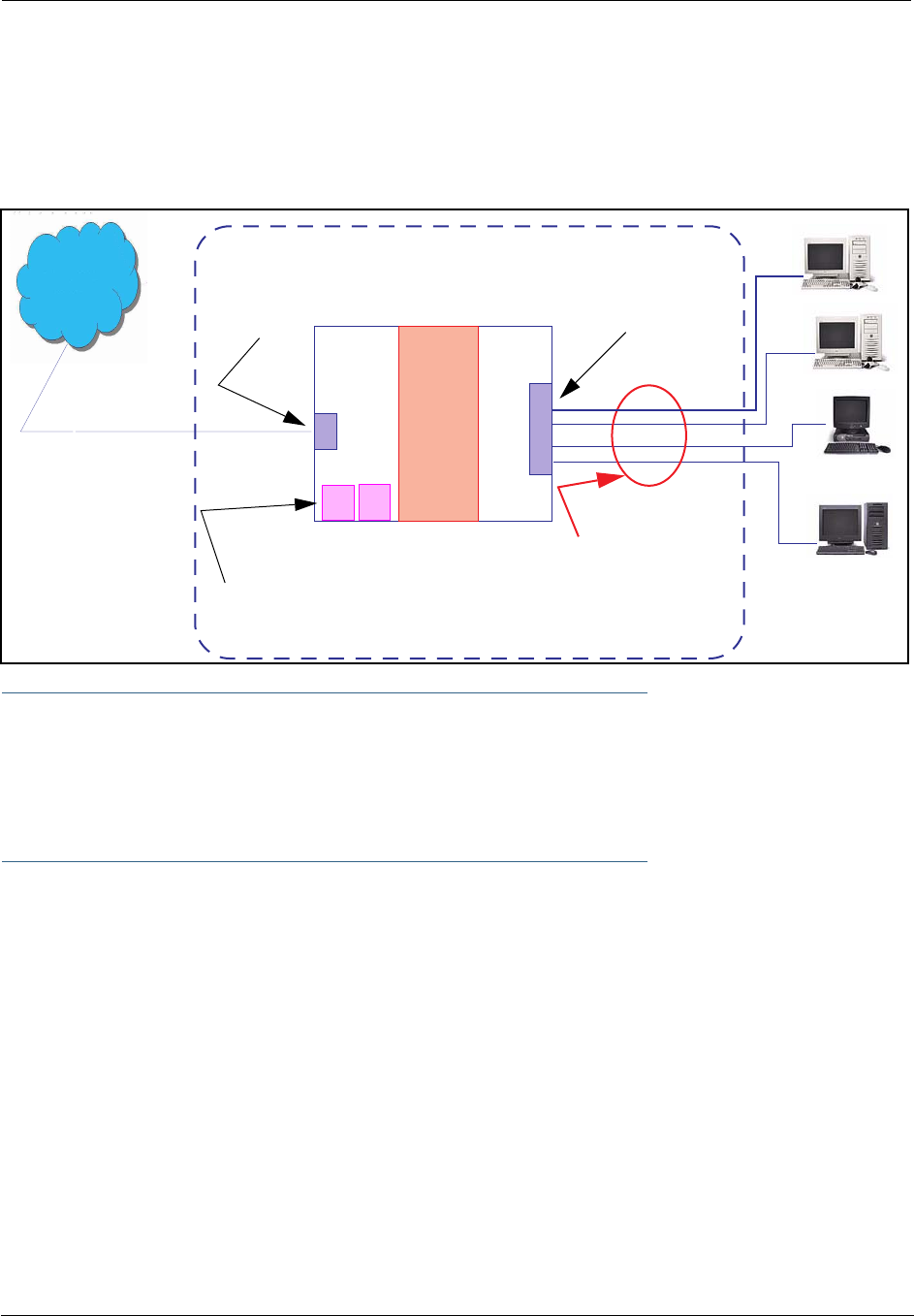
355
•When NAT is OFF, a Motorola Netopia® Gateway acts as a traditional TCP/IP router, all LAN computers/
devices are exposed to the Internet.
A diagram of a typical NAT-enabled LAN follows:
☛ NOTE:
1. The default setting for NAT is ON.
2. Motorola Netopia® uses Port Address Translation (PAT) to implement the NAT facility.
3. NAT Pinhole traffic (discussed below) is always initiated from the WAN side.
Motorola Netopia® Advanced Features for NAT
Using the NAT facility provides effective LAN security. However, there are user applications that require
methods to selectively by-pass this security function for certain types of Internet traffic.
Motorola Netopia® Gateways provide special pinhole configuration rules that enable users to establish
NAT-protected LAN layouts that still provide flexible by-pass capabilities.
Some of these rules require coordination with the unit’s embedded administration services: the internal
Web (HTTP) Port (TCP 80) and the internal Telnet Server Port (TCP 23).
Internal Servers
The internal servers are the embedded Web and Telnet servers of the Gateway. You would change the inter-
nal server ports for Web and Telnet of the Gateway if you wanted to have these services on the LAN using
pinholes or the Default server.
WAN
Interface
LAN
Ethernet
Interface
Motorola Netopia® Gateway
NAT
Internet
Embedded Admin Services:
HTTP-Web Server and Telnet Server Port
NAT-protected
LAN stations
Ethernet

Administrator’s Handbook
356
Pinholes
This feature allows you to:
•Transparently route selected types of network traffic using the port forwarding facility.
FTP requests or HTTP (Web) connections are directed to a specific host on your LAN.
•Setup multiple pinhole paths.
Up to 32 paths are supported
•Identify the type(s) of traffic you want to redirect by port number.
Common TCP/IP protocols and ports are:
See page 82 for How To instructions.
Default Server
This feature allows you to:
•Direct your Gateway to forward all externally initiated IP traffic (TCP and UDP protocols only) to a default
host on the LAN.
•Enable it for certain situations:
Where you cannot anticipate what port number or packet protocol an in-bound application might use.
For example, some network games select arbitrary port numbers when a connection is opened.
When you want all unsolicited traffic to go to a specific LAN host.
Combination NAT Bypass Configuration
Specific pinholes and Default Server settings, each directed to different LAN devices, can be used together.
☛ WARNING:
Creating a pinhole or enabling a Default Server allows inbound access to the specified LAN sta-
tion. Contact your Network Administrator for LAN security questions.
IP-Passthrough
Motorola Netopia® OS now offers an IP passthrough feature. The IP passthrough feature allows a single PC
on the LAN to have the Gateway’s public address assigned to it. It also provides PAT (NAPT) via the same
public IP address for all other hosts on the private LAN subnet.
FTP (TCP 21) telnet (TCP 23)
SMTP (TCP 25) HTTP (TCP 80)
SNMP (TCP 161, UDP 161)
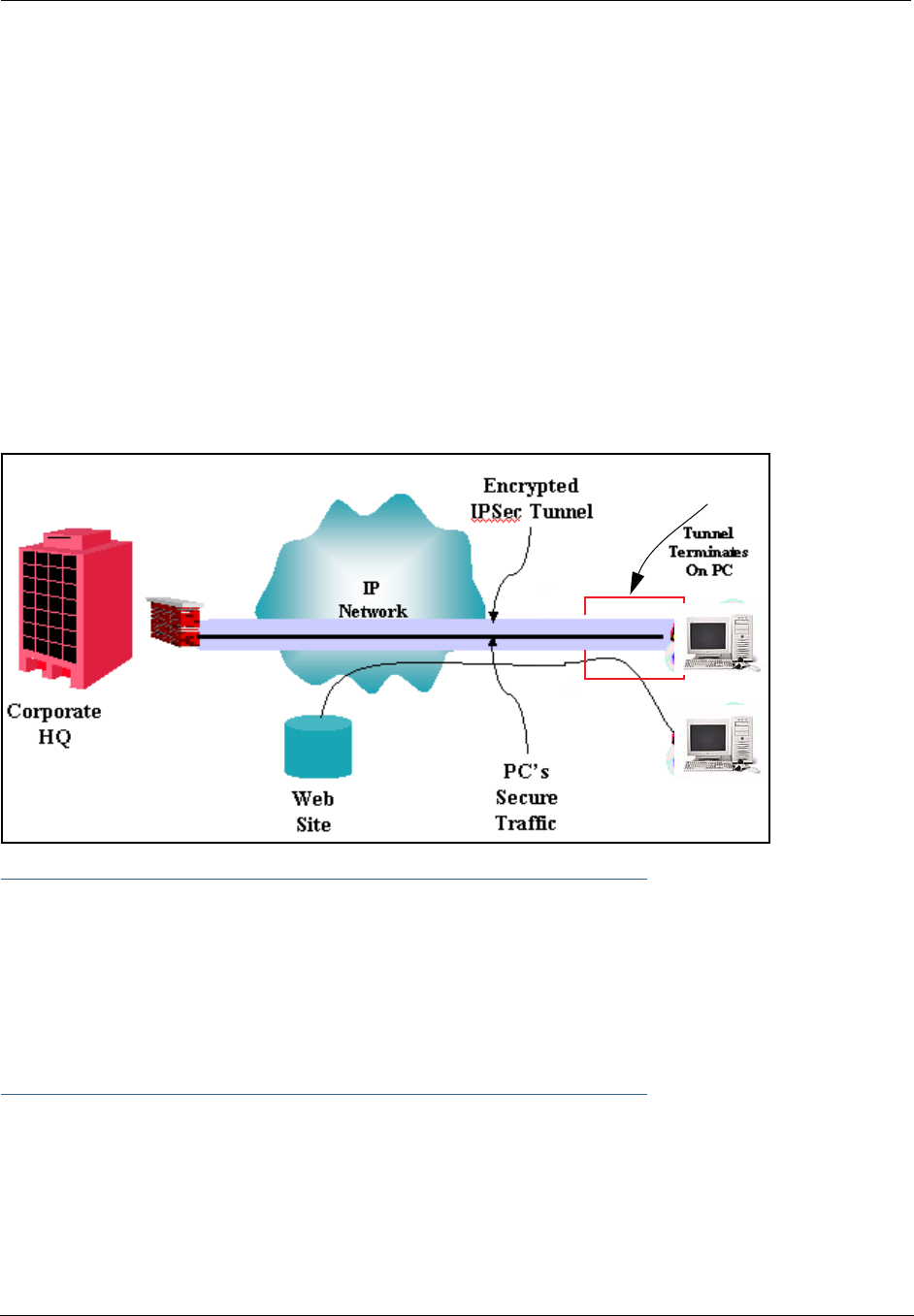
357
VPN IPSec Pass Through
This Motorola Netopia® service supports your independent VPN client software in a transparent manner.
Motorola Netopia® has implemented an Application Layer Gateway (ALG) to support multiple PCs running IP
Security protocols.
This feature has three elements:
1. On power up or reset, the address mapping function (NAT) of the Gateway’s WAN con-
figuration is turned on by default.
2. When you use your third-party VPN application, the Gateway recognizes the traffic from
your client and your unit. It allows the packets to pass through the NAT “protection
layer” via the encrypted IPSec tunnel.
3. The encrypted IPSec tunnel is established “through” the Gateway.
A typical VPN IPSec Tunnel pass through is diagrammed below:
☛ NOTE:
Typically, no special configuration is necessary to use the IPSec pass through feature.
In the diagram, VPN PC clients are shown behind the Motorola Netopia® Gateway and the
secure server is at Corporate Headquarters across the WAN. You cannot have your secure
server behind the Motorola Netopia® Gateway.
When multiple PCs are starting IPSec sessions, they must be started one at a time to allow
the associations to be created and mapped.
VPN IPSec Tunnel Termination
This Motorola Netopia® service supports termination of VPN IPsec tunnels at the Gateway. This permits
tunnelling from the Gateway without the use of third-party VPN client software on your client PCs.
Motorola Netopia®
Gateway

Administrator’s Handbook
358
Stateful Inspection Firewall
Stateful inspection is a security feature that prevents unsolicited inbound access when NAT is disabled. You
can configure UDP and TCP “no-activity” periods that will also apply to NAT time-outs if stateful inspection is
enabled on the interface.
Technical details are discussed in “Expert Mode” on page 39.
SSL Certificate Support
On selected models, you can also install a Secure Sockets Layer (SSL V3.0) certificate from a trusted Cer-
tification Authority (CA) for authentication purposes. If this feature is available on your Gateway, an addi-
tional link will appear in the Install page.
Netopia Embedded Software Version 7.7.4 uses SSL certificates for TR-069 support.
See “Install Certificate” on page 190.
VLANs
Motorola Netopia®'s VGx technology allows a single Motorola Netopia® VGx-enabled broadband gate-
way to act as separate virtual gateways, treating each individual service as a single service "channel." The
VGx-enabled gateway applies specific policies, routing, and prioritization parameters to each service chan-
nel, ensuring delivery of that service to the appropriate peripheral device with the requisite level of QoS and
correct feature sets — making it ideal for delivery of triple play voice, video, and data services.
VGx was developed to ensure that subscribers receive the quality of voice, video, and data services they
expect — to prevent a large data download from causing jittery video or poor voice quality. VGx achieves
this goal by providing superior service segmentation and QoS features obtained by mapping multiple local
virtual local area networks (VLANs) to one or more specific permanent virtual circuits (PVCs) for DSL, or
wide area network VLANs for a fiber network.
Traffic prioritization is determined through the Institute of Electrical Engineering (IEEE) standard 802.1p,
which specifies QoS algorithms to prioritize traffic based on protocol and source. This insures that each
service receives the QoS treatment it requires; for example,
•video is free from latency,
•VoIP service is prioritized to insure aural quality, and
•data is securely and efficiently routed.

359
Index
Symbols
!! command 227
A
Access the GUI 39
Address resolution table 234
Administrative restrictions 264
Administrator password 39, 140, 226
Arguments, CLI 241
ARP
Command 228, 239
ATA configuration 243
Authentication 281
Authentication trap 297
auto-channel mode 303
AutoChannel Setting 57, 303
B
Backup 133
Bridging 246
Broadcast address 259, 261
C
CLI 223
!! command 227
Arguments 241
Command shortcuts 227
Command truncation 240
Configuration mode 240
Keywords 241
Navigating 240
Prompt 227, 240
Restart command 227
SHELL mode 227
View command 242
Command
ARP 228, 239
Ping 230
Telnet 238
Command line interface (see CLI)

Administrator’s Handbook
360
Community 297
Compression, protocol 280
Concurrent Bridging/Routing 105, 247
CONFIG
Command List 225
Configuration mode 240
D
D. port 167
Default IP address 39
denial of service 340
designing a new filter set 169
DHCP 248
DHCP filtering 252
DHCP lease table 231
DHCP option filtering 252
DHCP/PPPoE/PPPoA Autosensing 68
Diagnostic log 231, 235
Level 298
Diagnostics 353
DNS 255
DNS Proxy 353
Documentation conventions 15
Domain Name System (DNS) 255
DSL Forum settings 321
E
Echo request 280
echo-period 280
Embedded Web Server 353
Ethernet address 246
Ethernet statistics 231
F
Feature Keys
Obtaining 187
filter
parts 165
parts of 165
filter priority 164
filter set
adding 171
display 167

361
filter sets
adding 171
defined 163
deleting 175
disadvantages 163
using 171
filtering example #1 167
filters
actions a filter can take 165
adding to a filter set 172
defined 163
deleting 175
input 172
modifying 175
output 172
using 170, 171
viewing 175
firewall 235
FTP 278
H
Hardware address 246
hijacking 340
Hop count 277
HTTP traffic 286
I
ICMP Echo 230
IGMP 100
IGMP Snooping 101, 257
Install 182
Install Certificate 190
IP address 259, 261
Default 39
IP interfaces 234
IP routes 235
IP Subnets 50
IPMap table 235
IPSec Tunnel 234
K
Keywords, CLI 241

Administrator’s Handbook
362
L
LAN Host Discovery Table 235
latency 177
LCP echo request 280
Link
Install Software 182
Quickstart 47, 49, 67
Local Area Network 352
Location, SNMP 297
Log 235
Logging in 226
lost echoes 280
M
Magic number 280
Memory 235
Metric 277
multi-cast forwarding 260, 283
Multiple SSIDs 59
multiple subnets 50
Multiple Wireless SSIDs
Wireless 59, 303
N
Nameserver 255
NAT 264, 278, 354
Traffic rules 90
NAT Default Server 356
Netmask 262
Network Address Translation 354
Network Test Tools 353
NSLookup 353
O
set upnp option 321
Operating Mode
Wireless 56, 303
P
PAP 351
Password 140
Administrator 39, 140, 226
User 39, 140, 226

363
persistent-log 299
Ping 353
Ping command 230
Pinholes 278, 356
Planning 82
policy-based routing 177
Port authentication 281
port number
comparisons 166
port numbers 165
Port renumbering 286
PPP 240
PPPoE 351
PPPoE with IPoE 71, 73
Primary nameserver 255
Prompt, CLI 227, 240
Protocol compression 280
Q
qos max-burst-size 245
qos peak-cell-rate 245
qos service-class 245
qos sustained-cell-rate 245
quality of service 165, 177
R
Restart 232
Restart command 227
Restart timer 280
Restrictions 264
RIP 261, 262
Routing Information Protocol (RIP) 261, 262
rtsp-passthrough 276
S
Secondary nameserver 255
Secure Sockets Layer 190
Security
filters 163
Security log 180
Session Initiation Protocol 120, 316
Set bncp command 245, 246
Set bridge commands 247

Administrator’s Handbook
364
Set DMT commands 254
Set dns commands 255
Set ip static-routes commands 276
Set ppp module port authentication command 281
Set preference more command 285
Set preference verbose command 285
set security state-insp 292
Set servers command 286
Set servers telnet-tcp command 286
Set snmp sysgroup location command 297
Set snmp traps authentification-traps ip-address command 297
Set system diagnostic-level command 298
Set system heartbeat command 300
Set system name command 298
Set system NTP command 300
Set system password command 299
set system syslog 301
Set wireless option command 303
Set wireless user-auth option command 309
SHELL
Command Shortcuts 227
Commands 227
Prompt 227
SHELL level 240
SHELL mode 227
show config 232
Show ppp 240
Simple Network Management Protocol (SNMP) 297
SIP 120, 316
sip-passthrough 276
SMTP 278
SNMP 98, 278, 297
SNMP Notify Type settings 297
src. port
167
SSL certificates 190
Stateful Inspection 154
stateful inspection 235
Static route 276
Step mode 242
Subnet mask 262
Subnets 50
subnets
multiple 50
Syslog 125

365
System contact, SNMP 297
System diagnostics 298
system idle-timeout 299
T
Telnet 226, 278
Telnet command 238
Telnet traffic 286
TFTP 278
TFTP server 229
Toolbar 43
TOS bit 165, 177
TraceRoute 218, 354
Trap 297
Trivial File Transfer Protocol 229
Truncation 240
U
UPnP 102
User name 226
User password 39, 140, 226
V
set atm 245
View command 242
view config 238
VLAN ID 111
VLAN Settings 311
VLANs 107
Voice-over-IP 120, 316
VoIP 120, 316
VPN
IPSec Pass Through 357
IPSec Tunnel Termination 357
W
Weighted Fair Queue 273
weighted fair queuing 271
Wide Area Network 351
WiFi Multimedia 62
Wireless 53


367
Motorola Netopia® 2200-, 3300- or 7000-series
Motorola, Inc.
6001 Shellmound Street
Emeryville, CA 94608
August 2, 2007

Administrator’s Handbook
368