ARRIS 2W3801HGV Wireless 802.11g VDSL Residential Gateway User Manual 3801HGV
Pace Americas Wireless 802.11g VDSL Residential Gateway 3801HGV
UserManual.wiki
>
ARRIS
>
2W3801HGV User Manual
>
User's Guide
Contents
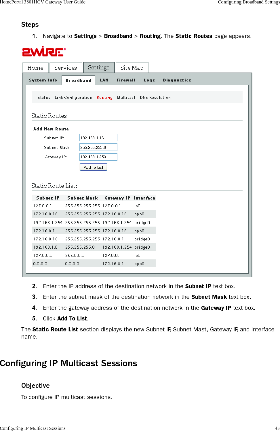
1.
User's Guide
2.
Regulatory insert
User's Guide
Navigation menu
Upload a User Manual
Namespaces
Wiki Guide
HTML
PDF
Info
Views
User Manual
Discussion / Help
Navigation
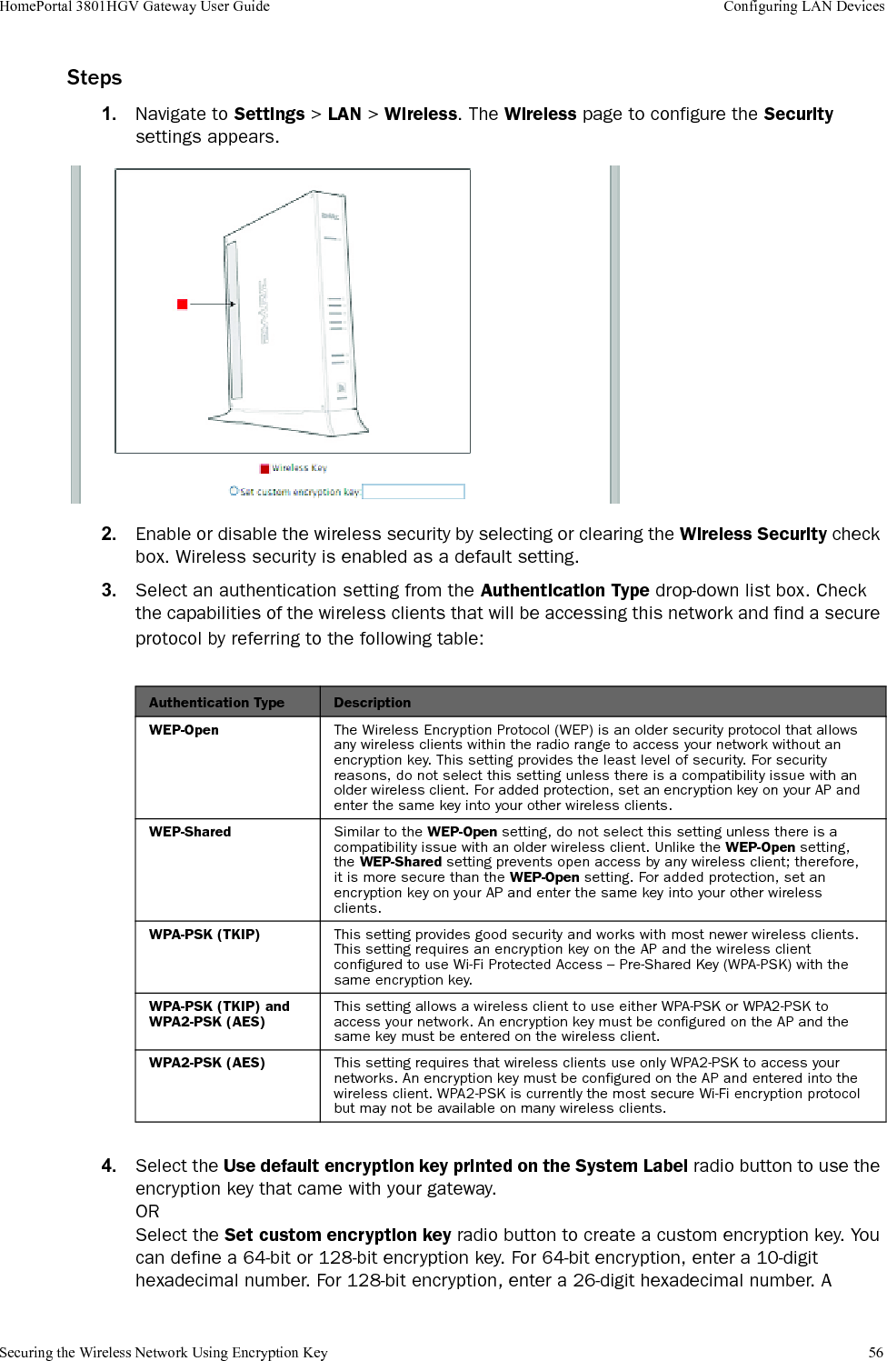
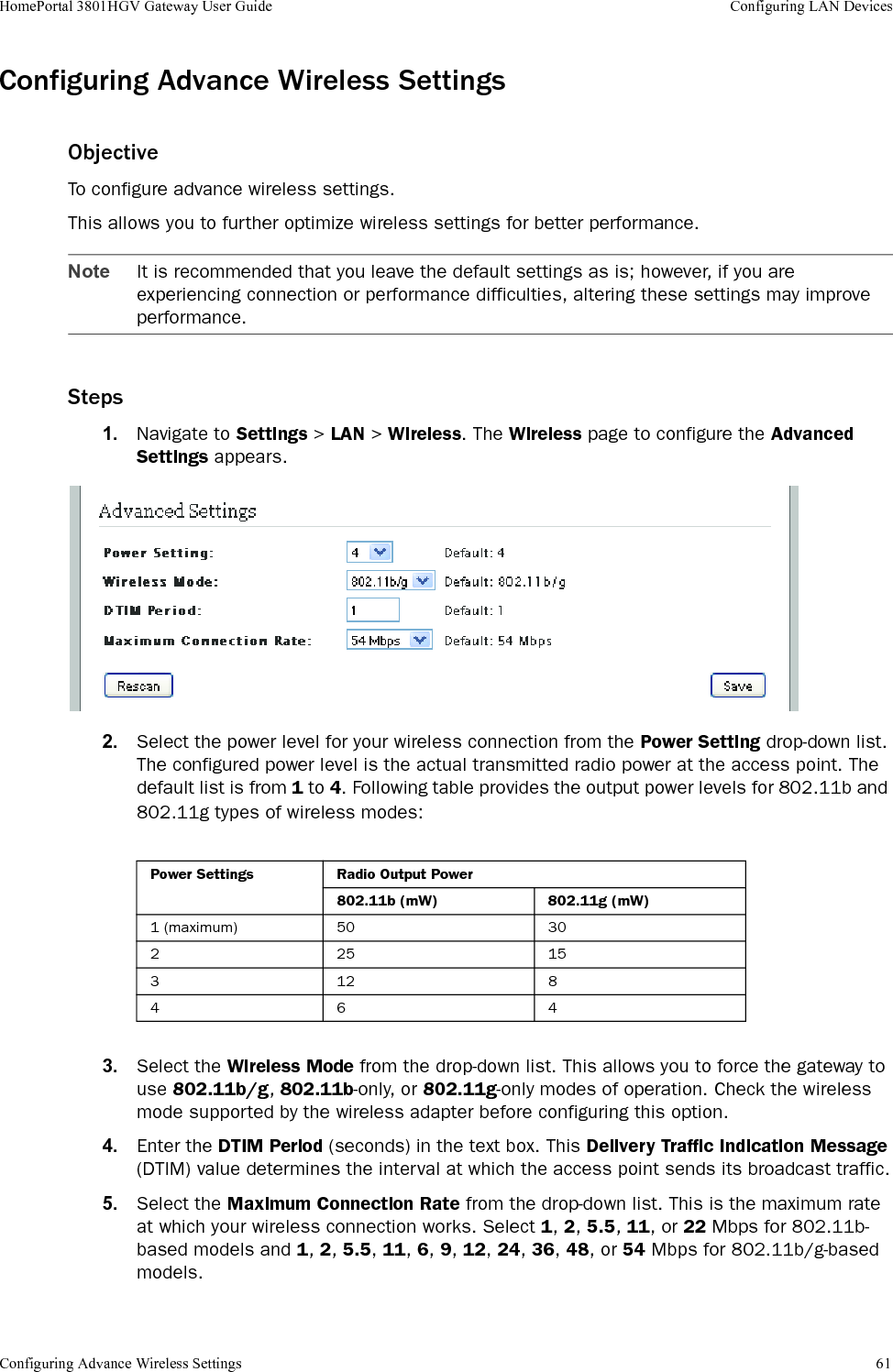
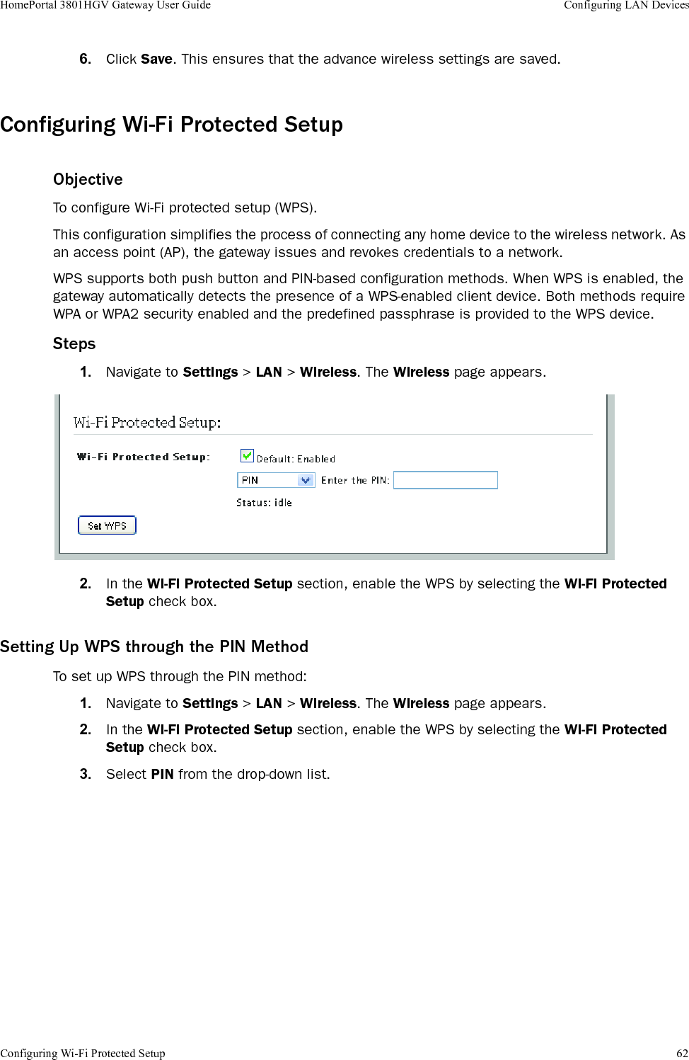
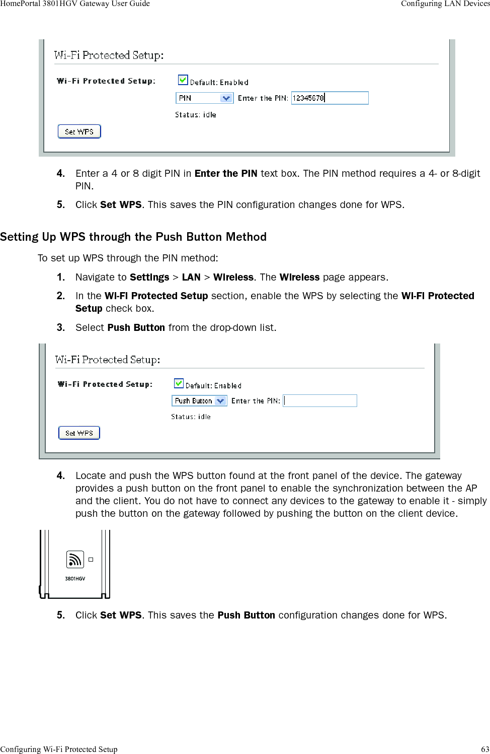
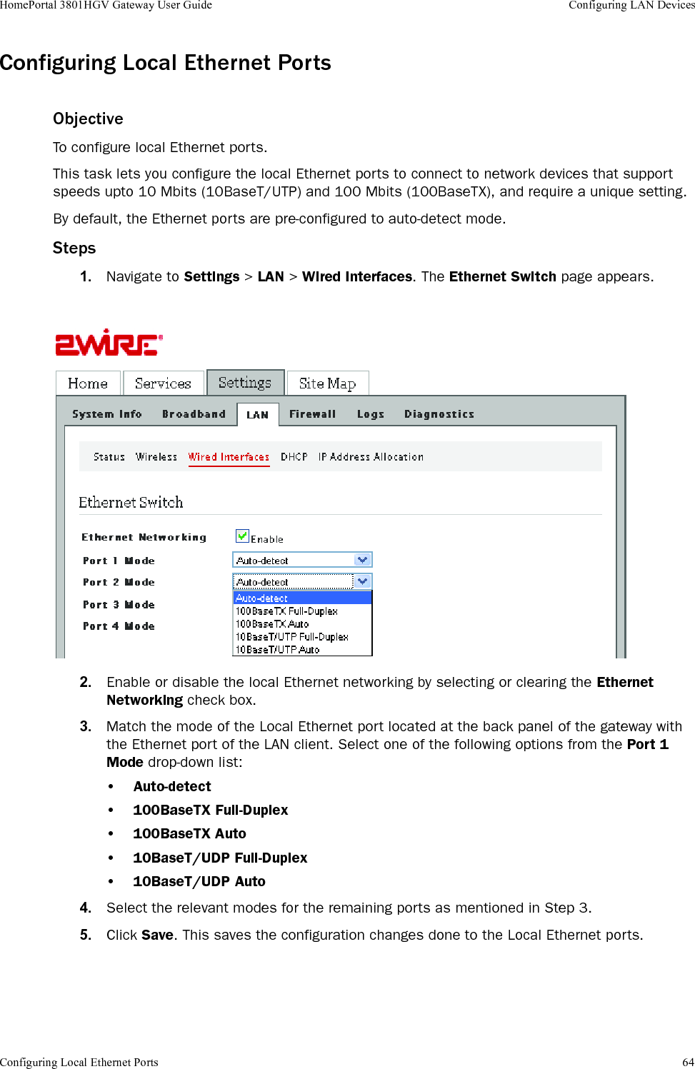
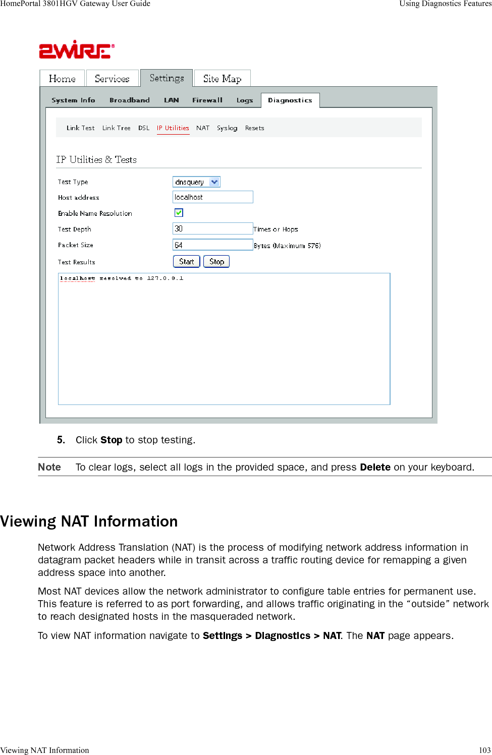
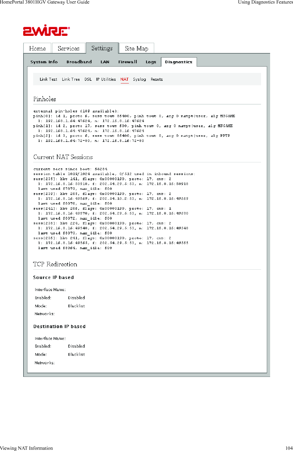
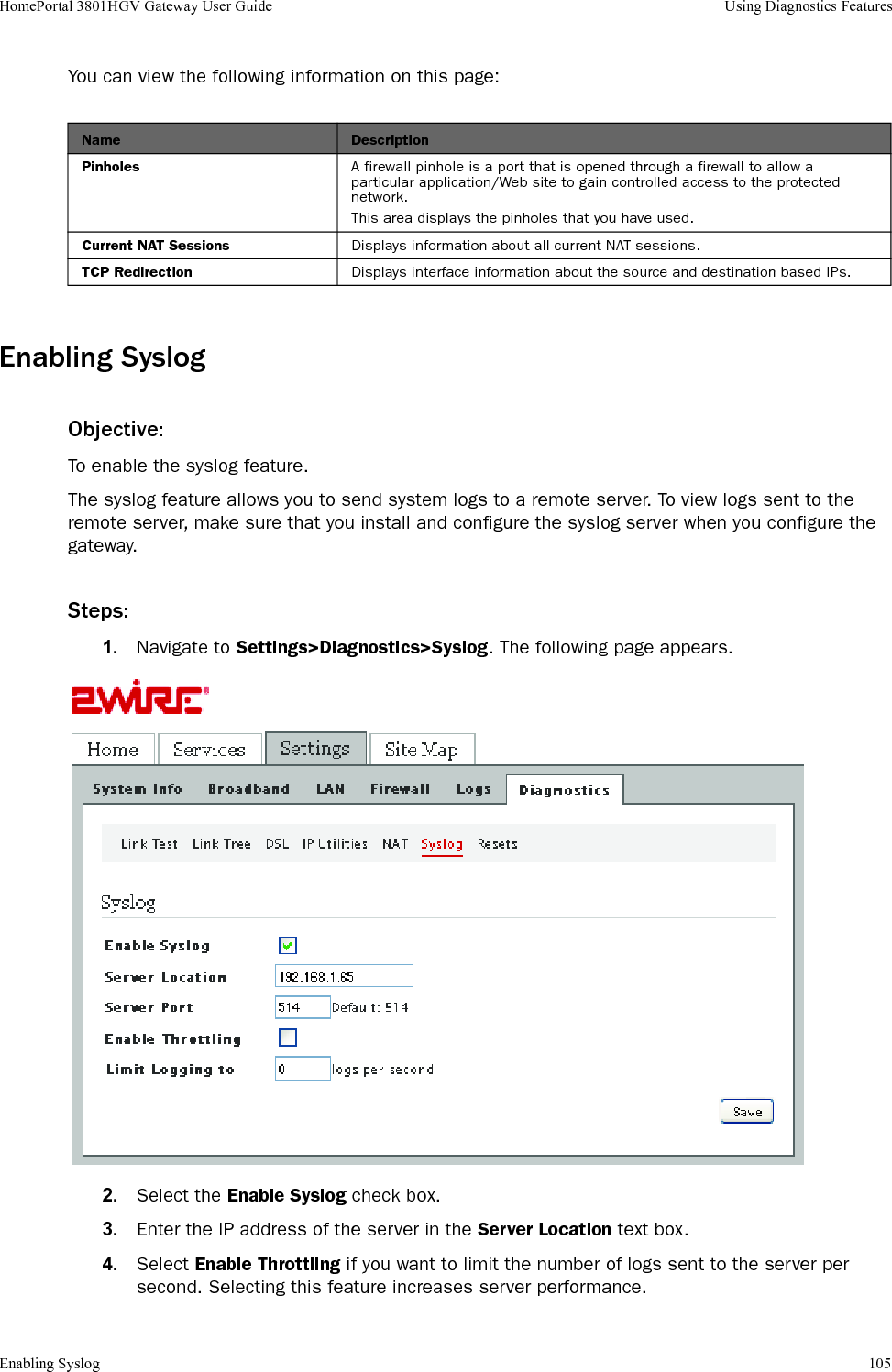
![50CHAPTER 9Configuring LAN DevicesNOTE TO REVIEWER: [JIRA 1515: ...Unable to determine the steps to set up multiple SSIDs and associated information on the UI of 3801HGV.].Please provide the necessary info to document this. How do we configure multiple SSIDs through the UI?This chapter provides information about the tasks you can perform in the LAN tab. Following are the links under the LAN tab, and associated tasks:• Status•Viewing LAN Status on page 51• Wireless•Setting Up Wireless Network on page 53•Securing the Wireless Network Using Encryption Key on page 55•Securing the Wireless Network Using MAC Filtering on page 57•Configuring Advance Wireless Settings on page 61•Configuring Wi-Fi Protected Setup on page 62• Wired Interfaces•Configuring Local Ethernet Ports on page 64•Configuring HomePNA 3.1 on page 65•Viewing HomePNA Status on page 66•DHCP•Configuring DHCP on page 66• IP Address Allocation•Allocating IP Addresses on page 69](https://usermanual.wiki/ARRIS/2W3801HGV.User-s-Guide/User-Guide-1233843-Page-58.png)
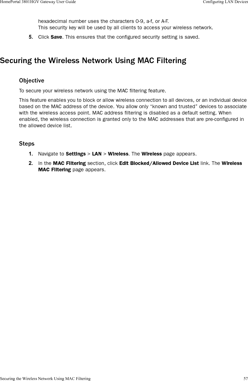
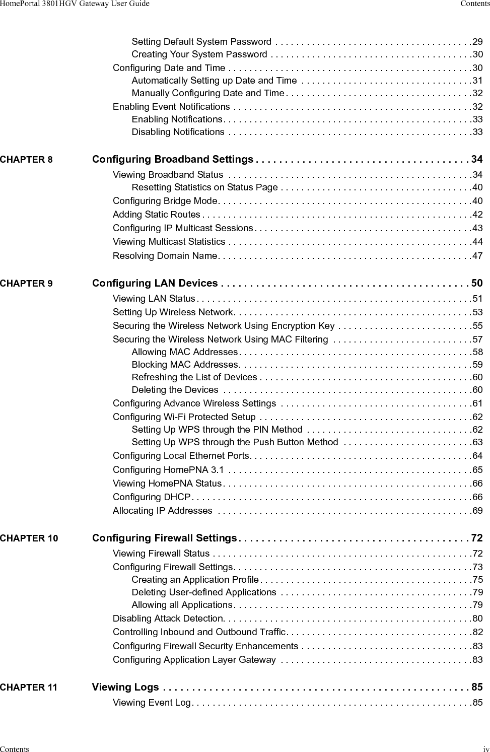
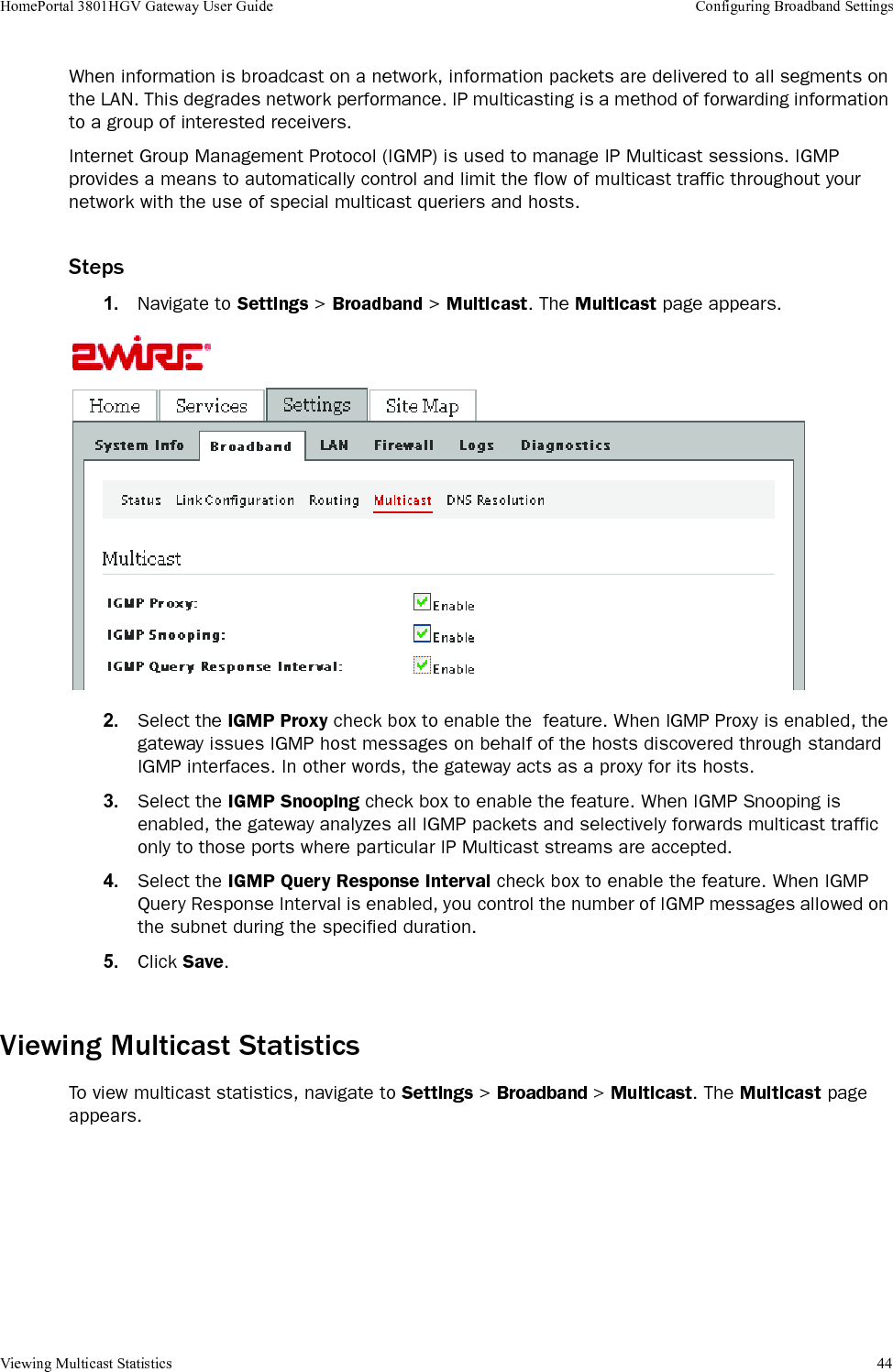
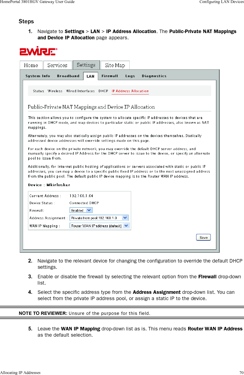
![Securing the Wireless Network Using MAC Filtering 59HomePortal 3801HGV Gateway User Guide Configuring LAN DevicesSteps1. Navigate to Settings > LAN > Wireless. The Wireless page to configure the MAC filtering settings appears. 2. Add the MAC address of the device in the Enter MAC address text box.3. Click Add To List. This populates the MAC address in the Allowed Devices pane.Blocking MAC AddressesObjectiveThis feature block wireless connection to all devices, or an individual device based on the MAC address of the device. Steps1. Navigate to Settings > LAN > Wireless. The Wireless page appears.2. In the MAC Filtering section, click Edit Blocked/Allowed Device List link. The Wireless MAC Filtering page appears.3. Select the device you want to block from the Allowed Devices pane.Note To select multiple addresses, hold down the [Shift] or [Ctrl] keys while making your selections. Using the [Shift] key lets you make your selections in a contiguous order, while the [Ctrl] key selects the groups in a random order.4. Click >>. This polulates the MAC address in the Blocked Devices pane.](https://usermanual.wiki/ARRIS/2W3801HGV.User-s-Guide/User-Guide-1233843-Page-67.png)
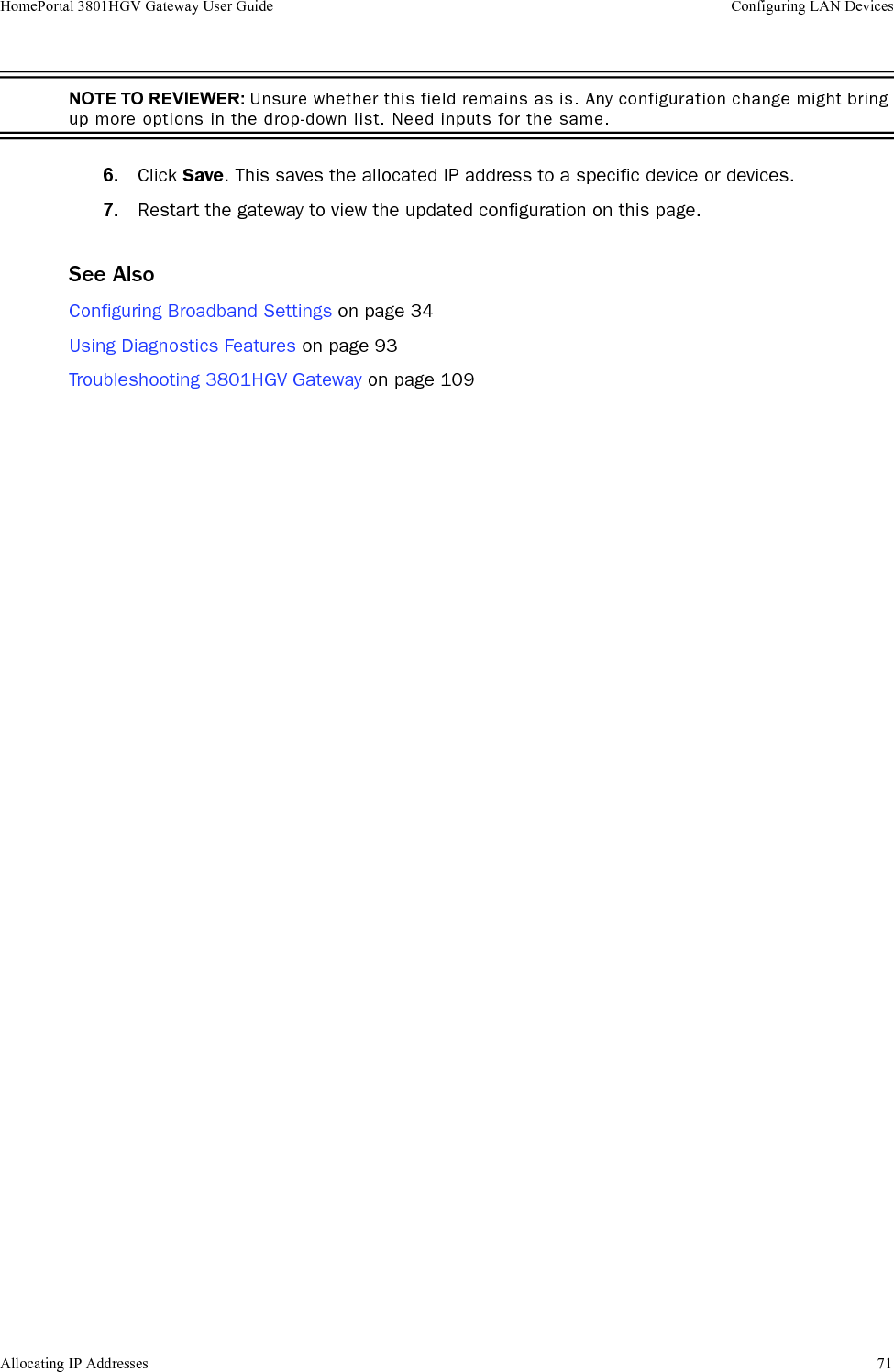
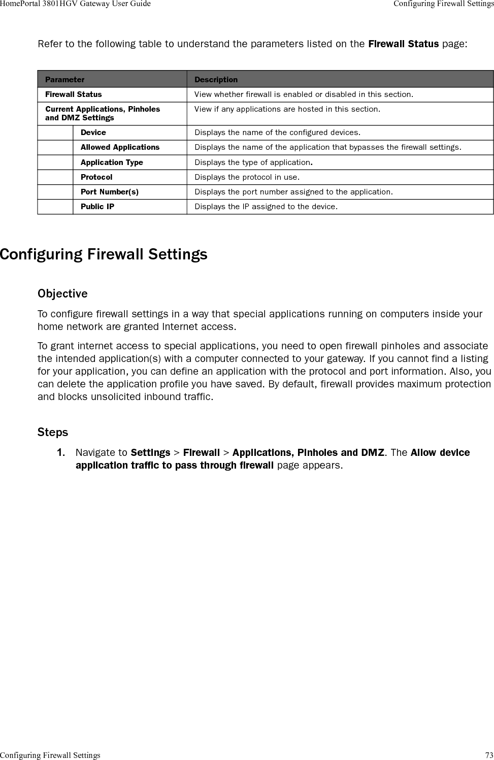
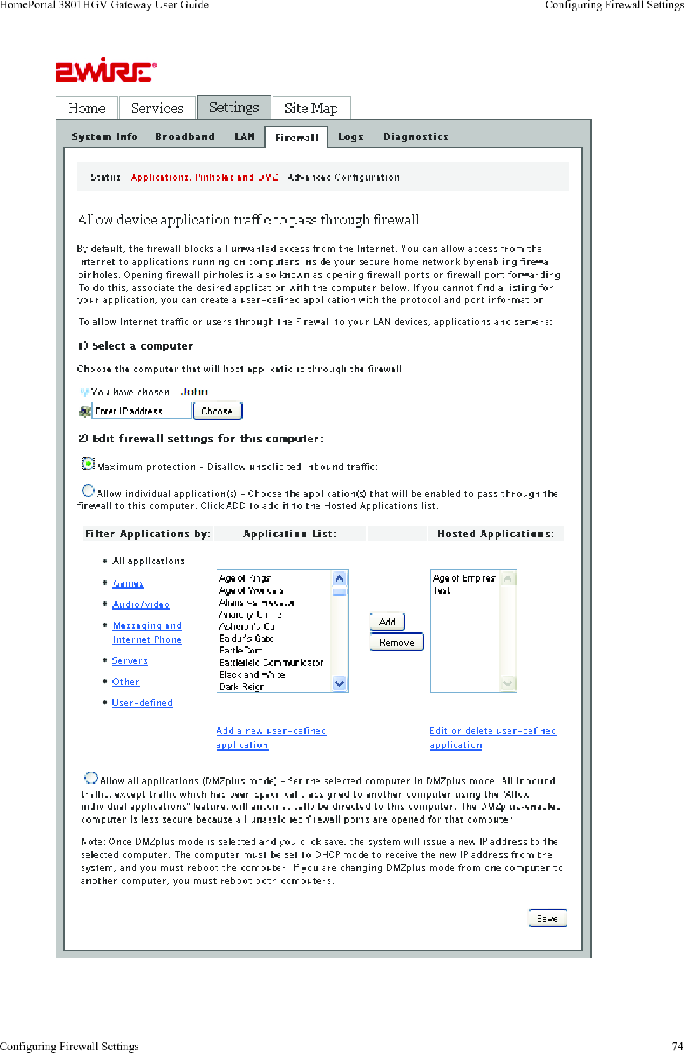
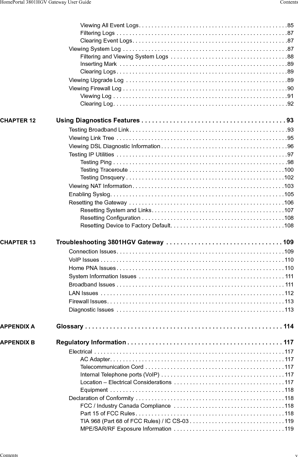
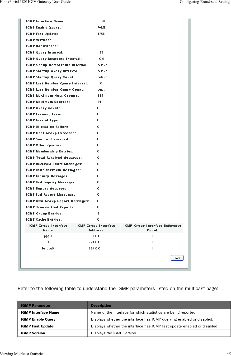
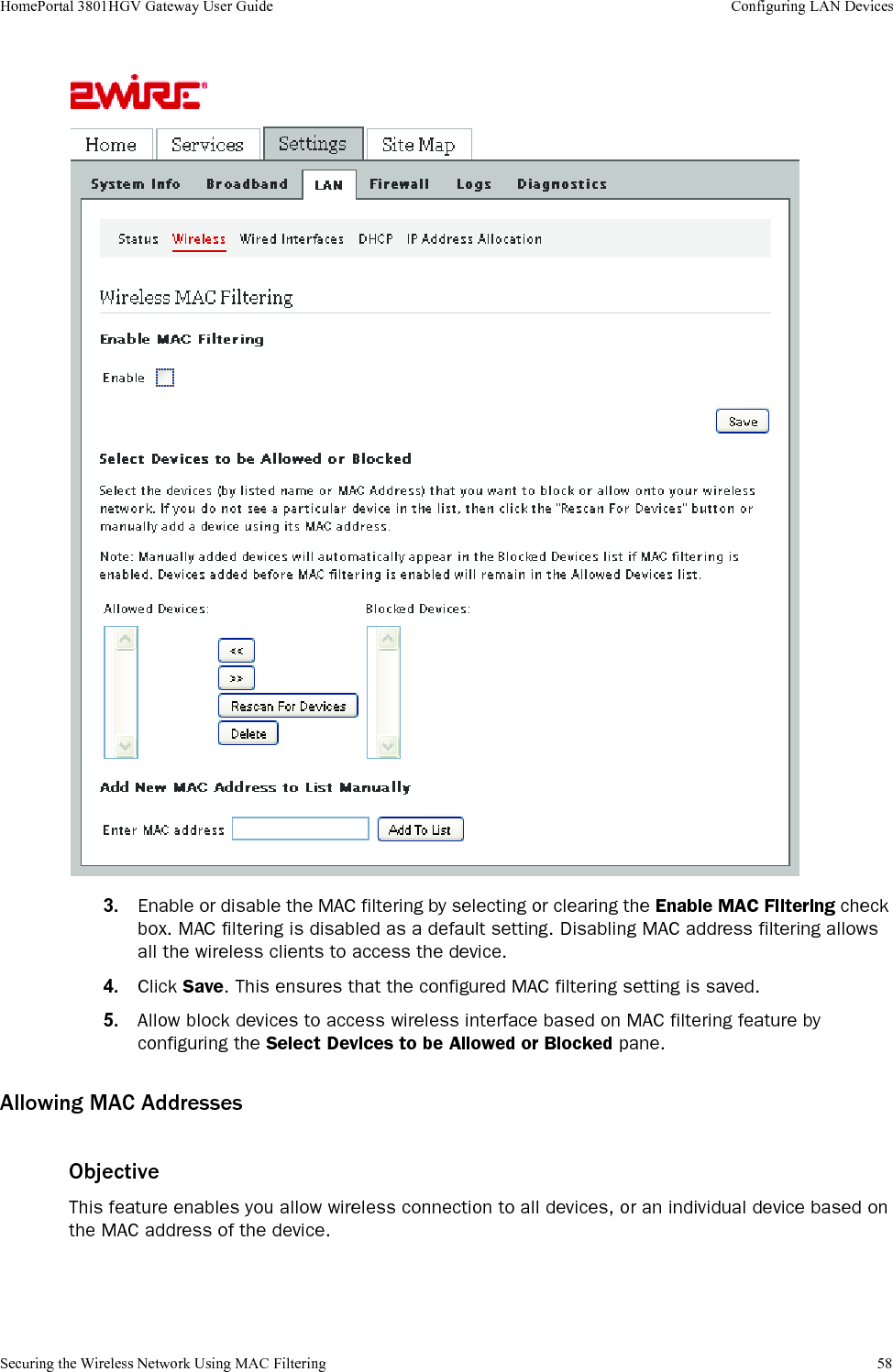
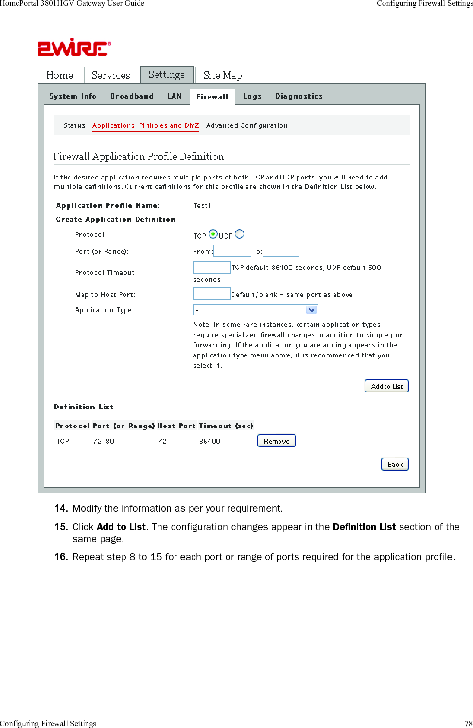
![Configuring Firewall Settings 75HomePortal 3801HGV Gateway User Guide Configuring Firewall Settings2. Select the computer where you want to host the application(s) in the Select a computer section. When you host an application for a computer on your network, it implies that you are scaling down the firewall security levels for that application to be accessible on the specified computer.3. Select the Allow individual application(s) radio button.Note If the computer you want to select is not listed, you can still select it as long as it is on the same network, and you know its IP address. Enter the IP address of that computer, and then click Choose.4. Filter the application list by selecting the category from the Filter Applications by bulleted list. Your selection is displayed in the Application List list box.Note To select multiple applications, hold down the [Shift] or [Ctrl] keys while making your selections. Using the [Shift] key lets you make your selections in a contiguous order while the [Ctrl] key selects the groups in a random order.5. Click Add. The application appears in the Hosted Applications list box.Note To remove a hosted application, select it in the Hosted Applications list box, and click Remove.Creating an Application ProfileTo create an application profile that bypasses the firewall settings:1. Navigate to Settings > Firewall > Applications, Pinholes and DMZ. The Allow device application traffic to pass through firewall page appears.2. Click Add a new user-defined application in the Edit firewall settings for this computer section. This lets you create an application profile that is not included in the application list. An application profile configures the gateway firewall to let the application-specific data pass through. The Firewall Application Profile Definition page appears.](https://usermanual.wiki/ARRIS/2W3801HGV.User-s-Guide/User-Guide-1233843-Page-83.png)

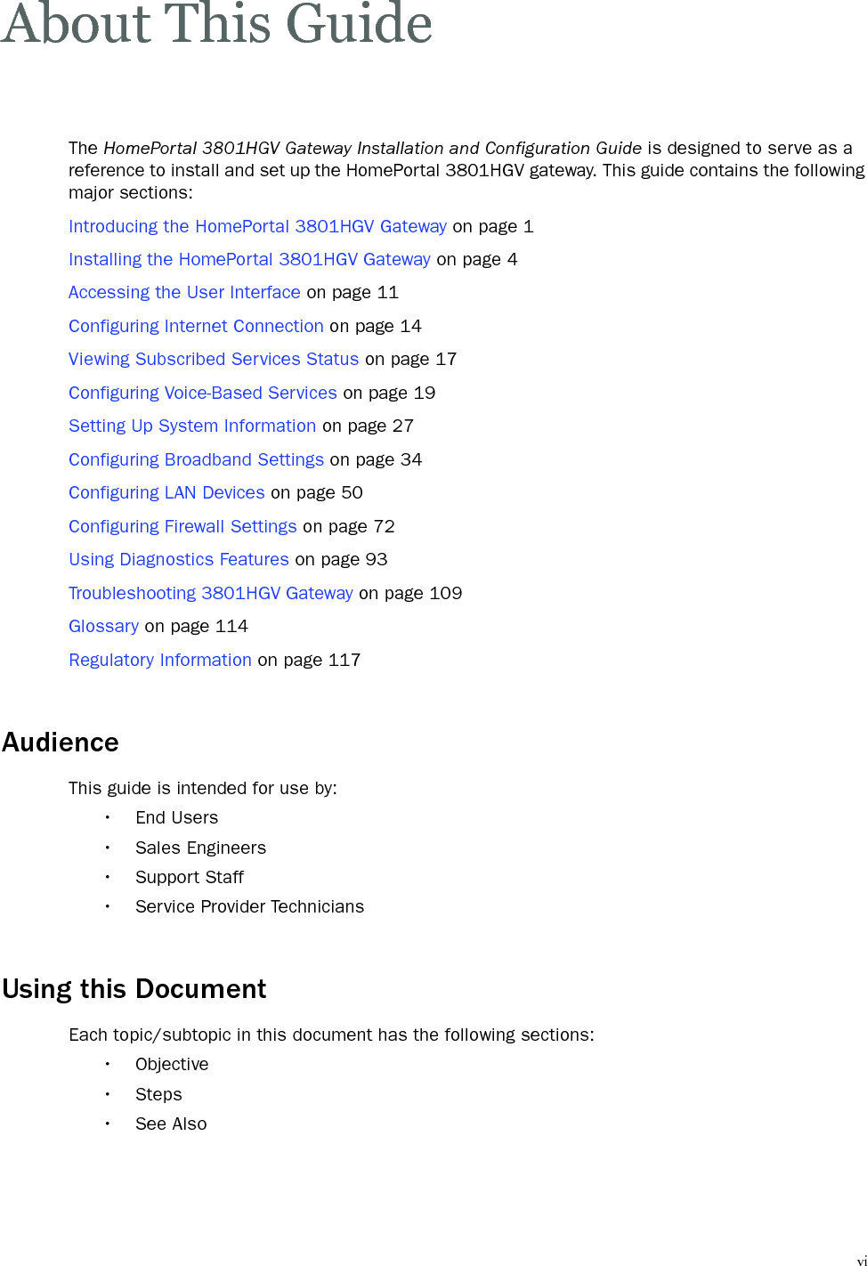
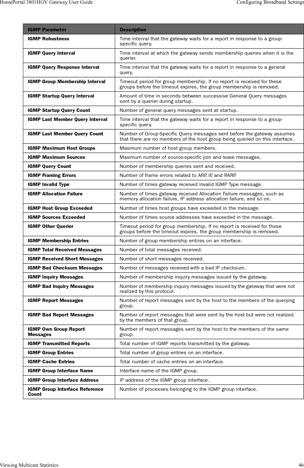
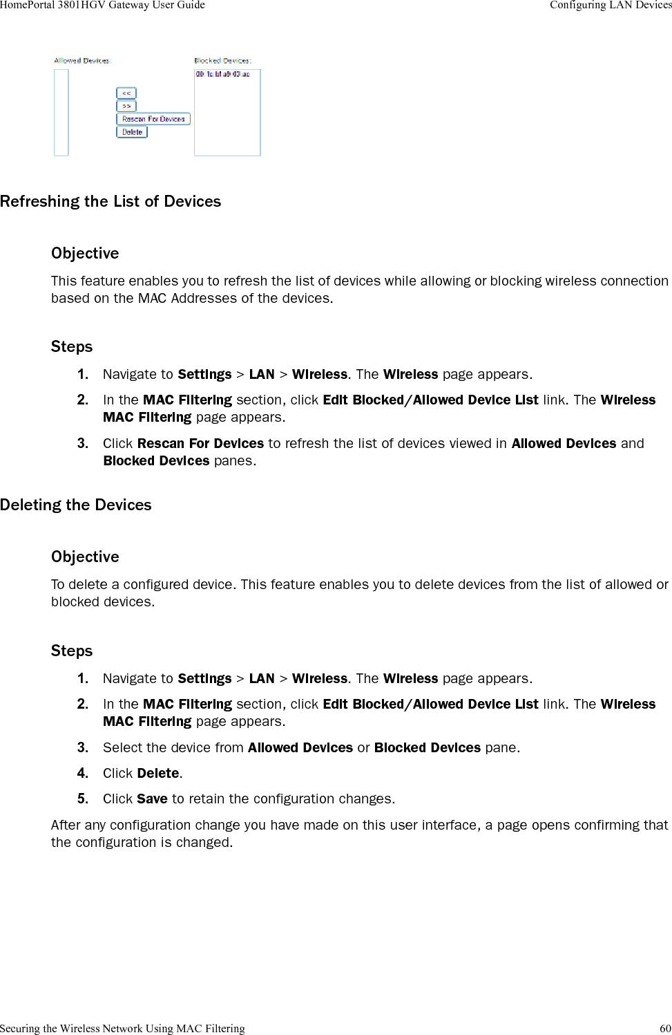
![Declaration of Conformity 118HomePortal 3801HGV Gateway User Guide Regulatory InformationEquipmentRepairsDo not, under any circumstances, attempt any service, adjustments, or repairs on this equipment. Instead, contact your local 2Wire distributor or service provider for assistance. Failure to comply may void the product warranty.Location – Environmental ConsiderationsDo not plug the AC/DC power adapter into an outdoor outlet or operate the residential gateway outdoors. It is not waterproof or dustproof, and is for indoor use only. Any damage to the unit from exposure to rain or dust may void your warranty.Do not use the residential gateway where there is high heat, dust, humidity, moisture, or caustic chemicals or oils. Keep the gateway away from direct sunlight and anything that radiates heat, such as a stove or a motor.Declaration of ConformityFCC / Industry Canada ComplianceThis device has been tested and certified as compliant with the regulations and guidelines set forth in the Federal Communication commission - FCC part 15, FCC part 68 and Industry Canada - ICES003 and RSS-210 Radio and telecommunication regulatory requirements / Le présent materiel est conforme aux specifications techniques applicables d’Industrie Canada. Cet appareil numérique de la classe [*] est conforme à la norme NMB-003 du Canada.Manufacturer: 2Wire, Inc.Model(s): RG3801HGV-00Part 15 of FCC RulesThis device complies with Part 15 of the FCC Rules. Operation is subject to the following two conditions:1. This device may not cause harmful interference, and2. This device must accept any interference received, including interference that may cause undesired operation.This equipment has been tested and found to comply with the limits for a Class B digital device, pursuant to part 15 of the FCC Rules. These limits are designed to provide reasonable protection against harmful interference in a residential installation. This equipment generates, uses and can radiate radio frequency energy and, if not installed and used in accordance with the instructions, may cause harmful interference to radio communications. However, there is no guarantee that interference will not occur in a particular installation. If this equipment does cause harmful interference to radio or television reception, which can be determined by turning the equipment off and on, the user is encouraged to try to correct the interference by one or more of the following measures:• Reorient or relocate the receiving antenna• Increase the separation between the equipment and receiver](https://usermanual.wiki/ARRIS/2W3801HGV.User-s-Guide/User-Guide-1233843-Page-126.png)