ARRIS 2W4100N 802.11b/g/n ADSL RESIDENTIAL GATEWAY User Manual
Pace Americas 802.11b/g/n ADSL RESIDENTIAL GATEWAY
UserManual.wiki
>
ARRIS
>
2W4100N User Manual
Installation Guide
Navigation menu
Upload a User Manual
Namespaces
Wiki Guide
HTML
PDF
Info
Views
User Manual
Discussion / Help
Navigation
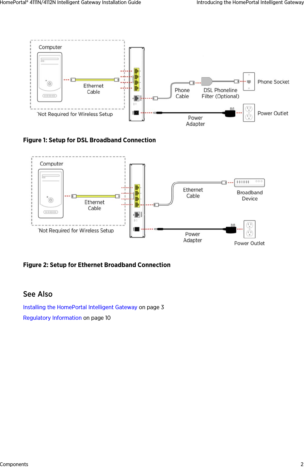
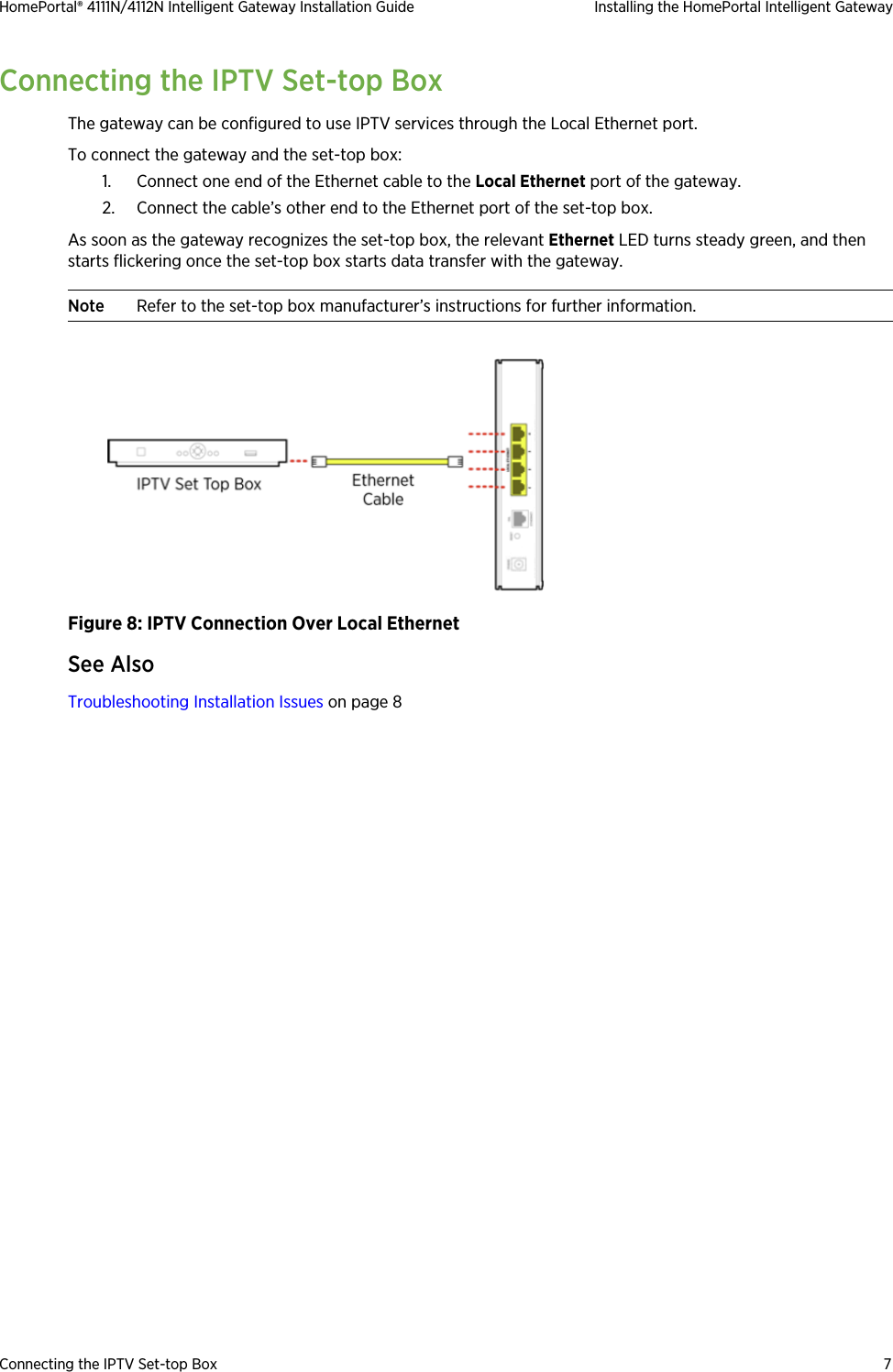
![Declaration of Conformity 11HomePortal® 4111N/4112N Intelligent Gateway Installation Guide Regulatory InformationLocation – Environmental ConsiderationsDo not plug the AC/DC power adapter in an outdoor outlet or operate the gateway outdoors. It is not waterproof or dustproof, and is for indoor use only. Any damage to the unit from exposure to rain or dust may void your warranty.Do not expose the residential gateway to high heat, dust, humidity, moisture, caustic chemicals, or oils. Keep the gateway away from direct sunlight and any material that radiates heat, such as a stove or a motor.Declaration of ConformityFCC / Industry Canada ComplianceThis device has been tested and certified as compliant with the regulations and guidelines set forth in the Federal Communication commission - FCC part 15, FCC part 68 and Industry Canada - ICES003 and RSS-210 Radio and telecommunication regulatory requirements.Le présent materiel est conforme aux specifications techniques applicables d’Industrie Canada. Cet appareil numérique de la classe [*] est conforme à la norme NMB-003 du Canada.Manufacturer: 2Wire, Inc. DBA Pace AmericasModel(s): 4111N, 4112NPart 15 of FCC RulesThis device complies with Part 15 of the FCC Rules. The operation of this device is subject to the following two conditions:1. This device may not cause harmful interference.2. This device must accept any interference received, including interference that may cause undesired operation.This equipment has been tested and found to comply with the limits for a Class B digital device, pursuant to part 15 of the FCC Rules. These limits are designed to provide reasonable protection against harmful interference in a residential installation. This equipment generates, uses and can radiate radio frequency energy and, if not installed and used in accordance with the instructions, may cause harmful interference to radio communications. However, there is no guarantee that interference will not occur in a particular installation. If this equipment does cause harmful interference to radio or television reception, which can be determined by turning the equipment off and on, the user is encouraged to try to correct the interference by one or more of the following measures:• Reorient or relocate the receiving antenna• Increase the separation between the equipment and receiver• Connect the equipment into an outlet on a circuit different from that to which the receiver is connected• Consult the dealer or an experienced radio/TV technician for helpTIA 968 (Part 68 of FCC Rules) / IC CS-03This equipment complies with the Telecommunication Industry Association TIA-968 (FCC part 68) and Industry Canada CS-03 Telecommunication requirements. On the product is a label that contains, among other information, the IC and FCC registration number and ringer equivalence number (REN) for this equipment. If requested, this information may be provided to the telephone company.mChanges or modifications not expressly approved by the party responsible for compliance could void your authority to operate this equipment.](https://usermanual.wiki/ARRIS/2W4100N/User-Guide-1405635-Page-16.png)