ARRIS 2WI38HG Wireless LAN Gateway User Manual i38HG UG
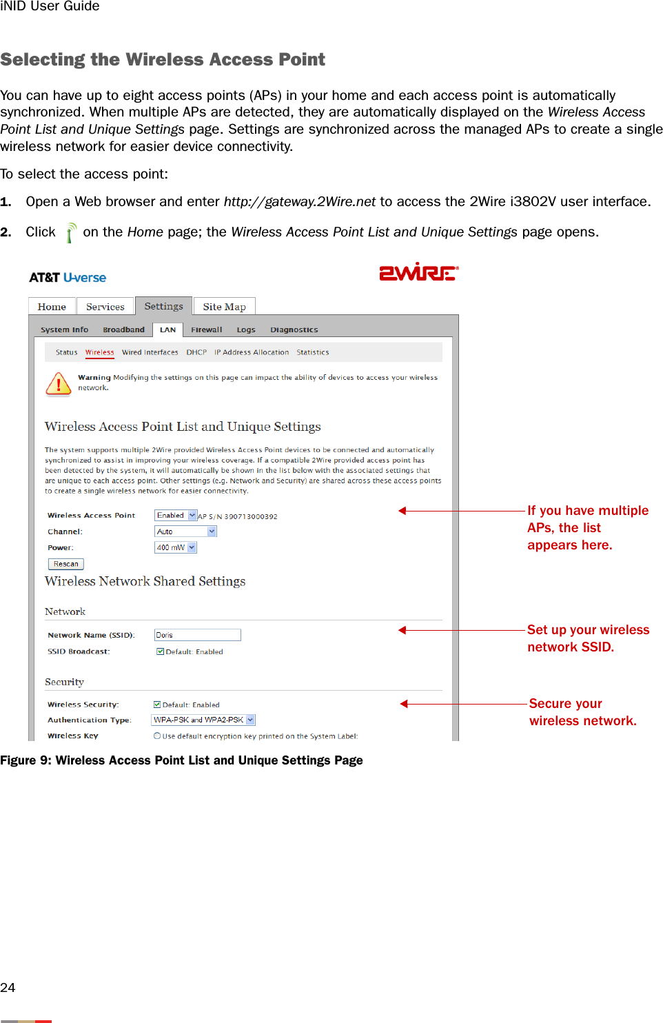
Pace Americas Wireless LAN Gateway i38HG UG
UserManual.wiki
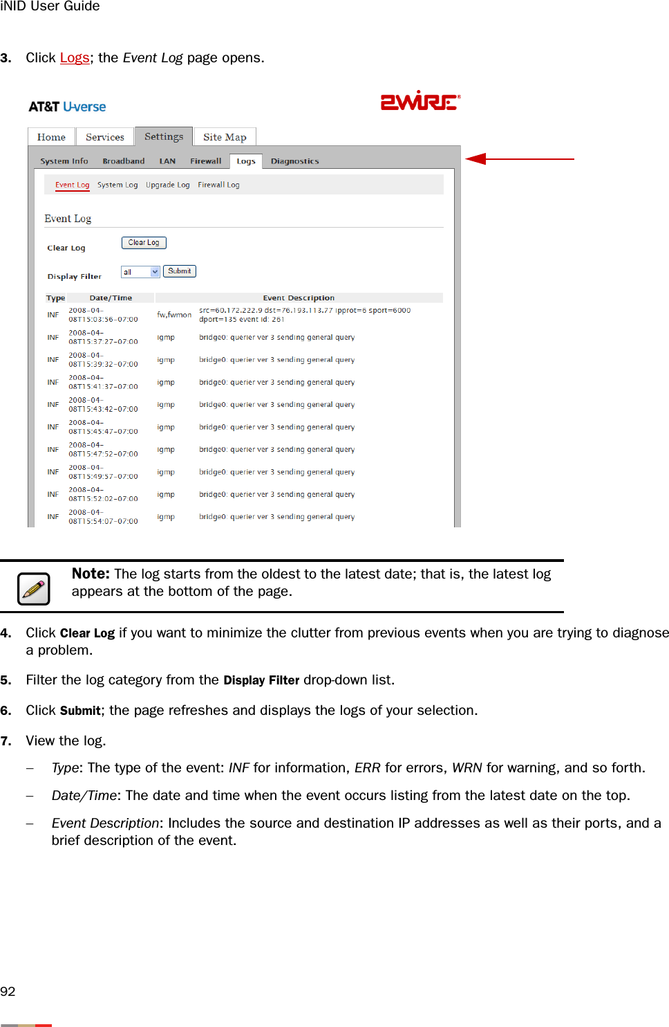
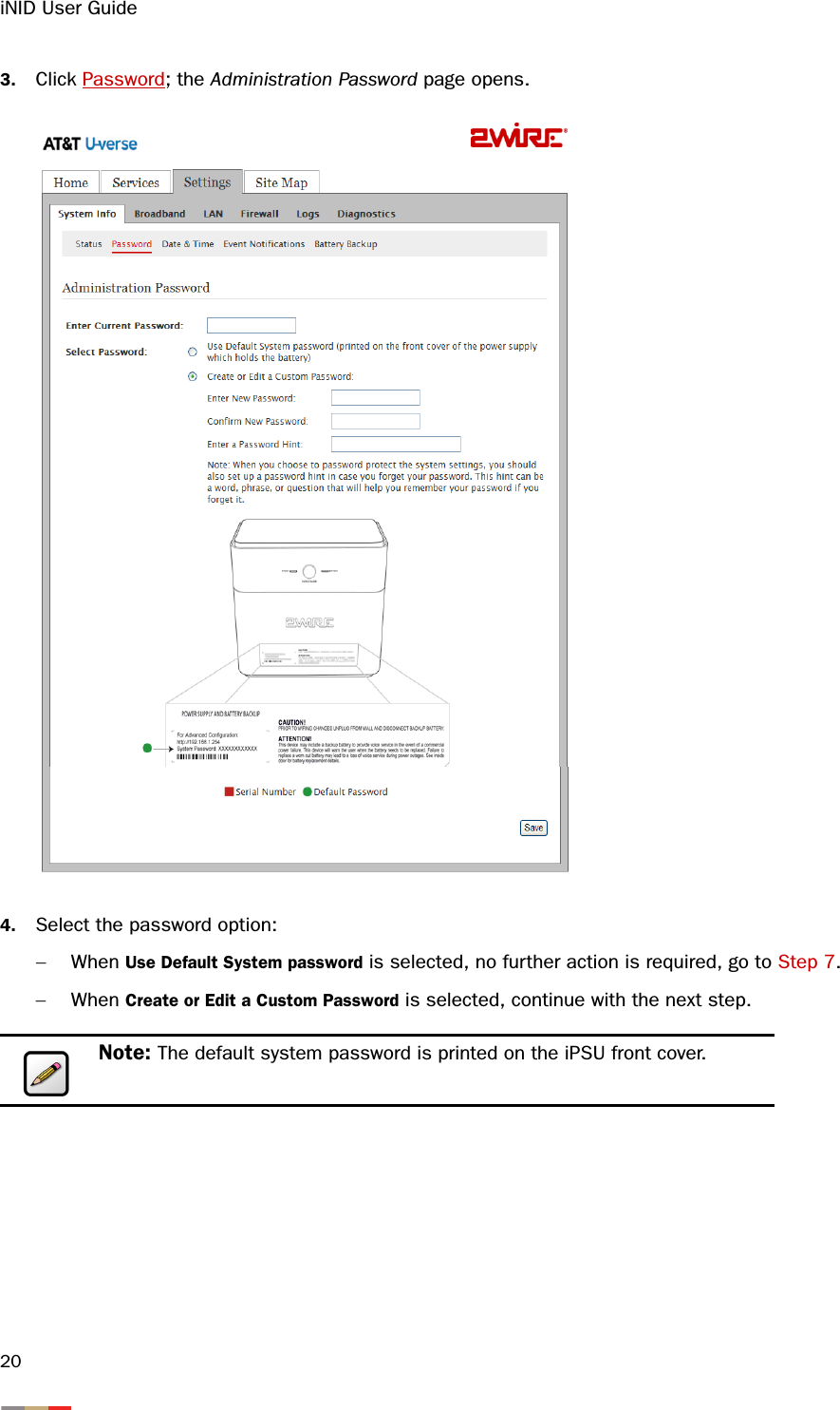
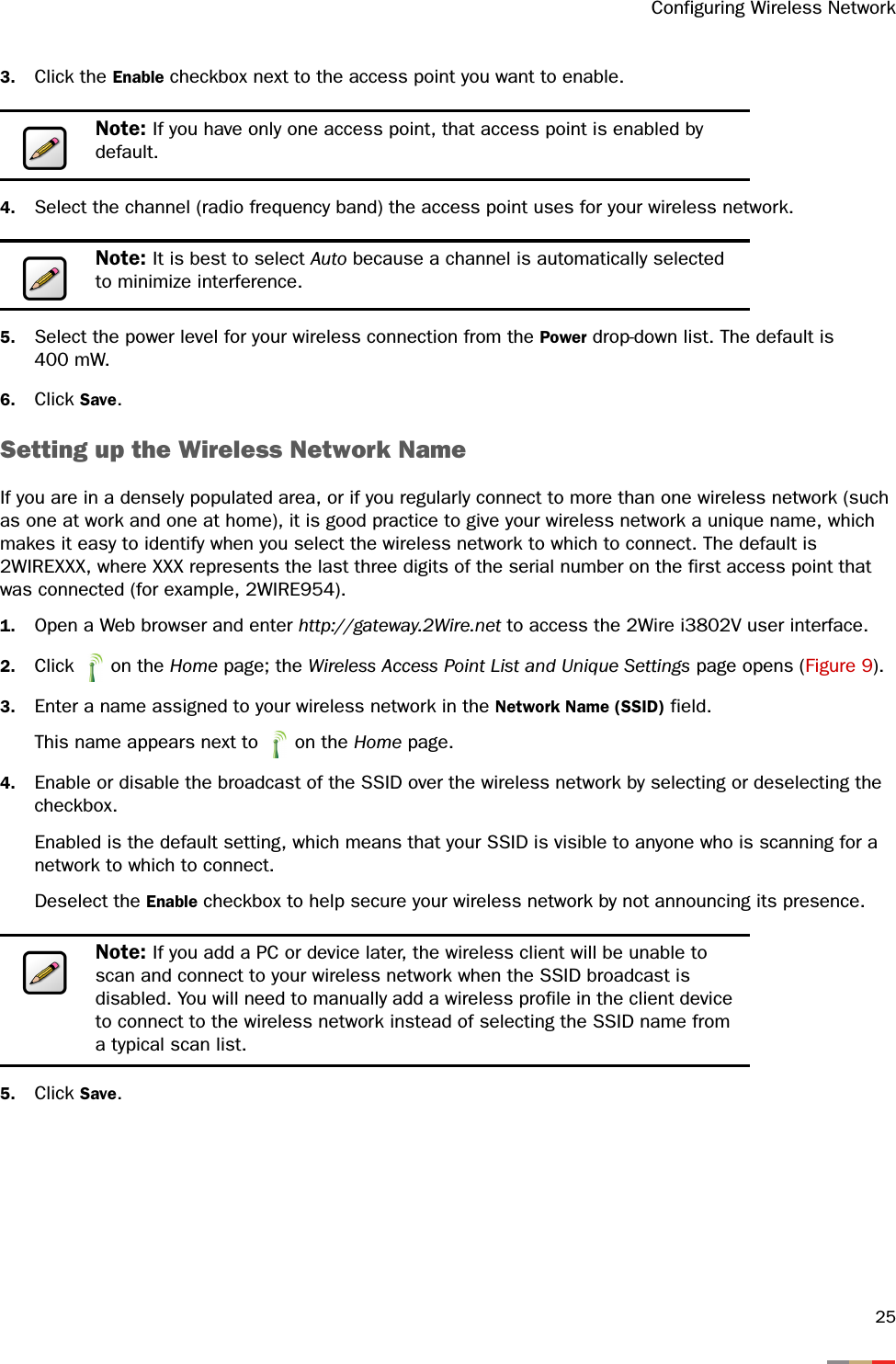
>
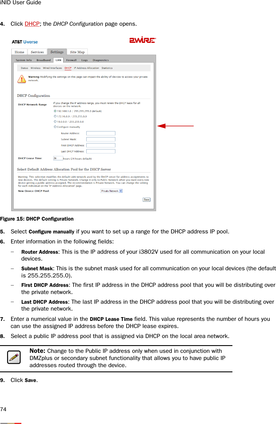
ARRIS
>
2WI38HG User Manual
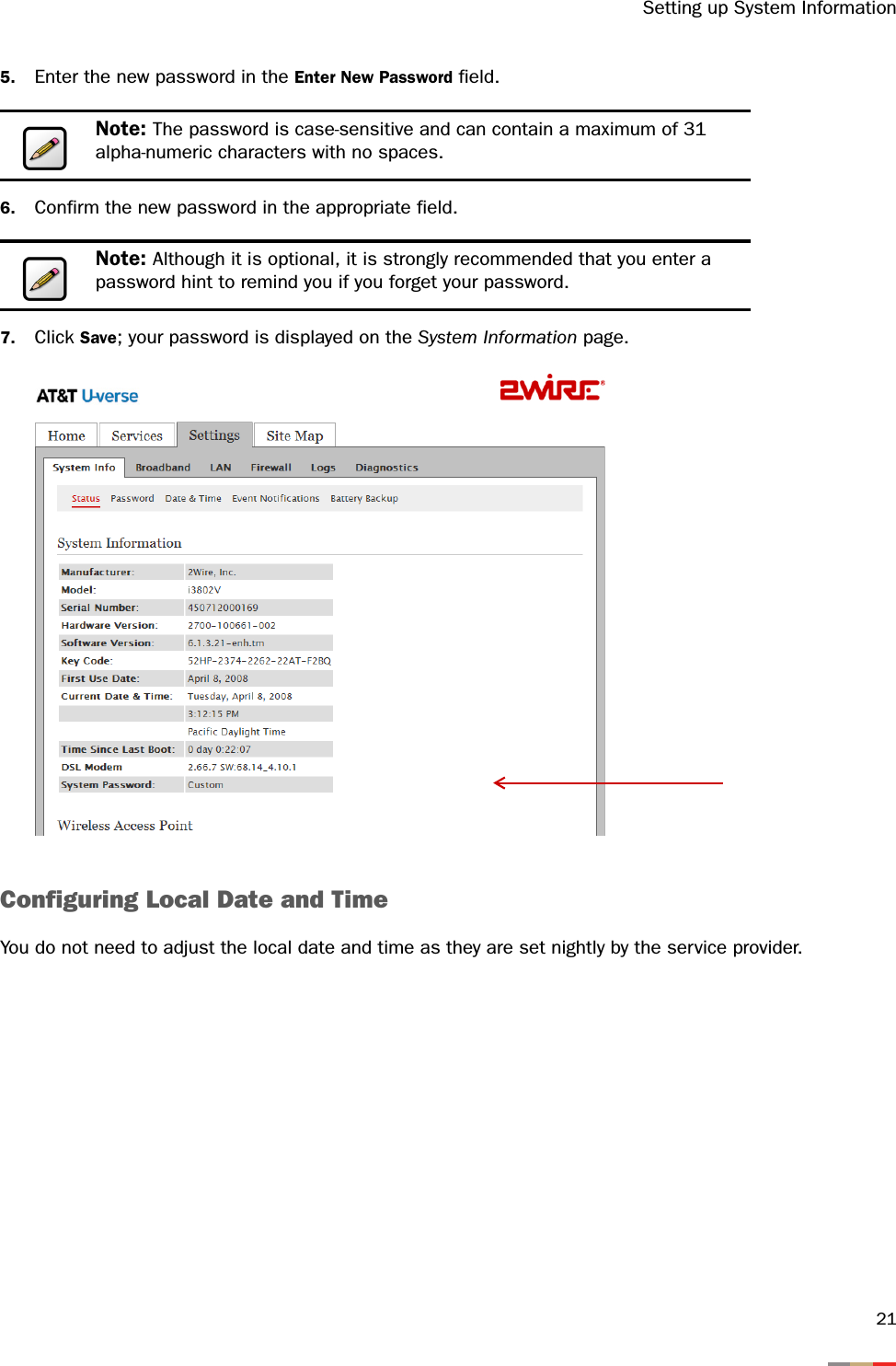
>
User manual
Contents
1.
User manual
2.
Users Manual
User manual
Navigation menu
Upload a User Manual
Namespaces
Wiki Guide
HTML
PDF
Info
Views
User Manual
Discussion / Help
Navigation
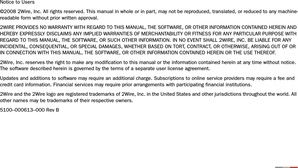

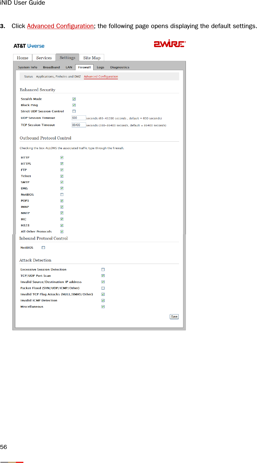
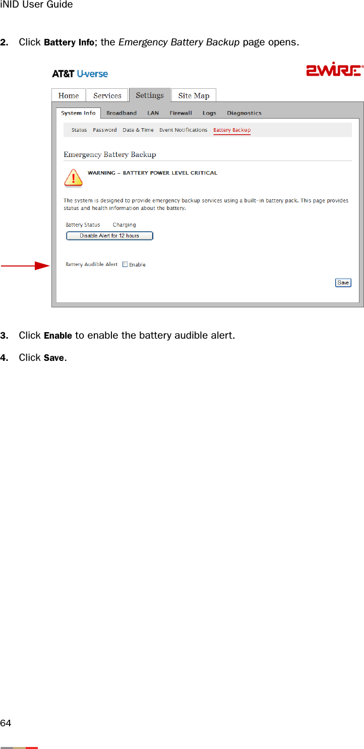
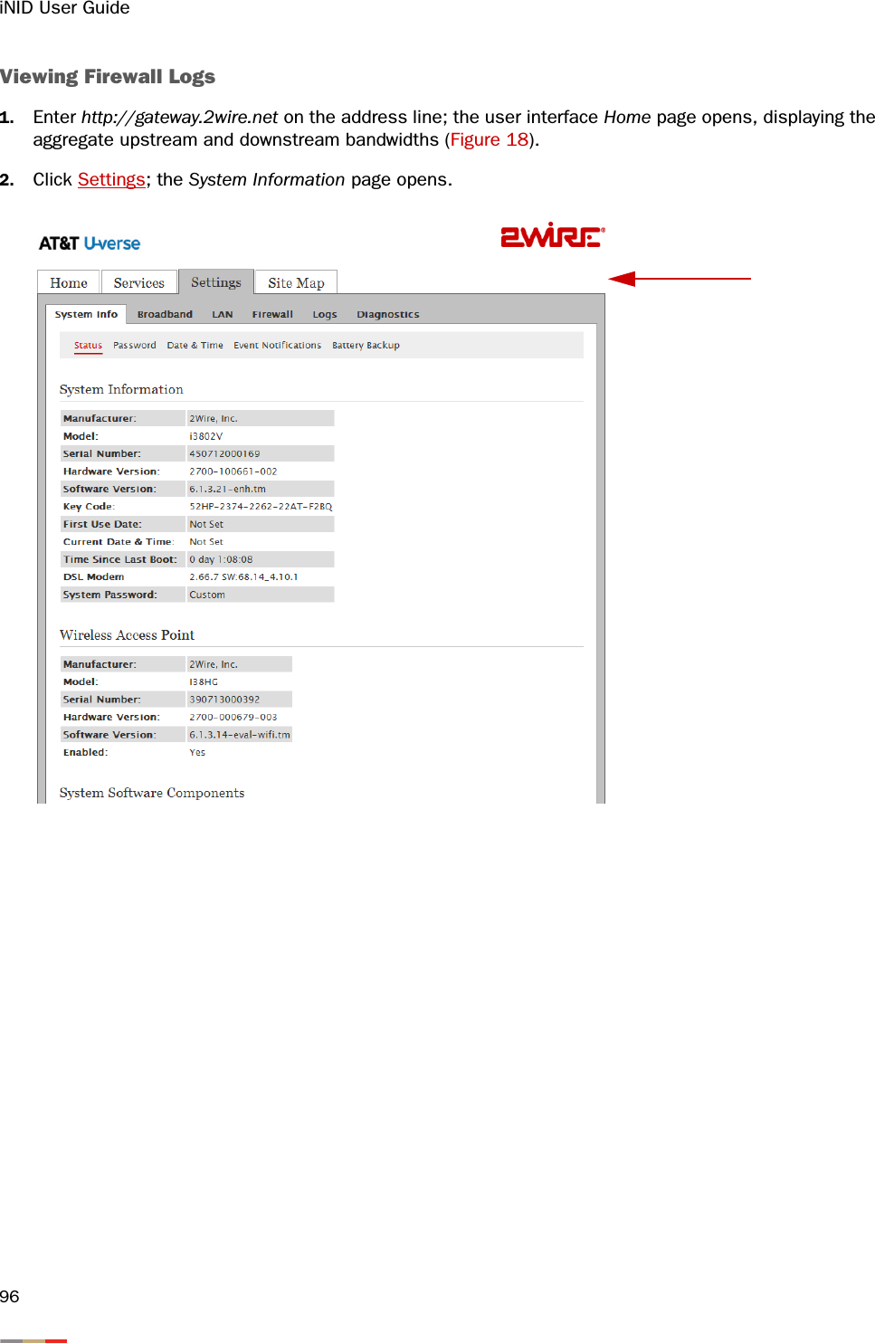
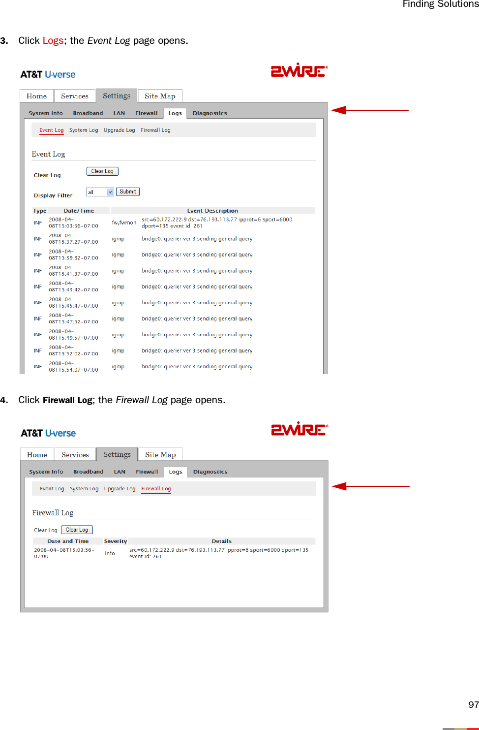
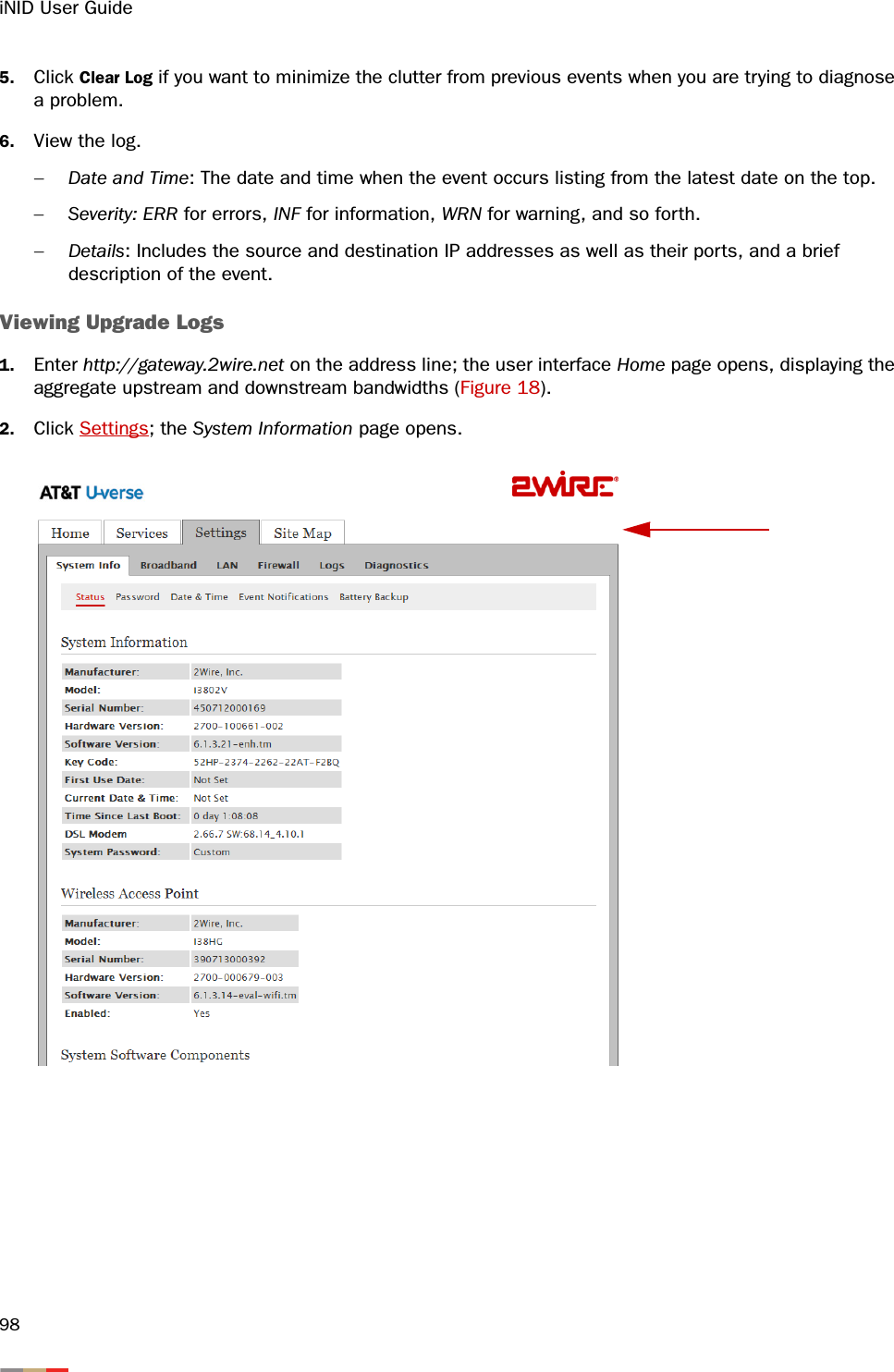
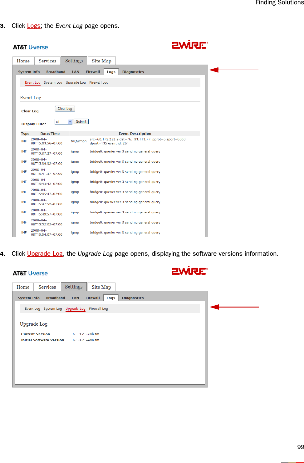
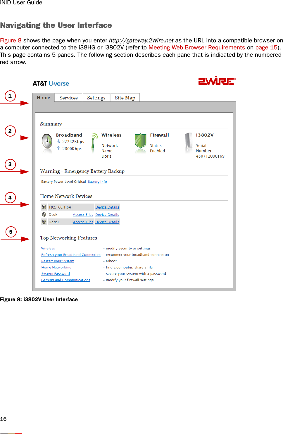
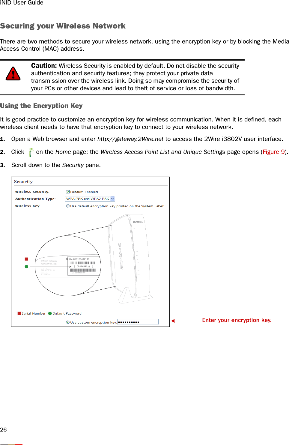
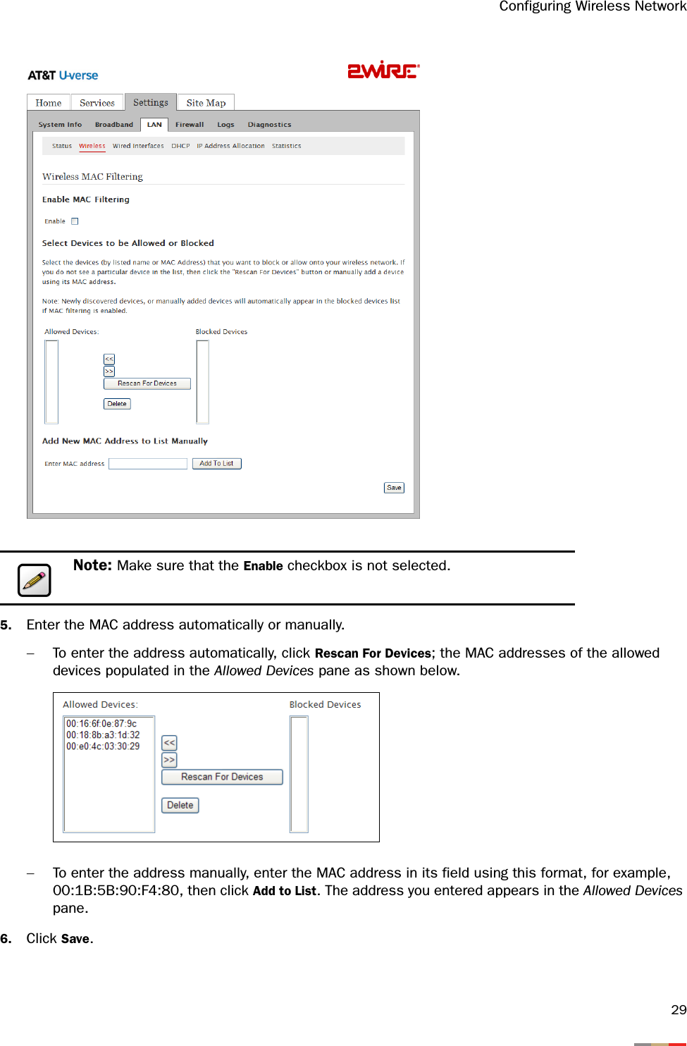
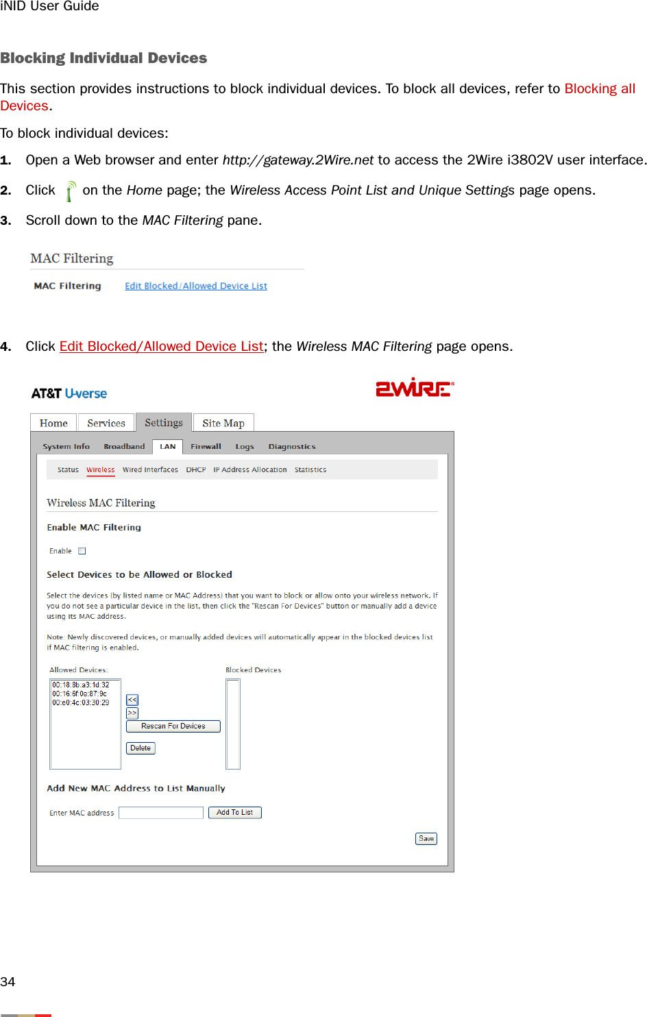
![iNID User Guide14Figure 7: Wireless Network Name and Encryption Key Location4. Enter the encryption key that is located inside the brackets beneath the bar code on the bottom of your i38HG, (for example, 4119627022). Note: For Mac OS X users, you may need to enter the “$” character at the beginning of the encryption key (for example, $4119627022). SN: 543811999110[ 4119627022 ]4200-000XXX-000i38HGMade in USAPatent PendingDC 5.1V 2A2Wire® Gatewaywww.2Wire.comComplies with 47 CFR Part 68US: 6KRDL01BiNIDIFCC ID PGR2Wi38HG Tested To Comply With FCC StandardsFLX239068SN: XXXXXXXXXXXX[ XXXXXXXXXX ]4200-000XXX-000](https://usermanual.wiki/ARRIS/2WI38HG.User-manual/User-Guide-977279-Page-18.png)
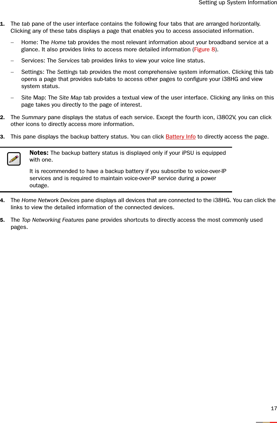

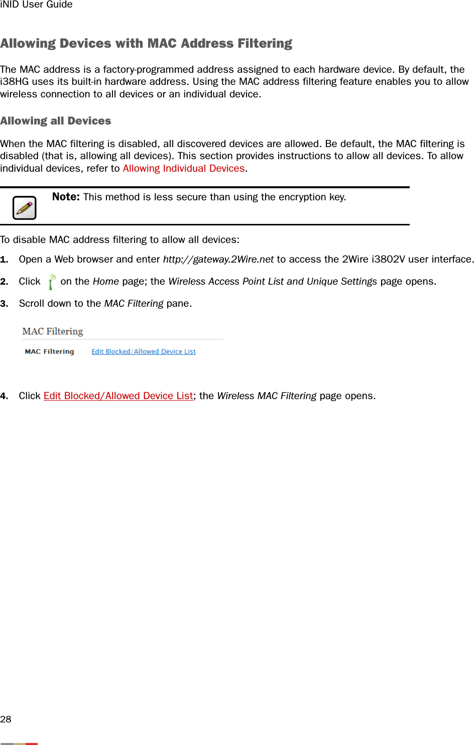
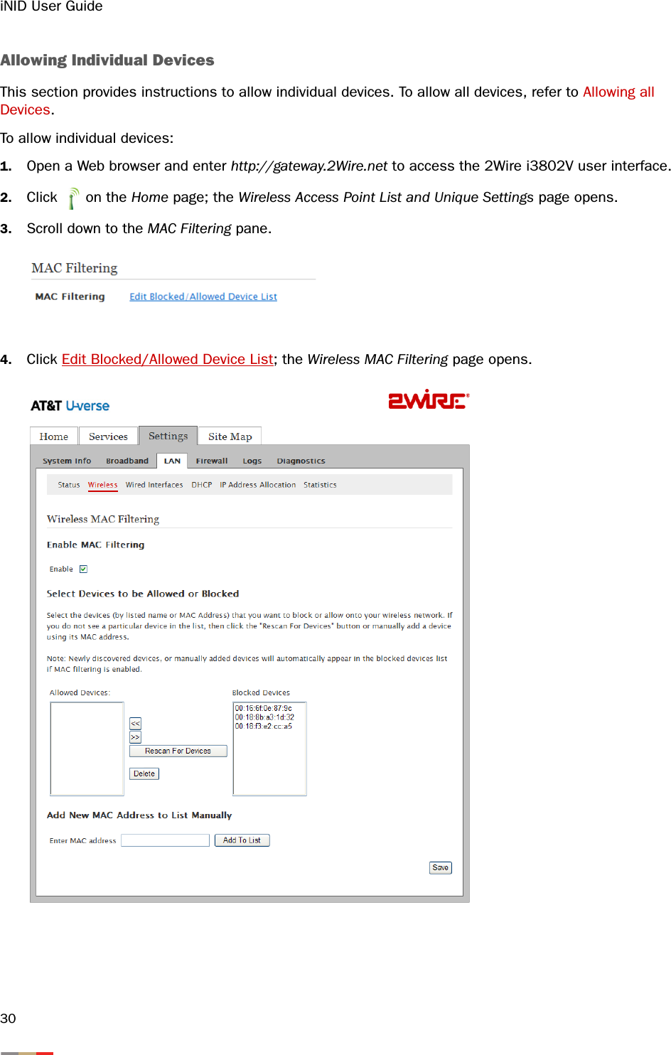
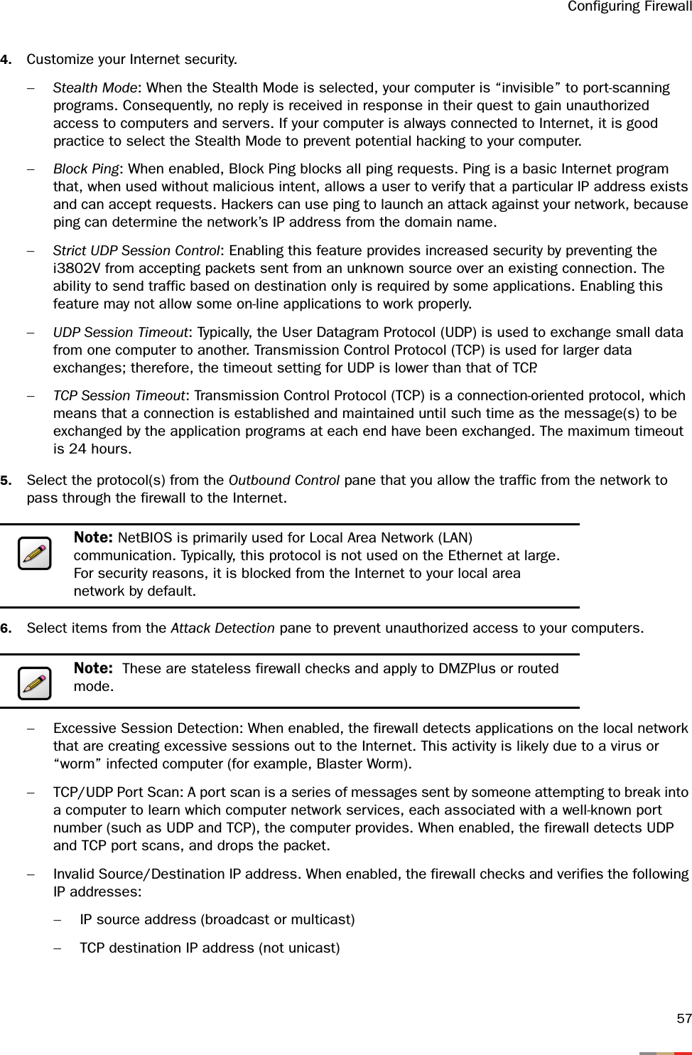
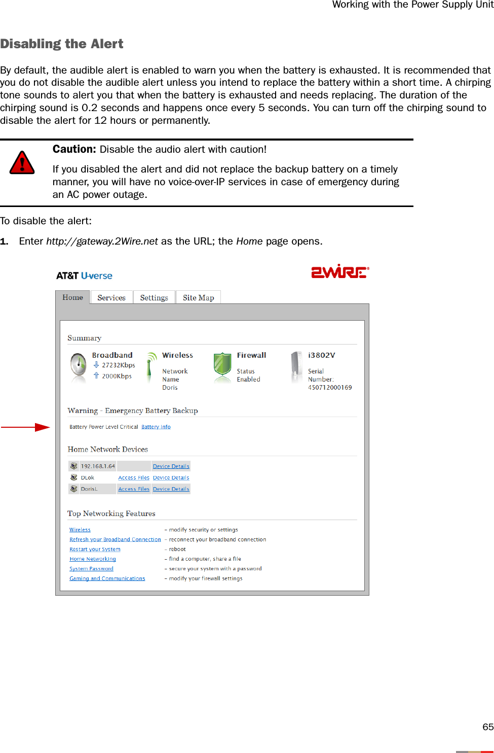
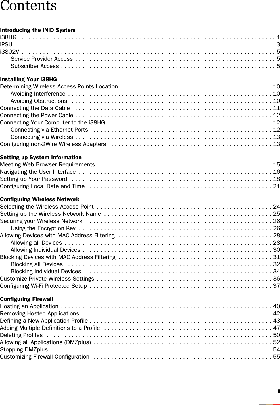
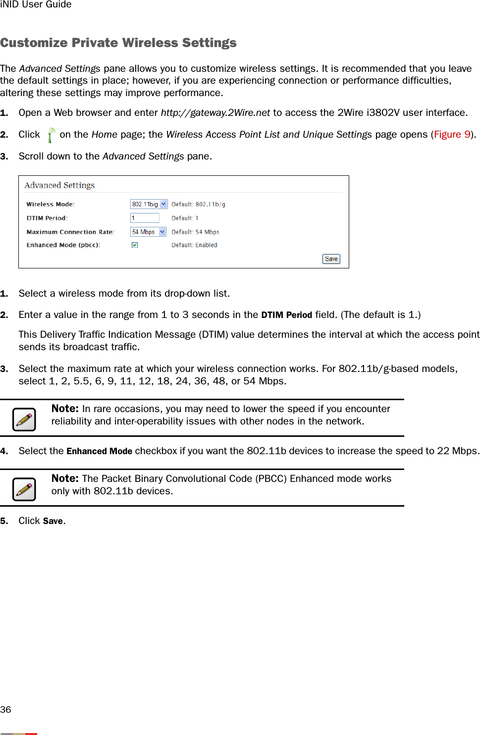
![Configuring Wireless Network315. Select the device you want to allow from the Blocked Devices pane.6. Click <<; the list(s) you selected appears in the Blocked Devices pane, as shown below.7. Click Save. Blocking Devices with MAC Address Filtering The MAC address is a factory-programmed address assigned to each hardware device. By default, the i38HG uses its built-in hardware address. When enabled, the wireless connection is blocked to the MAC address listed in the Allowed Devices pane. Using the MAC address filtering feature enables you to block wireless connection to all devices or an individual device. Note: Make sure that the Enable checkbox is selected; otherwise, the device will not be allowed. Note: To select multiple addresses, hold down the [Shift] or [Ctrl] keys while making your selections. Using the [Shift] key lets you make your selections in a contiguous order while the [Ctrl] key selects the groups in a random order.](https://usermanual.wiki/ARRIS/2WI38HG.User-manual/User-Guide-977279-Page-35.png)
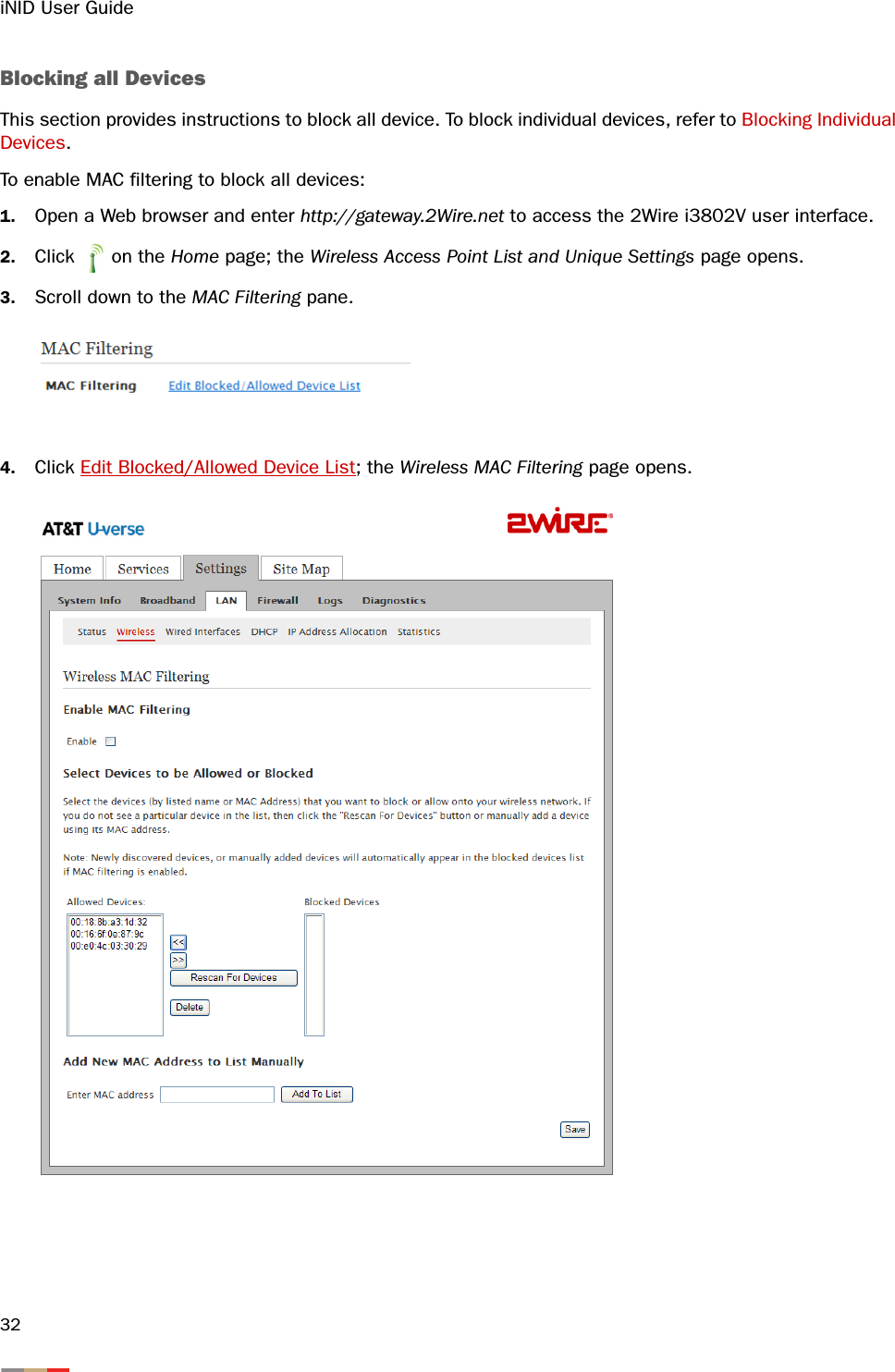
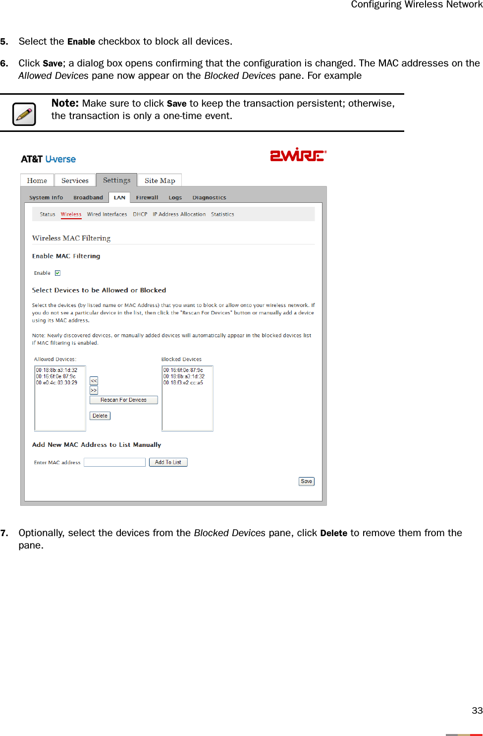
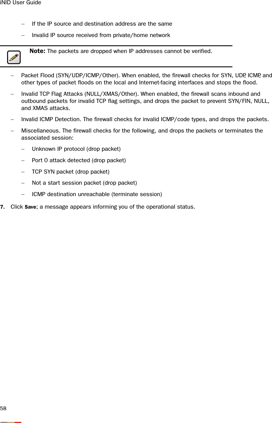
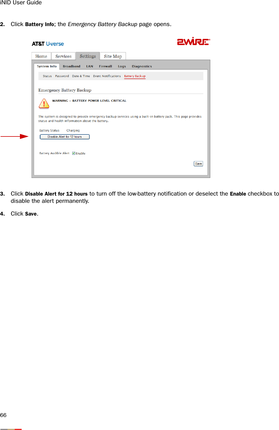
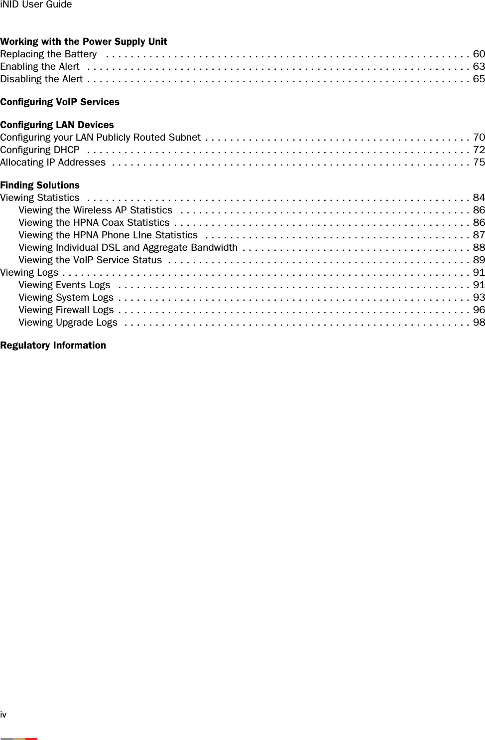
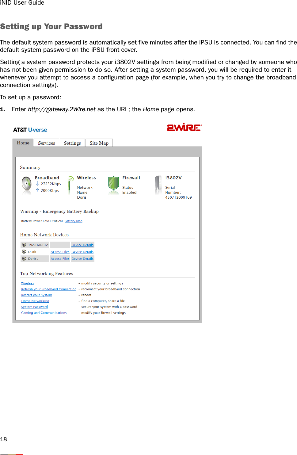
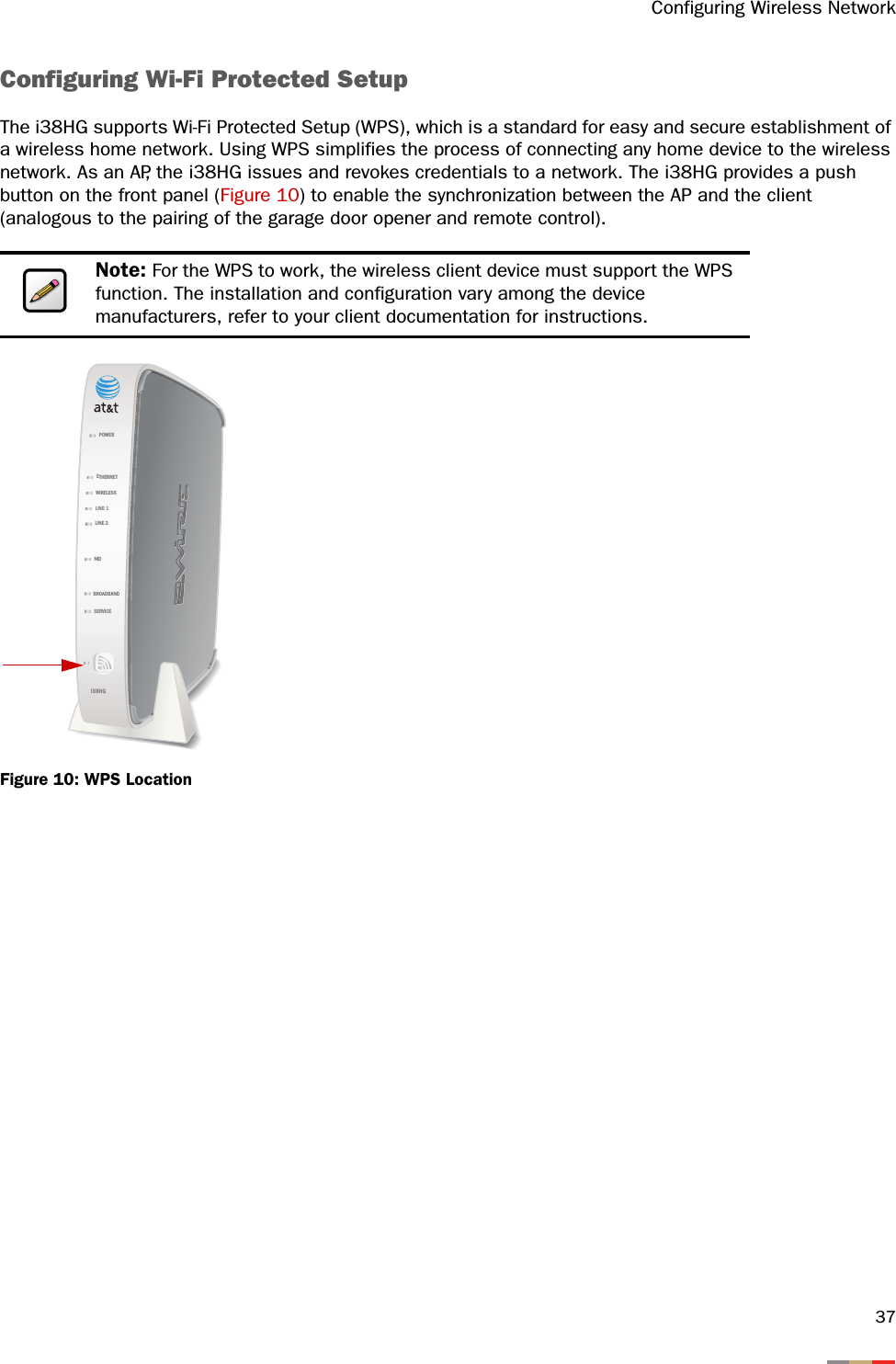
![Configuring Wireless Network355. Select the Enable checkbox to block all devices. 6. Click Save; a dialog box opens confirming that the configuration is changed. The MAC addresses on the Allowed Devices pane now appear on the Blocked Devices pane. 7. Select the device you want to block from the Allowed Devices pane.8. Click >>; the list(s) you selected appears in the Blocked Devices pane, as shown below.9. Click Save. Note: Make sure to click Save to keep the transaction persistent; otherwise, the transaction is only a one-time event. Note: To select multiple addresses, hold down the [Shift] or [Ctrl] keys while making your selections. Using the [Shift] key lets you make your selections in a contiguous order while the [Ctrl] key selects the groups in a random order.](https://usermanual.wiki/ARRIS/2WI38HG.User-manual/User-Guide-977279-Page-39.png)

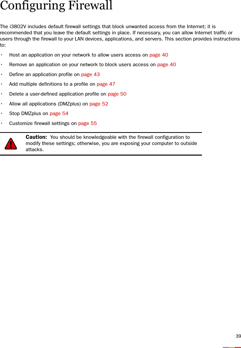
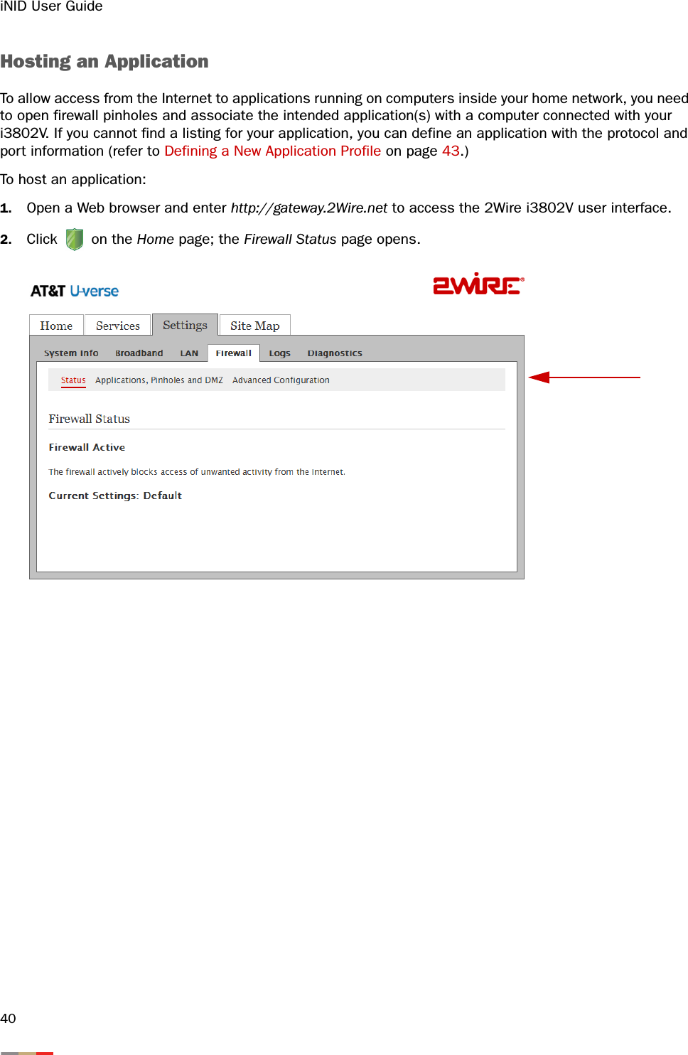
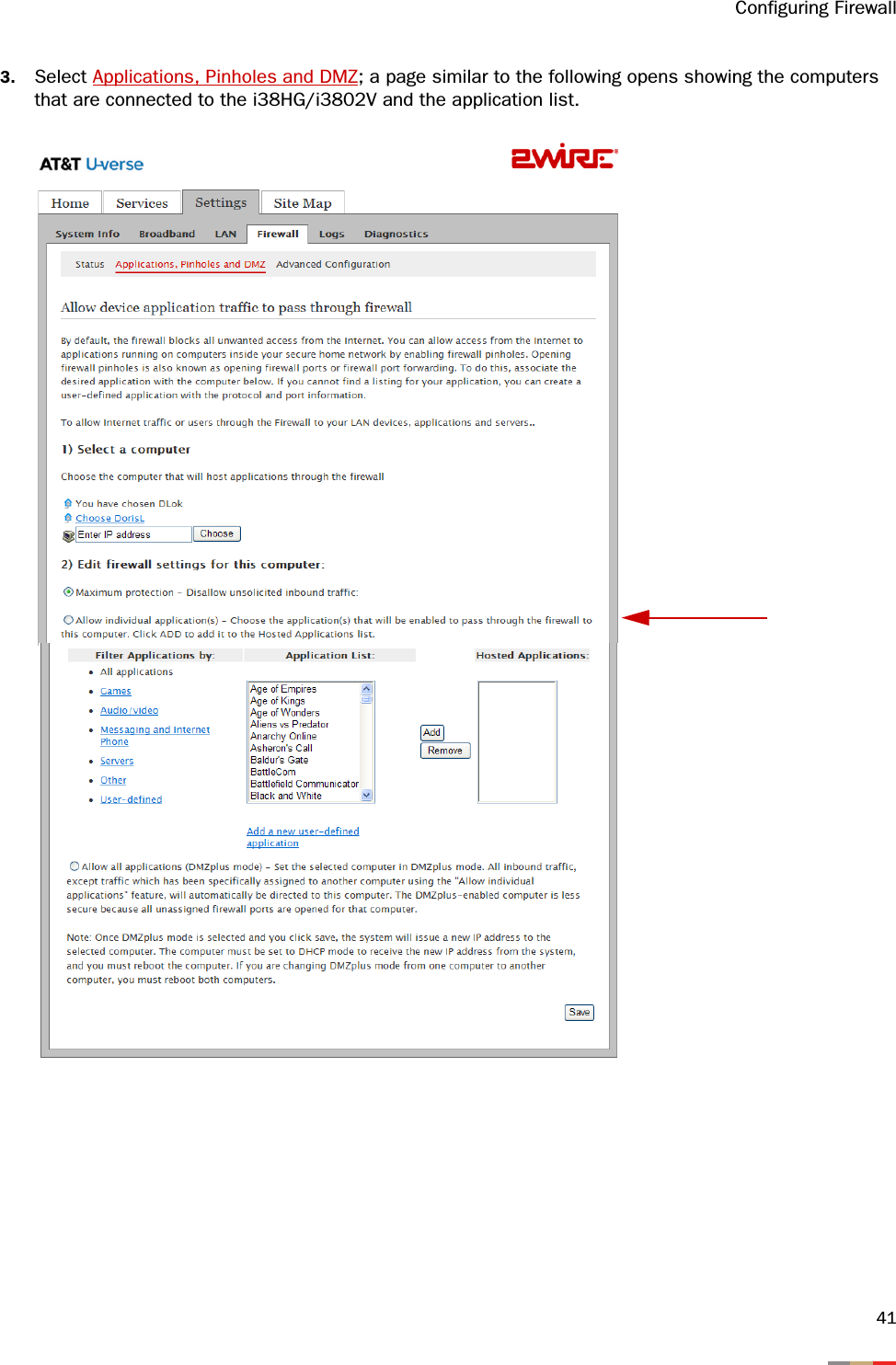
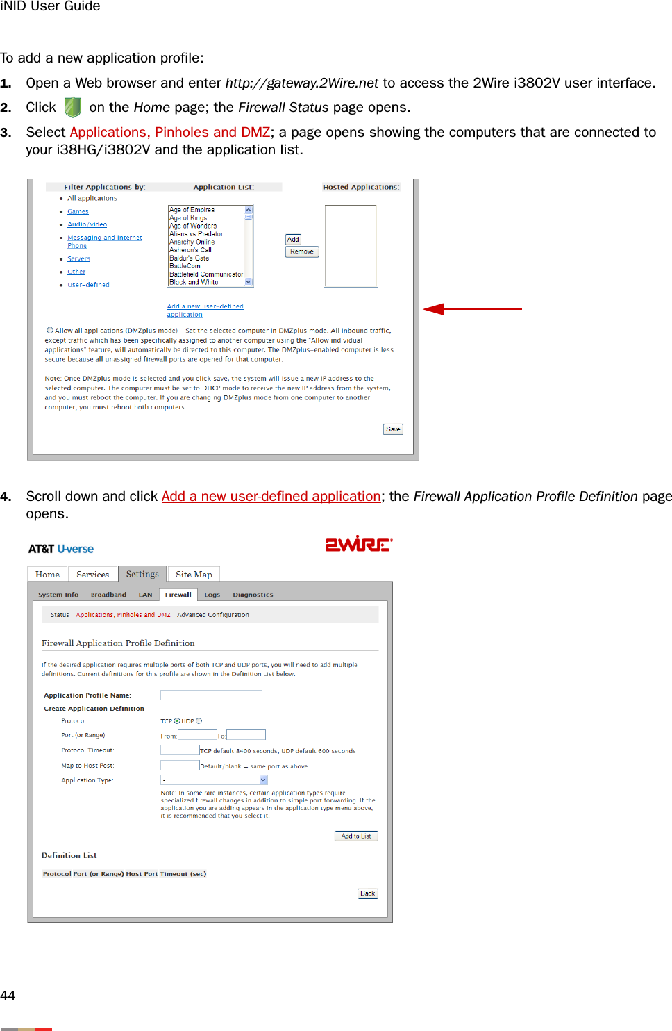
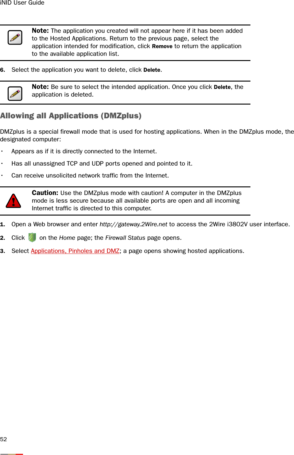
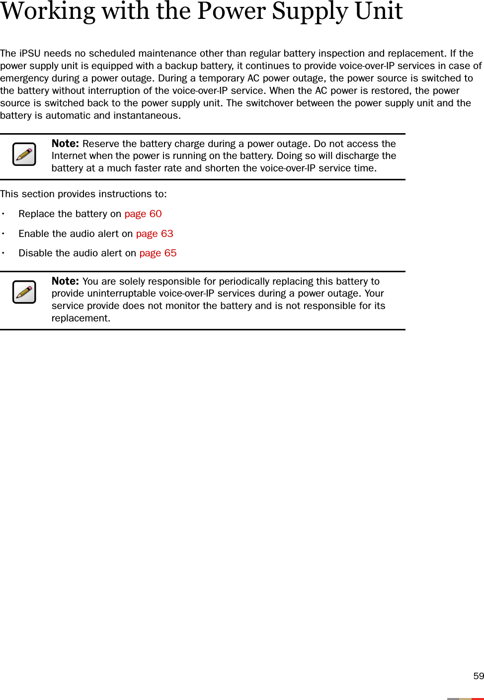
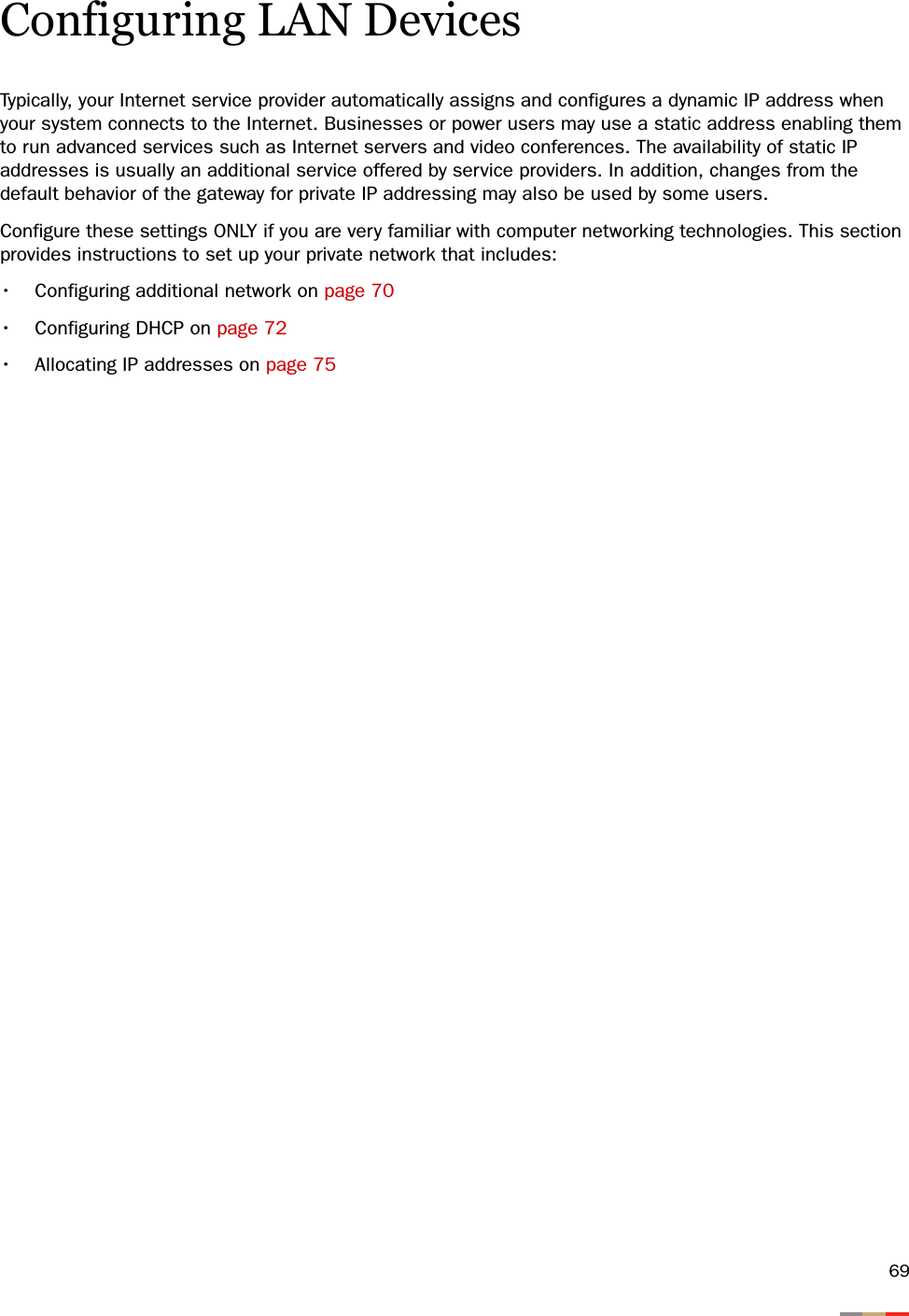
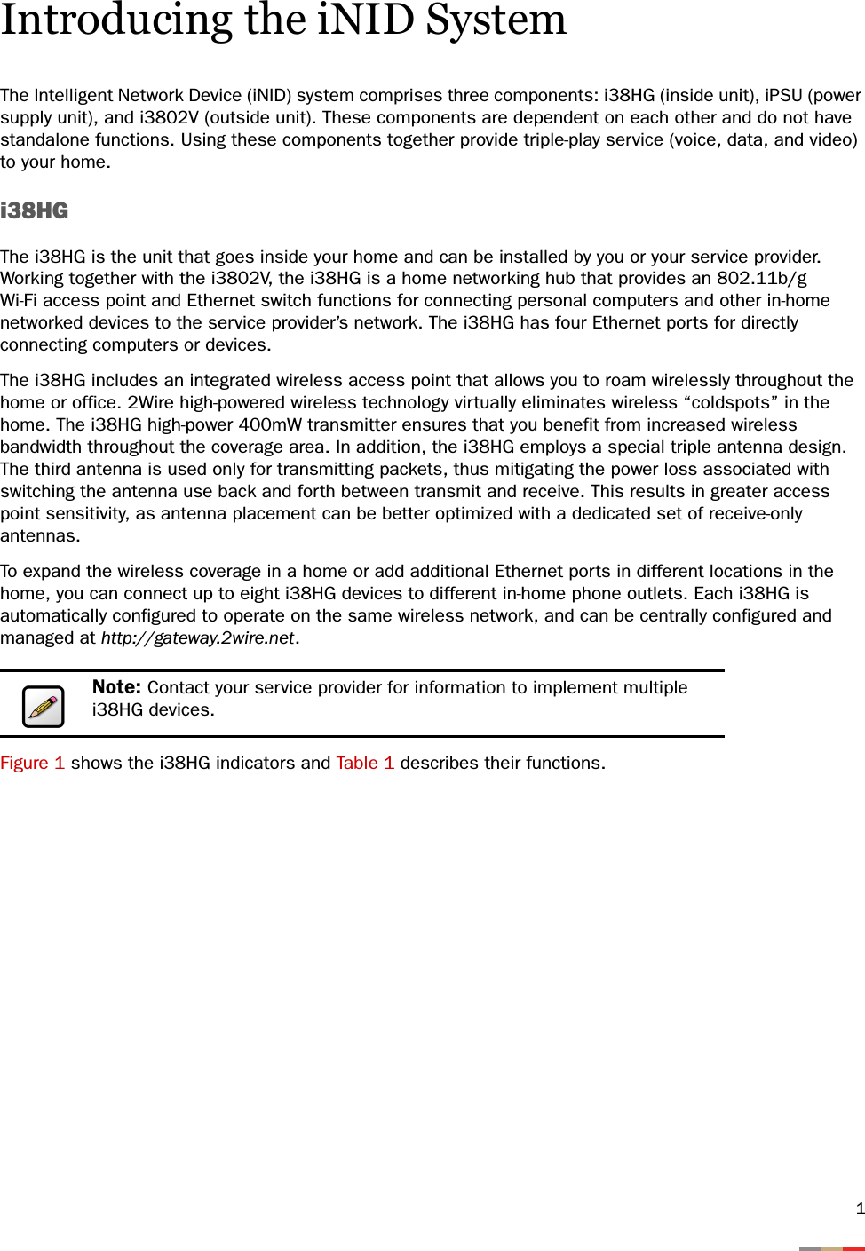
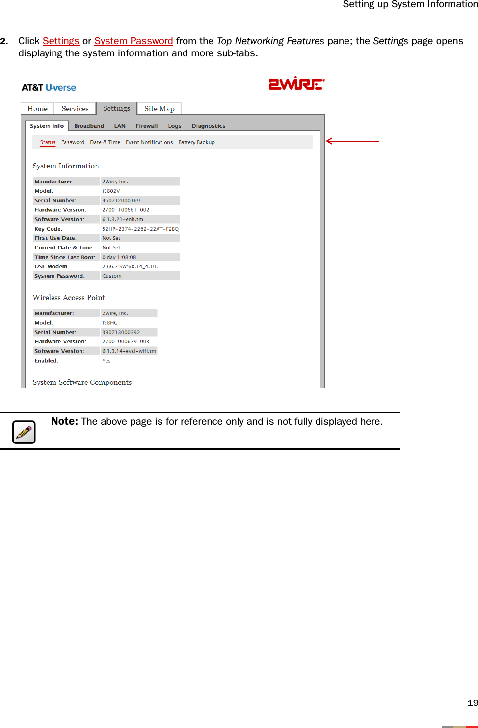
![iNID User Guide424. Select the computer that you want to host the application(s). 5. Select Allow individual application(s). 6. Filter the application list by selecting the category; your selection is displayed in the Application List panel. 7. Select from the Application List panel the application(s) you want to host. 8. Click Add; the application(s) you selected appears in the Hosted Applications panel. 9. Click Save; a message appears informing you the status. Removing Hosted Applications1. Open a Web browser and enter http://gateway.2Wire.net to access the 2Wire i3802V user interface. 2. Click on the Home page; the Firewall Status page opens, displaying the current hosted application settings. Note: If the computer you want to select is unlisted because it is powered off and the “hide inactive devices” option is enabled; you still can select it as long as it is on the same network and you know its IP address. Replace “Enter IP address” with the intended IP address, then click Choose. Note: To select multiple applications, hold down the [Shift] or [Ctrl] keys while making your selections. Using the [Shift] key lets you make your selections in a contiguous order while the [Ctrl] key selects the groups in a random order.](https://usermanual.wiki/ARRIS/2WI38HG.User-manual/User-Guide-977279-Page-46.png)
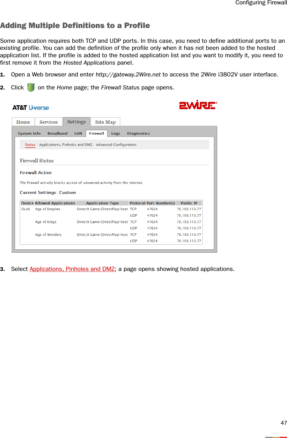
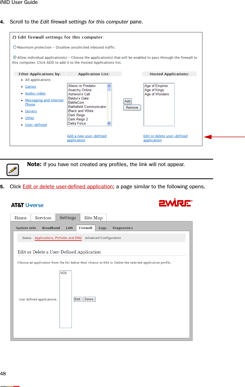
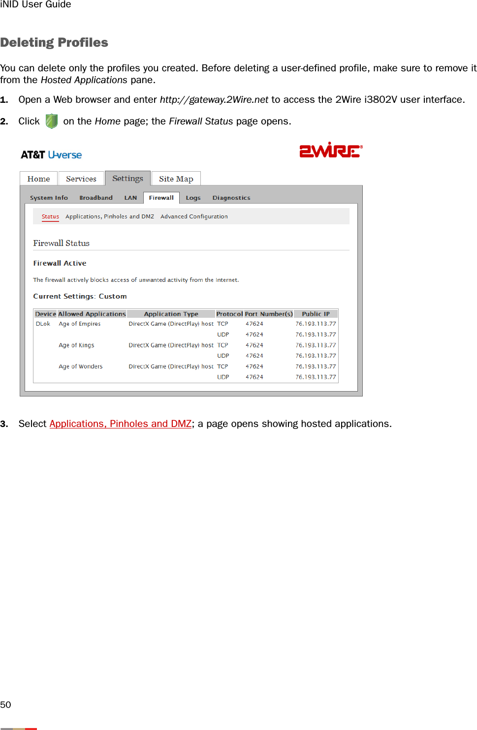
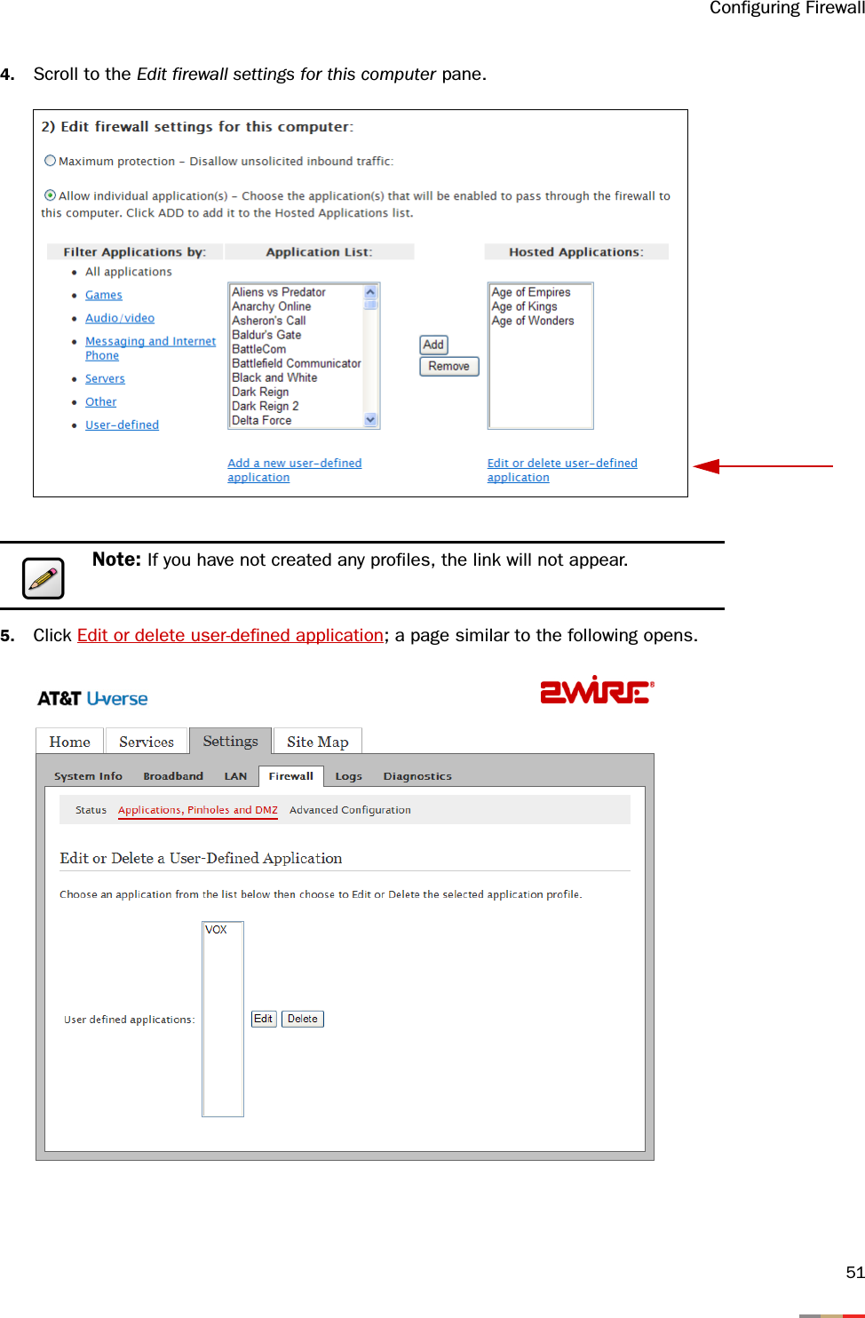
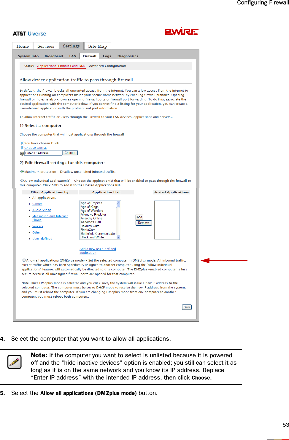
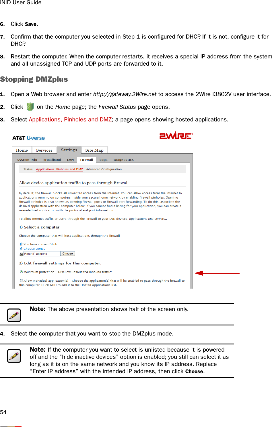
![Configuring Firewall433. Select Applications, Pinholes and DMZ; a page opens showing hosted applications. 4. Select the hosting computer if you do not see the pinhole you want to remove in the list. 5. Scroll to the Edit firewall settings for this computer pane. 6. Select the application(s) you want to remove from the Hosted Applications panel, click Remove.7. Click Save; a message appears informing you the status. The application(s) you selected is removed from the Hosted Applications panel and returned to the Application List panel. Defining a New Application ProfileAn application profile configures your system’s firewall to pass through application-specific data. You can define an application profile that is not included in the Application List. This feature is typically used if the application for which you would like to pass through data to a given computer is new or has been recently updated to a new version.Note: To select multiple applications, hold down the [Shift] or [Ctrl] keys while making your selections. Using the [Shift] key lets you make your selections in a contiguous order while the [Ctrl] key selects the groups in a random order.](https://usermanual.wiki/ARRIS/2WI38HG.User-manual/User-Guide-977279-Page-47.png)