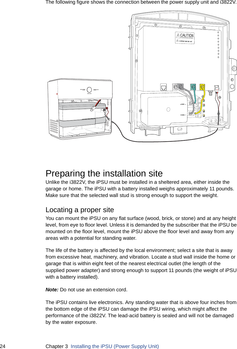
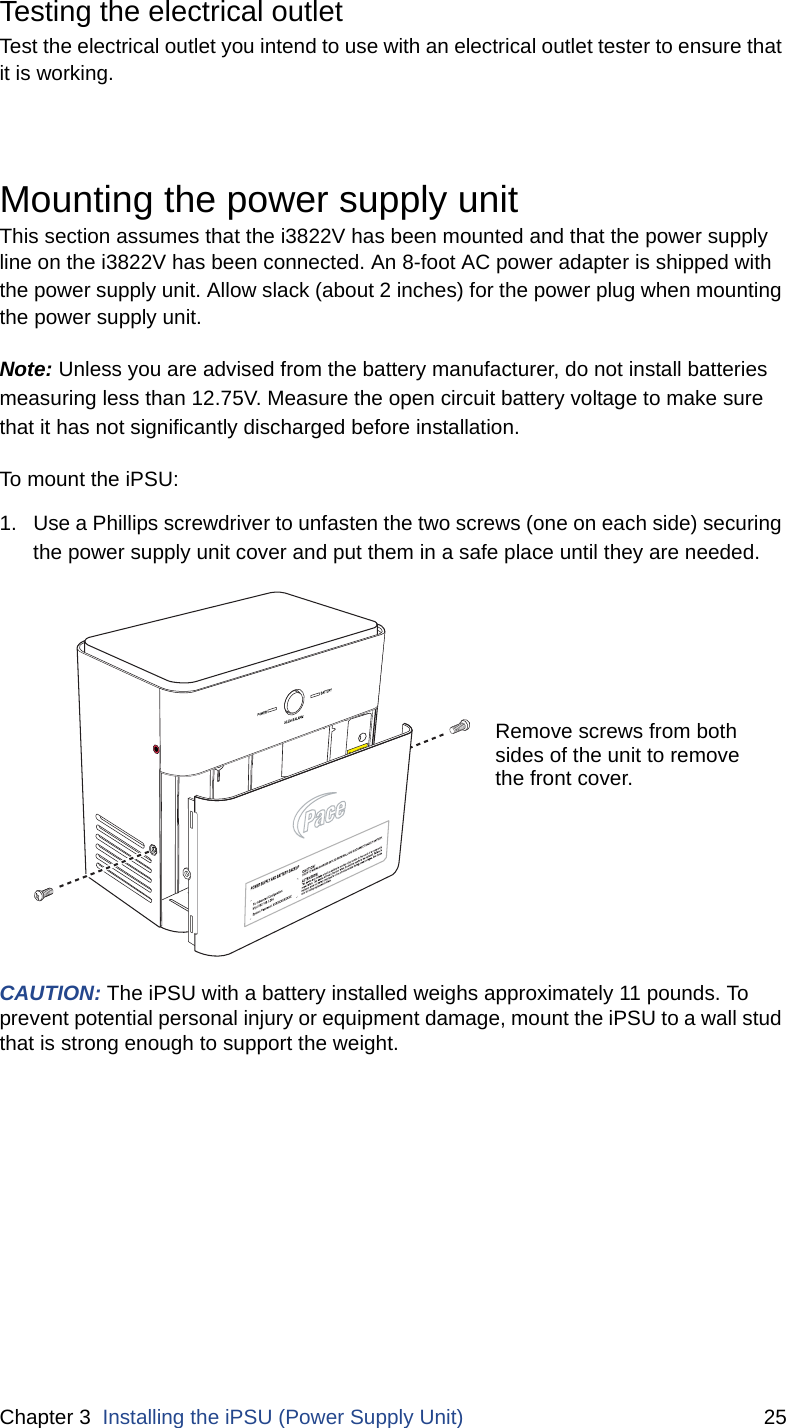
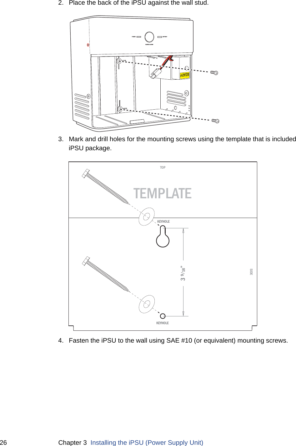
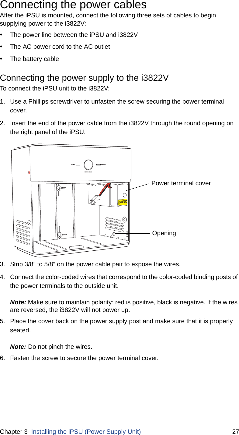
ARRIS 2WI38HG Wireless 802.11g VDSL Residential Gateway User Manual iNID Installation Guide
Pace Americas Wireless 802.11g VDSL Residential Gateway iNID Installation Guide
ARRIS >
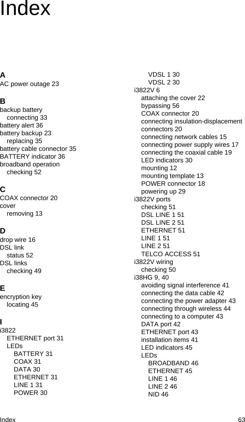
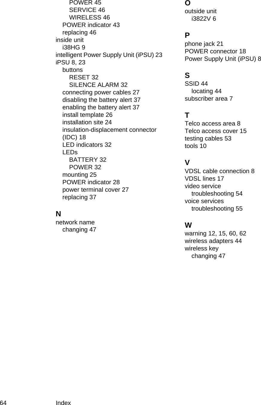
Contents
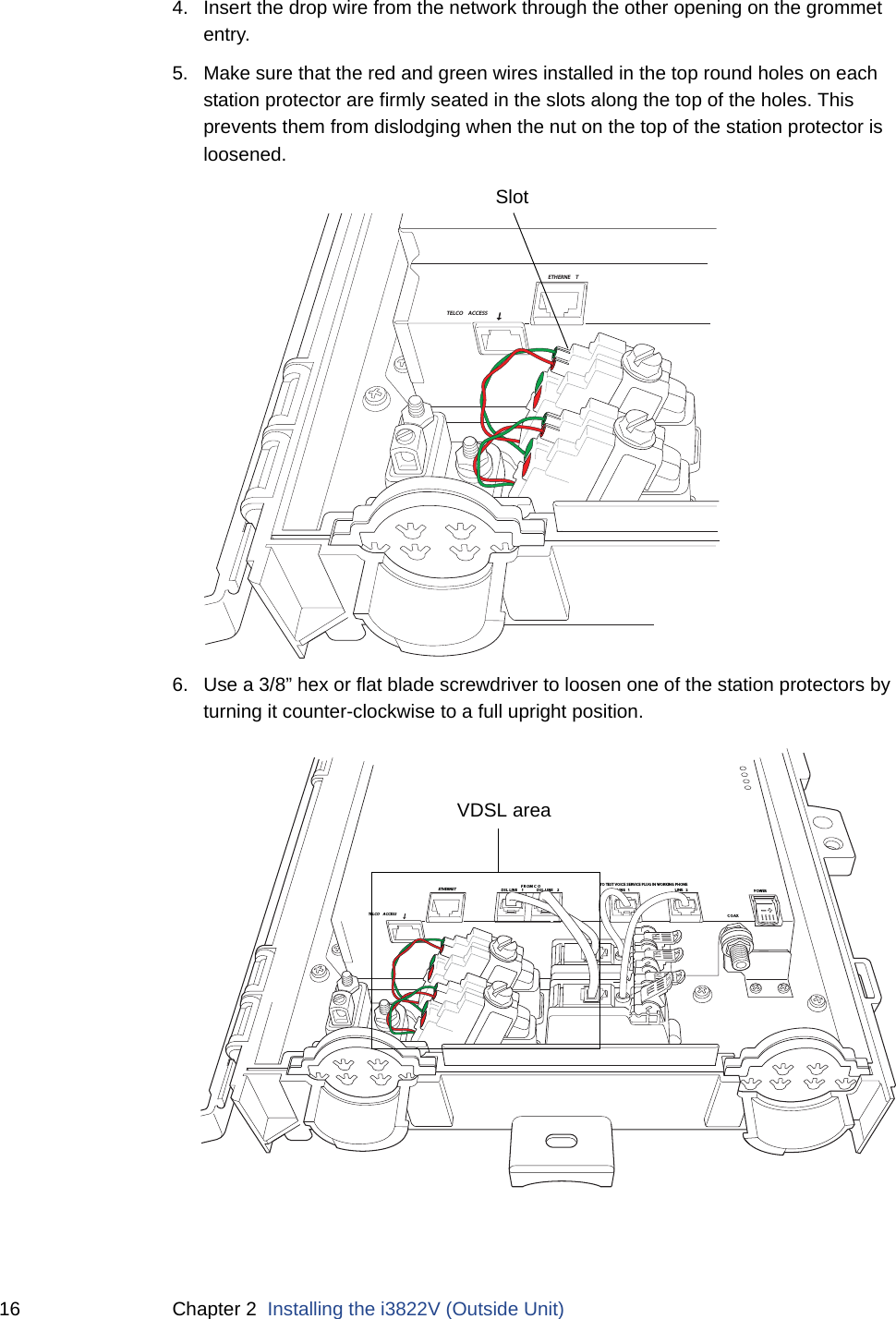
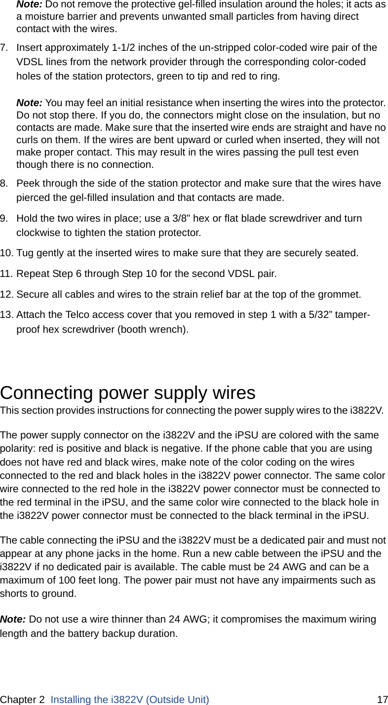
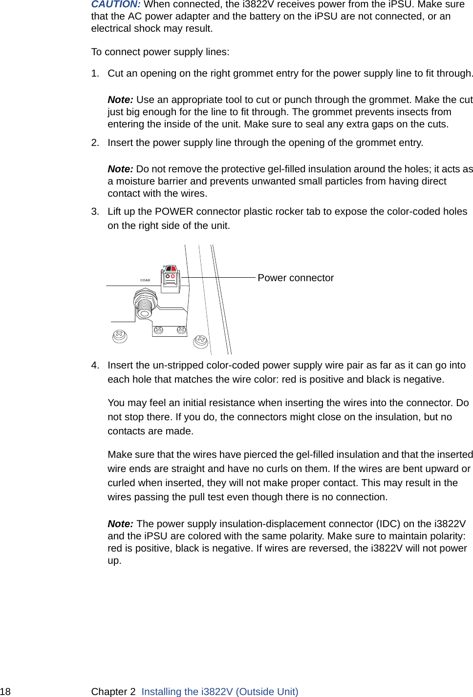
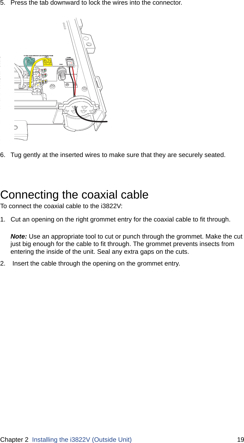
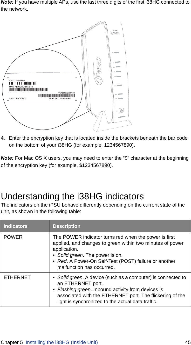
- 1. User manual
- 2. Users Manual
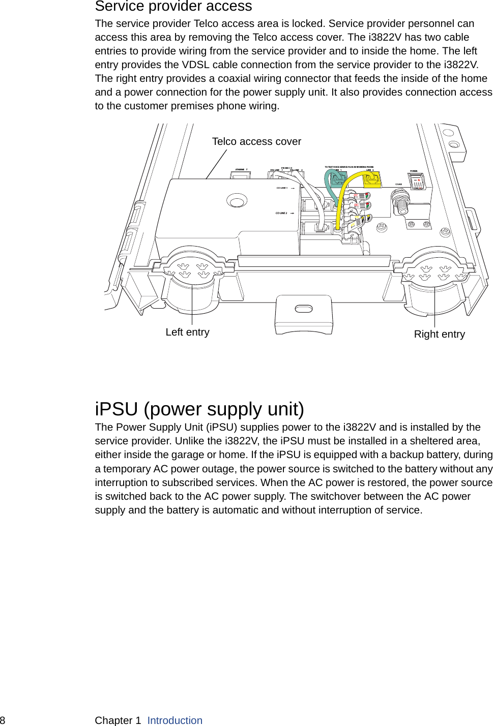
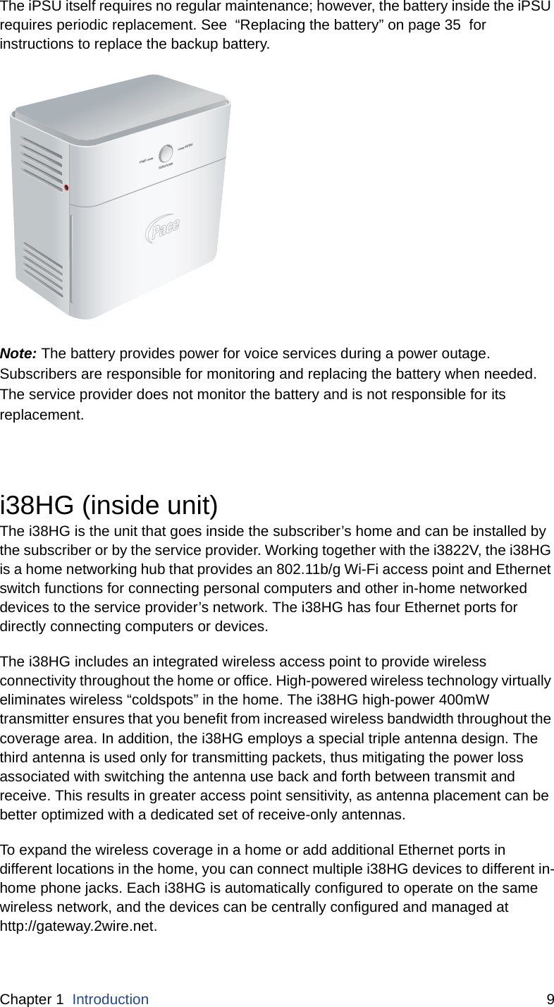
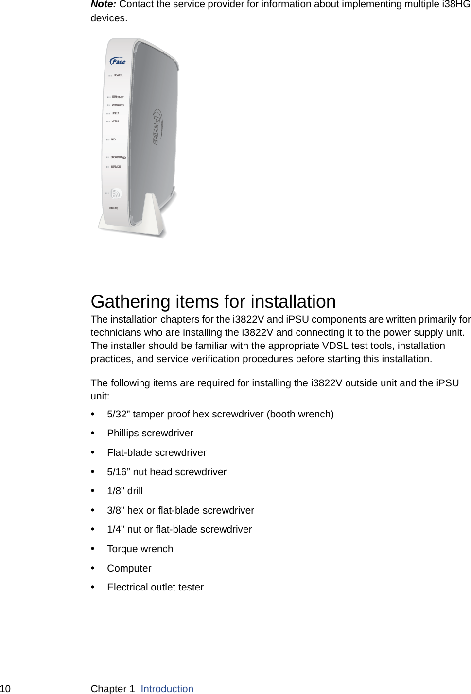
Users Manual

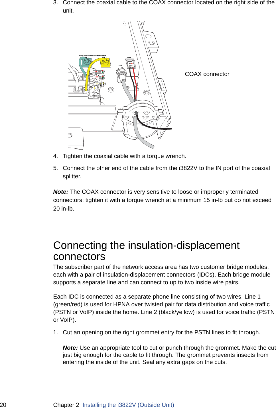
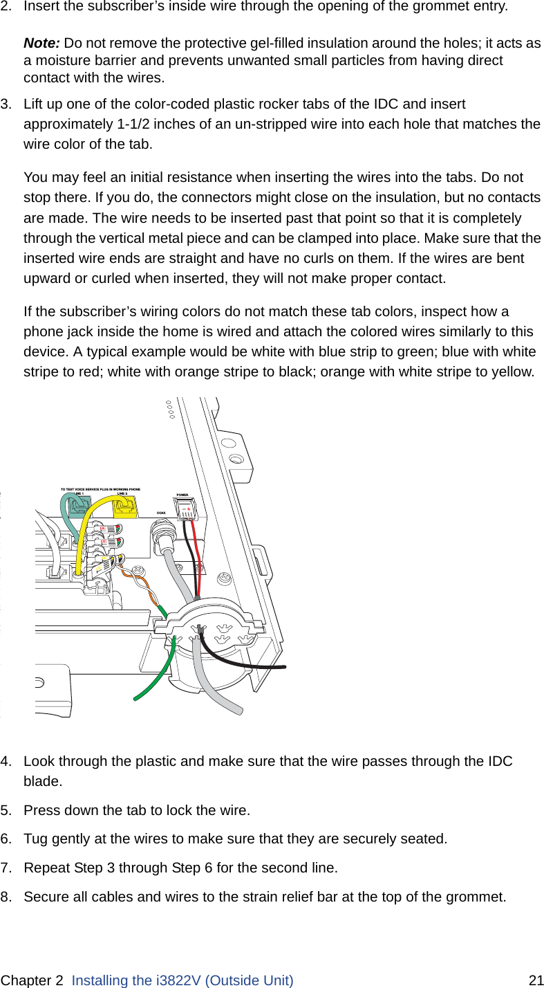
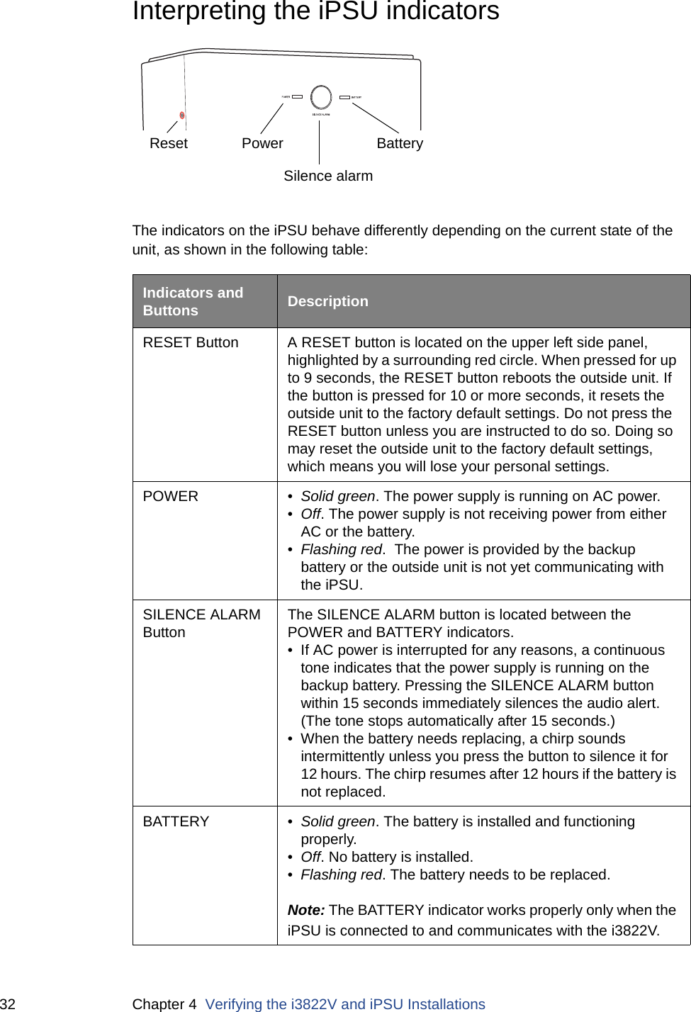
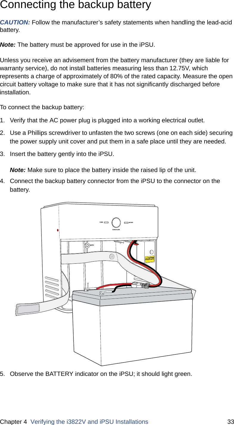
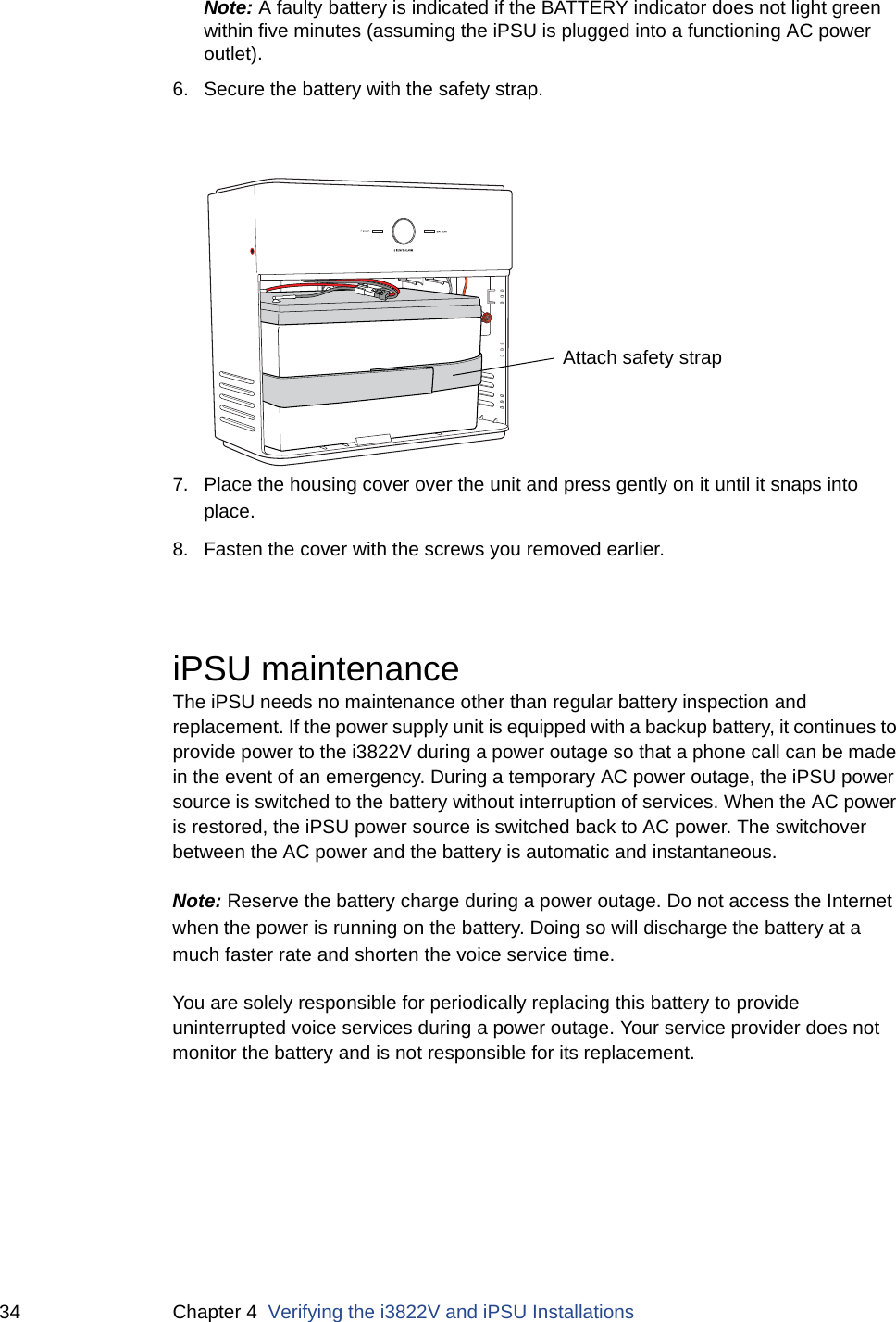
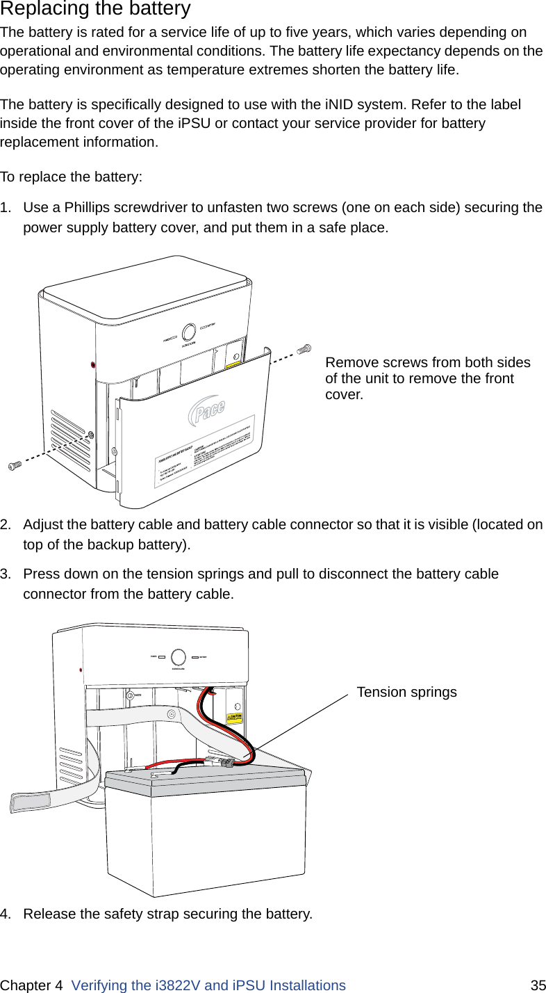
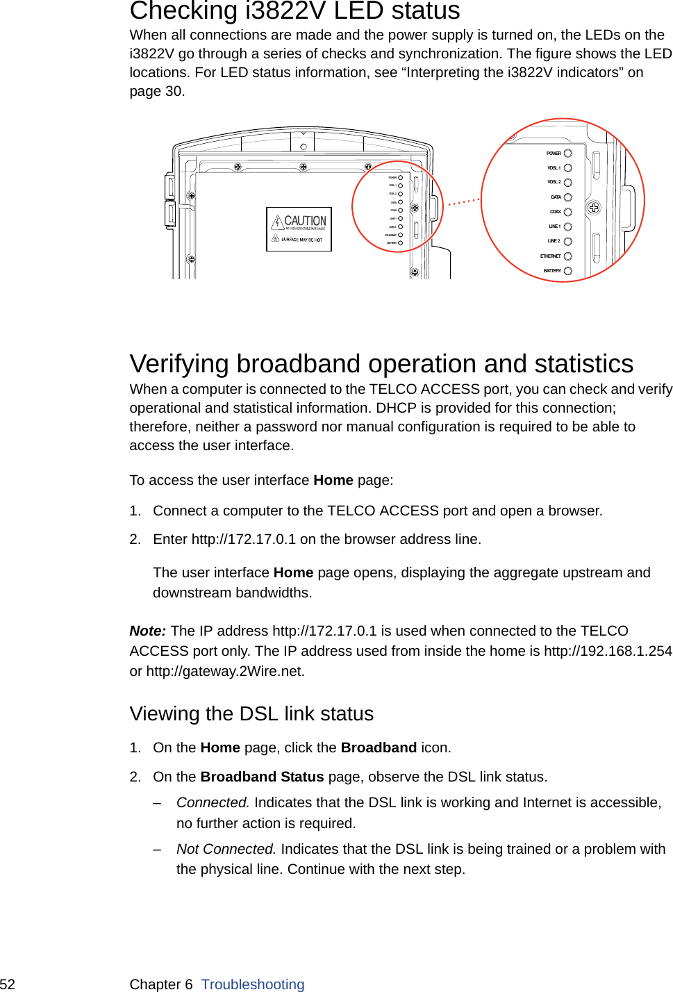
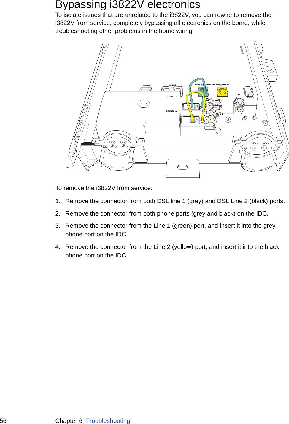
![58 Appendix A Regulatory Informationexcessive voltage fluctuations or emit electrical noise (for example, air conditioners, neon signs, high-frequency or magnetic security devices, or electric motors).EquipmentRepairsDo not, under any circumstances, attempt any service, adjustments, or repairs on this equipment. Instead, contact your local Pace distributor or service provider for assistance. Failure to comply may void the product warranty.Location – environmental considerationsDo not plug the AC/DC power adapter into an outdoor outlet or operate the residential gateway outdoors. It is not waterproof or dustproof, and is for indoor use only. Any damage to the unit from exposure to rain or dust may void your warranty. Do not use the residential gateway where there is high heat, dust, humidity, moisture, or caustic chemicals or oils. Keep the gateway away from direct sunlight and anything that radiates heat, such as a stove or a motor.Do not place the gateway in enclosed areas having restricted airflow, such as, electrical cabinet, closet, or entertainment center. Allow adequate ventilation around the gateway for maximum air flow and cooling. Declaration of conformityTrade Name. Pace AmericasResponsible Party. 2Wire, Inc. DBA Pace AmericaAddress. 1704 Automation Parkway, San Jose, CA 95131Phone. (408) 428-9500FCC / Industry Canada complianceThis device has been tested and certified as compliant with the regulations and guidelines set forth in the Federal Communication commission - FCC part 15, FCC part 68 and Industry Canada - ICES003 and RSS-210 Radio and telecommunication regulatory requirements.Le présent materiel est conforme aux specifications techniques applicables d'Industrie Canada. Cet appareil numérique de la classe [*] est conforme à la norme NMB-003 du Canada.Manufacturer: 2Wire, Inc. DBA Pace AmericasModels: i3822V, iPSU, iPSU2, i38HG, 4181N](https://usermanual.wiki/ARRIS/2WI38HG.Users-Manual/User-Guide-1516418-Page-58.png)