ARRIS 2WI38HG Wireless 802.11g VDSL Residential Gateway User Manual iNID Installation Guide
Pace Americas Wireless 802.11g VDSL Residential Gateway iNID Installation Guide
ARRIS >
Contents
- 1. User manual
- 2. Users Manual
Users Manual

INSTALLATION GUIDE
HomePortal Intelligent Gateway
i3822V
i38HG
iPSU
© 2011 Pace plc. All rights reserved.
Pace and the Pace logo are registered trademarks of Pace plc. All other trademarks are the property of their respective owners.
Pace provides no warranty with regard to this manual, the software, or other information contained herein, and hereby expressly
disclaims any implied warranties of merchantability or fitness for any particular purpose with regard to this manual, the software, or
such other information, in no event shall Pace be liable for any incidental, consequential, or special damages, whether based on tort,
contract, or otherwise, arising out of or in connection with this manual, the software, or other information contained herein or the use
thereof.
03212011
5100-001078-000
3
Contents
Chapter 1 Introduction. . . . . . . . . . . . . . . . . . . . . . . . . . . . . . . . 6
i3822V (outside unit) . . . . . . . . . . . . . . . . . . . . . . . . . . . . . . . . . . . . . . . . . . . . . . . . . . . . . . . . . . . . 6
Subscriber access . . . . . . . . . . . . . . . . . . . . . . . . . . . . . . . . . . . . . . . . . . . . . . . . . . . . . . . . . . . 7
Service provider access. . . . . . . . . . . . . . . . . . . . . . . . . . . . . . . . . . . . . . . . . . . . . . . . . . . . . . . 8
iPSU (power supply unit) . . . . . . . . . . . . . . . . . . . . . . . . . . . . . . . . . . . . . . . . . . . . . . . . . . . . . . . . . 8
i38HG (inside unit) . . . . . . . . . . . . . . . . . . . . . . . . . . . . . . . . . . . . . . . . . . . . . . . . . . . . . . . . . . . . . . 9
Gathering items for installation . . . . . . . . . . . . . . . . . . . . . . . . . . . . . . . . . . . . . . . . . . . . . . . . . . . 10
Chapter 2 Installing the i3822V (Outside Unit) . . . . . . . . . . . . 12
Installation overview. . . . . . . . . . . . . . . . . . . . . . . . . . . . . . . . . . . . . . . . . . . . . . . . . . . . . . . . . . . . 12
Mounting the i3822V . . . . . . . . . . . . . . . . . . . . . . . . . . . . . . . . . . . . . . . . . . . . . . . . . . . . . . . . . . . 12
Connecting network cables . . . . . . . . . . . . . . . . . . . . . . . . . . . . . . . . . . . . . . . . . . . . . . . . . . . . . . 14
Connecting power supply wires . . . . . . . . . . . . . . . . . . . . . . . . . . . . . . . . . . . . . . . . . . . . . . . . . . . 17
Connecting the coaxial cable . . . . . . . . . . . . . . . . . . . . . . . . . . . . . . . . . . . . . . . . . . . . . . . . . . . . . 19
Connecting the insulation-displacement connectors . . . . . . . . . . . . . . . . . . . . . . . . . . . . . . . . . . . 20
Securing the i3822V. . . . . . . . . . . . . . . . . . . . . . . . . . . . . . . . . . . . . . . . . . . . . . . . . . . . . . . . . . . . 22
Chapter 3 Installing the iPSU (Power Supply Unit) . . . . . . . . . 23
Installation overview. . . . . . . . . . . . . . . . . . . . . . . . . . . . . . . . . . . . . . . . . . . . . . . . . . . . . . . . . . . . 23
Preparing the installation site. . . . . . . . . . . . . . . . . . . . . . . . . . . . . . . . . . . . . . . . . . . . . . . . . . . . . 24
Locating a proper site. . . . . . . . . . . . . . . . . . . . . . . . . . . . . . . . . . . . . . . . . . . . . . . . . . . . . . . . 24
Testing the electrical outlet . . . . . . . . . . . . . . . . . . . . . . . . . . . . . . . . . . . . . . . . . . . . . . . . . . . 25
Mounting the power supply unit . . . . . . . . . . . . . . . . . . . . . . . . . . . . . . . . . . . . . . . . . . . . . . . . . . . 25
Connecting the power cables. . . . . . . . . . . . . . . . . . . . . . . . . . . . . . . . . . . . . . . . . . . . . . . . . . . . . 27
Connecting the power supply to the i3822V. . . . . . . . . . . . . . . . . . . . . . . . . . . . . . . . . . . . . . . 27
Connecting the iPSU to the electrical outlet. . . . . . . . . . . . . . . . . . . . . . . . . . . . . . . . . . . . . . . 28
Chapter 4 Verifying the i3822V and iPSU Installations . . . . . . 29
Verification overview . . . . . . . . . . . . . . . . . . . . . . . . . . . . . . . . . . . . . . . . . . . . . . . . . . . . . . . . . . . 29
Starting the i3822V component . . . . . . . . . . . . . . . . . . . . . . . . . . . . . . . . . . . . . . . . . . . . . . . . . . . 29
Interpreting the i3822V indicators . . . . . . . . . . . . . . . . . . . . . . . . . . . . . . . . . . . . . . . . . . . . . . . . . 30
Enabling the ETHERNET port . . . . . . . . . . . . . . . . . . . . . . . . . . . . . . . . . . . . . . . . . . . . . . . . . . . . 31
Interpreting the iPSU indicators . . . . . . . . . . . . . . . . . . . . . . . . . . . . . . . . . . . . . . . . . . . . . . . . . . . 32
Connecting the backup battery . . . . . . . . . . . . . . . . . . . . . . . . . . . . . . . . . . . . . . . . . . . . . . . . . . . 33
iPSU maintenance . . . . . . . . . . . . . . . . . . . . . . . . . . . . . . . . . . . . . . . . . . . . . . . . . . . . . . . . . . . . . 34
Replacing the battery . . . . . . . . . . . . . . . . . . . . . . . . . . . . . . . . . . . . . . . . . . . . . . . . . . . . . . . . 35
Disabling the alert . . . . . . . . . . . . . . . . . . . . . . . . . . . . . . . . . . . . . . . . . . . . . . . . . . . . . . . . . . 36
Enabling the alert . . . . . . . . . . . . . . . . . . . . . . . . . . . . . . . . . . . . . . . . . . . . . . . . . . . . . . . . . . . 37
Replacing the power supply unit . . . . . . . . . . . . . . . . . . . . . . . . . . . . . . . . . . . . . . . . . . . . . . . . . . 37
4 Contents
Chapter 5 Installing the i38HG (Inside Unit) . . . . . . . . . . . . . . 40
Gathering items for installation . . . . . . . . . . . . . . . . . . . . . . . . . . . . . . . . . . . . . . . . . . . . . . . . . . . .41
Installation overview . . . . . . . . . . . . . . . . . . . . . . . . . . . . . . . . . . . . . . . . . . . . . . . . . . . . . . . . . . . .41
Finding a suitable location . . . . . . . . . . . . . . . . . . . . . . . . . . . . . . . . . . . . . . . . . . . . . . . . . . . . . . . .41
Avoiding interference . . . . . . . . . . . . . . . . . . . . . . . . . . . . . . . . . . . . . . . . . . . . . . . . . . . . . . . . .41
Avoiding obstructions. . . . . . . . . . . . . . . . . . . . . . . . . . . . . . . . . . . . . . . . . . . . . . . . . . . . . . . . .42
Connecting the data cable . . . . . . . . . . . . . . . . . . . . . . . . . . . . . . . . . . . . . . . . . . . . . . . . . . . . . . . .42
Connecting the power adapter. . . . . . . . . . . . . . . . . . . . . . . . . . . . . . . . . . . . . . . . . . . . . . . . . . . . .43
Connecting your computer to the i38HG . . . . . . . . . . . . . . . . . . . . . . . . . . . . . . . . . . . . . . . . . . . . .43
Connecting directly . . . . . . . . . . . . . . . . . . . . . . . . . . . . . . . . . . . . . . . . . . . . . . . . . . . . . . . . . .43
Connecting through wireless . . . . . . . . . . . . . . . . . . . . . . . . . . . . . . . . . . . . . . . . . . . . . . . . . . .44
Configuring non-Pace wireless adapters . . . . . . . . . . . . . . . . . . . . . . . . . . . . . . . . . . . . . . . . . . . . .44
Understanding the i38HG indicators . . . . . . . . . . . . . . . . . . . . . . . . . . . . . . . . . . . . . . . . . . . . . . . .45
Replacing and removing the i38HG. . . . . . . . . . . . . . . . . . . . . . . . . . . . . . . . . . . . . . . . . . . . . . . . .46
Chapter 6 Troubleshooting . . . . . . . . . . . . . . . . . . . . . . . . . . . 48
Checking DSL links . . . . . . . . . . . . . . . . . . . . . . . . . . . . . . . . . . . . . . . . . . . . . . . . . . . . . . . . . . . . .49
Checking the i3822V wiring . . . . . . . . . . . . . . . . . . . . . . . . . . . . . . . . . . . . . . . . . . . . . . . . . . . . . . .50
Checking i3822V ports. . . . . . . . . . . . . . . . . . . . . . . . . . . . . . . . . . . . . . . . . . . . . . . . . . . . . . . . . . .51
Checking i3822V LED status. . . . . . . . . . . . . . . . . . . . . . . . . . . . . . . . . . . . . . . . . . . . . . . . . . . . . .52
Verifying broadband operation and statistics. . . . . . . . . . . . . . . . . . . . . . . . . . . . . . . . . . . . . . . . . .52
Viewing the DSL link status . . . . . . . . . . . . . . . . . . . . . . . . . . . . . . . . . . . . . . . . . . . . . . . . . . . .52
Viewing individual DSL and aggregate bandwidth. . . . . . . . . . . . . . . . . . . . . . . . . . . . . . . . . . .53
Testing cables . . . . . . . . . . . . . . . . . . . . . . . . . . . . . . . . . . . . . . . . . . . . . . . . . . . . . . . . . . . . . . . . .53
Testing VDSL. . . . . . . . . . . . . . . . . . . . . . . . . . . . . . . . . . . . . . . . . . . . . . . . . . . . . . . . . . . . . . .53
Testing the bonded pair . . . . . . . . . . . . . . . . . . . . . . . . . . . . . . . . . . . . . . . . . . . . . . . . . . . . . . .54
Testing the coaxial cable . . . . . . . . . . . . . . . . . . . . . . . . . . . . . . . . . . . . . . . . . . . . . . . . . . . . . .54
Performing an HPNA test . . . . . . . . . . . . . . . . . . . . . . . . . . . . . . . . . . . . . . . . . . . . . . . . . . . . . . . .54
Isolating HPNA issues . . . . . . . . . . . . . . . . . . . . . . . . . . . . . . . . . . . . . . . . . . . . . . . . . . . . . . . . . . .54
Verifying voice services . . . . . . . . . . . . . . . . . . . . . . . . . . . . . . . . . . . . . . . . . . . . . . . . . . . . . . . . . .55
Verifying the iPSU connection . . . . . . . . . . . . . . . . . . . . . . . . . . . . . . . . . . . . . . . . . . . . . . . . . . . . .55
Verifying the backup battery operation . . . . . . . . . . . . . . . . . . . . . . . . . . . . . . . . . . . . . . . . . . . . . .55
Bypassing i3822V electronics . . . . . . . . . . . . . . . . . . . . . . . . . . . . . . . . . . . . . . . . . . . . . . . . . . . . .56
Appendix A Regulatory Information. . . . . . . . . . . . . . . . . . . . . 57
Electrical . . . . . . . . . . . . . . . . . . . . . . . . . . . . . . . . . . . . . . . . . . . . . . . . . . . . . . . . . . . . . . . . . . . . .57
AC adapter. . . . . . . . . . . . . . . . . . . . . . . . . . . . . . . . . . . . . . . . . . . . . . . . . . . . . . . . . . . . . . . . .57
Telecommunication cord . . . . . . . . . . . . . . . . . . . . . . . . . . . . . . . . . . . . . . . . . . . . . . . . . . . . . .57
Internal telephone ports (VoIP) . . . . . . . . . . . . . . . . . . . . . . . . . . . . . . . . . . . . . . . . . . . . . . . . .57
Location – electrical considerations. . . . . . . . . . . . . . . . . . . . . . . . . . . . . . . . . . . . . . . . . . . . . .57
Equipment . . . . . . . . . . . . . . . . . . . . . . . . . . . . . . . . . . . . . . . . . . . . . . . . . . . . . . . . . . . . . . . . .58
Declaration of conformity . . . . . . . . . . . . . . . . . . . . . . . . . . . . . . . . . . . . . . . . . . . . . . . . . . . . . . . . .58
FCC / Industry Canada compliance . . . . . . . . . . . . . . . . . . . . . . . . . . . . . . . . . . . . . . . . . . . . . .58
Part 15 of FCC rules / IC RSS-210 . . . . . . . . . . . . . . . . . . . . . . . . . . . . . . . . . . . . . . . . . . . . . .59
TIA 968 (Part 68 of FCC rules) / IC CS-03 . . . . . . . . . . . . . . . . . . . . . . . . . . . . . . . . . . . . . . . .59
MPE/SAR/RF exposure information . . . . . . . . . . . . . . . . . . . . . . . . . . . . . . . . . . . . . . . . . . . . .60
Contents 5
Appendix B Technical Specifications . . . . . . . . . . . . . . . . . . . 61
Physical specifications . . . . . . . . . . . . . . . . . . . . . . . . . . . . . . . . . . . . . . . . . . . . . . . . . . . . . . . . . . 61
i3822V (outside unit) . . . . . . . . . . . . . . . . . . . . . . . . . . . . . . . . . . . . . . . . . . . . . . . . . . . . . . . . 61
iPSU (power supply unit) . . . . . . . . . . . . . . . . . . . . . . . . . . . . . . . . . . . . . . . . . . . . . . . . . . . . . 61
i38HG (inside unit) . . . . . . . . . . . . . . . . . . . . . . . . . . . . . . . . . . . . . . . . . . . . . . . . . . . . . . . . . . 61
Operating environment . . . . . . . . . . . . . . . . . . . . . . . . . . . . . . . . . . . . . . . . . . . . . . . . . . . . . . . . . 61
i3822V (outside unit) . . . . . . . . . . . . . . . . . . . . . . . . . . . . . . . . . . . . . . . . . . . . . . . . . . . . . . . . 61
iPSU (power supply unit) . . . . . . . . . . . . . . . . . . . . . . . . . . . . . . . . . . . . . . . . . . . . . . . . . . . . . 62
i38HG (inside unit) . . . . . . . . . . . . . . . . . . . . . . . . . . . . . . . . . . . . . . . . . . . . . . . . . . . . . . . . . . 62
Safety requirements. . . . . . . . . . . . . . . . . . . . . . . . . . . . . . . . . . . . . . . . . . . . . . . . . . . . . . . . . . . . 62
Index . . . . . . . . . . . . . . . . . . . . . . . . . . . . . . . . . . . . . . . . . . . . 63
6 Chapter 1 Introduction
Introduction 1
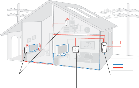
The HomePortal® iNID (intelligent Network Interface Device) system includes three
components: the i3822V (outside unit), the iPSU (power supply unit), and the i38HG
(inside unit). These components depend on each other and do not have standalone
functions. These components provide triple-play service (voice, data, and video) to the
subscriber’s home.
i3822V (outside unit)
The i3822V is the gateway that acts as the network interface device. It is installed by
the service provider technician on the outside of the home. The i3822V includes a
broadband interface and high-speed coaxial and phone line network capabilities to
deliver data service to the home. The i3822V has two accessible areas, one for
service provider personnel and the other for subscribers.
NID
ETHERNET
WIRELESS
LINE 1
LINE 2
SERVICE
POWER
BROADBAND
i38HG
BATTERYBATTERYPOWERPOWER
SILENCE ALARMSILENCE ALARM
VDSL
Coax
In home wiring
CAT 3
NID
ETHERNET
WIRELESS
LINE 1
LINE 2
SERVICE
POWER
BROADBAND
i38HG
i38HG (inside unit) i3822V (outside unit)
iPSU (power supply unit)
Chapter 1 Introduction 7
Subscriber access
The subscriber area is accessible by the homeowner. This panel displays indicators
that show the operational status of the i3822V. Some indicators on the i3822V have
the same functions as the indicators on the i38HG (inside unit). The subscriber area is
fastened with a screw that can be unfastened with any flat-blade screwdriver. To
prevent any unauthorized access, the subscriber area can be locked with any
common household locking devices (such as a padlock or a combination lock).
Note: Call your service provider if any i3822V indicators signify failures. Do not
attempt to repair the i3822V. The unit must be serviced by your service provider.
POWER
-
+
8 Chapter 1 Introduction
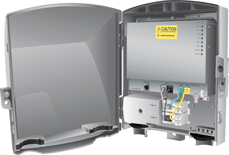
Service provider access
The service provider Telco access area is locked. Service provider personnel can
access this area by removing the Telco access cover. The i3822V has two cable
entries to provide wiring from the service provider and to inside the home. The left
entry provides the VDSL cable connection from the service provider to the i3822V.
The right entry provides a coaxial wiring connector that feeds the inside of the home
and a power connection for the power supply unit. It also provides connection access
to the customer premises phone wiring.
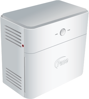
iPSU (power supply unit)
The Power Supply Unit (iPSU) supplies power to the i3822V and is installed by the
service provider. Unlike the i3822V, the iPSU must be installed in a sheltered area,
either inside the garage or home. If the iPSU is equipped with a backup battery, during
a temporary AC power outage, the power source is switched to the battery without any
interruption to subscribed services. When the AC power is restored, the power source
is switched back to the AC power supply. The switchover between the AC power
supply and the battery is automatic and without interruption of service.
DSL LINE 2DSL LINE 1
FROM C O
LINE 1
LINE 2
COAX
ETHERNE T
TELCO ACCES S
CO LINE 2
CO LINE 1
TO TEST VOICE SERVICE PLUG IN WORKING PHONE
POWER
Telco access cover
Left entry Right entry
Chapter 1 Introduction 9
The iPSU itself requires no regular maintenance; however, the battery inside the iPSU
requires periodic replacement. See “Replacing the battery” on page 35 for
instructions to replace the backup battery.
Note: The battery provides power for voice services during a power outage.
Subscribers are responsible for monitoring and replacing the battery when needed.
The service provider does not monitor the battery and is not responsible for its
replacement.
i38HG (inside unit)
The i38HG is the unit that goes inside the subscriber’s home and can be installed by
the subscriber or by the service provider. Working together with the i3822V, the i38HG
is a home networking hub that provides an 802.11b/g Wi-Fi access point and Ethernet
switch functions for connecting personal computers and other in-home networked
devices to the service provider’s network. The i38HG has four Ethernet ports for
directly connecting computers or devices.
The i38HG includes an integrated wireless access point to provide wireless
connectivity throughout the home or office. High-powered wireless technology virtually
eliminates wireless “coldspots” in the home. The i38HG high-power 400mW
transmitter ensures that you benefit from increased wireless bandwidth throughout the
coverage area. In addition, the i38HG employs a special triple antenna design. The
third antenna is used only for transmitting packets, thus mitigating the power loss
associated with switching the antenna use back and forth between transmit and
receive. This results in greater access point sensitivity, as antenna placement can be
better optimized with a dedicated set of receive-only antennas.
To expand the wireless coverage in a home or add additional Ethernet ports in
different locations in the home, you can connect multiple i38HG devices to different in-
home phone jacks. Each i38HG is automatically configured to operate on the same
wireless network, and the devices can be centrally configured and managed at
http://gateway.2wire.net.
POWER
SILENCE ALARM
BATTERY

10 Chapter 1 Introduction
Note: Contact the service provider for information about implementing multiple i38HG
devices.
Gathering items for installation
The installation chapters for the i3822V and iPSU components are written primarily for
technicians who are installing the i3822V and connecting it to the power supply unit.
The installer should be familiar with the appropriate VDSL test tools, installation
practices, and service verification procedures before starting this installation.
The following items are required for installing the i3822V outside unit and the iPSU
unit:
•5/32” tamper proof hex screwdriver (booth wrench)
•Phillips screwdriver
•Flat-blade screwdriver
•5/16” nut head screwdriver
•1/8” drill
•3/8” hex or flat-blade screwdriver
•1/4” nut or flat-blade screwdriver
•Torque wrench
•Computer
•Electrical outlet tester
NID
ETHERNET
WIRELESS
LINE 1
LINE 2
SERVI CE
POWER
B
R
OA D B A N D
i38HG
Chapter 1 Introduction 11
•Test toolkit (VDSL test set)
•Mounting screws and washers for the i3822V
– two #10x2 1/2” hex tap screws
– two #10 regular flat washers
– two rubber washers
•Two SAE #10 mounting screws for the power supply unit

12 Chapter 2 Installing the i3822V (Outside Unit)
Installing the i3822V
(Outside Unit) 2
Use the information in this chapter to install the i3822V component on the outside of
the subscriber’s home.
Installation overview
To install the i3822V component, you will do the following:
•“Mounting the i3822V” on page 12
•“Connecting network cables” on page 14
•“Connecting power supply wires” on page 17
•“Connecting the coaxial cable” on page 19
•“Connecting the insulation-displacement connectors” on page 20
•“Securing the i3822V” on page 22
WARNING: To reduce the risk of fire, use 24 AWG or larger telecommunication line
wire.
Mounting the i3822V
The i3822V is housed in a protective casing that can be mounted on any flat surface
(wood, brick, or stone) of an outside wall. To mount the i3822V:
1. Locate a wood stud in an exterior wall where you want to mount the i3822V.
2. Use the 5/32” tamper-proof hex screwdriver to loosen the screw on the cover.
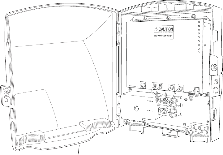
Chapter 2 Installing the i3822V (Outside Unit) 13
3. Open the cover at a 90 angle or greater, lift off the cover, and set it aside.
4. Mount the i3822V with the following hardware and follow the instructions on the
mounting template included with the i3822V packaging.
– 2 #10x2 1/2” hex tap screws
– 2 #10 regular flat washers
– 2 rubber washers
Note: Mount the i3822V vertically for convection cooling. Allow sufficient space so
the i3822V front cover can be opened for connection and testing purposes as well
as for subscribers to place a lock on the right side of the device.
TELCO
PO WER
VDSL 1
VDSL 2
DATA
COAX
LINE 1
LINE 2
ETHERNET
BATTER Y
TR
TR
TR TR
TO TEST VOICE SERVICE PLUG IN WORKING PHONE
FROM CO
LINE 1
DSL LINE 1 DSL LINE 2
ETHERNET LINE 2
POWER
-
+
cover
14 Chapter 2 Installing the i3822V (Outside Unit)
Use appropriate fasteners to secure the i3822V when it is mounted on a brick or stone
surface.
Connecting network cables
The i3822V can accommodate up to two pairs of inside wiring per line. If the
subscriber requires more than two lines (any combination of VoIP or PSTN), the lines
must be bridged between a normal Network Interface Device (NID) and the i3822V’s
connectors. If the home runs are on the outside of the home, terminate them before
connecting to the i3822V.
Note: The bridging procedures are outside the scope of this document.
The VDSL area is protected with a cover to prevent subscriber access. There are two
pairs of binding posts for attaching the i3822V to two separate pairs of Cat 3 telephone
wiring from the network that carry PSTN and VDSL2. The connection to the second
pair is required to enable a second PSTN line and VDSL pair bonding (when
available).
Note: The VDSL area is accessible only to the telco personnel.
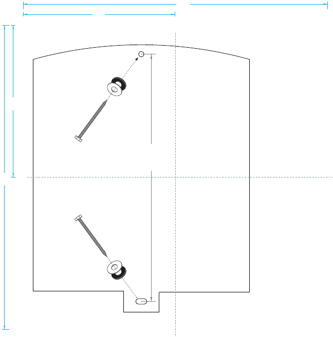
SIDE
TOP
TEMPLATE
KEYHOLE
KEYHOLE
12 3/
16”
15”
15”
7.5”
7.5”
fold
fold
Chapter 2 Installing the i3822V (Outside Unit) 15
To connect the network cables:
1. Unfasten the screw that secures the Telco access cover with a 5/32” tamper-proof
hex screwdriver (booth wrench).
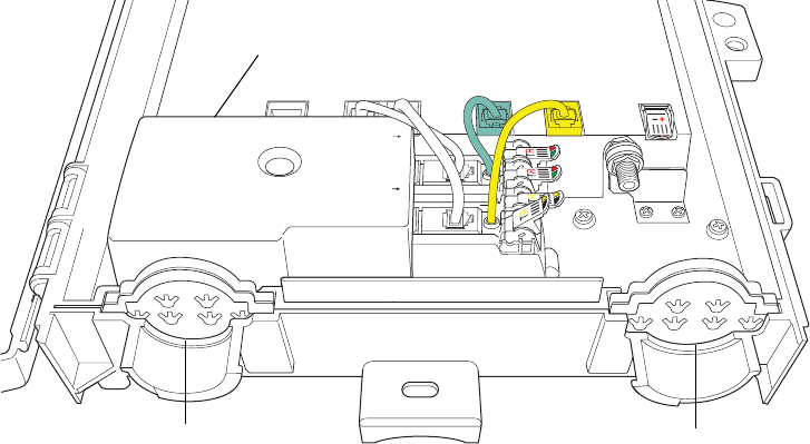
2. Cut two openings on the left grommet entry for the network cable and the 10 AWG
ground wire to fit through.
Note: Use an appropriate tool to cut or punch through the grommet. Make the cuts
just large enough for the cables to fit through. The grommet pad prevents insects
from entering the inside of the unit. Make sure to seal any extra gaps on the cuts
using the approved sealant that complies to your local requirements.
WARNING: You must permanently connect the ground lug to an approved Telephone
Ground. (Refer to the appropriate local installation practice).
3. Insert the 10 AWG ground wire through one of the openings of the grommet entry
and connect it to the ground lug in the lower left portion of the i3822V.
DSL LINE 2DSL LINE 1
FROM C O
LINE 1
LINE 2
COAX
ETHERNE T
TELCO ACCES S
CO LINE 2
CO LINE 1
TO TEST VOICE SERVICE PLUG IN WORKING PHONE
POWER
Telco access cover
Grommet entry
ETHERNE T
TELCO ACCESS
Ground lug
16 Chapter 2 Installing the i3822V (Outside Unit)
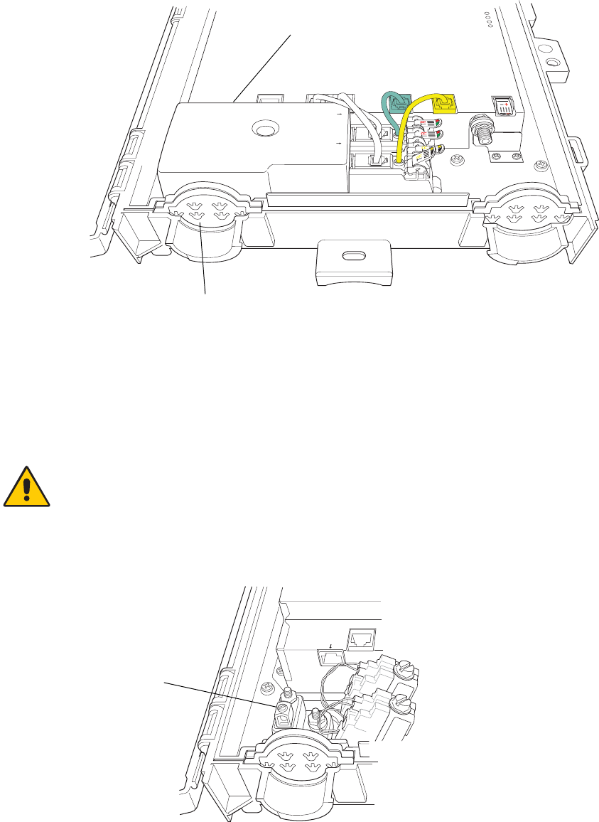
4. Insert the drop wire from the network through the other opening on the grommet
entry.
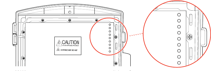
5. Make sure that the red and green wires installed in the top round holes on each
station protector are firmly seated in the slots along the top of the holes. This
prevents them from dislodging when the nut on the top of the station protector is
loosened.
6. Use a 3/8” hex or flat blade screwdriver to loosen one of the station protectors by
turning it counter-clockwise to a full upright position.
ETHERNE T
TELCO ACCESS
Slot
DSL LINE 2DSL LINE 1
FROM C O
LINE 1
LINE 2
COAX
ETHERNET
TELCO ACCESS
TO TEST VOICE SERVICE PLUG IN WORKING PHONE
POWER
VDSL area
Chapter 2 Installing the i3822V (Outside Unit) 17
Note: Do not remove the protective gel-filled insulation around the holes; it acts as
a moisture barrier and prevents unwanted small particles from having direct
contact with the wires.
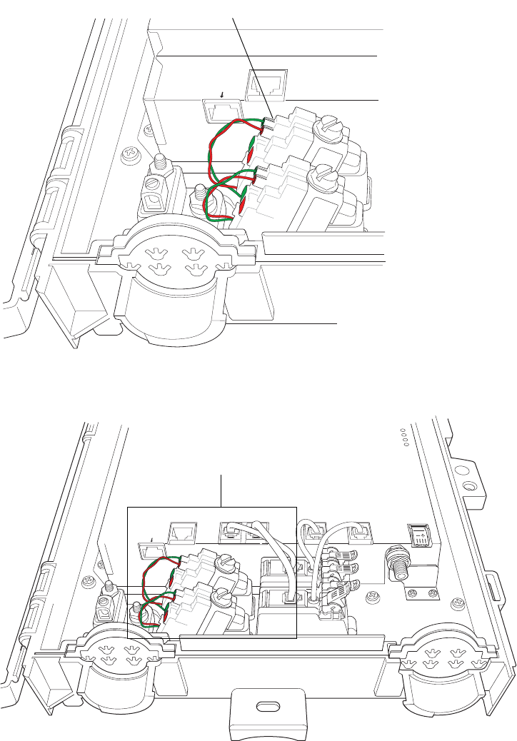
7. Insert approximately 1-1/2 inches of the un-stripped color-coded wire pair of the
VDSL lines from the network provider through the corresponding color-coded
holes of the station protectors, green to tip and red to ring.
Note: You may feel an initial resistance when inserting the wires into the protector.
Do not stop there. If you do, the connectors might close on the insulation, but no
contacts are made. Make sure that the inserted wire ends are straight and have no
curls on them. If the wires are bent upward or curled when inserted, they will not
make proper contact. This may result in the wires passing the pull test even
though there is no connection.
8. Peek through the side of the station protector and make sure that the wires have
pierced the gel-filled insulation and that contacts are made.
9. Hold the two wires in place; use a 3/8” hex or flat blade screwdriver and turn
clockwise to tighten the station protector.
10. Tug gently at the inserted wires to make sure that they are securely seated.
11. Repeat Step 6 through Step 10 for the second VDSL pair.
12. Secure all cables and wires to the strain relief bar at the top of the grommet.
13. Attach the Telco access cover that you removed in step 1 with a 5/32” tamper-
proof hex screwdriver (booth wrench).
Connecting power supply wires
This section provides instructions for connecting the power supply wires to the i3822V.
The power supply connector on the i3822V and the iPSU are colored with the same
polarity: red is positive and black is negative. If the phone cable that you are using
does not have red and black wires, make note of the color coding on the wires
connected to the red and black holes in the i3822V power connector. The same color
wire connected to the red hole in the i3822V power connector must be connected to
the red terminal in the iPSU, and the same color wire connected to the black hole in
the i3822V power connector must be connected to the black terminal in the iPSU.
The cable connecting the iPSU and the i3822V must be a dedicated pair and must not
appear at any phone jacks in the home. Run a new cable between the iPSU and the
i3822V if no dedicated pair is available. The cable must be 24 AWG and can be a
maximum of 100 feet long. The power pair must not have any impairments such as
shorts to ground.
Note: Do not use a wire thinner than 24 AWG; it compromises the maximum wiring
length and the battery backup duration.
18 Chapter 2 Installing the i3822V (Outside Unit)
CAUTION: When connected, the i3822V receives power from the iPSU. Make sure
that the AC power adapter and the battery on the iPSU are not connected, or an
electrical shock may result.
To connect power supply lines:
1. Cut an opening on the right grommet entry for the power supply line to fit through.
Note: Use an appropriate tool to cut or punch through the grommet. Make the cut
just big enough for the line to fit through. The grommet prevents insects from
entering the inside of the unit. Make sure to seal any extra gaps on the cuts.
2. Insert the power supply line through the opening of the grommet entry.
Note: Do not remove the protective gel-filled insulation around the holes; it acts as
a moisture barrier and prevents unwanted small particles from having direct
contact with the wires.
3. Lift up the POWER connector plastic rocker tab to expose the color-coded holes
on the right side of the unit.
4. Insert the un-stripped color-coded power supply wire pair as far as it can go into
each hole that matches the wire color: red is positive and black is negative.
You may feel an initial resistance when inserting the wires into the connector. Do
not stop there. If you do, the connectors might close on the insulation, but no
contacts are made.
Make sure that the wires have pierced the gel-filled insulation and that the inserted
wire ends are straight and have no curls on them. If the wires are bent upward or
curled when inserted, they will not make proper contact. This may result in the
wires passing the pull test even though there is no connection.
Note: The power supply insulation-displacement connector (IDC) on the i3822V
and the iPSU are colored with the same polarity. Make sure to maintain polarity:
red is positive, black is negative. If wires are reversed, the i3822V will not power
up.
Power connector
Chapter 2 Installing the i3822V (Outside Unit) 19
5. Press the tab downward to lock the wires into the connector.
6. Tug gently at the inserted wires to make sure that they are securely seated.
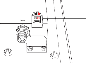
Connecting the coaxial cable
To connect the coaxial cable to the i3822V:
1. Cut an opening on the right grommet entry for the coaxial cable to fit through.
Note: Use an appropriate tool to cut or punch through the grommet. Make the cut
just big enough for the cable to fit through. The grommet prevents insects from
entering the inside of the unit. Seal any extra gaps on the cuts.
2. Insert the cable through the opening on the grommet entry.
DSL LINE 2NE 1
FROM CO
LINE 1
LINE 2
COAX
O LINE 2
CO LINE 1
TO TEST VOICE SERVICE PLUG IN WORKING PHONE
POWER
20 Chapter 2 Installing the i3822V (Outside Unit)
3. Connect the coaxial cable to the COAX connector located on the right side of the
unit.
4. Tighten the coaxial cable with a torque wrench.
5. Connect the other end of the cable from the i3822V to the IN port of the coaxial
splitter.
Note: The COAX connector is very sensitive to loose or improperly terminated
connectors; tighten it with a torque wrench at a minimum 15 in-lb but do not exceed
20 in-lb.
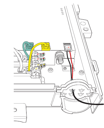
Connecting the insulation-displacement
connectors
The subscriber part of the network access area has two customer bridge modules,
each with a pair of insulation-displacement connectors (IDCs). Each bridge module
supports a separate line and can connect to up to two inside wire pairs.
Each IDC is connected as a separate phone line consisting of two wires. Line 1
(green/red) is used for HPNA over twisted pair for data distribution and voice traffic
(PSTN or VoIP) inside the home. Line 2 (black/yellow) is used for voice traffic (PSTN
or VoIP).
1. Cut an opening on the right grommet entry for the PSTN lines to fit through.
Note: Use an appropriate tool to cut or punch through the grommet. Make the cut
just big enough for the cable to fit through. The grommet prevents insects from
entering the inside of the unit. Seal any extra gaps on the cuts.
DSL LINE 2E 1
FROM C O
LINE 1
LINE 2
COAX
O LINE 2
O LINE 1
TO TEST VOICE SERVICE PLUG IN WORKING PHONE
POWER
COAX connector
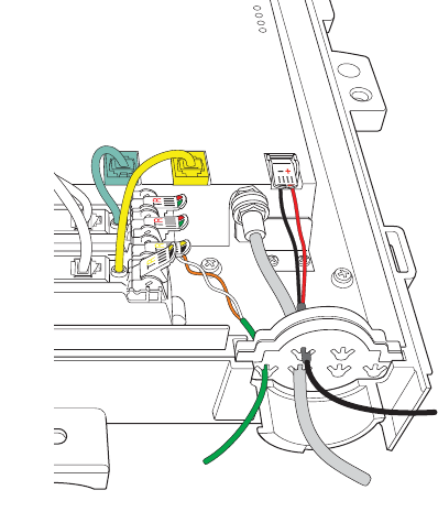
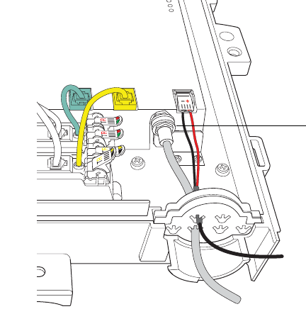
Chapter 2 Installing the i3822V (Outside Unit) 21
2. Insert the subscriber’s inside wire through the opening of the grommet entry.
Note: Do not remove the protective gel-filled insulation around the holes; it acts as
a moisture barrier and prevents unwanted small particles from having direct
contact with the wires.
3. Lift up one of the color-coded plastic rocker tabs of the IDC and insert
approximately 1-1/2 inches of an un-stripped wire into each hole that matches the
wire color of the tab.
You may feel an initial resistance when inserting the wires into the tabs. Do not
stop there. If you do, the connectors might close on the insulation, but no contacts
are made. The wire needs to be inserted past that point so that it is completely
through the vertical metal piece and can be clamped into place. Make sure that the
inserted wire ends are straight and have no curls on them. If the wires are bent
upward or curled when inserted, they will not make proper contact.
If the subscriber’s wiring colors do not match these tab colors, inspect how a
phone jack inside the home is wired and attach the colored wires similarly to this
device. A typical example would be white with blue strip to green; blue with white
stripe to red; white with orange stripe to black; orange with white stripe to yellow.
4. Look through the plastic and make sure that the wire passes through the IDC
blade.
5. Press down the tab to lock the wire.
6. Tug gently at the wires to make sure that they are securely seated.
7. Repeat Step 3 through Step 6 for the second line.
8. Secure all cables and wires to the strain relief bar at the top of the grommet.
DSL LINE 2E 1
FROM CO
LINE 1
LINE 2
COAX
LINE 2
O LINE 1
TO TEST VOICE SERVICE PLUG IN WORKING PHONE
POWER
22 Chapter 2 Installing the i3822V (Outside Unit)
Securing the i3822V
To secure the i3822V unit:
1. Align the cover at a 90 angles to the unit.
2. Push the cover downward toward the locking area on the left of the i3822V.
3. Fasten the screw that secures the cover with the 5/32” tamper-proof hex
screwdriver.
Note: Make sure that the cover is securely fastened to prevent any unauthorized
access.
Chapter 3 Installing the iPSU (Power Supply Unit) 23
Installing the iPSU
(Power Supply Unit) 3
This chapter provides instructions to install the Intelligent Power Supply Unit (iPSU) in
a protected location and connect it to the i3822V component.
Installation overview
To install the iPSU component, you will do the following:
•“Preparing the installation site” on page 24
•“Mounting the power supply unit” on page 25
•“Connecting the power cables” on page 27
The intelligent Power Supply Unit (iPSU) delivers DC power to the i3822V using a
single dedicated pair of 24 AWG (minimum) phone cable. The power supply operates
on 120V AC, 60 Hz power, and supplies 29V DC nominal to the i3822V.
If the power supply unit is equipped with a battery backup, during a temporary AC
power outage, the power source is switched to the battery without interruption of
service. When the AC power is restored, the power source is switched back to the AC
power supply. The switchover between the AC power supply and battery is automatic
and instantaneous.
24 Chapter 3 Installing the iPSU (Power Supply Unit)
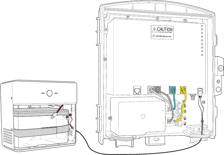
The following figure shows the connection between the power supply unit and i3822V.
Preparing the installation site
Unlike the i3822V, the iPSU must be installed in a sheltered area, either inside the
garage or home. The iPSU with a battery installed weighs approximately 11 pounds.
Make sure that the selected wall stud is strong enough to support the weight.
Locating a proper site
You can mount the iPSU on any flat surface (wood, brick, or stone) and at any height
level, from eye to floor level. Unless it is demanded by the subscriber that the iPSU be
mounted on the floor level, mount the iPSU above the floor level and away from any
areas with a potential for standing water.
The life of the battery is affected by the local environment; select a site that is away
from excessive heat, machinery, and vibration. Locate a stud wall inside the home or
garage that is within eight feet of the nearest electrical outlet (the length of the
supplied power adapter) and strong enough to support 11 pounds (the weight of iPSU
with a battery installed).
Note: Do not use an extension cord.
The iPSU contains live electronics. Any standing water that is above four inches from
the bottom edge of the iPSU can damage the iPSU wiring, which might affect the
performance of the i3822V. The lead-acid battery is sealed and will not be damaged
by the water exposure.
CO LINE 1
CO LINE 2
–+
POWER
SILENCE ALARM
BATTERY
Chapter 3 Installing the iPSU (Power Supply Unit) 25
Testing the electrical outlet
Test the electrical outlet you intend to use with an electrical outlet tester to ensure that
it is working.
Mounting the power supply unit
This section assumes that the i3822V has been mounted and that the power supply
line on the i3822V has been connected. An 8-foot AC power adapter is shipped with
the power supply unit. Allow slack (about 2 inches) for the power plug when mounting
the power supply unit.
Note: Unless you are advised from the battery manufacturer, do not install batteries
measuring less than 12.75V. Measure the open circuit battery voltage to make sure
that it has not significantly discharged before installation.
To mount the iPSU:
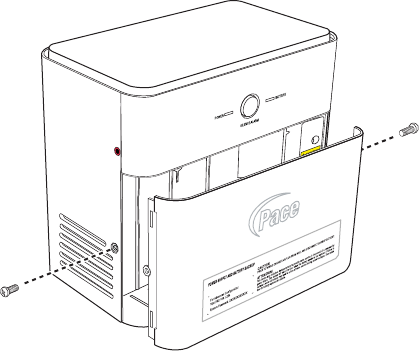
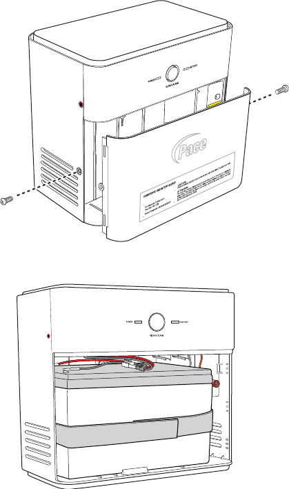
1. Use a Phillips screwdriver to unfasten the two screws (one on each side) securing
the power supply unit cover and put them in a safe place until they are needed.
CAUTION: The iPSU with a battery installed weighs approximately 11 pounds. To
prevent potential personal injury or equipment damage, mount the iPSU to a wall stud
that is strong enough to support the weight.
Remove screws from both
sides of the unit to remove
the front cover.
26 Chapter 3 Installing the iPSU (Power Supply Unit)
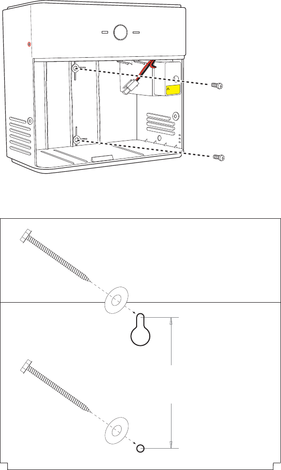
2. Place the back of the iPSU against the wall stud.
3. Mark and drill holes for the mounting screws using the template that is included
iPSU package.
4. Fasten the iPSU to the wall using SAE #10 (or equivalent) mounting screws.
POWER
SILENCE ALARM
BATTERY
CAUTION
POTENTIAL SHOCK
SIDE
TOP
TEMPLATE
3 9/16”
KEYHOLE
KEYHOLE
Chapter 3 Installing the iPSU (Power Supply Unit) 27
Connecting the power cables
After the iPSU is mounted, connect the following three sets of cables to begin
supplying power to the i3822V:
•The power line between the iPSU and i3822V
•The AC power cord to the AC outlet
•The battery cable
Connecting the power supply to the i3822V
To connect the iPSU unit to the i3822V:
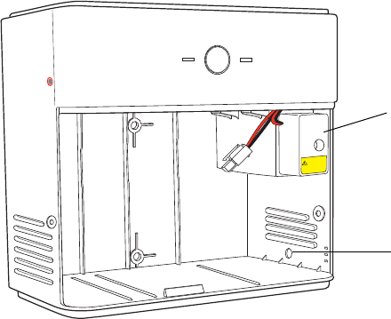
1. Use a Phillips screwdriver to unfasten the screw securing the power terminal
cover.
2. Insert the end of the power cable from the i3822V through the round opening on
the right panel of the iPSU.
3. Strip 3/8” to 5/8” on the power cable pair to expose the wires.
4. Connect the color-coded wires that correspond to the color-coded binding posts of
the power terminals to the outside unit.
Note: Make sure to maintain polarity: red is positive, black is negative. If the wires
are reversed, the i3822V will not power up.
5. Place the cover back on the power supply post and make sure that it is properly
seated.
Note: Do not pinch the wires.
6. Fasten the screw to secure the power terminal cover.
POWER
SILENCE ALARM
BATTERY
CAUTION
POTENTIAL SHOCK
Power terminal cover
Opening
28 Chapter 3 Installing the iPSU (Power Supply Unit)
Connecting the iPSU to the electrical outlet
Insert the AC power plug into an electrical outlet. Observe the POWER indicator on
the iPSU; it should light red (if power is present) and turn to green within two minutes.
Chapter 4 Verifying the i3822V and iPSU Installations 29
Verifying the i3822V and
iPSU Installations 4
This chapter provides instructions to verify the installation of the i3822V (outside unit)
and the Intelligent Power Supply Unit (iPSU). It also includes sections that provide
procedures for connecting the iPSU backup battery and general iPSU maintenance.
Verification overview
To install the iPSU component, you will do the following:
•“Starting the i3822V component” on page 29
•“Interpreting the i3822V indicators” on page 30
•“Enabling the ETHERNET port” on page 31
•“Interpreting the iPSU indicators” on page 32
•“Connecting the backup battery” on page 33
•“iPSU maintenance” on page 34
•“Replacing the power supply unit” on page 37
Starting the i3822V component
After you connect the necessary cables, and connect the i3822V to the power supply
unit, the i3822V component powers up automatically. For information about installing
the power supply unit, see “Connecting the power cables” on page 27.
30 Chapter 4 Verifying the i3822V and iPSU Installations
Interpreting the i3822V indicators
The following table describes the indicators on the i3822V. The indicators on the
component behave differently depending on the current state of the gateway.
Note: The indicators on the i3822V are not active until you connect the i3822V to the
power supply unit. For information about installing the power supply unit and
connecting it to the i3822V, see “Installing the iPSU (Power Supply Unit)” on page 23.
Indicators Description
POWER The POWER indicator turns red when the power is first
applied, and changes to green within two minutes of power
application.
•Solid green. The power is on and initialization has been
completed successfully.
•Flashing green. The iNID is booting.
•Red. A Power-On Self-Test (POST) failure (the device is
unbootable) or another malfunction has occurred during
self initialization.
VDSL 1 and VDSL 2 These two indicators flash after 60 seconds of power
application for one to two minutes and cycle three times.
•Solid green. The broadband connection is trained.
•Flashing green. The broadband connection is being
attempted (DSL attempting to synchronize).
•Alternating flashing green and steady red. The
broadband connection failed to establish for more than
three consecutive minutes. This pattern continues until
the broadband connection is successfully established.
•Flashing red. There is no DSL signal on the line.
The BROADBAND indicator on the i38HG mirrors one or
both of the VDSL indicators, whichever is in the “best”
state.
DATA • Solid green. A device is connected (such as i38HG).
•Flashing green. There is inbound activity associated
with the data port (that is, the green LINE 1 connection).
The flickering of the light is synchronized to the actual
data traffic.
•Red. A device failed to be authenticated or successfully
connected.
POWER
VDSL 1
VDSL 2
DATA
COAX
LINE 1
LINE 2
ETHERNET
BATTERY
POWER
VDSL 1
VDSL 2
DATA
COAX
LINE 1
LINE 2
ETHERNET
BATTERY

Chapter 4 Verifying the i3822V and iPSU Installations 31
Enabling the ETHERNET port
The ETHERNET port is disabled by default. This port is used only if the subscriber has
Cat 5 wiring throughout the home that is terminated on the side of the home. It
supports other Ethernet devices, such as switches or hubs.
To enable the ETHERNET port:
1. Open a browser and enter http://gateway.2wire.net or http://172.17.0.1 as the
URL.
2. On the Settings tab, click the LAN tab, and then click Wired Interfaces.
3. Click the Auto MDIX check box to enable the ETHERNET port on the i3822V.
4. Click Save.
COAX • Solid green. A device is connected (such as a set-top
box).
•Flashing green. There is inbound activity associated with
the COAX port. The flickering of the light is synchronized
to the actual data traffic.
•Red. A device failed to be authenticated or successfully
connected.
LINE 1 and LINE 2 • Solid green. The associated voice line has been
registered with the network and is ready for use.
•Flashing green. A phone is in use on the associated
voice line.
These two indicators mirror LINE 1 and LINE 2 indicators
on the i38HG.
ETHERNET • Solid green. A device (such as a computer) is connected
to the ETHERNET port.
•Flashing green. There is inbound activity from devices
connected to the ETHERNET port. The flickering of the
light is synchronized to the actual data traffic.
BATTERY • Solid green. The AC power is connected and healthy.
•Flashing red. The backup battery is being used for
power.
Indicators Description

32 Chapter 4 Verifying the i3822V and iPSU Installations
Interpreting the iPSU indicators
The indicators on the iPSU behave differently depending on the current state of the
unit, as shown in the following table:
Indicators and
Buttons Description
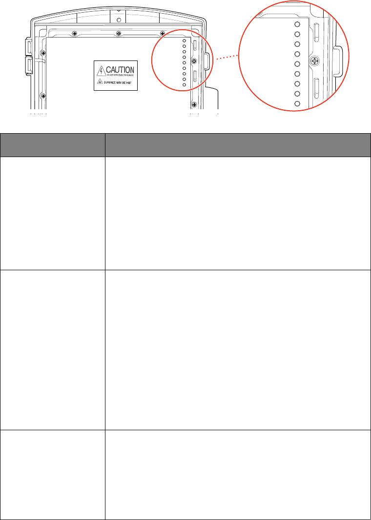
RESET Button A RESET button is located on the upper left side panel,
highlighted by a surrounding red circle. When pressed for up
to 9 seconds, the RESET button reboots the outside unit. If
the button is pressed for 10 or more seconds, it resets the
outside unit to the factory default settings. Do not press the
RESET button unless you are instructed to do so. Doing so
may reset the outside unit to the factory default settings,
which means you will lose your personal settings.
POWER • Solid green. The power supply is running on AC power.
•Off. The power supply is not receiving power from either
AC or the battery.
•Flashing red. The power is provided by the backup
battery or the outside unit is not yet communicating with
the iPSU.
SILENCE ALARM
Button The SILENCE ALARM button is located between the
POWER and BATTERY indicators.
• If AC power is interrupted for any reasons, a continuous
tone indicates that the power supply is running on the
backup battery. Pressing the SILENCE ALARM button
within 15 seconds immediately silences the audio alert.
(The tone stops automatically after 15 seconds.)
• When the battery needs replacing, a chirp sounds
intermittently unless you press the button to silence it for
12 hours. The chirp resumes after 12 hours if the battery is
not replaced.
BATTERY • Solid green. The battery is installed and functioning
properly.
•Off. No battery is installed.
•Flashing red. The battery needs to be replaced.
Note: The BATTERY indicator works properly only when the
iPSU is connected to and communicates with the i3822V.
Reset Power
Silence alarm
Battery
Chapter 4 Verifying the i3822V and iPSU Installations 33
Connecting the backup battery
CAUTION: Follow the manufacturer’s safety statements when handling the lead-acid
battery.
Note: The battery must be approved for use in the iPSU.
Unless you receive an advisement from the battery manufacturer (they are liable for
warranty service), do not install batteries measuring less than 12.75V, which
represents a charge of approximately of 80% of the rated capacity. Measure the open
circuit battery voltage to make sure that it has not significantly discharged before
installation.
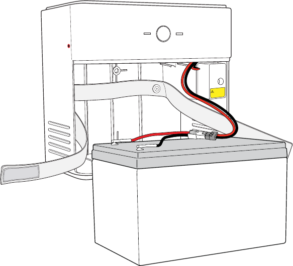
To connect the backup battery:
1. Verify that the AC power plug is plugged into a working electrical outlet.
2. Use a Phillips screwdriver to unfasten the two screws (one on each side) securing
the power supply unit cover and put them in a safe place until they are needed.
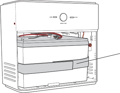
3. Insert the battery gently into the iPSU.
Note: Make sure to place the battery inside the raised lip of the unit.
4. Connect the backup battery connector from the iPSU to the connector on the
battery.
5. Observe the BATTERY indicator on the iPSU; it should light green.
POWER
SILENCE ALARM
BATTERY
CAUTION
POTENTIAL SHOCK
34 Chapter 4 Verifying the i3822V and iPSU Installations
Note: A faulty battery is indicated if the BATTERY indicator does not light green
within five minutes (assuming the iPSU is plugged into a functioning AC power
outlet).
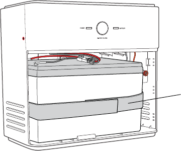
6. Secure the battery with the safety strap.
7. Place the housing cover over the unit and press gently on it until it snaps into
place.
8. Fasten the cover with the screws you removed earlier.
iPSU maintenance
The iPSU needs no maintenance other than regular battery inspection and
replacement. If the power supply unit is equipped with a backup battery, it continues to
provide power to the i3822V during a power outage so that a phone call can be made
in the event of an emergency. During a temporary AC power outage, the iPSU power
source is switched to the battery without interruption of services. When the AC power
is restored, the iPSU power source is switched back to AC power. The switchover
between the AC power and the battery is automatic and instantaneous.
Note: Reserve the battery charge during a power outage. Do not access the Internet
when the power is running on the battery. Doing so will discharge the battery at a
much faster rate and shorten the voice service time.
You are solely responsible for periodically replacing this battery to provide
uninterrupted voice services during a power outage. Your service provider does not
monitor the battery and is not responsible for its replacement.
Attach safety strap
Chapter 4 Verifying the i3822V and iPSU Installations 35
Replacing the battery
The battery is rated for a service life of up to five years, which varies depending on
operational and environmental conditions. The battery life expectancy depends on the
operating environment as temperature extremes shorten the battery life.
The battery is specifically designed to use with the iNID system. Refer to the label
inside the front cover of the iPSU or contact your service provider for battery
replacement information.
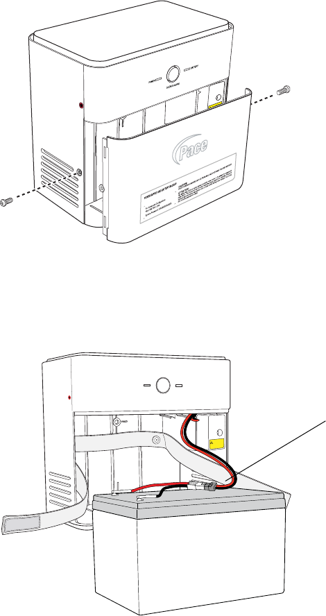
To replace the battery:
1. Use a Phillips screwdriver to unfasten two screws (one on each side) securing the
power supply battery cover, and put them in a safe place.
2. Adjust the battery cable and battery cable connector so that it is visible (located on
top of the backup battery).
3. Press down on the tension springs and pull to disconnect the battery cable
connector from the battery cable.
4. Release the safety strap securing the battery.
Remove screws from both sides
of the unit to remove the front
cover.
POWER
SILENCE ALARM
BATTERY
CAUTION
POTENTIAL SHOCK
Tension springs
36 Chapter 4 Verifying the i3822V and iPSU Installations
5. Remove the old battery from the housing and put it safely aside.
Note: Be careful when removing the battery; it is heavy.
6. After removing the old battery, verify that the BATTERY indicator is completely
extinguished (not green or blinking red).
Note: It can take up to three minutes before the BATTERY indicator is completely
off and the Power Supply Unit is ready to accept the new battery.
7. Insert the new battery gently into the housing.
Note: Be sure to place the battery inside the raised bottom edge of the case.
8. Connect the battery cable connector to the battery cable.
9. Observe the BATTERY indicator on the iPSU, it should light green when the
i38HG and i3822V are communicating properly.
Note: A faulty battery is indicated if the BATTERY indicator does not light green
within five minutes (assuming the iPSU is plugged into a functioning AC power
outlet).
10. Secure the battery with the safety strap.
11. Place the housing cover over the unit and press gently on it until it snaps into
place.
12. Fasten the cover with the two screws you removed earlier.
Note: If you have disabled the alert earlier, make sure to enable the alert.
Disabling the alert
By default, the audible alert is enabled to warn you when the battery is exhausted. It is
recommended that you do not disable the audible alert unless you intend to replace
the battery within a short time. A chirping tone sounds when the battery is exhausted
and needs replacing. The duration of the chirping sound is 0.2 seconds and it
happens once every five seconds. You can turn off the chirping sound to disable the
alert for 12 hours or permanently.
Attach safety strap
Chapter 4 Verifying the i3822V and iPSU Installations 37
If you disabled the alert and did not replace the backup battery in a timely manner, you
may not have voice services in case of emergency during an AC power outage.
CAUTION: Disable the audio alert with caution. The battery must be replaced within a
short period of time after the audio alert begins indicating a bad battery. The automatic
battery backup feature may not work during an AC power outage, causing the voice
and data services to stop.
To disable the alert:
1. Open a browser and enter http://gateway.2Wire.net as the URL.
2. On the Settings page, click System Info, and then click Battery Backup.
3. Click Disable Alert for 12 hours to turn off the low-battery notification or deselect
the Enable check box to disable the alert permanently.
4. Click Save.
Enabling the alert
To enable the alert:
1. Open a browser and enter http://gateway.2Wire.net as the URL.
2. On the Settings page, click System Info, and then click Battery Backup.
3. Click the Enable check box to enable the battery audible alert.
4. Click Save.
Replacing the power supply unit
The Intelligent Power Supply Unit (iPSU) provides power to the i3822V (iNID Outside
Unit). When the iPSU is disconnected from the i3822V, all Internet access and data
traffic will be stopped until power is restored.
Note: After the iPSU is replaced, the old system password is automatically configured
to the new iPSU; therefore, no reconfiguration is required. Through the gateway user
interface, you can set a custom password to match the one printed on the iPSU label.
38 Chapter 4 Verifying the i3822V and iPSU Installations
To replace the iPSU:
1. Disconnect the iPSU AC power plug from the electrical outlet.
2. Use a Phillips screwdriver to unfasten two screws (one on each side) securing the
power supply unit cover.
3. Loosen the battery safety strap.
4. Lift the backup battery out from the iPSU.
Remove screws from both sides
of the unit to remove the front
cover.

Chapter 4 Verifying the i3822V and iPSU Installations 39
5. Disconnect the backup battery connector from the iPSU to the connector on the
battery.
6. Unfasten the screw securing the power terminal cover.
7. Disconnect the power supply to the i3822V.
8. Loosen the mounting screws and dismount the iPSU.
9. Follow the procedures outlined in the “Installation overview” on page 23 to install a
new iPSU.
POWER
SILENCE ALARM
BATTERY
CAUTION
POTENTIAL SHOCK
40 Chapter 5 Installing the i38HG (Inside Unit)
Installing the i38HG
(Inside Unit) 5
The i38HG is the unit that goes inside your home and can be installed by you or your
service provider. The i38HG includes an integrated wireless access point to provide
wireless connectivity throughout the home or office. It is a home networking hub that
provides an 802.11b/g Wi-Fi access point and Ethernet switch functions for
connecting personal computers and other in-home networked devices to the service
provider’s network.
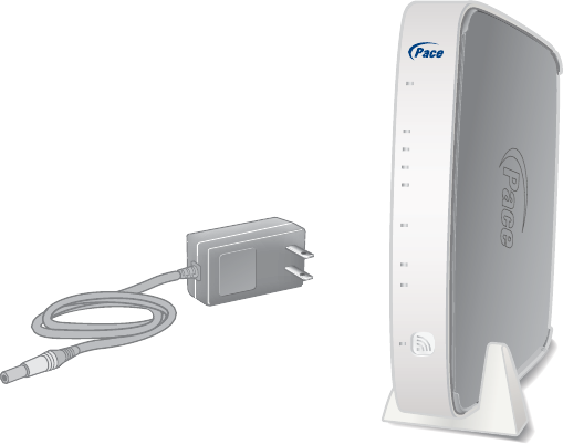
Before installing the i38HG, review the package contents and ensure that you have
available the items shown below.
Note: The i38HG and the stand are packaged separately in the container. You should
place the i38HG on the stand.
NID
ETHERNET
WIRELESS
LINE 1
LINE 2
SERVI CE
P
O
WER
B
R
O
ADBAND
i38HG
Power adapter
i38HG
Chapter 5 Installing the i38HG (Inside Unit) 41
Gathering items for installation
Installation of the i38HG requires the following items:
•A gateway and stand
•A power adapter
•A data cable (phone cable)
Optional installation items include:
•An Ethernet cable, if you are connecting a computer directly to the gateway
Installation overview
To install the i38HG component, you will do the following:
•“Finding a suitable location” on page 41
•“Connecting the data cable” on page 42
•“Connecting the power adapter” on page 43
•“Connecting your computer to the i38HG” on page 43
•“Configuring non-Pace wireless adapters” on page 44
•“Understanding the i38HG indicators” on page 45
Finding a suitable location
Wireless signals are affected by many items in households. Reliability and
performance are the major considerations when planning your wireless network
location.
Avoiding interference
Wireless signals are subject to interference from other electronic devices including
(but not limited to) microwave ovens, cordless telephones, and garage door openers.
Proper installation will minimize interference. Place your i38HG at least five feet from
cordless phones, microwaves, or other electronic devices to avoid potential
interference, and more than six inches away from a television to avoid audio hissing or
static.
Note: Whenever possible, use the stand provided with the i38HG and install it in the
vertical position. If that is not possible, be sure that it is installed in a place where
nothing can be stacked on the top of it. The i38HG generates substantial amounts of
heat and could possibly damage items stacked on it.
42 Chapter 5 Installing the i38HG (Inside Unit)
Avoiding obstructions
The wireless signal degrades with distance and obstructions (such as ceilings, walls,
and furniture). Consider the layout of your home or business when deciding where to
place your i38HG.
•Consider where you will use your wireless devices when placing your i38HG. In a
single-story building, place the i38HG as high and as close to each wireless
computer as possible. To minimize interference, do not place the i38HG behind
large objects or other obstructions.
•Place the i38HG in an open area where the wireless signal will not be directly
affected by surroundings. Wireless signal strength is much stronger in an open
area as opposed to an area with obstructions.
•Keep the i38HG away from any large metal objects. Because metal objects can
reflect or obstruct signals, wireless signal quality and speed may be adversely
impacted.
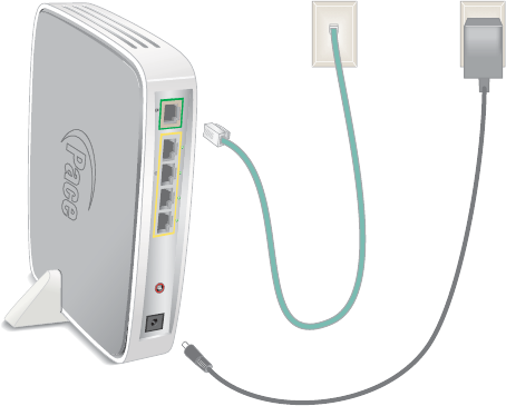
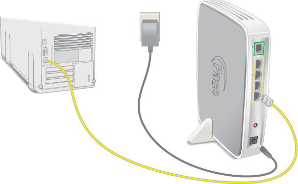
Connecting the data cable
The data cable (phone cable) carries data from the i3822V to the i38HG through your
in-home phone wiring.
Note: The phone cable is supplied by your service provider.
To connect the data cable:
1. Connect one end of the phone cable (green) to the phone wall outlet.
2. Connect the other end of the phone cable to the DATA port (green) of your i38HG.
D
ATA
P
O
WER
RESET
LOCAL ETHERNET
i38HG
Electrical outlet
Primary (main)
phone wall outlet
Chapter 5 Installing the i38HG (Inside Unit) 43
Connecting the power adapter
To connect the power adapter:
1. Connect one end of the power adapter to the POWER port of your i38HG.
2. Connect the other end of power adapter to a working electrical outlet.
3. Observe the POWER indicator; it flashes red once, followed by flashing green, then
remains solid green.
4. Check the NID, BROADBAND, and SERVICE indicators. They light green when
communication is established between the i38HG and i3822V (usually within one
minute).
Connecting your computer to the i38HG
There are two ways to connect your computer to the i38HG: through Ethernet or
wireless. With either connection, the first computer you connect to the network is used
to configure the i38HG for proper operation.
Connecting directly
You can connect up to four computers to the i38HG using the Ethernet connection.
to connect directly through Ethernet:
1. Connect one end of the Ethernet cable (yellow) to any available ETHERNET port
(yellow) on the i38HG.
2. Connect the other end of the Ethernet cable to the computer's Ethernet port. You
are now ready to start your system.
Note: The Ethernet cable is supplied by your service provider. Use a Cat 5 cable if
you need an additional or longer Ethernet cable.
DATA
POWER
RESET
LOCAL ETHERNET
Computer
Ethernet
connection
i38HG
44 Chapter 5 Installing the i38HG (Inside Unit)
Connecting through wireless
Your i38HG has an integrated wireless access point (AP) that enables you to connect
your wireless-enabled computers to your home network. By default, the i38HG is
shipped with WPA-PSK and WPA2-PSK enabled and a preconfigured network name.
You can connect multiple i38HGs in your home. When multiple APs are detected, they
are automatically synchronized across all managed access points to create a single
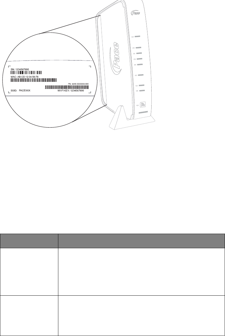
wireless network for easier device connectivity. The default service set identifier
(SSID) and wireless key is based on the last three digits of the serial number on the
first access point that was connected. If you have multiple APs installed, refer to the
label on your first installed AP only. All subsequent access points are automatically
synchronized with the default SSID or with any custom SSID you define subsequent
to initial installation.
Most laptop computers are equipped with an internal 802.11b/g card. If your computer
is not equipped with an internal card, you can install an external wireless adapter for
wireless networking. The Pace wireless adapter provides a Pace Setup Wizard that
automatically configures it to communicate with the i38HG during setup. If you are
using a non-Pace wireless adapter, you must manually configure it to communicate
with the i38HG. See “Configuring non-Pace wireless adapters” on page 44 to
configure a wireless network adapter.
Configuring non-Pace wireless adapters
If you are using a non-Pace wireless adapter, you must manually configure it to
communicate with the i38HG. This section provides instructions to configure your
adapter with WPA. You can use WEP if your wireless adapter does not support WPA;
however, this decreases the level of security provided for wireless traffic.
To install the non-Pace wireless adapter:
1. Install and configure your wireless adapter according to the manufacturer’s
instructions.
2. Use the network adapter configuration software or Windows network connection
wizard to set the network name (SSID) and encryption key (WPA).
3. Locate the SSID identified on the bottom label of your i38HG and enter it as the
network name.
Chapter 5 Installing the i38HG (Inside Unit) 45
Note: If you have multiple APs, use the last three digits of the first i38HG connected to
the network.
4. Enter the encryption key that is located inside the brackets beneath the bar code
on the bottom of your i38HG (for example, 1234567890).
Note: For Mac OS X users, you may need to enter the “$” character at the beginning
of the encryption key (for example, $1234567890).
Understanding the i38HG indicators
The indicators on the iPSU behave differently depending on the current state of the
unit, as shown in the following table:
Indicators Description
POWER The POWER indicator turns red when the power is first
applied, and changes to green within two minutes of power
application.
•Solid green. The power is on.
•Red. A Power-On Self-Test (POST) failure or another
malfunction has occurred.
ETHERNET • Solid green. A device (such as a computer) is connected to
an ETHERNET port.
•Flashing green. Inbound activity from devices is
associated with the ETHERNET port. The flickering of the
light is synchronized to the actual data traffic.

46 Chapter 5 Installing the i38HG (Inside Unit)
Replacing and removing the i38HG
The i38HG (inside unit) is a home networking hub that provides an 802.11b/g Wi-Fi
access point and Ethernet switch functions for connecting personal computers and
other in-home networked devices to the service provider’s network. The i3822V
(outside unit) is the gateway that acts as the network interface device. All wireless
configuration data is stored on the i3822V.
When you replace your i38HG, you do not need to reconfigure any settings on the new
device. All your configuration information is automatically configured to the new i38HG
when the device is initially installed and begins communicating with the i3822V. This
includes the network name and wireless key, meaning that you do not need to
reconfigure your devices during an i38HG replacement.
After replacing the i38HG, the information on the label of the i38HG will not be valid.
You can change your network name and wireless key by going to the user interface.
WIRELESS • Solid green. A device is associated with a specific access
point.
•Flashing green. There is inbound activity. The flickering of
the light is synchronized to the actual data traffic.
LINE 1 and LINE 2 • Solid green. The associated voice line has been registered
with a SIP proxy server.
•Flashing green. A telephone is off-hook on the associated
voice line.
NID Solid green. The link between the i38HG and i3822V is
healthy.
BROADBAND This indicator shows the i3822V VDSL status.
•Solid green. There is a successful broadband connection.
•Flashing green. The i3822 is attempting to establish a
broadband connection.
•Flashing green and red. The broadband connection has
failed to establish for three consecutive minutes.
•Red. There is no DSL signal.
SERVICE • Solid green. The i3822V has a WAN IP address from
DHCP and the broadband connection is up.
•Flashing green. The i3822V is attempting to be
authenticated.
•Red. The i38HG has failed to receive an IP address
assignment from the network.
Indicators Description
Chapter 5 Installing the i38HG (Inside Unit) 47
To change the network name and wireless key:
1. Open a browser and enter http://gateway.2wire.net or http://172.17.0.1 as the
URL.
2. On the Settings tab, click LAN, and then click Wireless.
3. Browse to the Network Name (SSID) text box to change the network name.
4. Browse to the Wireless Key setting and select the Use custom Wireless
Network Key option.
This setting supports a 64-bit or 128-bit encryption key.
48 Chapter 6 Troubleshooting
Troubleshooting 6
This chapter provides information about common gateway installation issues. If an
issue has more than one potential cause, the most common cause is listed first.
This section provides information and instructions to do the following:
•“Checking DSL links” on page 49
•“Checking the i3822V wiring” on page 50
•“Checking i3822V ports” on page 51
•“Checking i3822V LED status” on page 52
•“Performing an HPNA test” on page 54
•“Isolating HPNA issues” on page 54
•“Verifying voice services” on page 55
•“Verifying the iPSU connection” on page 55
•“Verifying the backup battery operation” on page 55
•“Bypassing i3822V electronics” on page 56
Chapter 6 Troubleshooting 49
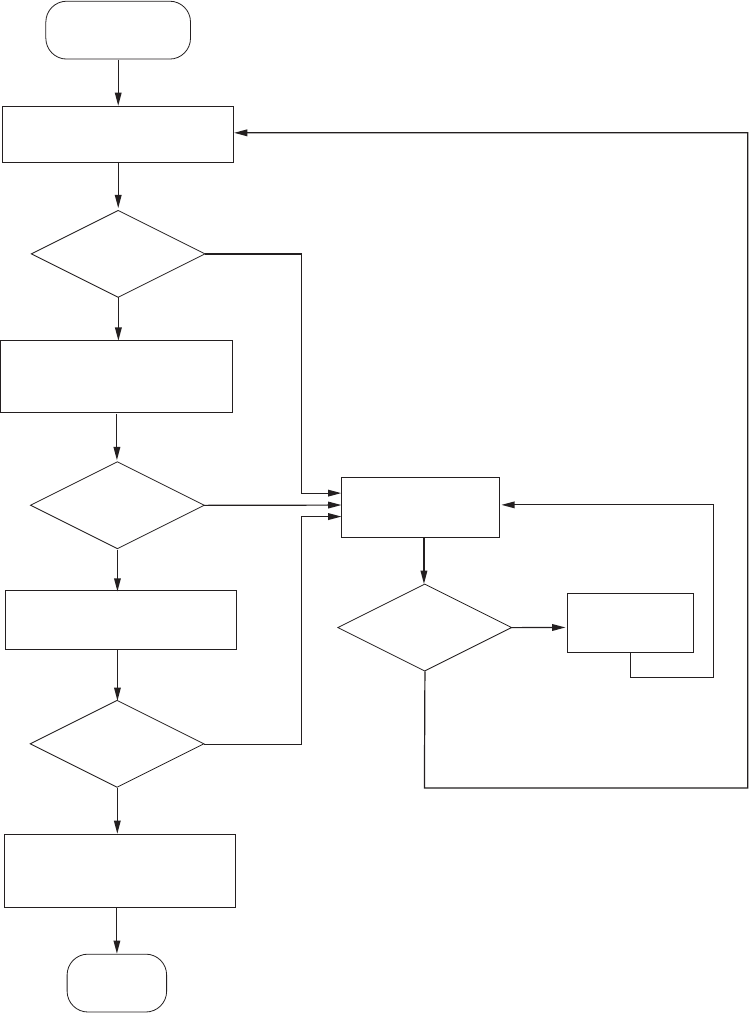
Checking DSL links
After installing the i3822V and iPSU, verify that the DSL links are functioning and that
Internet is accessible. The following figure shows a workflow diagram for testing and
troubleshooting purposes.
After the i3822v
installation
DSL connected?
1. Check iNID wiring connections.
2. Check iNID LEDs.
1. Connect to the Telco Access
Port.
2. Access GUI.
Verify DSL signals–bandwidth,
SNR, and so forth.
Go to the Broadband page and
verify that the Internet is
connected.
LEDs light green?
Signal
requirements
met?
Provisioning
issues clear?
END
Check for provisioning
issues.
Yes
Yes
Yes
Yes
No
No
No
No Resolve issues.
50 Chapter 6 Troubleshooting
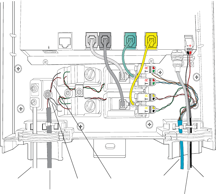
Checking the i3822V wiring
Verify that the wiring is the same as the wiring shown in the following figure.
ETHERNET
TELCO ACCESS
FROM CO
DSL LINE 1 LINE 1 LINE 2
POWER
COAX
DSL LINE 2
Grounding wire
Telco drop wire
CO Line 2 Customer
inside
wire
DC power
CO Line 1
Coaxial cable

Chapter 6 Troubleshooting 51
Checking i3822V ports
The following connectors are connected to their respective ports when shipped.
Gently tug at the connections and ensure that the connectors are securely seated.
See the following figure for port locations and refer to the table for their description.
Ports Description
TELCO ACCESS The RJ-45 craft port is accessed by service technicians for
testing purposes. Access to inside units from equipment
attached to the TELCO ACCESS port (for example, a laptop)
is not permitted for security reasons. This includes network
diagnostic functions, such as ping and traceroute, along with
upgrades to an i38HG unit from a device attached to the tech
access port.
Note: If required for configuration, connect your laptop to this
port after the i3822V has powered up.
ETHERNET The standard IEEE 802.3 10/100 BASE-T ETHERNET port is
disabled by default. When enabled, it supports other Ethernet
devices, such as switches or hubs. This port is used only if the
subscriber has Cat 5 wiring throughout the home that is
terminated on the side of the home.
DSL LINE 1 The gray CO line feed 1 carries PSTN and VDSL2. It is pre-
connected to a gray cable that is attached to a customer
bridge module.
DSL LINE 2 The black CO line feed 2 is required to enable a second
PSTN line and VDSL2 pair bonding (when available). It is pre-
connected to a black cable that is attached to a customer
bridge module.
LINE 1 The green phone jack is used for PSTN or voice service. It is
pre-connected to a green cable that is attached to a customer
bridge module.
LINE 2 The yellow phone jack is used for either PSTN or voice
service. It is pre-connected to a yellow cable that is attached
to a customer bridge module.
ETHERNET DSL LINE 1 LINE 1 LINE 2
FROM CO TO TEST VOICE SERVICE PLUG IN WORKING PHONE
DSL LINE 2
52 Chapter 6 Troubleshooting
Checking i3822V LED status
When all connections are made and the power supply is turned on, the LEDs on the
i3822V go through a series of checks and synchronization. The figure shows the LED
locations. For LED status information, see “Interpreting the i3822V indicators” on
page 30.
Verifying broadband operation and statistics
When a computer is connected to the TELCO ACCESS port, you can check and verify
operational and statistical information. DHCP is provided for this connection;
therefore, neither a password nor manual configuration is required to be able to
access the user interface.
To access the user interface Home page:
1. Connect a computer to the TELCO ACCESS port and open a browser.
2. Enter http://172.17.0.1 on the browser address line.
The user interface Home page opens, displaying the aggregate upstream and
downstream bandwidths.
Note: The IP address http://172.17.0.1 is used when connected to the TELCO
ACCESS port only. The IP address used from inside the home is http://192.168.1.254
or http://gateway.2Wire.net.
Viewing the DSL link status
1. On the Home page, click the Broadband icon.
2. On the Broadband Status page, observe the DSL link status.
–Connected. Indicates that the DSL link is working and Internet is accessible,
no further action is required.
–Not Connected. Indicates that the DSL link is being trained or a problem with
the physical line. Continue with the next step.
POWER
VDSL 1
VDSL 2
DATA
COAX
LINE 1
LINE 2
ETHERNET
BATTERY
POWER
VDSL 1
VDSL 2
DATA
COAX
LINE 1
LINE 2
ETHERNET
BATTERY
Chapter 6 Troubleshooting 53
3. Check both VDSL 1 and VDSL 2 LEDs on the i3822V.
–Flashing green. Indicates that the links are still being trained; wait until the
lights turn solid green.
–Red. Indicates there is a problem with the physical line.
Viewing individual DSL and aggregate bandwidth
1. On the Home page, click the Broadband icon.
2. On the Broadband Status page, scroll down the page to view the DSL line 1 and
DSL line 2 detailed information.
3. View the following information and compare it to your operational requirement.
– Rate for both downstream and upstream directions
– Max Rate for the downstream direction
– Noise Margin
– Attenuation
– Output Power
Note: See “Testing cables” on page 53 if any of these readings are outside the
specification.
Testing cables
This section provides information to test the twisted pair and coaxial cables.
Testing VDSL
Using a test toolkit, verify that the line is synchronized with the far-end equipment. The
following measurements will be displayed. Compare them to your operational
requirements.
•Downstream rate
•Upstream rate
•SNR margin for both downstream and upstream directions
•Maximum attainable rate for the downstream direction
•Attenuation for the downstream direction
•Power for the downstream direction
54 Chapter 6 Troubleshooting
Testing the bonded pair
There are no specific field installation test procedures for the bonded pair. The bonded
pair works properly when the appropriate i3822V LEDs light. For more information,
see “Interpreting the i3822V indicators” on page 30 and “Viewing individual DSL and
aggregate bandwidth” on page 53 to view the aggregate bandwidth.
Testing the coaxial cable
Test cable continuity on coaxial interfaces. Make sure that there is not a splitter or
bridge tap running off of the COAX home run.
Performing an HPNA test
HPNA requires one host adapter on the network at all times; however, there can be
multiple client adapters on the same network. Each receiver location is configured as
a client. The HPNA host is built into the i3822V. Using a test toolkit, you can terminate
an HPNA line into the test set and synchronize with the far-end device (for example,
the set-top box).
Perform an HPNA test to verify following:
•The HPNA signal and MAC address are detected on each receiver on the
network.
•The minimum readings between each set-top box and i3822V. These
measurements include:
–Rate
– Signal-to-Noise ratio
– Packet loss
Isolating HPNA issues
A failure in HPNA stations indicates that at least two devices operating over a section
of coaxial cable have substantial signal loss between two or more HPNA devices. Use
these tips to isolate the issue:
•Verify that all connectors are compression type and properly tighten it with a
torque wrench at a minimum 15 in-lb, but do not exceed 20 in-lb.
•Verify that all splitters have been replaced with the approved splitters.
•Verify that the i3822V coaxial cable is connected on the IN port of the splitter.
•Use your COAX fault locator to check for the presence of a splitter, and make sure
that there is not a splitter or bridge tap running off of the COAX home run.
•Test all cables again for excessive loss (greater than 0.5 dB per COAX run). If all
connectors have been replaced and loss is still excessive, replace the COAX run.
Chapter 6 Troubleshooting 55
Verifying voice services
Both lines 1 and 2 can be used for voice and PSTN services.
To test the PSTN service on LINE 1:
1. Disconnect the connector from the LINE 1 port.
2. Connect a working phone in the LINE 1 port.
3. Listen for the dial tone.
To test the PSTN service on LINE 2:
1. Disconnect the connector from the LINE 2 port.
2. Connect a working phone in the LINE 2 port.
3. Listen for the dial tone.
Verifying the iPSU connection
When connected and powered up, some of the iPSU LED indicators light up. For more
information about iPSU status and what the LED indicators mean, see “Interpreting
the iPSU indicators” on page 32.
Verifying the backup battery operation
To verify the operational status of the backup battery:
1. Disconnect the power adapter of the iPSU from the AC power outlet.
An audible alarm or a chirp should sound.
2. Press the SILENCE ALARM button on the iPSU to silence the audible alarm.
3. Observe the POWER indicator on the iPSU and the Battery indicator on the
i3822V.
Both indicators should flash red.
4. Plug the power adapter back into the AC power outlet.
Both POWER and BATTERY indicators on the iPSU and the BATTERY indicator
on the i3822V should turn solid green.
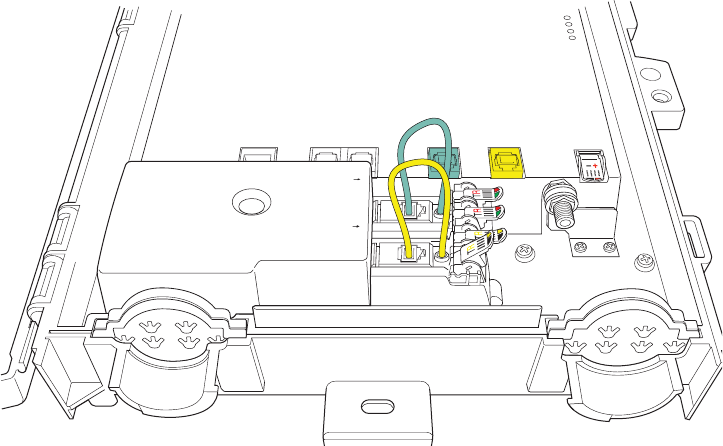
56 Chapter 6 Troubleshooting
Bypassing i3822V electronics
To isolate issues that are unrelated to the i3822V, you can rewire to remove the
i3822V from service, completely bypassing all electronics on the board, while
troubleshooting other problems in the home wiring.
To remove the i3822V from service:
1. Remove the connector from both DSL line 1 (grey) and DSL Line 2 (black) ports.
2. Remove the connector from both phone ports (grey and black) on the IDC.
3. Remove the connector from the Line 1 (green) port, and insert it into the grey
phone port on the IDC.
4. Remove the connector from the Line 2 (yellow) port, and insert it into the black
phone port on the IDC.
DSL LINE 2DSL LINE 1
FROM CO
LINE 1
LINE 2
COAX
ETHERNET
TELCO ACCESS
CO LINE 2
CO LINE 1
TO TEST VOICE SERVICE PLUG IN WORKING PHONE
POWER
Appendix A Regulatory Information 57
Regulatory Information A
Electrical
AC adapter
The i38HG and 4181N models are intended to be powered by a listed 2Wire or Pace
Direct Plug-In AC/DC Power adapter marked Class 2 or LPS and rated 5.1VDC, 2A.
The AC/DC Power adapter supplied with this product is designed to ensure your
personal safety and to be compatible with this equipment. Please follow these
guidelines:
•Do not use the adapter in a high moisture environment. Never touch the adapter
when your hands or feet are wet.
•Allow adequate ventilation around the adapter. Avoid locations with restricted
airflow.
•Connect the adapter to a proper power source. The voltage and grounding
requirements are found on the product case and/or packaging.
•Do not use the adapter if the cord becomes damaged.
•Do not attempt to service the adapter. There are no serviceable parts inside.
Replace the unit if it is damaged or exposed to excess moisture.
Telecommunication cord
CAUTION: To reduce the risk of fire, use only No. 26 AWG or larger UL Listed or CSA
Certified Telecommunication Line Cord.
Internal telephone ports (VoIP)
Telecommunication equipment connected to this port (for example, via "Voice 1 & 2"
port) should be UL Listed and the connections shall be made in accordance with
Article 800 of the NEC.
Location – electrical considerations
CAUTION: To reduce the risk of electrical shock or damage, do not use this product
near water, including a bathtub, wash bowl, kitchen sink or laundry tub, in a wet
basement, or near a swimming pool. Also, avoid using this product during electrical
storms. Avoid locations near electrical appliances or other devices that cause
58 Appendix A Regulatory Information
excessive voltage fluctuations or emit electrical noise (for example, air conditioners,
neon signs, high-frequency or magnetic security devices, or electric motors).
Equipment
Repairs
Do not, under any circumstances, attempt any service, adjustments, or repairs on this
equipment. Instead, contact your local Pace distributor or service provider for
assistance. Failure to comply may void the product warranty.
Location – environmental considerations
Do not plug the AC/DC power adapter into an outdoor outlet or operate the residential
gateway outdoors. It is not waterproof or dustproof, and is for indoor use only. Any
damage to the unit from exposure to rain or dust may void your warranty.
Do not use the residential gateway where there is high heat, dust, humidity, moisture,
or caustic chemicals or oils. Keep the gateway away from direct sunlight and anything
that radiates heat, such as a stove or a motor.
Do not place the gateway in enclosed areas having restricted airflow, such as,
electrical cabinet, closet, or entertainment center. Allow adequate ventilation around
the gateway for maximum air flow and cooling.
Declaration of conformity
Trade Name. Pace Americas
Responsible Party. 2Wire, Inc. DBA Pace America
Address. 1704 Automation Parkway, San Jose, CA 95131
Phone. (408) 428-9500
FCC / Industry Canada compliance
This device has been tested and certified as compliant with the regulations and
guidelines set forth in the Federal Communication commission - FCC part 15, FCC
part 68 and Industry Canada - ICES003 and RSS-210 Radio and telecommunication
regulatory requirements.
Le présent materiel est conforme aux specifications techniques applicables d'Industrie
Canada. Cet appareil numérique de la classe [*] est conforme à la norme NMB-003 du
Canada.
Manufacturer: 2Wire, Inc. DBA Pace Americas
Models: i3822V, iPSU, iPSU2, i38HG, 4181N
Appendix A Regulatory Information 59
Part 15 of FCC rules / IC RSS-210
This device complies with part 15 of the FCC Rules and Industry Canada license-
exempt RSS standard(s). Operation is subject to the following two conditions:
1. This device may not cause harmful interference, and
2. This device must accept any interference received, including interference that may
cause undesired operation of the device.
Le présent appareil est conforme aux normes CNR d'Industrie Canada applicables
aux appareils radio exempts de licence. L'exploitation est autorisée aux deux
conditions suivantes:
1. L'appareil ne doit pas produire de brouillage, et
2. L'utilisateur de l'appareil doit accepter tout brouillage radioélectrique subi, même
si le brouillage est susceptible d'en compromettre le fonctionnement.
This equipment has been tested and found to comply with the limits for a Class B
digital device, pursuant to part 15 of the FCC Rules. These limits are designed to
provide reasonable protection against harmful interference in a residential installation.
This equipment generates uses and can radiate radio frequency energy and, if not
installed and used in accordance with the instructions, may cause harmful
interference to radio communications. However, there is no guarantee that
interference will not occur in a particular installation. If this equipment does cause
harmful interference to radio or television reception, which can be determined by
turning the equipment off and on, the user is encouraged to try to correct the
interference by one or more of the following measures:
•Reorient or relocate the receiving antenna.
•Increase the separation between the equipment and receiver.
•Connect the equipment into an outlet on a circuit different from that to which the
receiver is connected.
•Consult the dealer or an experienced radio/TV technician for help.
CAUTION: Changes or modifications not expressly approved by the party responsible
for compliance could void your authority to operate this equipment.
TIA 968 (Part 68 of FCC rules) / IC CS-03
This equipment complies with the Telecommunication Industry Association TIA-968
(FCC part 68) and Industry Canada CS-03 Telecommunication requirements. On the
product is a label that contains, among other information, the IC and FCC registration
number and ringer equivalence number (REN) for this equipment. If requested, this
information may be provided to the telephone company.
The REN is used to determine the quantity of devices that may be connected to the
telephone line. Excessive RENs on the telephone line may result in the device not
ringing in response to an incoming call. In most, but not all areas, the sum of the
RENs should not exceed five (5.0).

60 Appendix A Regulatory Information
L'indice d'équivalence de la sonnerie (IES) sert à indiquer le nombre maximal de
terminaux qui peuvent être raccordés à une interface téléphonique. La terminaison
d'une interface peut consister en une combinaison quelconque de dispositifs, à la
seule condition que la somme d'indices d'équivalence de la sonnerie de tous les
dispositifs n'excède pas 5.
To be certain of the number of devices that may be connected to the line, as
determined by the total RENs, contact the telephone company to determine the
maximum RENs for the calling area.
This product cannot be used on telephone-company-provided coin service.
Connection to Party Line Service is subject to state tariffs.
An FCC-compliant telephone cord and modular plug is provided with this equipment.
This equipment is designed to be connected to the telephone network or premises
wiring using a compatible modular jack that is Part 68 compliant. If this equipment
causes harm to the telephone network, the telephone company will notify you in
advance that temporary discontinuance of service may be required. If advance notice
is not practical, the telephone company will notify the customer as soon as possible.
Also, you will be advised of your right to file a complaint with the FCC if you believe it
is necessary. The telephone company may make changes in its facilities, equipment,
operations, or procedures that could affect the operation of this equipment. If this
happens, the telephone company will provide advance notice in order for you to make
the necessary modifications to maintain uninterrupted service. If trouble is
experienced with this equipment, please contact Pace Americas, or your local Pace
Americas distributor or service center in the U.S.A. for repair and/or warrant
information. If the trouble is causing harm to the telephone network, the telephone
company may request you to remove this equipment from the network until the
problem is resolved. No repairs can be done by a customer on this equipment. It is
recommended that the customer install an AC surge arrestor in the AC outlet to which
this device is connected. This is to avoid damage to the equipment caused by local
lightning strikes and other electrical surges.
MPE/SAR/RF exposure information
This device was verified for RF exposure and found to comply with Council
Recommendation 1999/519/EC and FCC OET-65 RF exposure requirements. This
equipment complies with FCC radiation exposure limits set forth for an uncontrolled
environment.
WARNING: While this device is in operation, a separation distance of at least 20 cm
(8 inches) must be maintained between the radiating antenna inside the EUT and the
bodies of all persons exposed to the transmitter in order to meet the FCC RF
exposure guidelines. Making changes to the antenna or the device is not permitted.
Doing so may result in the installed system exceeding RF exposure requirements.
This device must not be co-located or operated in conjunction with any other antenna
or radio transmitter.
Appendix B Technical Specifications 61
Technical Specifications B
The i3822V outside unit operates under extreme weather conditions: driving rain,
snow, and sleet. The following table lists the specifications for the outside as well as
the power supply and inside units. Refer to the battery manufacturer’s documentation
for its specifications.
Physical specifications
i3822V (outside unit)
•13.0 in. x 12.0 in. x 5.0 in. (33.0 cm x 30.5 cm x 12.7 cm)
•6.4 lb. (2.9 kg)
iPSU (power supply unit)
•6.75 in. x 7.5 in. x 4.5 in. (17.1 cm x 19.1 cm x 11.4 cm)
•2 lb. without battery; 11 lb. with battery (0.9 kg without battery; 5.0 kg with battery)
i38HG (inside unit)
•8.25 in. x 7.4 in. x 1.3 in. (21 cm x 18.8 cm x 3.4 cm)
•1.1 lb. (.49 kg)
Operating environment
i3822V (outside unit)
•Temperature: –40º to 115º F (–40º to 46º C) + Solar Loading
•Humidity: 5% to 95% non-condensing
•Altitude: 0 to 13,000 feet (0 to 3,962 meters) mean sea level

62 Appendix B Technical Specifications
iPSU (power supply unit)
•Temperature: 41o to 122o F (5o C to 50o C)
•Humidity: 5% to 95% non-condensing
•Altitude: 0 to 13,000 feet (0 to 3,962 meters) mean sea level
i38HG (inside unit)
•Temperature: 32o to 104o F (0o C to 40o C)
•Humidity: 5% to 95% non-condensing
•Altitude: 0 to 13,000 feet (0 to 3,962 meters) mean sea level
Safety requirements
WARNING: This equipment contains integrated primary protection. This equipment is
not suitable for installation in CO and network locations that contain other primary
protection for OSP cable, such as EEEs (e.g., CEVs, and huts). The equipment may
be located in EECs where appropriate installation practices are used. (For example,
installation should not employ a separate primary protector for the equipment,
appropriate cabling should be run to the equipment, etc.)
WARNING: For the purposes of determining placement and location of fuse links or
fuse cable, the equipment shall be treated as a fuseless protector, regardless of any
capability to provide fusing.
WARNING: The intra-building ports of the equipment or subassembly is suitable for
connection to intrabuilding or unexposed wiring or cabling only. The intra-building
port(s) of the equipment or subassembly MUST NOT be metallically connected to
interfaces which connect to the OSP or its wiring. These interfaces are designed for
use as intra-building interfaces only (Type 2 or Type 4 ports as described in GR-1089-
CORE, Issue 4) and require isolation from the exposed OSP cabling. The addition of
Primary Protectors is not sufficient protection in order to connect these interfaces
metallically to OSP wiring.
Index 63
Index
A
AC power outage 23
B
backup battery
connecting 33
battery alert 36
battery backup 23
replacing 35
battery cable connector 35
BATTERY indicator 36
broadband operation
checking 52
C
COAX connector 20
cover
removing 13
D
drop wire 16
DSL link
status 52
DSL links
checking 49
E
encryption key
locating 45
I
i3822
ETHERNET port 31
LEDs
BATTERY 31
COAX 31
DATA 30
ETHERNET 31
LINE 1 31
POWER 30
VDSL 1 30
VDSL 2 30
i3822V 6
attaching the cover 22
bypassing 56
COAX connector 20
connecting insulation-displacement
connectors 20
connecting network cables 15
connecting power supply wires 17
connecting the coaxial cable 19
LED indicators 30
mounting 12
mounting template 13
POWER connector 18
powering up 29
i3822V ports
checking 51
DSL LINE 1 51
DSL LINE 2 51
ETHERNET 51
LINE 1 51
LINE 2 51
TELCO ACCESS 51
i3822V wiring
checking 50
i38HG 9, 40
avoiding signal interference 41
connecting the data cable 42
connecting the power adapter 43
connecting through wireless 44
connecting to a computer 43
DATA port 42
ETHERNET port 43
installation items 41
LED indicators 45
LEDs
BROADBAND 46
ETHERNET 45
LINE 1 46
LINE 2 46
NID 46
64 Index
POWER 45
SERVICE 46
WIRELESS 46
POWER indicator 43
replacing 46
inside unit
i38HG 9
intelligent Power Supply Unit (iPSU) 23
iPSU 8, 23
buttons
RESET 32
SILENCE ALARM 32
connecting power cables 27
disabling the battery alert 37
enabling the battery alert 37
install template 26
installation site 24
insulation-displacement connector
(IDC) 18
LED indicators 32
LEDs
BATTERY 32
POWER 32
mounting 25
POWER indicator 28
power terminal cover 27
replacing 37
N
network name
changing 47
O
outside unit
i3822V 6
P
phone jack 21
POWER connector 18
Power Supply Unit (iPSU) 8
S
SSID 44
locating 44
subscriber area 7
T
Telco access area 8
Telco access cover 15
testing cables 53
tools 10
V
VDSL cable connection 8
VDSL lines 17
video service
troubleshooting 54
voice services
troubleshooting 55
W
warning 12, 15, 60, 62
wireless adapters 44
wireless key
changing 47