ARRIS 3347 802.11b/g ADSL Router User Manual Software User Guide V7 7
ARRIS Group, Inc. 802.11b/g ADSL Router Software User Guide V7 7
ARRIS >
Abridged user manual

3
Table of Contents
Table of Contents
Copyright . . . . . . . . . . . . . . . . . . . . . . . . . . . . . . . . . . . . . . . . . . 2
CHAPTER 1
Introduction
. . . . . . . . . . . . . . . . . . . . . . . . . . . . . . . . . 13
What’s New in 7.7 . . . . . . . . . . . . . . . . . . . . . . . . . . . . . . . . . . 13
About Netopia Documentation . . . . . . . . . . . . . . . . . . . . . . . . . 15
Intended Audience . . . . . . . . . . . . . . . . . . . . . . . . . . . . . . . . . . 15
Documentation Conventions . . . . . . . . . . . . . . . . . . . . . . . . . . 16
General . . . . . . . . . . . . . . . . . . . . . . . . . . . . . . . . . . . . . . . . . . . . . . . . 16
Internal Web Interface . . . . . . . . . . . . . . . . . . . . . . . . . . . . . . . . . . . . . 16
Command Line Interface . . . . . . . . . . . . . . . . . . . . . . . . . . . . . . . . . . . 16
Organization . . . . . . . . . . . . . . . . . . . . . . . . . . . . . . . . . . . . . . . 18
A Word About Example Screens . . . . . . . . . . . . . . . . . . . . . . . 18
CHAPTER 2
Basic Mode Setup
. . . . . . . . . . . . . . . . . . . . . . . . . . . . . 19
Important Safety Instructions . . . . . . . . . . . . . . . . . . . . . . . . . . 20
POWER SUPPLY INSTALLATION . . . . . . . . . . . . . . . . . . . . . . . . . . . 20
TELECOMMUNICATION INSTALLATION. . . . . . . . . . . . . . . . . . . . . . 20
PRODUCT VENTILATION . . . . . . . . . . . . . . . . . . . . . . . . . . . . . . . . . 20
Wichtige Sicherheitshinweise . . . . . . . . . . . . . . . . . . . . . . . . . . 21
NETZTEIL INSTALLIEREN . . . . . . . . . . . . . . . . . . . . . . . . . . . . . . . . . 21
INSTALLATION DER TELEKOMMUNIKATION . . . . . . . . . . . . . . . . . 21
Setting up the Netopia Gateway . . . . . . . . . . . . . . . . . . . . . . . . 22
Microsoft Windows: . . . . . . . . . . . . . . . . . . . . . . . . . . . . . . . . . . . 22
Macintosh MacOS 8 or higher or Mac OS X: . . . . . . . . . . . . . . . 23
Configuring the Netopia Gateway . . . . . . . . . . . . . . . . . . . . . . 25
MiAVo VDSL and Ethernet WAN models Quickstart . . . . . . . . . . . . . . 26
PPPoE Quickstart . . . . . . . . . . . . . . . . . . . . . . . . . . . . . . . . . . . . . . . . 27
Set up the Netopia Pocket Gateway . . . . . . . . . . . . . . . . . . . . . . . . . . 29
Netopia Gateway Status Indicator Lights . . . . . . . . . . . . . . . . . 31

Table of Contents
4
Home Page - Basic Mode . . . . . . . . . . . . . . . . . . . . . . . . . . . . . 32
Manage My Account. . . . . . . . . . . . . . . . . . . . . . . . . . . . . . . . . . . . . . . 34
Status Details . . . . . . . . . . . . . . . . . . . . . . . . . . . . . . . . . . . . . . . . . . . . 35
Enable Remote Management. . . . . . . . . . . . . . . . . . . . . . . . . . . . . . . . 36
Expert Mode . . . . . . . . . . . . . . . . . . . . . . . . . . . . . . . . . . . . . . . . . . . . . 37
Update Firmware . . . . . . . . . . . . . . . . . . . . . . . . . . . . . . . . . . . . . . . . . 38
Factory Reset . . . . . . . . . . . . . . . . . . . . . . . . . . . . . . . . . . . . . . . . . . . . 39
CHAPTER 3
Expert Mode
. . . . . . . . . . . . . . . . . . . . . . . . . . . . . . . . . . 41
Accessing the Expert Web Interface . . . . . . . . . . . . . . . . . . . . . 41
Open the Web Connection . . . . . . . . . . . . . . . . . . . . . . . . . . . . . . . . . . 41
Home Page - Expert Mode . . . . . . . . . . . . . . . . . . . . . . . . . . . . . . . . . . 43
Home Page - Information . . . . . . . . . . . . . . . . . . . . . . . . . . . . . . . . . . . 43
Toolbar . . . . . . . . . . . . . . . . . . . . . . . . . . . . . . . . . . . . . . . . . . . 45
Navigating the Web Interface . . . . . . . . . . . . . . . . . . . . . . . . . . 45
Breadcrumb Trail . . . . . . . . . . . . . . . . . . . . . . . . . . . . . . . . . . . . . . . . . 45
Restart . . . . . . . . . . . . . . . . . . . . . . . . . . . . . . . . . . . . . . . . . . . 46
Alert Symbol . . . . . . . . . . . . . . . . . . . . . . . . . . . . . . . . . . . . . . . . . . . . . 47
Help . . . . . . . . . . . . . . . . . . . . . . . . . . . . . . . . . . . . . . . . . . . . . 48
Configure . . . . . . . . . . . . . . . . . . . . . . . . . . . . . . . . . . . . . . . . . 49
Quickstart . . . . . . . . . . . . . . . . . . . . . . . . . . . . . . . . . . . . . . . . . . . . . . . 49
How to Use the Quickstart Page . . . . . . . . . . . . . . . . . . . . . . . . . 49
Setup Your Gateway using a PPP Connection . . . . . . . . . . . . . . 49
LAN. . . . . . . . . . . . . . . . . . . . . . . . . . . . . . . . . . . . . . . . . . . . . . . . . . . . 51
Wireless . . . . . . . . . . . . . . . . . . . . . . . . . . . . . . . . . . . . . . . . . . . . . . . . 56
Privacy . . . . . . . . . . . . . . . . . . . . . . . . . . . . . . . . . . . . . . . . . . . . . . . . . 57
Advanced . . . . . . . . . . . . . . . . . . . . . . . . . . . . . . . . . . . . . . . . . . . . . . . 60
About Closed System Mode . . . . . . . . . . . . . . . . . . . . . . . . . . . . 62
WPA Version Allowed . . . . . . . . . . . . . . . . . . . . . . . . . . . . . . . . . 64
Multiple SSIDs . . . . . . . . . . . . . . . . . . . . . . . . . . . . . . . . . . . . . . . . . . . 65
WiFi Multimedia . . . . . . . . . . . . . . . . . . . . . . . . . . . . . . . . . . . . . . . . . . 67
Wireless MAC Authorization . . . . . . . . . . . . . . . . . . . . . . . . . . . . . . . . . 69
Use RADIUS Server . . . . . . . . . . . . . . . . . . . . . . . . . . . . . . . . . . 71
WAN . . . . . . . . . . . . . . . . . . . . . . . . . . . . . . . . . . . . . . . . . . . . . . . . . . . 73
PPP over Ethernet interface . . . . . . . . . . . . . . . . . . . . . . . . . . . . . . . . . 73
Advanced: . . . . . . . . . . . . . . . . . . . . . . . . . . . . . . . . . . . . . . . . . . 76
Ethernet WAN interface . . . . . . . . . . . . . . . . . . . . . . . . . . . . . . . . . . . . 78
WAN Ethernet and VDSL Gateways . . . . . . . . . . . . . . . . . . . . . . 81
ADSL Gateways . . . . . . . . . . . . . . . . . . . . . . . . . . . . . . . . . . . . . 82
Advanced . . . . . . . . . . . . . . . . . . . . . . . . . . . . . . . . . . . . . . . . . . . . . . . 87

5
Table of Contents
IP Static Routes. . . . . . . . . . . . . . . . . . . . . . . . . . . . . . . . . . . . . . . . . . 88
IP Static ARP. . . . . . . . . . . . . . . . . . . . . . . . . . . . . . . . . . . . . . . . . . . . 90
Pinholes. . . . . . . . . . . . . . . . . . . . . . . . . . . . . . . . . . . . . . . . . . . . . . . . 90
Configure Specific Pinholes . . . . . . . . . . . . . . . . . . . . . . . . . . . . 90
Planning for Your Pinholes . . . . . . . . . . . . . . . . . . . . . . . . . . . . . 90
Example: A LAN Requiring Three Pinholes . . . . . . . . . . . . . . . . 91
Pinhole Configuration Procedure . . . . . . . . . . . . . . . . . . . . . . . . 93
IPMaps . . . . . . . . . . . . . . . . . . . . . . . . . . . . . . . . . . . . . . . . . . . . . . . . 96
Configure the IPMaps Feature . . . . . . . . . . . . . . . . . . . . . . . . . . . . . . 97
FAQs for the IPMaps Feature . . . . . . . . . . . . . . . . . . . . . . . . . . . 97
What are IPMaps and how are they used? . . . . . . . . . . . . . . . . . 97
What types of servers are supported by IPMaps? . . . . . . . . . . . 97
Can I use IPMaps with my PPPoE or PPPoA connection? . . . . . 97
Will IPMaps allow IP addresses from different subnets to be assigned to my
Gateway? . . . . . . . . . . . . . . . . . . . . . . . . . . . . . . . . . . . . . . . . . . 97
IPMaps Block Diagram. . . . . . . . . . . . . . . . . . . . . . . . . . . . . . . . . 98
Default Server . . . . . . . . . . . . . . . . . . . . . . . . . . . . . . . . . . . . . . . . . . . 99
Configure a Default Server . . . . . . . . . . . . . . . . . . . . . . . . . . . . . 99
Typical Network Diagram . . . . . . . . . . . . . . . . . . . . . . . . . . . . . 100
NAT Combination Application . . . . . . . . . . . . . . . . . . . . . . . . . . 101
IP-Passthrough . . . . . . . . . . . . . . . . . . . . . . . . . . . . . . . . . . . . . 101
A restriction . . . . . . . . . . . . . . . . . . . . . . . . . . . . . . . . . . . . . . . . 102
Differentiated Services . . . . . . . . . . . . . . . . . . . . . . . . . . . . . . . . . . . 103
DNS. . . . . . . . . . . . . . . . . . . . . . . . . . . . . . . . . . . . . . . . . . . . . . . . . . 106
DHCP Server. . . . . . . . . . . . . . . . . . . . . . . . . . . . . . . . . . . . . . . . . . . 106
RADIUS Server . . . . . . . . . . . . . . . . . . . . . . . . . . . . . . . . . . . . . . . . . 108
SNMP . . . . . . . . . . . . . . . . . . . . . . . . . . . . . . . . . . . . . . . . . . . . . . . . 109
IGMP (Internet Group Management Protocol) . . . . . . . . . . . . . . . . . 112
UPnP . . . . . . . . . . . . . . . . . . . . . . . . . . . . . . . . . . . . . . . . . . . . . . . . . 115
LAN Management . . . . . . . . . . . . . . . . . . . . . . . . . . . . . . . . . . . . . . . 116
Ethernet Bridge . . . . . . . . . . . . . . . . . . . . . . . . . . . . . . . . . . . . . . . . . 117
Configuring for Bridge Mode . . . . . . . . . . . . . . . . . . . . . . . . . . . . . . . .118
VLAN . . . . . . . . . . . . . . . . . . . . . . . . . . . . . . . . . . . . . . . . . . . . . . . . . 121
Example #1 . . . . . . . . . . . . . . . . . . . . . . . . . . . . . . . . . . . . . . . . 129
Example #2 . . . . . . . . . . . . . . . . . . . . . . . . . . . . . . . . . . . . . . . . 132
System. . . . . . . . . . . . . . . . . . . . . . . . . . . . . . . . . . . . . . . . . . . . . . . . 135
Syslog Parameters . . . . . . . . . . . . . . . . . . . . . . . . . . . . . . . . . . . . . . 135
Log Event Messages. . . . . . . . . . . . . . . . . . . . . . . . . . . . . . . . . . . . . 137
Internal Servers . . . . . . . . . . . . . . . . . . . . . . . . . . . . . . . . . . . . . . . . . 140
Software Hosting . . . . . . . . . . . . . . . . . . . . . . . . . . . . . . . . . . . . . . . . 141
List of Supported Games and Software . . . . . . . . . . . . . . . . . . . 142
Rename a User(PC) . . . . . . . . . . . . . . . . . . . . . . . . . . . . . . . . . . . . . 143
Ethernet MAC Override . . . . . . . . . . . . . . . . . . . . . . . . . . . . . . . . . . . 144
Clear Options. . . . . . . . . . . . . . . . . . . . . . . . . . . . . . . . . . . . . . . . . . . 145

Table of Contents
6
Time Zone. . . . . . . . . . . . . . . . . . . . . . . . . . . . . . . . . . . . . . . . . . . . . . 145
Security . . . . . . . . . . . . . . . . . . . . . . . . . . . . . . . . . . . . . . . . . . 146
Passwords . . . . . . . . . . . . . . . . . . . . . . . . . . . . . . . . . . . . . . . . . . . . . 147
Create and Change Passwords . . . . . . . . . . . . . . . . . . . . . . . . . 147
Firewall . . . . . . . . . . . . . . . . . . . . . . . . . . . . . . . . . . . . . . . . . . . . . . . . 149
Use a Netopia Firewall . . . . . . . . . . . . . . . . . . . . . . . . . . . . . . . 149
BreakWater Basic Firewall . . . . . . . . . . . . . . . . . . . . . . . . . . . . . 149
Configuring for a BreakWater Setting . . . . . . . . . . . . . . . . . . . . 149
TIPS for making your BreakWater Basic Firewall Selection . . . 151
Basic Firewall Background . . . . . . . . . . . . . . . . . . . . . . . . . . . . 151
IPSec . . . . . . . . . . . . . . . . . . . . . . . . . . . . . . . . . . . . . . . . . . . . . . . . . 154
SafeHarbour IPSec VPN . . . . . . . . . . . . . . . . . . . . . . . . . . . . . . . . . . 155
Configuring a SafeHarbour VPN . . . . . . . . . . . . . . . . . . . . . . . . 156
Parameter Descriptions. . . . . . . . . . . . . . . . . . . . . . . . . . . . . . . 160
Stateful Inspection . . . . . . . . . . . . . . . . . . . . . . . . . . . . . . . . . . . . . . . 164
Stateful Inspection Firewall installation procedure . . . . . . . . . . . . . . . 164
Exposed Addresses . . . . . . . . . . . . . . . . . . . . . . . . . . . . . . . . . . . . . . 165
Stateful Inspection Options. . . . . . . . . . . . . . . . . . . . . . . . . . . . . . . . . 168
Open Ports in Default Stateful Inspection Installation . . . . . . . . . . . . 169
Firewall Tutorial . . . . . . . . . . . . . . . . . . . . . . . . . . . . . . . . . . . . 170
General firewall terms. . . . . . . . . . . . . . . . . . . . . . . . . . . . . . . . . . . . . 170
Basic IP packet components . . . . . . . . . . . . . . . . . . . . . . . . . . . . . . . 170
Basic protocol types . . . . . . . . . . . . . . . . . . . . . . . . . . . . . . . . . . . . . . 171
Firewall design rules. . . . . . . . . . . . . . . . . . . . . . . . . . . . . . . . . . . . . . 172
Firewall Logic. . . . . . . . . . . . . . . . . . . . . . . . . . . . . . . . . . . . . . . 172
Implied rules . . . . . . . . . . . . . . . . . . . . . . . . . . . . . . . . . . . . . . . 173
Example filter set page . . . . . . . . . . . . . . . . . . . . . . . . . . . . . . . 174
Filter basics. . . . . . . . . . . . . . . . . . . . . . . . . . . . . . . . . . . . . . . . . . . . . 175
Example network. . . . . . . . . . . . . . . . . . . . . . . . . . . . . . . . . . . . 175
Example filters . . . . . . . . . . . . . . . . . . . . . . . . . . . . . . . . . . . . . . . . . . 176
Example 1 . . . . . . . . . . . . . . . . . . . . . . . . . . . . . . . . . . . . . . . . . 176
Example 2 . . . . . . . . . . . . . . . . . . . . . . . . . . . . . . . . . . . . . . . . . 176
Example 3 . . . . . . . . . . . . . . . . . . . . . . . . . . . . . . . . . . . . . . . . . 176
Example 4 . . . . . . . . . . . . . . . . . . . . . . . . . . . . . . . . . . . . . . . . . 177
Example 5 . . . . . . . . . . . . . . . . . . . . . . . . . . . . . . . . . . . . . . . . . 177
Packet Filter . . . . . . . . . . . . . . . . . . . . . . . . . . . . . . . . . . . . . . . . . . . . 178
What’s a filter and what’s a filter set? . . . . . . . . . . . . . . . . . . . . . . . . . 179
How filter sets work. . . . . . . . . . . . . . . . . . . . . . . . . . . . . . . . . . . . . . . 179
Filter priority. . . . . . . . . . . . . . . . . . . . . . . . . . . . . . . . . . . . . . . . 180
How individual filters work . . . . . . . . . . . . . . . . . . . . . . . . . . . . . . . . . 180
A filtering rule. . . . . . . . . . . . . . . . . . . . . . . . . . . . . . . . . . . . . . . 181
Parts of a filter . . . . . . . . . . . . . . . . . . . . . . . . . . . . . . . . . . . . . . 181
Port numbers. . . . . . . . . . . . . . . . . . . . . . . . . . . . . . . . . . . . . . . 182

7
Table of Contents
Port number comparisons . . . . . . . . . . . . . . . . . . . . . . . . . . . . . 182
Other filter attributes. . . . . . . . . . . . . . . . . . . . . . . . . . . . . . . . . . 183
Putting the parts together. . . . . . . . . . . . . . . . . . . . . . . . . . . . . . 183
Filtering example #1. . . . . . . . . . . . . . . . . . . . . . . . . . . . . . . . . . 184
Filtering example #2. . . . . . . . . . . . . . . . . . . . . . . . . . . . . . . . . . 186
Design guidelines . . . . . . . . . . . . . . . . . . . . . . . . . . . . . . . . . . . . . . . 187
An approach to using filters . . . . . . . . . . . . . . . . . . . . . . . . . . . . 187
Working with IP Filters and Filter Sets . . . . . . . . . . . . . . . . . . 188
Adding a filter set. . . . . . . . . . . . . . . . . . . . . . . . . . . . . . . . . . . . . . . . 188
Adding filters to a filter set . . . . . . . . . . . . . . . . . . . . . . . . . . . . . . . . . 189
Viewing filters . . . . . . . . . . . . . . . . . . . . . . . . . . . . . . . . . . . . . . . 193
Modifying filters . . . . . . . . . . . . . . . . . . . . . . . . . . . . . . . . . . . . . 194
Deleting filters. . . . . . . . . . . . . . . . . . . . . . . . . . . . . . . . . . . . . . . 194
Moving filters . . . . . . . . . . . . . . . . . . . . . . . . . . . . . . . . . . . . . . . 194
Deleting a filter set. . . . . . . . . . . . . . . . . . . . . . . . . . . . . . . . . . . . . . . 194
Associating a Filter Set with an Interface . . . . . . . . . . . . . . . . 194
Policy-based Routing using Filtersets . . . . . . . . . . . . . . . . . . 197
TOS field matching . . . . . . . . . . . . . . . . . . . . . . . . . . . . . . . . . . . . . . 197
Security Log. . . . . . . . . . . . . . . . . . . . . . . . . . . . . . . . . . . . . . . . . . . . 200
Using the Security Monitoring Log . . . . . . . . . . . . . . . . . . . . . . . 200
Timestamp Background . . . . . . . . . . . . . . . . . . . . . . . . . . . . . . . 202
Install . . . . . . . . . . . . . . . . . . . . . . . . . . . . . . . . . . . . . . . . . . . 203
Install Software . . . . . . . . . . . . . . . . . . . . . . . . . . . . . . . . . . . . . . . . . 204
Updating Your Gateway’s Netopia Firmware Version . . . . . . . . 204
Step 1: Required Files. . . . . . . . . . . . . . . . . . . . . . . . . . . . . . . . . . . . 205
Step 2: Netopia firmware Image File . . . . . . . . . . . . . . . . . . . . . . . . . 205
Install Key . . . . . . . . . . . . . . . . . . . . . . . . . . . . . . . . . . . . . . . . . . . . . 209
Use Netopia Software Feature Keys . . . . . . . . . . . . . . . . . . . . . . . . . 209
Obtaining Software Feature Keys . . . . . . . . . . . . . . . . . . . . . . . 209
Procedure - Install a New Feature Key File . . . . . . . . . . . . . . . . 209
To check your installed features: . . . . . . . . . . . . . . . . . . . . . . . . 211
Install Certificate . . . . . . . . . . . . . . . . . . . . . . . . . . . . . . . . . . . . . . . . 213
CHAPTER 4
Basic Troubleshooting
. . . . . . . . . . . . . . . . . . . . . . . . 215
Status Indicator Lights . . . . . . . . . . . . . . . . . . . . . . . . . . . . . . 216
LED Function Summary Matrix . . . . . . . . . . . . . . . . . . . . . . . . . . . . . 225
Factory Reset Switch . . . . . . . . . . . . . . . . . . . . . . . . . . . . . . . 228

Table of Contents
8
CHAPTER 5
Advanced Troubleshooting
. . . . . . . . . . . . . . . . . . . . . . 231
Home Page. . . . . . . . . . . . . . . . . . . . . . . . . . . . . . . . . . . . . . . . . . . . . 232
Expert Mode . . . . . . . . . . . . . . . . . . . . . . . . . . . . . . . . . . . . . . . . . . . . 234
System Status. . . . . . . . . . . . . . . . . . . . . . . . . . . . . . . . . . . . . . . . . . . 235
Ports: Ethernet . . . . . . . . . . . . . . . . . . . . . . . . . . . . . . . . . . . . . . . . . . 236
Ports: DSL . . . . . . . . . . . . . . . . . . . . . . . . . . . . . . . . . . . . . . . . . . . . . 237
IP: Interfaces. . . . . . . . . . . . . . . . . . . . . . . . . . . . . . . . . . . . . . . . . . . . 238
DSL: Circuit Configuration . . . . . . . . . . . . . . . . . . . . . . . . . . . . . . . . . 239
System Log: Entire . . . . . . . . . . . . . . . . . . . . . . . . . . . . . . . . . . . . . . . 240
Diagnostics . . . . . . . . . . . . . . . . . . . . . . . . . . . . . . . . . . . . . . . . . . . . . 241
Network Tools. . . . . . . . . . . . . . . . . . . . . . . . . . . . . . . . . . . . . . . . . . . 242
CHAPTER 6
Command Line Interface
. . . . . . . . . . . . . . . . . . . . . . . 247
Overview . . . . . . . . . . . . . . . . . . . . . . . . . . . . . . . . . . . . . . . . . 248
Starting and Ending a CLI Session . . . . . . . . . . . . . . . . . . . . . 250
Logging In. . . . . . . . . . . . . . . . . . . . . . . . . . . . . . . . . . . . . . . . . . . . . . 250
Ending a CLI Session . . . . . . . . . . . . . . . . . . . . . . . . . . . . . . . . . . . . . 251
Saving Settings. . . . . . . . . . . . . . . . . . . . . . . . . . . . . . . . . . . . . . . . . . 251
Using the CLI Help Facility . . . . . . . . . . . . . . . . . . . . . . . . . . . 251
About SHELL Commands . . . . . . . . . . . . . . . . . . . . . . . . . . . . 251
SHELL Prompt . . . . . . . . . . . . . . . . . . . . . . . . . . . . . . . . . . . . . . . . . . 251
SHELL Command Shortcuts. . . . . . . . . . . . . . . . . . . . . . . . . . . . . . . . 252
SHELL Commands . . . . . . . . . . . . . . . . . . . . . . . . . . . . . . . . . 252
Common Commands . . . . . . . . . . . . . . . . . . . . . . . . . . . . . . . . . . . . . 252
WAN Commands . . . . . . . . . . . . . . . . . . . . . . . . . . . . . . . . . . . . . . . . 263
About CONFIG Commands . . . . . . . . . . . . . . . . . . . . . . . . . . 265
CONFIG Mode Prompt . . . . . . . . . . . . . . . . . . . . . . . . . . . . . . . . . . . . 265
Navigating the CONFIG Hierarchy . . . . . . . . . . . . . . . . . . . . . . . . . . . 265
Entering Commands in CONFIG Mode . . . . . . . . . . . . . . . . . . . . . . . 266
Guidelines: CONFIG Commands . . . . . . . . . . . . . . . . . . . . . . . . . . . . 267
Displaying Current Gateway Settings. . . . . . . . . . . . . . . . . . . . . . . . . 267
Step Mode: A CLI Configuration Technique . . . . . . . . . . . . . . . . . . . . 267
Validating Your Configuration . . . . . . . . . . . . . . . . . . . . . . . . . . . . . . . 268
CONFIG Commands . . . . . . . . . . . . . . . . . . . . . . . . . . . . . . . 269
Remote ATA Configuration Commands . . . . . . . . . . . . . . . . . . . . . . . 269
DSL Commands . . . . . . . . . . . . . . . . . . . . . . . . . . . . . . . . . . . . . . . . . 272
ATM Settings . . . . . . . . . . . . . . . . . . . . . . . . . . . . . . . . . . . . . . . 272
Bridging Settings. . . . . . . . . . . . . . . . . . . . . . . . . . . . . . . . . . . . . . . . . 274

9
Table of Contents
Common Commands . . . . . . . . . . . . . . . . . . . . . . . . . . . . . . . . . 274
DHCP Settings . . . . . . . . . . . . . . . . . . . . . . . . . . . . . . . . . . . . . . . . . 275
Common Commands . . . . . . . . . . . . . . . . . . . . . . . . . . . . . . . . . 275
DHCP Option Filtering . . . . . . . . . . . . . . . . . . . . . . . . . . . . . . . . 277
Example . . . . . . . . . . . . . . . . . . . . . . . . . . . . . . . . . . . . . . . . . . . 278
DMT Settings. . . . . . . . . . . . . . . . . . . . . . . . . . . . . . . . . . . . . . . . . . . 279
DSL Commands. . . . . . . . . . . . . . . . . . . . . . . . . . . . . . . . . . . . . 279
Domain Name System Settings. . . . . . . . . . . . . . . . . . . . . . . . . . . . . 280
Common Commands . . . . . . . . . . . . . . . . . . . . . . . . . . . . . . . . . 280
Dynamic DNS Settings. . . . . . . . . . . . . . . . . . . . . . . . . . . . . . . . 280
IGMP Settings . . . . . . . . . . . . . . . . . . . . . . . . . . . . . . . . . . . . . . . . . . 281
IP Settings . . . . . . . . . . . . . . . . . . . . . . . . . . . . . . . . . . . . . . . . . . . . . 284
Common Settings. . . . . . . . . . . . . . . . . . . . . . . . . . . . . . . . . . . . 284
ARP Timeout Settings . . . . . . . . . . . . . . . . . . . . . . . . . . . . . . . . 284
DSL Settings . . . . . . . . . . . . . . . . . . . . . . . . . . . . . . . . . . . . . . . 284
Ethernet LAN Settings . . . . . . . . . . . . . . . . . . . . . . . . . . . . . . . . 287
Additional subnets . . . . . . . . . . . . . . . . . . . . . . . . . . . . . . . . . . . 288
Default IP Gateway Settings . . . . . . . . . . . . . . . . . . . . . . . . . . . 289
IP-over-PPP Settings . . . . . . . . . . . . . . . . . . . . . . . . . . . . . . . . 289
Static ARP Settings . . . . . . . . . . . . . . . . . . . . . . . . . . . . . . . . . . 293
IGMP Forwarding . . . . . . . . . . . . . . . . . . . . . . . . . . . . . . . . . . . . 293
IPsec Passthrough . . . . . . . . . . . . . . . . . . . . . . . . . . . . . . . . . . . 293
IP Prioritization . . . . . . . . . . . . . . . . . . . . . . . . . . . . . . . . . . . . . . 294
Differentiated Services (DiffServ). . . . . . . . . . . . . . . . . . . . . . . . 294
Packet Mapping Configuration . . . . . . . . . . . . . . . . . . . . . . . . . . 296
Queue Configuration . . . . . . . . . . . . . . . . . . . . . . . . . . . . . . . . . . . . . 298
Basic Queue. . . . . . . . . . . . . . . . . . . . . . . . . . . . . . . . . . . . . . . . 299
Weighted Fair Queue . . . . . . . . . . . . . . . . . . . . . . . . . . . . . . . . . 300
Priority Queue . . . . . . . . . . . . . . . . . . . . . . . . . . . . . . . . . . . . . . 301
Funnel Queue. . . . . . . . . . . . . . . . . . . . . . . . . . . . . . . . . . . . . . . 302
Interface Queue Assignment . . . . . . . . . . . . . . . . . . . . . . . . . . . 302
SIP Passthrough . . . . . . . . . . . . . . . . . . . . . . . . . . . . . . . . . . . . 303
Static Route Settings . . . . . . . . . . . . . . . . . . . . . . . . . . . . . . . . . 303
IPMaps Settings . . . . . . . . . . . . . . . . . . . . . . . . . . . . . . . . . . . . . . . . 305
Network Address Translation (NAT) Default Settings . . . . . . . . . . . . 305
Network Address Translation (NAT) Pinhole Settings . . . . . . . . . . . . 306
PPPoE /PPPoA Settings . . . . . . . . . . . . . . . . . . . . . . . . . . . . . . . . . . 307
Configuring Basic PPP Settings . . . . . . . . . . . . . . . . . . . . . . . . 307
Configuring Port Authentication . . . . . . . . . . . . . . . . . . . . . . . . 309
PPPoE with IPoE Settings. . . . . . . . . . . . . . . . . . . . . . . . . . . . . . . . . .311
Ethernet WAN platforms. . . . . . . . . . . . . . . . . . . . . . . . . . . . . . . 311
ADSL platforms . . . . . . . . . . . . . . . . . . . . . . . . . . . . . . . . . . . . . 312
Ethernet Port Settings . . . . . . . . . . . . . . . . . . . . . . . . . . . . . . . . . . . . 314
Command Line Interface Preference Settings . . . . . . . . . . . . . . . . . 314

Table of Contents
10
Port Renumbering Settings . . . . . . . . . . . . . . . . . . . . . . . . . . . . . . . . 315
Security Settings. . . . . . . . . . . . . . . . . . . . . . . . . . . . . . . . . . . . . . . . . 316
Firewall Settings (for BreakWater Firewall) . . . . . . . . . . . . . . . . 316
SafeHarbour IPSec Settings . . . . . . . . . . . . . . . . . . . . . . . . . . . 316
Internet Key Exchange (IKE) Settings. . . . . . . . . . . . . . . . . . . . 321
Stateful Inspection. . . . . . . . . . . . . . . . . . . . . . . . . . . . . . . . . . . 322
Example: . . . . . . . . . . . . . . . . . . . . . . . . . . . . . . . . . . . . . . . . . . 323
Packet Filtering Settings . . . . . . . . . . . . . . . . . . . . . . . . . . . . . . 324
Example: . . . . . . . . . . . . . . . . . . . . . . . . . . . . . . . . . . . . . . . . . . 327
SNMP Settings . . . . . . . . . . . . . . . . . . . . . . . . . . . . . . . . . . . . . . . . . . 328
SNMP Notify Type Settings. . . . . . . . . . . . . . . . . . . . . . . . . . . . 329
System Settings . . . . . . . . . . . . . . . . . . . . . . . . . . . . . . . . . . . . . . . . . 329
Syslog. . . . . . . . . . . . . . . . . . . . . . . . . . . . . . . . . . . . . . . . . . . . . . . . . 333
Default syslog installation procedure. . . . . . . . . . . . . . . . . . . . . 334
Wireless Settings (supported models) . . . . . . . . . . . . . . . . . . . . . . . . 336
Wireless Multi-media (WMM) Settings . . . . . . . . . . . . . . . . . . . 340
Wireless Privacy Settings . . . . . . . . . . . . . . . . . . . . . . . . . . . . . 343
Wireless MAC Address Authorization Settings . . . . . . . . . . . . . 345
RADIUS Server Settings . . . . . . . . . . . . . . . . . . . . . . . . . . . . . . 345
VLAN Settings . . . . . . . . . . . . . . . . . . . . . . . . . . . . . . . . . . . . . . 346
Example: . . . . . . . . . . . . . . . . . . . . . . . . . . . . . . . . . . . . . . . . . . 347
UPnP settings . . . . . . . . . . . . . . . . . . . . . . . . . . . . . . . . . . . . . . 348
DSL Forum settings. . . . . . . . . . . . . . . . . . . . . . . . . . . . . . . . . . 348
TR-064 . . . . . . . . . . . . . . . . . . . . . . . . . . . . . . . . . . . . . . . . . . . . 348
TR-069 . . . . . . . . . . . . . . . . . . . . . . . . . . . . . . . . . . . . . . . . . . . . 349
CHAPTER 7
Glossary
. . . . . . . . . . . . . . . . . . . . . . . . . . . . . . . . . 351
-----A----- . . . . . . . . . . . . . . . . . . . . . . . . . . . . . . . . . . . . . . . . . . 351
-----B----- . . . . . . . . . . . . . . . . . . . . . . . . . . . . . . . . . . . . . . . . . . 352
-----C----- . . . . . . . . . . . . . . . . . . . . . . . . . . . . . . . . . . . . . . . . . . 353
-----D----- . . . . . . . . . . . . . . . . . . . . . . . . . . . . . . . . . . . . . . . . . . 354
-----E----- . . . . . . . . . . . . . . . . . . . . . . . . . . . . . . . . . . . . . . . . . . 356
-----F----- . . . . . . . . . . . . . . . . . . . . . . . . . . . . . . . . . . . . . . . . . . 356
-----H----- . . . . . . . . . . . . . . . . . . . . . . . . . . . . . . . . . . . . . . . . . . 357
-----I----- . . . . . . . . . . . . . . . . . . . . . . . . . . . . . . . . . . . . . . . . . . . 358
-----K----- . . . . . . . . . . . . . . . . . . . . . . . . . . . . . . . . . . . . . . . . . . 359
-----L-----. . . . . . . . . . . . . . . . . . . . . . . . . . . . . . . . . . . . . . . . . . . 359
-----M----- . . . . . . . . . . . . . . . . . . . . . . . . . . . . . . . . . . . . . . . . . . 359
-----N----- . . . . . . . . . . . . . . . . . . . . . . . . . . . . . . . . . . . . . . . . . . 360
-----P----- . . . . . . . . . . . . . . . . . . . . . . . . . . . . . . . . . . . . . . . . . . 361
-----Q----- . . . . . . . . . . . . . . . . . . . . . . . . . . . . . . . . . . . . . . . . . . 362
-----R----- . . . . . . . . . . . . . . . . . . . . . . . . . . . . . . . . . . . . . . . . . . 362

11
Table of Contents
-----S----- . . . . . . . . . . . . . . . . . . . . . . . . . . . . . . . . . . . . . . . . . . . 363
-----T----- . . . . . . . . . . . . . . . . . . . . . . . . . . . . . . . . . . . . . . . . . . . 365
-----U-----. . . . . . . . . . . . . . . . . . . . . . . . . . . . . . . . . . . . . . . . . . . 365
-----V----- . . . . . . . . . . . . . . . . . . . . . . . . . . . . . . . . . . . . . . . . . . . 366
-----W----- . . . . . . . . . . . . . . . . . . . . . . . . . . . . . . . . . . . . . . . . . . 366
-----X----- . . . . . . . . . . . . . . . . . . . . . . . . . . . . . . . . . . . . . . . . . . . 367
CHAPTER 8
Technical Specifications and Safety Information
. . . . . 369
Description . . . . . . . . . . . . . . . . . . . . . . . . . . . . . . . . . . . . . . . 369
Dimensions: . . . . . . . . . . . . . . . . . . . . . . . . . . . . . . . . . . . . . . . . 369
Communications interfaces: . . . . . . . . . . . . . . . . . . . . . . . . . . . 369
Power requirements . . . . . . . . . . . . . . . . . . . . . . . . . . . . . . . . . . . . . 369
Environment . . . . . . . . . . . . . . . . . . . . . . . . . . . . . . . . . . . . . . . . . . . 369
Operating temperature: . . . . . . . . . . . . . . . . . . . . . . . . . . . . . . . 369
Storage temperature: . . . . . . . . . . . . . . . . . . . . . . . . . . . . . . . . 369
Relative storage humidity: . . . . . . . . . . . . . . . . . . . . . . . . . . . . . 370
Software and protocols . . . . . . . . . . . . . . . . . . . . . . . . . . . . . . . . . . . 370
Software media: . . . . . . . . . . . . . . . . . . . . . . . . . . . . . . . . . . . . 370
Routing: . . . . . . . . . . . . . . . . . . . . . . . . . . . . . . . . . . . . . . . . . . . 370
WAN support: . . . . . . . . . . . . . . . . . . . . . . . . . . . . . . . . . . . . . . 370
Security: . . . . . . . . . . . . . . . . . . . . . . . . . . . . . . . . . . . . . . . . . . 370
Management/configuration methods: . . . . . . . . . . . . . . . . . . . . 370
Diagnostics: . . . . . . . . . . . . . . . . . . . . . . . . . . . . . . . . . . . . . . . . 370
Agency approvals . . . . . . . . . . . . . . . . . . . . . . . . . . . . . . . . . . 371
North America . . . . . . . . . . . . . . . . . . . . . . . . . . . . . . . . . . . . . . 371
International . . . . . . . . . . . . . . . . . . . . . . . . . . . . . . . . . . . . . . . . 371
Regulatory notices. . . . . . . . . . . . . . . . . . . . . . . . . . . . . . . . . . . . . . . 371
European Community. . . . . . . . . . . . . . . . . . . . . . . . . . . . . . . . . 371
Manufacturer’s Declaration of Conformance . . . . . . . . . . . . . 372
United States . . . . . . . . . . . . . . . . . . . . . . . . . . . . . . . . . . . . . . . 372
Service requirements . . . . . . . . . . . . . . . . . . . . . . . . . . . . . . . . 372
Canada . . . . . . . . . . . . . . . . . . . . . . . . . . . . . . . . . . . . . . . . . . . 373
Declaration for Canadian users . . . . . . . . . . . . . . . . . . . . . . . . . 373
Caution. . . . . . . . . . . . . . . . . . . . . . . . . . . . . . . . . . . . . . . . . . . . 373
Important Safety Instructions . . . . . . . . . . . . . . . . . . . . . . . . . 374
Australian Safety Information . . . . . . . . . . . . . . . . . . . . . . . . . . . 374
Caution. . . . . . . . . . . . . . . . . . . . . . . . . . . . . . . . . . . . . . . . . . . . 374
Caution. . . . . . . . . . . . . . . . . . . . . . . . . . . . . . . . . . . . . . . . . . . . 374
Telecommunication installation cautions . . . . . . . . . . . . . . . . . . 374
47 CFR Part 68 Information . . . . . . . . . . . . . . . . . . . . . . . . . . 375
FCC Requirements . . . . . . . . . . . . . . . . . . . . . . . . . . . . . . . . . . . . . . 375

Table of Contents
12
FCC Statements . . . . . . . . . . . . . . . . . . . . . . . . . . . . . . . . . . . . . . . . . 375
Electrical Safety Advisory . . . . . . . . . . . . . . . . . . . . . . . . . . . . 376
CHAPTER 9
Overview of Major Capabilities
. . . . . . . . . . . . . . . . . . . 377
Wide Area Network Termination . . . . . . . . . . . . . . . . . . . . . . . 378
PPPoE/PPPoA (Point-to-Point Protocol over Ethernet/ATM) . . . . . . . 378
Instant-On PPP. . . . . . . . . . . . . . . . . . . . . . . . . . . . . . . . . . . . . . . . . . 378
Simplified Local Area Network Setup . . . . . . . . . . . . . . . . . . . 379
DHCP (Dynamic Host Configuration Protocol) Server . . . . . . . . . . . . 379
DNS Proxy . . . . . . . . . . . . . . . . . . . . . . . . . . . . . . . . . . . . . . . . . . . . . 379
Management . . . . . . . . . . . . . . . . . . . . . . . . . . . . . . . . . . . . . . 380
Embedded Web Server . . . . . . . . . . . . . . . . . . . . . . . . . . . . . . . . . . . 380
Diagnostics . . . . . . . . . . . . . . . . . . . . . . . . . . . . . . . . . . . . . . . . 380
Security . . . . . . . . . . . . . . . . . . . . . . . . . . . . . . . . . . . . . . . . . . 381
Remote Access Control . . . . . . . . . . . . . . . . . . . . . . . . . . . . . . . . . . . 381
Password Protection . . . . . . . . . . . . . . . . . . . . . . . . . . . . . . . . . 381
Network Address Translation (NAT) . . . . . . . . . . . . . . . . . . . . . 381
Netopia Advanced Features for NAT . . . . . . . . . . . . . . . . . . . . 383
Internal Servers . . . . . . . . . . . . . . . . . . . . . . . . . . . . . . . . . . . . . 383
Pinholes. . . . . . . . . . . . . . . . . . . . . . . . . . . . . . . . . . . . . . . . . . . 383
Default Server . . . . . . . . . . . . . . . . . . . . . . . . . . . . . . . . . . . . . . 384
Combination NAT Bypass Configuration. . . . . . . . . . . . . . . . . . 384
IP-Passthrough . . . . . . . . . . . . . . . . . . . . . . . . . . . . . . . . . . . . . 385
VPN IPSec Pass Through . . . . . . . . . . . . . . . . . . . . . . . . . . . . . 385
VPN IPSec Tunnel Termination. . . . . . . . . . . . . . . . . . . . . . . . . 386
Stateful Inspection Firewall . . . . . . . . . . . . . . . . . . . . . . . . . . . . 386
SSL Certificate Support. . . . . . . . . . . . . . . . . . . . . . . . . . . . . . . 386
VLANs . . . . . . . . . . . . . . . . . . . . . . . . . . . . . . . . . . . . . . . . . . . . 386
Index . . . . . . . . . . . . . . . . . . . . . . . . . . . . . . . . . . . . . . . . . . . . .389

13
What’s New in 7.7
CHAPTER 1 Introduction
What’s New in 7.7
New in Netopia Firmware Version 7.7 are the following features:
•
Internet Group Management Protocol (IGMP) Version 3 support.
See “IGMP (Internet Group Management Protocol)” on page 112.
•
TR-101 Support:
• Concurrent support for PPPoE and IPoE connections on the WAN.
See “WAN” on page 73.
• Multiple LAN IP Subnet support. See “LAN” on page 51.
• Additional DHCP range support. These ranges are associated with the additional
LAN subnets on a 1-to-1 basis.
• DHCP option filtering support. Allows DHCP option data to be used to determine the
desired DHCP address range. See “DHCP Option Filtering” on page 277.
• Support for additional WAN settings to control multicast forwarding as well as if
0.0.0.0
is used as the source address for IGMP packets.
See “Advanced:” on page 76.
• Support for “unnumbered” interfaces. For IP interfaces, this allows the address to be
set to
0
and the DHCP client also to be disabled. See page 79.
•
PPPoE/DHCP Autosensing. See “WAN” on page 73.
•
Wireless Multimedia Mode (WMM) support. See “WiFi Multimedia” on page 67.
•
Support of VLAN ID 0 on the Ethernet WAN and support for setting p-bits on a segment/
port basis. See “VLAN” on page 121 and CLI “VLAN Settings” on page 346.
•
Firewall: ClearSailing is automatically enabled on all 2200-Series ADSL2+ platforms.
(Explicit exceptions: bonded and VDSL2, 3341, and 3387WG.) See “Firewall” on
page 149.

14
•
TR-069 Remote device management is automatically enabled by default for 2200-
Series Gateways. (Explicit exceptions: bonded and VDSL2, 3341, 3387WG). See “TR-
069” on page 349.
Corresponding commands have been added to the Command Line Interface (CLI). See
“Command Line Interface” on page 247.
•
Reset WAN port counter and CLI command to display individual Ethernet port statistics.
See “reset enet [ all ]” on page 257 and “show enet [ all ]” on page 259.
•
CLI for Netopia ATA Remote Management.
See “Remote ATA Configuration Commands” on page 269.
•
Provide Bandwidth Management using Weighted Fair Queueing for VDSL2 Platforms.
See “Queue Configuration” on page 298.

15
About Netopia Documentation
About Netopia Documentation
☛
NOTE:
This guide describes the wide variety of features and functionality of the Neto-
pia Gateway, when used in Router mode. The Netopia Gateway may also be
delivered in Bridge mode. In Bridge mode, the Gateway acts as a pass-through
device and allows the workstations on your LAN to have public addresses
directly on the Internet.
Netopia, Inc. provides a suite of technical information for its 2200- and 3300-series family
of intelligent enterprise and consumer Gateways. It consists of:
•
Software User Guide
•
Dedicated Quickstart guides
•
Specific White Papers
The documents are available in electronic form as Portable Document Format (PDF) files.
They are viewed (and printed) from Adobe Acrobat Reader, Exchange, or any other applica-
tion that supports PDF files.
They are downloadable from Netopia’s website:
http://www.netopia.com/
Intended Audience
This guide is targeted primarily to residential service subscribers.
Expert Mode sections may also be of use to the support staffs of broadband service pro-
viders and advanced residential service subscribers.
See “Expert Mode” on page 41.

16
Documentation Conventions
General
This manual uses the following conventions to present information:
Internal Web Interface
Command Line Interface
Syntax conventions for the Netopia Gateway command line interface are as follows:
Convention (Typeface) Description
bold italic
monospaced
Menu commands
bold italic sans serif
Web GUI page links and button names
terminal Computer display text
bold terminal User-entered text
Italic Italic type indicates the complete titles of
manuals.
Convention (Graphics) Description
Denotes an “excerpt” from a Web page or
the visual truncation of a Web page
Denotes an area of emphasis on a Web
page
Convention Description
straight ([ ]) brackets in cmd line Optional command arguments
blue rectangle or line
solid rounded rectangle
with an arrow

17
Documentation Conventions
curly ({ }) brackets, with values sep-
arated with vertical bars (|).
Alternative values for an argument are pre-
sented in curly ({ }) brackets, with values
separated with vertical bars (|).
bold terminal type
face
User-entered text
italic terminal
type face
Variables for which you supply your own val-
ues

18
Organization
This guide consists of nine chapters, including a glossary, and an index. It is organized as
follows:
•Chapter 1, “Introduction” — Describes the Netopia document suite, the purpose of,
the audience for, and structure of this guide. It gives a table of conventions.
•Chapter 2, “Basic Mode Setup” — Describes how to get up and running with your
Netopia Gateway.
•Chapter 3, “Expert Mode” — Focuses on the “Expert Mode” Web-based user inter-
face for advanced users. It is organized in the same way as the Web UI is organized. As
you go through each section, functions and procedures are discussed in detail.
•Chapter 4, “Basic Troubleshooting” — Gives some simple suggestions for trouble-
shooting problems with your Gateway’s initial configuration.
•Chapter 5, “Advanced Troubleshooting” — Gives suggestions and descriptions of
expert tools to use to troubleshoot your Gateway’s configuration.
•Chapter 6, “Command Line Interface” — Describes all the current text-based com-
mands for both the SHELL and CONFIG modes. A summary table and individual com-
mand examples for each mode is provided.
•Chapter 7, “Glossary”
•Chapter 8, “Technical Specifications and Safety Information”
•Chapter 9, “Overview of Major Capabilities” — Presents a product description sum-
mary.
•Index
A Word About Example Screens
This manual contains many example screen illustrations. Since Netopia 2200- and 3300
Series Gateways offer a wide variety of features and functionality, the example screens
shown may not appear exactly the same for your particular Gateway or setup as they
appear in this manual. The example screens are for illustrative and explanatory purposes,
and should not be construed to represent your own unique environment.

369
Description
CHAPTER 8 Technical Specifications and
Safety Information
Description
Dimensions:
Smart Modems: 13.5 cm (w) x 13.5 cm (d) x 3.5 cm (h); 5.25” (w) x 5.25” (d) x 1.375” (h)
Wireless Models: 19.5 cm (w) x 17.0 cm (d) x 4.0 cm (h); 7.6” (w) x 6.75” (d) x 1.5” (h)
3342/3342N/3352/3352N: 8.5 cm (w) x 4.5 cm (d) x 2 cm (h); 3.375” (w) x 1.75” (d) x .875” (h)
2200-Series Modems: 1.06"(2.69 cm) H, 4.36" (11.07 cm) W, 5.71"(14.50 cm) L
2200-Series Wireless Models: 1.2"(3.0cm) H, 8.7" (22.0 cm) W, 5.2"(13.2cm) L
Communications interfaces: The Netopia Gateways have an RJ-11 jack for DSL line
connections or an RJ-45 jack for cable/DSL modem connections and 1 or 4–port 10/100Base-T
Ethernet switch for your LAN connections. Some models have a USB port that can be used to
connect to your PC; in some cases, the USB port also serves as the power source. Some models
contain an 802.11b or 802.11g wireless LAN transmitter.
Power requirements
■12 VDC input
■USB-powered models only: For Use with Listed I.T.E. Only
Environment
Operating temperature: 0° to +40° C
Storage temperature: 0° to +70° C

370
Relative storage humidity: 20 to 80% noncondensing
Software and protocols
Software media: Software preloaded on internal flash memory; field upgrades done via download
to internal flash memory via TFTP or web upload. (does not apply to 3342/3352)
Routing: TCP/IP Internet Protocol Suite, RIP
WAN support: PPPoA, PPPoE, DHCP, static IP address
Security: PAP, CHAP, UI password security, IPsec, SSL certificate
Management/configuration methods: HTTP (Web server), Telnet, SNMP, TR-069 DSL Forum
CPE WAN Management Protocol
Diagnostics: Ping, event logging, routing table displays, statistics counters, web-based
management, traceroute, nslookup, and diagnostic commands.

371
Agency approvals
Agency approvals
North America
Safety Approvals:
■United States – UL 60950, Third Edition
■Canada – CSA: CAN/CSA-C22.2 No. 60950-00
EMC:
■United States – FCC Part 15 Class B
■Canada – ICES-003
Telecom:
■United States – 47 CFR Part 68
■Canada – CS-03
International
Safety Approvals:
■Low Voltage (European directive) 73/23
■EN60950 (Europe)
EMI Compatibility:
■89/336/EEC (European directive)
■EN55022:1994 CISPR22 Class B
■EN300 386 V1.2.1 (non-wireless products)
■EN 301-489 (wireless products)
Regulatory notices
European Community. This Netopia product conforms to the European Community CE Mark
standard for the design and manufacturing of information technology equipment. This standard
covers a broad area of product design, including RF emissions and immunity from electrical
disturbances.

372
The Netopia Firmware Version 7.7 complies with the following EU directives:
■Low Voltage, 73/23/EEC
■EMC Compatibility, 89/336/EEC, conforming to EN 55 022
Manufacturer’s Declaration of Conformance
☛ Warnings:
This is a Class B product. In a domestic environment this product may cause radio
interference, in which case the user may be required to take adequate measures. Ade-
quate measures include increasing the physical distance between this product and
other electrical devices.
Changes or modifications to this unit not expressly approved by the party responsible
for compliance could void the user’s authority to operate the equipment.
United States. This equipment has been tested and found to comply with the limits for a Class B
digital device, pursuant to Part 15 of the FCC Rules. These limits are designed to provide reasonable
protection against harmful interference in a residential installation. This equipment generates, uses,
and can radiate radio frequency energy and, if not installed and used in accordance with the
instructions, may cause harmful inter ference to radio communications. However, there is no
guarantee that interference will not occur in a particular installation. If this equipment does cause
harmful interference to radio or television reception, which can be determined by turning the
equipment off and on, the user is encouraged to try to correct the interference by one or more of the
following measures:
■Reorient or relocate the receiving antenna.
■Increase the separation between the equipment and receiver.
■Connect the equipment into an outlet on a circuit different from that to which the receiver is
connected.
■Consult the dealer or an experienced radio TV technician for help.
Service requirements. In the event of equipment malfunction, all repairs should be performed by
our Company or an authorized agent. Under FCC rules, no customer is authorized to repair this
equipment. This restriction applies regardless of whether the equipment is in or our of warranty. It is
the responsibility of users requiring service to report the need for service to our Company or to one
of our authorized agents. Service can be obtained at Netopia, Inc., 6001 Shellmound Street,
Emeryville, California, 94608. Telephone: 510-597-5400.

373
Manufacturer’s Declaration of Conformance
☛ Important
This product was tested for FCC compliance under conditions that included the use of
shielded cables and connectors between system components. Changes or modifica-
tions to this product not authorized by the manufacturer could void your authority to
operate the equipment.
Canada. This Class B digital apparatus meets all requirements of the Canadian Interference -
Causing Equipment Regulations.
Cet appareil numérique de la classe B respecte toutes les exigences du Réglement sur le matériel
brouilleur du Canada.
Declaration for Canadian users
NOTICE: The Canadian Industry Canada label identifies certified equipment. This
certification means that the equipment meets certain telecommunications network
protective, operation, and safety requirements. The Department does not guarantee the
equipment will operate to the user’s satisfaction.
Before installing this equipment, users should ensure that it is permissible to be
connected to the facilities of the local telecommunications company. The equipment
must also be installed using an acceptable method of connection. In some cases, the
company’s inside wiring associated with a single line individual service may be extended
by means of a certified connector assembly (telephone extension cord). The customer
should be aware that compliance with the above conditions may not prevent degradation
of service in some situations.
Repairs to the certified equipment should be made by an authorized Canadian
maintenance facility designated by the supplier. Any repairs or alterations made by the
user to this equipment, or equipment malfunctions, may give the telecommunications
company cause to request the user to disconnect the equipment.
Users should ensure for their own protection that the electrical ground connections of
the power utility, telephone lines, and internal metallic water pipe system, if present, are
connected together. This precaution may be particularly important in rural areas.
Caution
Users should not attempt to make such connections themselves, but should contact the appropriate
electric inspection authority, or electrician, as appropriate.
The Ringer Equivalence Number (REN) assigned to each terminal device provides an indication of the
maximum number of terminals allowed to be connected to a telephone interface. The termination on
an interface may consist of any combination of devices subject only to the requirement that the sum
of the Ringer Equivalence Numbers of all the devices does not exceed 5.

374
Important Safety Instructions
Australian Safety Information
The following safety information is provided in conformance with Australian safety requirements:
Caution
DO NOT USE BEFORE READING THE INSTRUCTIONS: Do not connect the Ethernet ports to a carrier or
carriage service provider’s telecommunications network or facility unless: a) you have the written
consent of the network or facility manager, or b) the connection is in accordance with a connection
permit or connection rules.
Connection of the Ethernet ports may cause a hazard or damage to the telecommunication network
or facility, or persons, with consequential liability for substantial compensation.
Caution
■The direct plug-in power supply serves as the main power disconnect; locate the direct plug-in
power supply near the product for easy access.
■For use only with CSA Certified Class 2 power supply, rated 12VDC.
Telecommunication installation cautions
■Never install telephone wiring during a lightning storm.
■Never install telephone jacks in wet locations unless the jack is specifically designed for wet
locations.
■Never touch uninsulated telephone wires or terminals unless the telephone line has been
disconnected at the network interface.
■Use caution when installing or modifying telephone lines.
■Avoid using a telephone (other than a cordless type) during an electrical storm. There may be a
remote risk of electric shock from lightning.
■Do not use the telephone to report a gas leak in the vicinity of the leak.

375
47 CFR Part 68 Information
47 CFR Part 68 Information
FCC Requirements
1. The Federal Communications Commission (FCC) has established Rules which permit this device
to be directly connected to the telephone network. Standardized jacks are used for these
connections. This equipment should not be used on party lines or coin phones.
2. If this device is malfunctioning, it may also be causing harm to the telephone network; this
device should be disconnected until the source of the problem can be determined and until
repair has been made. If this is not done, the telephone company may temporarily disconnect
service.
3. The telephone company may make changes in its technical operations and procedures; if such
changes affect the compatibility or use of this device, the telephone company is required to give
adequate notice of the changes. You will be advised of your right to file a complaint with the
FCC.
4. If the telephone company requests information on what equipment is connected to their lines,
inform them of:
a. The telephone number to which this unit is connected.
b. The ringer equivalence number. [0.XB]
c. The USOC jack required. [RJ11C]
d. The FCC Registration Number. [XXXUSA-XXXXX-XX-E]
Items (b) and (d) are indicated on the label. The Ringer Equivalence Number (REN) is used to
determine how many devices can be connected to your telephone line. In most areas, the sum
of the REN's of all devices on any one line should not exceed five (5.0). If too many devices are
attached, they may not ring properly.
FCC Statements
a) This equipment complies with Part 68 of the FCC rules and the requirements adopted by the ACTA.
On the bottom of this equipment is a label that contains, among other information, a product
identifier in the format US:AAAEQ##TXXXX. If requested, this number must be provided to the
telephone company.
b) List all applicable certification jack Universal Service Order Codes (“USOC”) for the equipment:
RJ11.
c) A plug and jack used to connect this equipment to the premises wiring and telephone network
must comply with the applicable FCC Part 68 rules and requirements adopted by the ACTA. A
compliant telephone cord and modular plug is provided with this product. It is designed to be
connected to a compatible modular jack that is also compliant. See installation instructions for
details.

376
d) The REN is used to determine the number of devices that may be connected to a telephone line.
Excessive RENs on a telephone line may result in the devices not ringing in response to an incoming
call. In most but not all areas, the sum of RENs should not exceed five (5.0). To be certain of the
number of devices that may be connected to a line, as determined by the total RENs, contact the
local telephone company. For products approved after July 23, 2002, the REN for this product is part
of the product identifier that has the format US:AAAEQ##TXXXX. The digits represented by ## are the
REN without a decimal point (e.g., 03 is a REN of 0.3). For earlier products, the REN is separately
shown on the label.
e) If this equipment, the Netopia 3300- or 2200-Series router, causes harm to the telephone
network, the telephone company will notify you in advance that temporary discontinuance of service
may be required. But if advance notice isn’t practical, the telephone company will notify the customer
as soon as possible. Also, you will be advised of your right to file a complaint with the FCC if you
believe it is necessary.
f) The telephone company may make changes in its facilities, equipment, operations or procedures
that could affect the operation of the equipment. If this happens the telephone company will provide
advance notice in order for you to make necessary modifications to maintain uninterrupted service.
g) If trouble is experienced with this equipment, the Netopia 3300- or 2200-Series router, for repair
or warranty information, please contact:
Netopia Technical Support
510-597-5400
www.netopia.com.
If the equipment is causing harm to the telephone network, the telephone company may request that
you disconnect the equipment until the problem is resolved.
h) This equipment not intended to be repaired by the end user. In case of any problems, please refer
to the troubleshooting section of the Product User Manual before calling Netopia Technical Support.
i) Connection to party line service is subject to state tariffs. Contact the state public utility
commission, public service commission or corporation commission for information.
j) If your home has specially wired alarm equipment connected to the telephone line, ensure the
installation of this Netopia 3300- or 2200-Series router does not disable your alarm equipment. If
you have questions about what will disable alarm equipment, consult your telephone company or
qualified installer.
RF Exposure Statement:
NOTE: Installation of the wireless models must maintain at least 20 cm between the wireless
router and any body part of the user to be in compliance with FCC RF exposure guidelines.
Electrical Safety Advisory
Telephone companies report that electrical surges, typically lightning transients, are very destructive
to customer terminal equipment connected to AC power sources. This has been identified as a major
nationwide problem. Therefore it is advised that this equipment be connected to AC power through
the use of a surge arrestor or similar protection device.

377
CHAPTER 9 Overview of Major Capabilities
The Netopia Gateway offers simplified setup and management features as well as
advanced broadband router capabilities. The following are some of the main features of
the Netopia Gateway:
•“Wide Area Network Termination” on page 378
The Gateway combines an ADSL modem with an Internet router. It translates protocols
used on the Internet to protocols used by home personal computers and eliminates the
need for special desktop software (i.e. PPPoE).
•“Simplified Local Area Network Setup” on page 379
Built-in DHCP and DNS proxy features minimize or eliminate the need to program any
network configuration into your home personal computer.
•“Management” on page 380
A Web server built into the Netopia Operating System makes setup and maintenance
easy using standard browsers. Diagnostic tools facilitate troubleshooting.
•“Security” on page 381
Network Address Translation (NAT), password protection, Stateful Inspection firewall
and other built-in security features prevent unauthorized remote access to your network.
Pinholes, default server, and other features permit access to computers on your home
network that you can specify.

378
Wide Area Network Termination
PPPoE/PPPoA (Point-to-Point Protocol over Ethernet/ATM)
The PPPoE specification, incorporating the PPP and Ethernet standards, allows your com-
puter(s) to connect to your Service Provider’s network through your Ethernet WAN connec-
tion. The Netopia-series Gateway supports PPPoE, eliminating the need to install PPPoE
client software on any LAN computers.
Service Providers may require the use of PPP authentication protocols such as Challenge
Handshake Authentication Protocol (CHAP) or Password Authentication Protocol (PAP).
CHAP and PAP use a username and password pair to authenticate users with a PPP server.
A CHAP authentication process works as follows:
1. The password is used to scramble a challenge string.
2. The password is a shared secret, known by both peers.
3. The unit sends the scrambled challenge back to the peer.
PAP, a less robust method of authentication, sends a username and password to a PPP
server to be authenticated. PAP’s username and password pair are not encrypted, and are
therefore sent “unscrambled”.
Instant-On PPP
You can configure your Gateway for one of two types of Internet connections:
•Always On
•Instant On
These selections provide either an uninterrupted Internet connection or an as-needed con-
nection.
While an Always On connection is convenient, it does leave your network permanently con-
nected to the Internet, and therefore potentially vulnerable to attacks.
Netopia's Instant On technology furnishes almost all the benefits of an Always-On connec-
tion while providing two additional security benefits:
•Your network cannot be attacked when it is not connected.

379
Simplified Local Area Network Setup
•Your network may change address with each connection making it more difficult to
attack.
When you configure Instant On access, you can also configure an idle time-out value. Your
Gateway monitors traffic over the Internet link and when there has been no traffic for the
configured number of seconds, it disconnects the link.
When new traffic that is destined for the Internet arrives at the Gateway, the Gateway will
instantly re-establish the link.
Your service provider may be using a system that assigns the Internet address of your
Gateway out of a pool of many possible Internet addresses. The address assigned varies
with each connection attempt, which makes your network a moving target for any attacker.
Simplified Local Area Network Setup
DHCP (Dynamic Host Configuration Protocol) Server
DHCP Server functionality enables the Gateway to assign to your LAN computer(s) a “pri-
vate” IP address and other parameters that allow network communication. The default
DHCP Server configuration of the Gateway supports up to 253 LAN IP addresses.
This feature simplifies network administration because the Gateway maintains a list of IP
address assignments. Additional computers can be added to your LAN without the hassle
of configuring an IP address.
DNS Proxy
Domain Name System (DNS) provides end users with the ability to look for devices or web
sites by typing their names, rather than IP addresses. For web surfers, this technology
allows you to enter the URL (Universal Resource Locator) as text to surf to a desired web-
site.
The Netopia DNS Proxy feature allows the LAN-side IP address of the Gateway to be used
for proxying DNS requests from hosts on the LAN to the DNS Servers configured in the
gateway. This is accomplished by having the Gateway's LAN address handed out as the
“DNS Server” to the DHCP clients on the LAN.

380
☛ NOTE:
The Netopia DNS Proxy only proxies UDP DNS queries, not TCP DNS queries.
Management
Embedded Web Server
There is no specialized software to install on your PC to configure, manage, or maintain
your Netopia Gateway. Web pages embedded in the operating system provide access to
the following Gateway operations:
•Setup
•System and security logs
•Diagnostics functions
Once you have removed your Netopia Gateway from its packing container and powered the
unit up, use any LAN attached PC or workstation running a common web browser applica-
tion to configure and monitor the Gateway.
Diagnostics
In addition to the Gateway’s visual LED indicator lights, you can run an extensive set of
diagnostic tools from your Web browser.
Two of the facilities are:
•Automated “Multi-Layer” Test
The
Run Diagnostics
link initiates a sequence of tests. They examine the entire
functionality of the Gateway, from the physical connections to the data traffic.
•Network Test Tools
Three test tools to determine network reachability are available:
Ping - tests the “reachability” of a particular network destination by sending an ICMP
echo request and waiting for a reply.
NSLookup - converts a domain name to its IP address and vice versa.

381
Security
TraceRoute - displays the path to a destination by showing the number of hops and the
router addresses of these hops.
The system log also provides diagnostic information.
☛ NOTE:
Your Service Provider may request information that you acquire from these var-
ious diagnostic tools. Individual tests may be performed at the command line.
(See “Command Line Interface” on page 247.).
Security
Remote Access Control
You can determine whether or not an administrator or other authorized person has access
to configuring your Gateway. This access can be turned on or off in the Web interface.
Password Protection
Access to your Netopia device can be controlled through two access control accounts,
Admin or User.
•The Admin, or administrative user, performs all configuration, management or mainte-
nance operations on the Gateway.
•The User account provides monitor capability only.
A user may NOT change the configuration, perform upgrades or invoke maintenance
functions.
Account usernames can now be changed for the Admin and User accounts.
Network Address Translation (NAT)
The Netopia Gateway Network Address Translation (NAT) security feature lets you conceal
the topology of a hard-wired Ethernet or wireless network connected to its LAN inter face
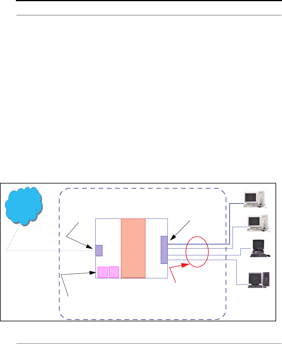
382
from routers on networks connected to its WAN interface. In other words, the end com-
puter stations on your LAN are invisible from the Internet.
Only a single WAN IP address is required to provide this security support for your entire
LAN.
LAN sites that communicate through an Internet Service Provider typically enable NAT,
since they usually purchase only one IP address from the ISP.
•When NAT is ON, the Netopia Gateway “proxies” for the end computer stations on your
network by pretending to be the originating host for network communications from non-
originating networks. The WAN interface address is the only IP address exposed.
The Netopia Gateway tracks which local hosts are communicating with which remote
hosts. It routes packets received from remote networks to the correct computer on the
LAN (Ethernet) inter face.
•When NAT is OFF, a Netopia Gateway acts as a traditional TCP/IP router, all LAN com-
puters/devices are exposed to the Internet.
A diagram of a typical NAT-enabled LAN follows:
WAN
Interface
LAN
Ethernet
Interface
Netopia Gateway
NAT
Internet
Embedded Admin Services:
HTTP-Web Server and Telnet Server Port
NAT-protected
LAN stations
Ethernet

383
Security
☛ NOTE:
1. The default setting for NAT is ON.
2. Netopia uses Port Address Translation (PAT) to implement the NAT facility.
3. NAT Pinhole traffic (discussed below) is always initiated from the WAN side.
Netopia Advanced Features for NAT
Using the NAT facility provides effective LAN security. However, there are user applications
that require methods to selectively by-pass this security function for certain types of Inter-
net traffic.
Netopia Gateways provide special pinhole configuration rules that enable users to estab-
lish NAT-protected LAN layouts that still provide flexible by-pass capabilities.
Some of these rules require coordination with the unit’s embedded administration ser-
vices: the internal Web (HTTP) Port (TCP 80) and the internal Telnet Server Port (TCP 23).
Internal Servers
The internal servers are the embedded Web and Telnet servers of the Gateway. You would
change the internal server ports for Web and Telnet of the Gateway if you wanted to have
these services on the LAN using pinholes or the Default server.
Pinholes
This feature allows you to:
•Transparently route selected types of network traffic using the port forwarding facility.
FTP requests or HTTP (Web) connections are directed to a specific host on your LAN.
•Setup multiple pinhole paths.
Up to 32 paths are supported
•Identify the type(s) of traffic you want to redirect by port number.

384
Common TCP/IP protocols and ports are:
See page 90 for How To instructions.
Default Server
This feature allows you to:
•Direct your Gateway to forward all externally initiated IP traffic (TCP and UDP protocols
only) to a default host on the LAN.
•Enable it for certain situations:
Where you cannot anticipate what port number or packet protocol an in-bound applica-
tion might use.
For example, some network games select arbitrary port numbers when a connection is
opened.
When you want all unsolicited traffic to go to a specific LAN host.
Combination NAT Bypass Configuration
Specific pinholes and Default Server settings, each directed to different LAN devices, can
be used together.
☛ WARNING:
Creating a pinhole or enabling a Default Server allows inbound access to the
specified LAN station. Contact your Network Administrator for LAN security
questions.
FTP (TCP 21) telnet (TCP 23)
SMTP (TCP 25) HTTP (TCP 80)
SNMP (TCP 161, UDP 161)
385
Security
IP-Passthrough
Netopia OS now offers an IP passthrough feature. The IP passthrough feature allows a sin-
gle PC on the LAN to have the Gateway’s public address assigned to it. It also provides PAT
(NAPT) via the same public IP address for all other hosts on the private LAN subnet.
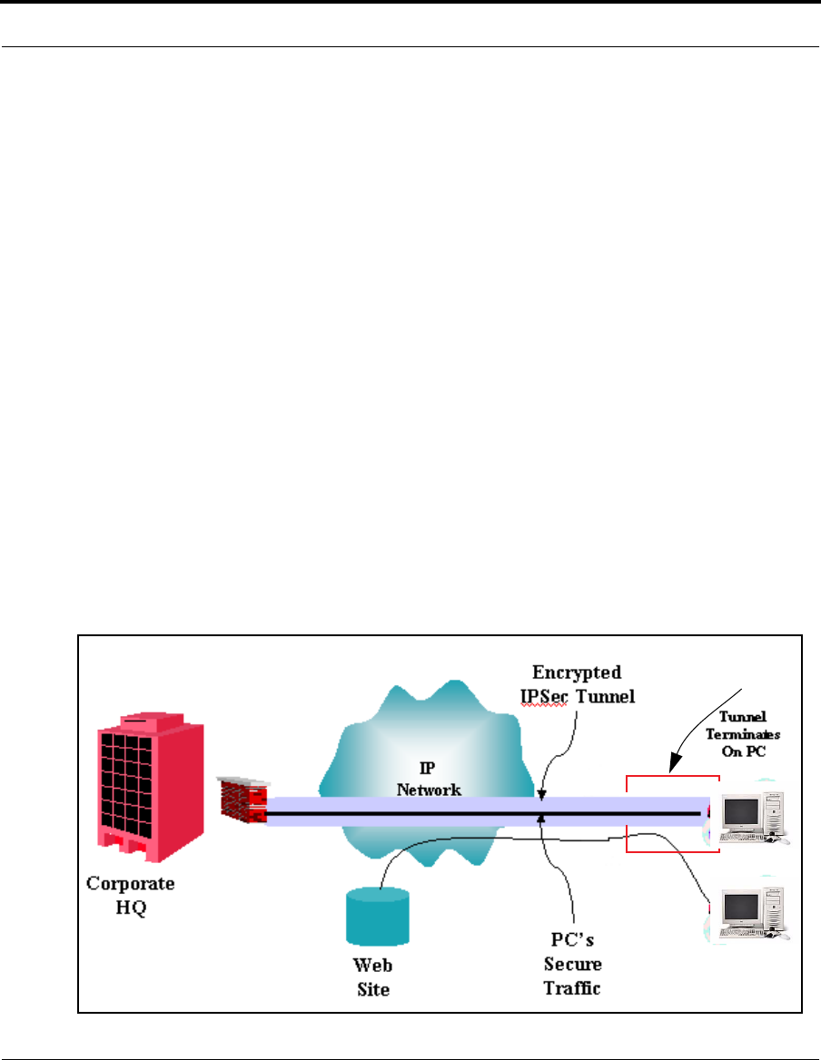
VPN IPSec Pass Through
This Netopia service supports your independent VPN client software in a transparent man-
ner. Netopia has implemented an Application Layer Gateway (ALG) to support multiple PCs
running IP Security protocols.
This feature has three elements:
1. On power up or reset, the address mapping function (NAT) of the Gate-
way’s WAN configuration is turned on by default.
2. When you use your third-party VPN application, the Gateway recognizes
the traffic from your client and your unit. It allows the packets to pass
through the NAT “protection layer” via the encrypted IPSec tunnel.
3. The encrypted IPSec tunnel is established “through” the Gateway.
A typical VPN IPSec Tunnel pass through is diagrammed below:
Netopia
Gateway

386
☛ NOTE:
Typically, no special configuration is necessary to use the IPSec pass through
feature.
In the diagram, VPN PC clients are shown behind the Netopia Gateway and the
secure server is at Corporate Headquarters across the WAN. You cannot have
your secure server behind the Netopia Gateway.
When multiple PCs are starting IPSec sessions, they must be started one at a
time to allow the associations to be created and mapped.
VPN IPSec Tunnel Termination
This Netopia service supports termination of VPN IPsec tunnels at the Gateway. This per-
mits tunnelling from the Gateway without the use of third-party VPN client software on your
client PCs.
Stateful Inspection Firewall
Stateful inspection is a security feature that prevents unsolicited inbound access when
NAT is disabled. You can configure UDP and TCP “no-activity” periods that will also apply to
NAT time-outs if stateful inspection is enabled on the interface.
Technical details are discussed in “Expert Mode” on page 41.
SSL Certificate Support
On selected models, you can also install a Secure Sockets Layer (SSL V3.0) certificate
from a trusted Certification Authority (CA) for authentication purposes. If this feature is
available on your Gateway, an additional link will appear in the Install page.
Netopia Firmware Version 7.7 uses SSL certificates for TR-069 support.
See “Install Certificate” on page 213.
VLANs
Netopia's VGx technology allows a single Netopia VGx-enabled broadband gateway to act
as separate virtual gateways, treating each individual service as a single service "chan-
nel." The VGx-enabled gateway applies specific policies, routing, and prioritization parame-
ters to each service channel, ensuring delivery of that service to the appropriate peripheral

387
Security
device with the requisite level of QoS and correct feature sets — making it ideal for deliv-
ery of triple play voice, video, and data services.
VGx was developed to ensure that subscribers receive the quality of voice, video, and data
services they expect — to prevent a large data download from causing jittery video or poor
voice quality. VGx achieves this goal by providing superior service segmentation and QoS
features obtained by mapping multiple local virtual local area networks (VLANs) to one or
more specific permanent virtual circuits (PVCs) for DSL, or wide area network VLANs for a
fiber network.
Traffic prioritization is determined through the Institute of Electrical Engineering (IEEE)
standard 802.1p, which specifies QoS algorithms to prioritize traffic based on protocol and
source. This insures that each service receives the QoS treatment it requires; for example,
•video is free from latency,
•VoIP service is prioritized to insure aural quality, and
•data is securely and efficiently routed.

388

389
Index
Symbols
!! command 252
A
Access the GUI 41
Address resolution table 260
Administrative
restrictions 290
Administrator password 41,
147, 250
Arguments, CLI 266
ARP
Command 252, 263
ATA configuration 269
Authentication 309
Authentication trap 328
auto-channel mode 336
AutoChannel Setting 61, 336
B
Bridging 274
Broadcast address 284, 287
C
CLI 247
!! command 252
Arguments 266
Command shortcuts 252
Command truncation 265
Configuration mode 265
Keywords 266
Navigating 265
Prompt 251, 265
Restart command 252
SHELL mode 251
View command 267
Command
ARP 252, 263
Ping 255
Telnet 262
Command line interface (see
CLI)
Community 328
Compression, protocol 308
Concurrent Bridging/
Routing 119, 274
CONFIG
Command List 249
Configuration mode 265
D
D. port 184
Default IP address 41
denial of service 364
designing a new filter set 187
DHCP 275
DHCP filtering 277
DHCP lease table 257
Diagnostic log 257, 261
Level 330
Diagnostics 380
DNS 280
DNS Proxy 379
Documentation
conventions 16

390
Domain Name System
(DNS) 280
DSL Forum settings 348
E
Echo request 308
echo-period 308
Embedded Web Server 380
Ethernet address 274
Ethernet statistics 257
F
Feature Keys
Obtaining 209
filter
parts 181
parts of 181
filter priority 180
filter set
adding 188
display 183
filter sets
adding 188
defined 179
deleting 194
disadvantages 178
using 188
filtering example #1 184
filters
actions a filter can
take 180
adding to a filter set 190
defined 179
deleting 194
input 189
modifying 194
output 189
using 187, 188
viewing 193
firewall 261
FTP 305
H
Hardware address 274
hijacking 364
Hop count 304
HTTP traffic 315
I
ICMP Echo 255
IGMP Snooping 113, 281
Install 203
Install Certificate 213
IP address 284, 287
Default 41
IP interfaces 260
IP routes 261
IPMap table 261
IPSec Tunnel 260
K
Keywords, CLI 266
L
LAN Host Discovery
Table 261
latency 197

391
LCP echo request 308
Link
Install Software 203
Quickstart 49, 51, 73
Local Area Network 379
Location, SNMP 328
Log 261
Logging in 250
lost echoes 308
M
Magic number 308
Memory 261
Metric 304
multi-cast forwarding 285,
312
Multiple SSIDs 65
multiple subnets 53
Multiple Wireless SSIDs
Wireless 65, 337
N
Nameserver 280
NAT 291, 305, 381
Traffic rules 101
NAT Default Server 384
Netmask 287
Network Address
Translation 381
Network Test Tools 380
NSLookup 380
O
set upnp option 348
Operating Mode
Wireless 60, 337
P
PAP 378
Password 147
Administrator 41, 147,
250
User 41, 147, 250
persistent-log 330
Ping 380
Ping command 255
Pinholes 305, 383
Planning 90
policy-based routing 197
Port authentication 309
port number
comparisons 182
port numbers 182
Port renumbering 315
PPP 264
PPPoE 378
Primary nameserver 280
Prompt, CLI 251, 265
Protocol compression 308
Q
qos max-burst-size 273
qos peak-cell-rate 272
qos service-class 272
qos sustained-cell-rate 273
quality of service 181, 197

392
R
Restart 258
Restart command 252
Restart timer 309
Restrictions 290
RIP 286, 288
Routing Information Protocol
(RIP) 286, 288
S
Secondary nameserver 280
Secure Sockets Layer 213
Security
filters 178
Security log 201
Set bncp command 272,
273, 274
Set bridge commands 274
Set DMT commands 279
Set dns commands 280
Set ip static-routes
commands 303
Set ppp module port authenti-
cation command 310
Set preference more
command 314
Set preference verbose
command 314
set security state-insp 322
Set servers command 315
Set servers telnet-tcp
command 315
Set snmp sysgroup location
command 328
Set snmp traps authentifica-
tion-traps ip-address
command 328
Set system diagnostic-level
command 330
Set system heartbeat
command 331
Set system name
command 329
Set system NTP
command 332
Set system password
command 331
set system syslog 333
Set wireless option
command 336
Set wireless user-auth option
command 345
SHELL
Command Shortcuts 252
Commands 251
Prompt 251
SHELL level 265
SHELL mode 251
show config 258
Show ppp 264
Simple Network Management
Protocol (SNMP) 328
SMTP 305
SNMP 109, 305, 328
SNMP Notify Type
settings 329
src. port
184
SSL certificates 213

393
Stateful Inspection 164
stateful inspection 261
Static route 303
Step mode 267
Subnet mask 287
subnets
multiple 53
Syslog 135
System contact, SNMP 328
System diagnostics 330
system idle-timeout 330
T
Telnet 250, 305
Telnet command 262
Telnet traffic 315
TFTP 305
TFTP server 254
Toolbar 45
TOS bit 181, 197
TraceRoute 242, 381
Trap 328
Trivial File Transfer
Protocol 254
Truncation 265
U
UPnP 115
User name 250
User password 41, 147, 250
V
set atm 272, 273
View command 267
view config 263
VLAN ID 124
VLAN Settings 346
VLANs 121
VPN
IPSec Pass Through 385
IPSec Tunnel
Termination 386
W
Weighted Fair Queue 300
Wide Area Network 378
Wireless 56
Z
Zero Touch 332

394

Netopia 2200 and 3300 series by Netopia
Netopia, Inc.
6001 Shellmound Street
Emeryville, CA 94608
August 18, 2006