ARRIS 3387W Ethernet to Ethernet Router with 802.11b User Manual Software User Guide V7 2
ARRIS Group, Inc. Ethernet to Ethernet Router with 802.11b Software User Guide V7 2
UserManual.wiki
>
ARRIS
>
3387W User Manual
Users Guide
Navigation menu
Upload a User Manual
Namespaces
Wiki Guide
HTML
PDF
Info
Views
User Manual
Discussion / Help
Navigation
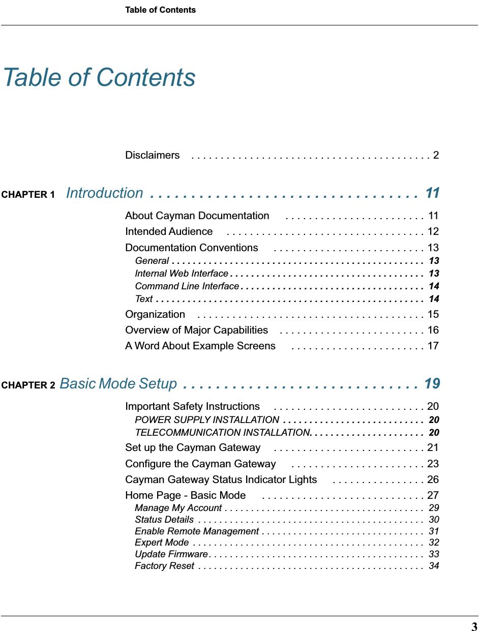
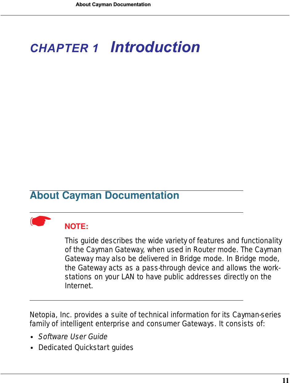
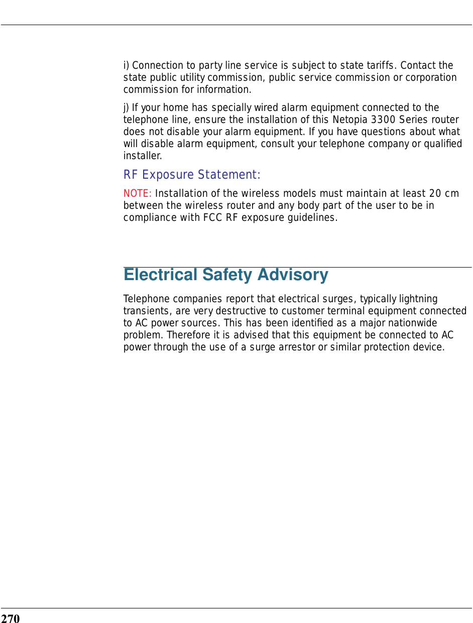
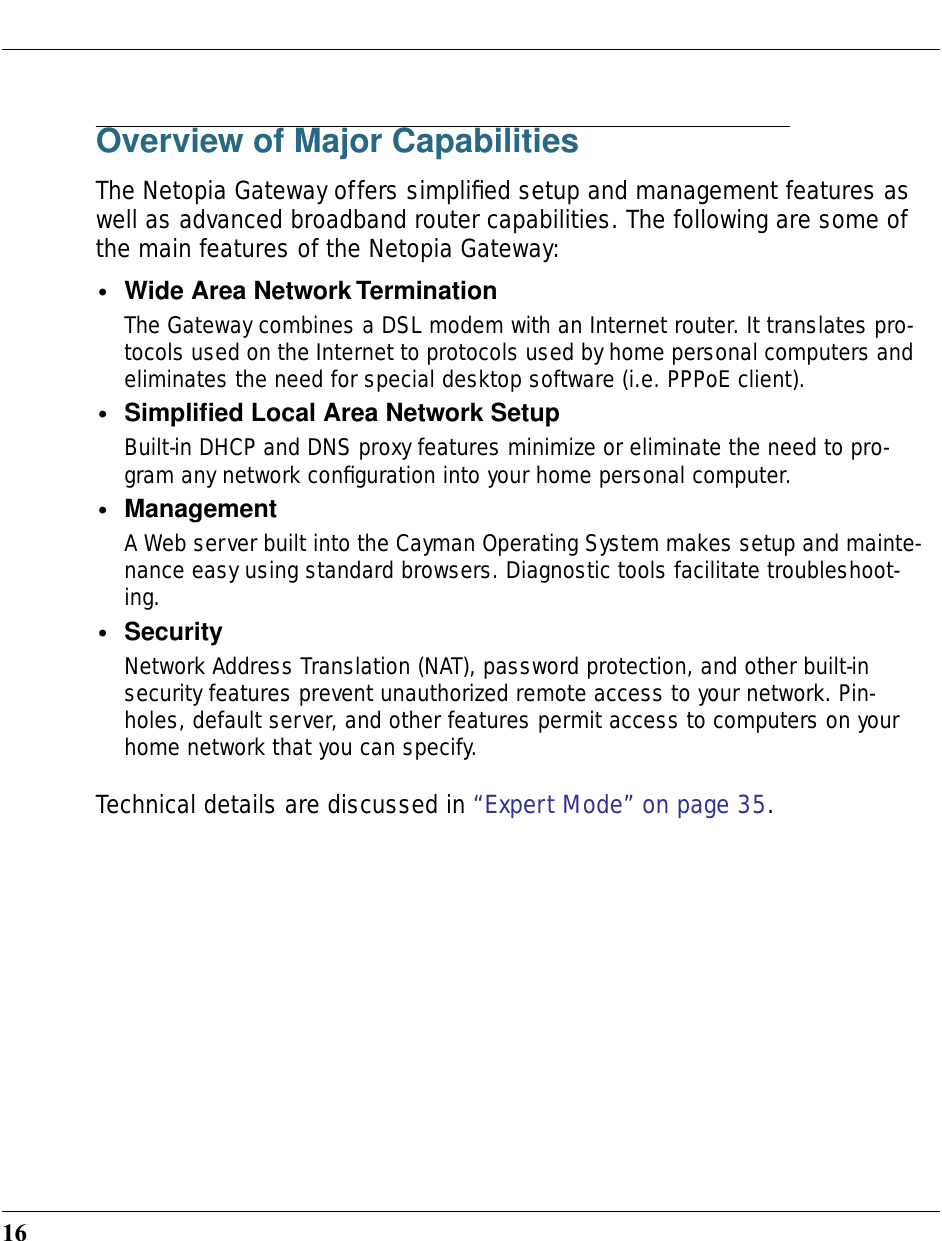
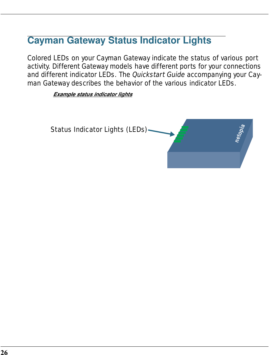
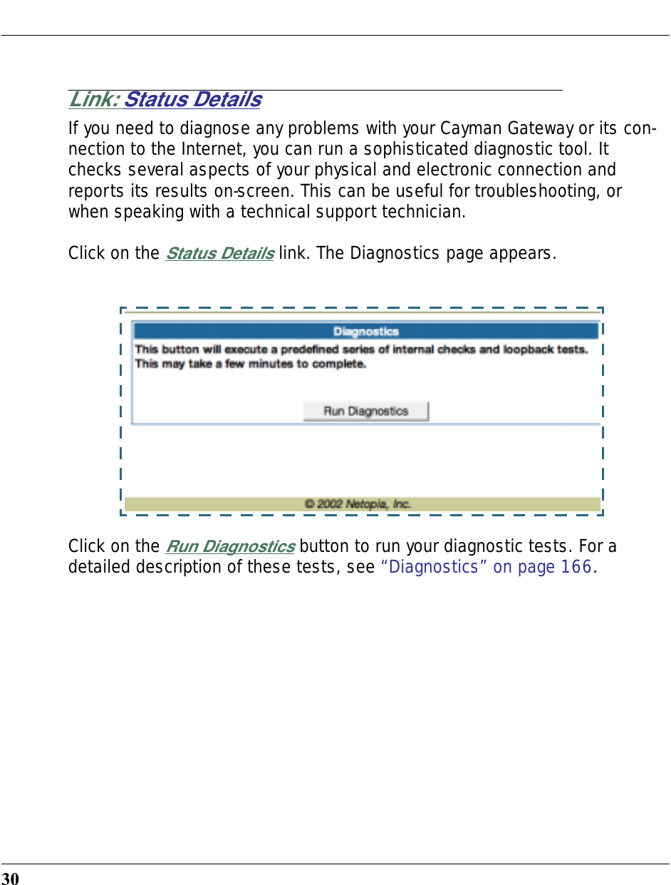
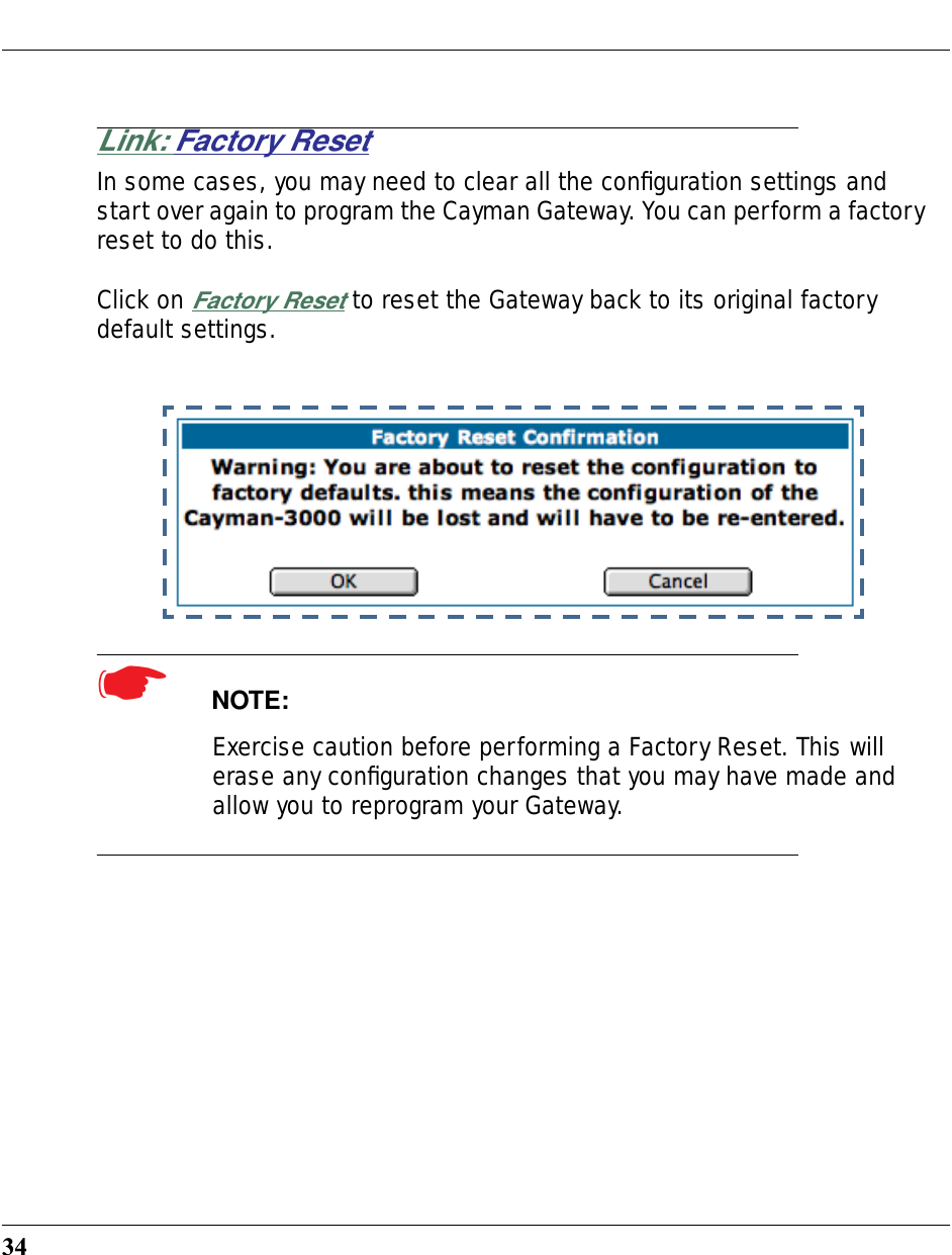
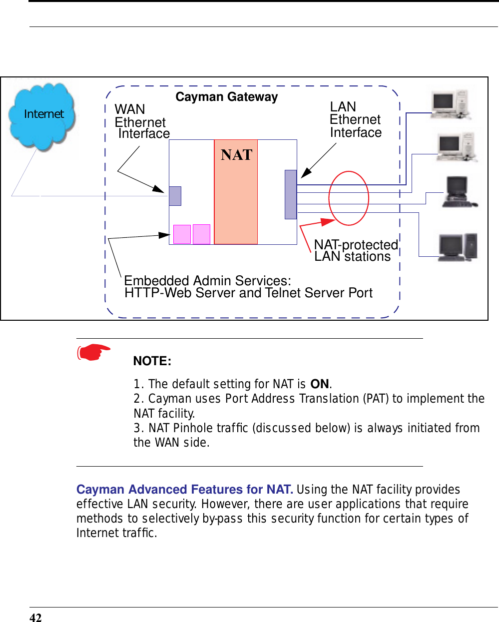
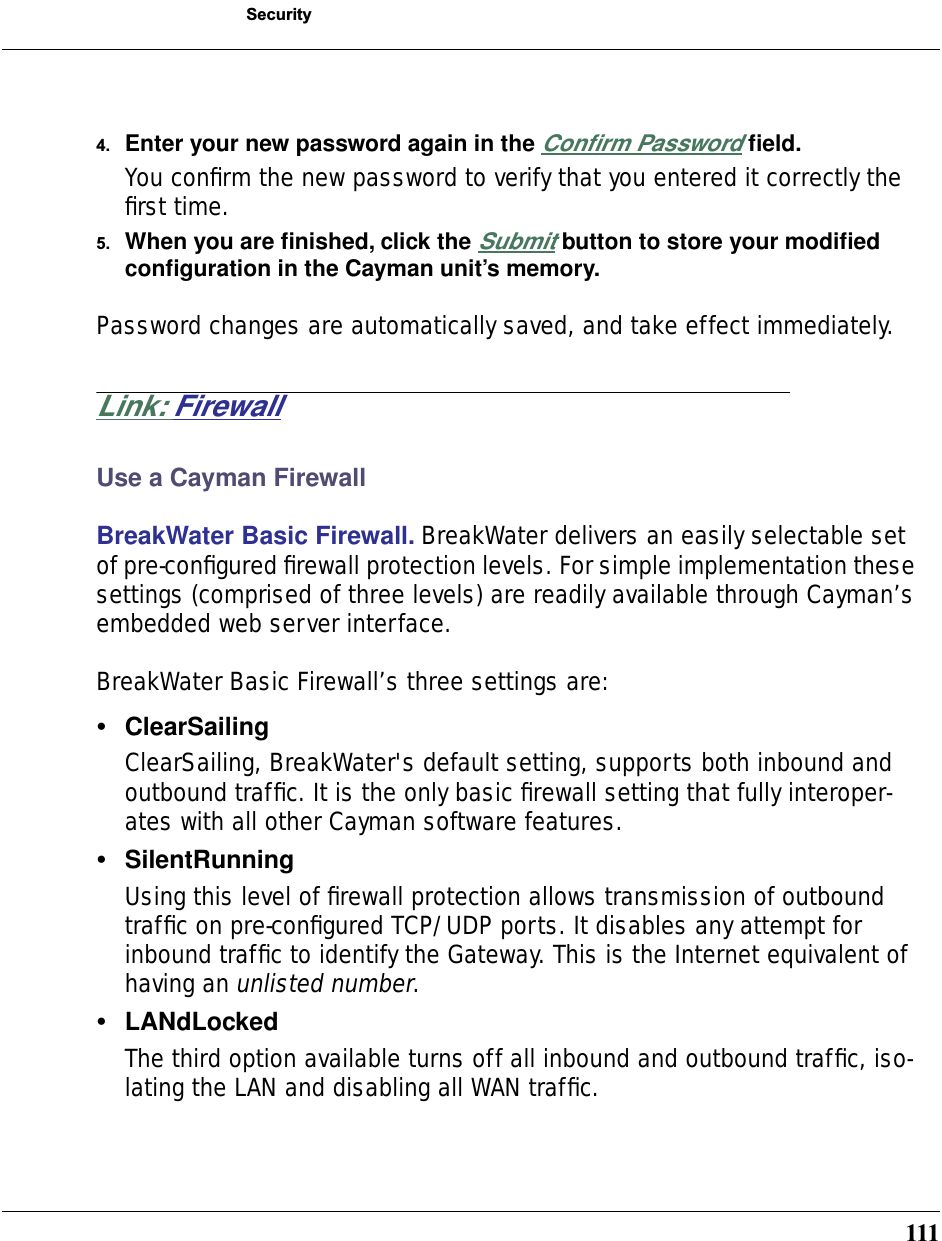
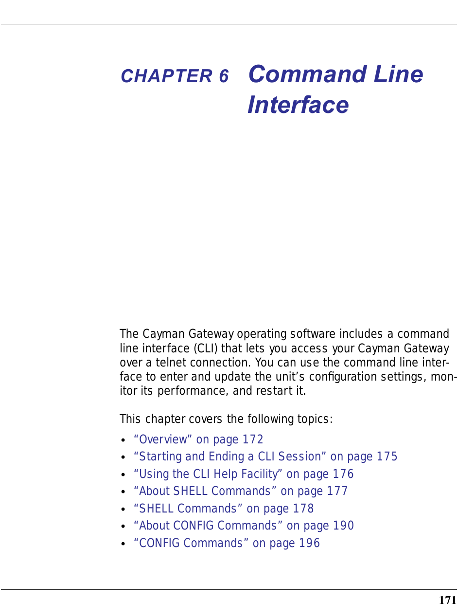
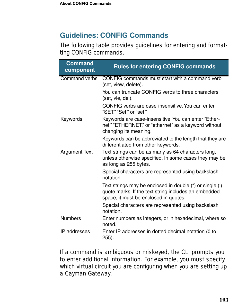
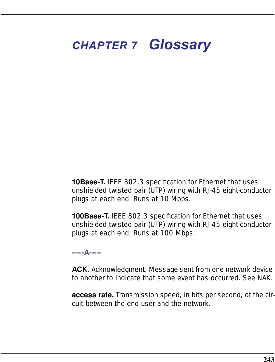
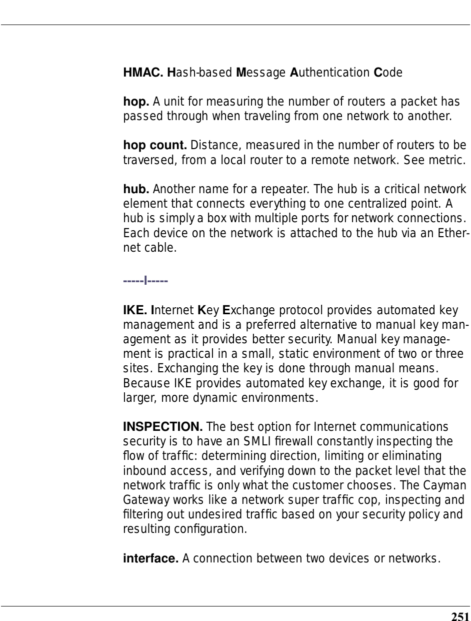
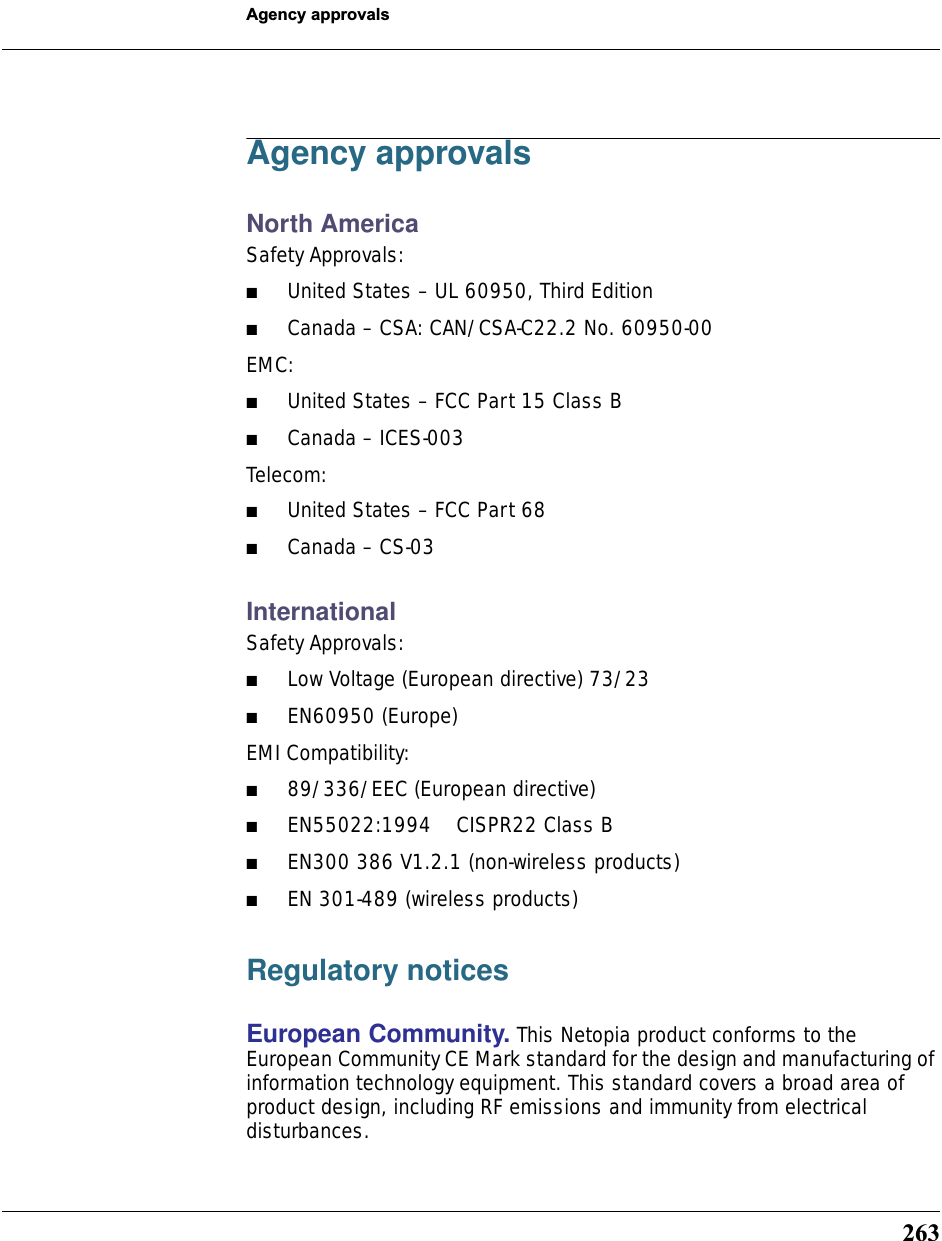
![14Command Line InterfaceSyntax conventions for the Cayman Gateway command line interface are as follows:TextThe words “Cayman Gateway” and “Gateway” refer to the Netopia Cayman Gateway.The expressions “Release 7.2” and “R 7.2” refer to the most recent gener-ally available Cayman Operating System.Convention Descriptionstraight ([ ]) brackets in cmd line Optional command arguments curly ({ }) brackets, with values separated with vertical bars (|). Alternative values for an argument are presented in curly ({ }) brackets, with values separated with vertical bars (|).bold terminal type faceUser-entered textitalic terminal type faceVariables for which you supply your own values](https://usermanual.wiki/ARRIS/3387W/User-Guide-349176-Page-14.png)
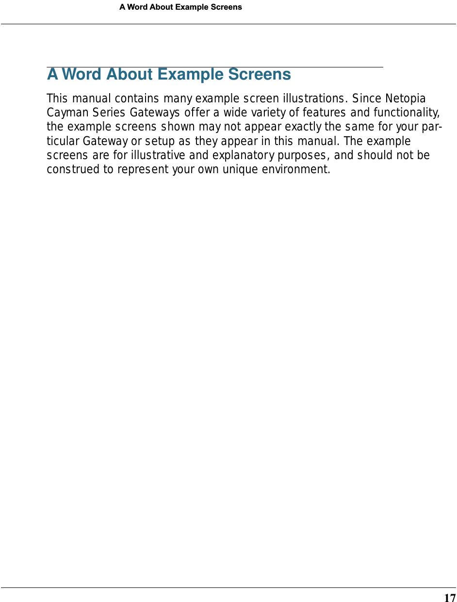

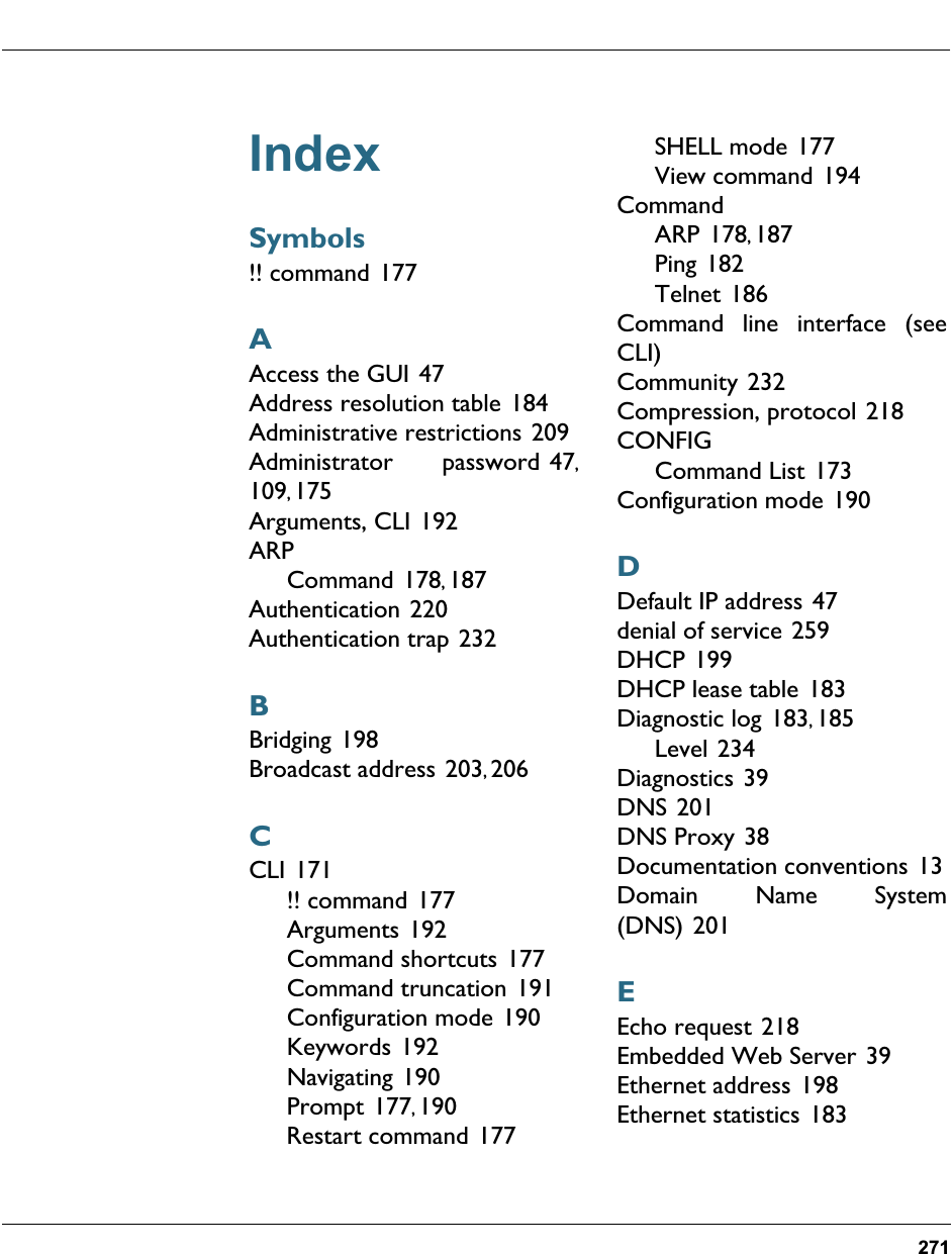
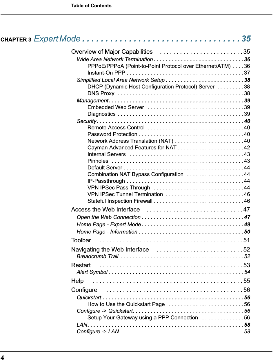
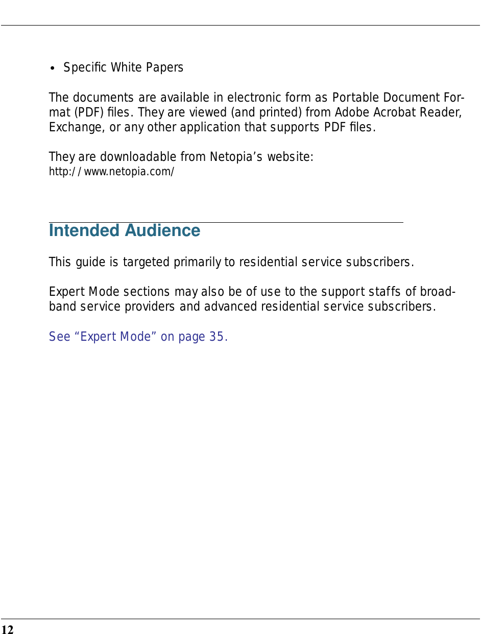
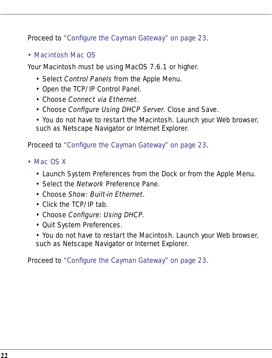
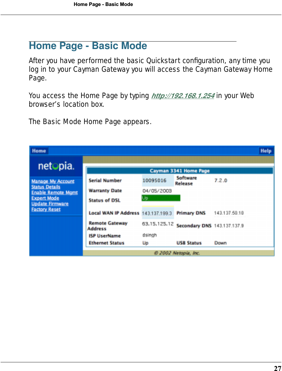
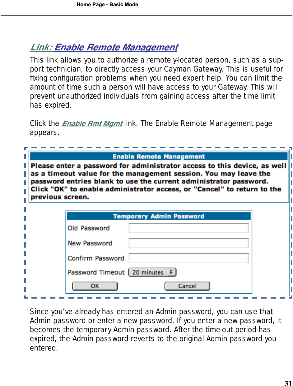
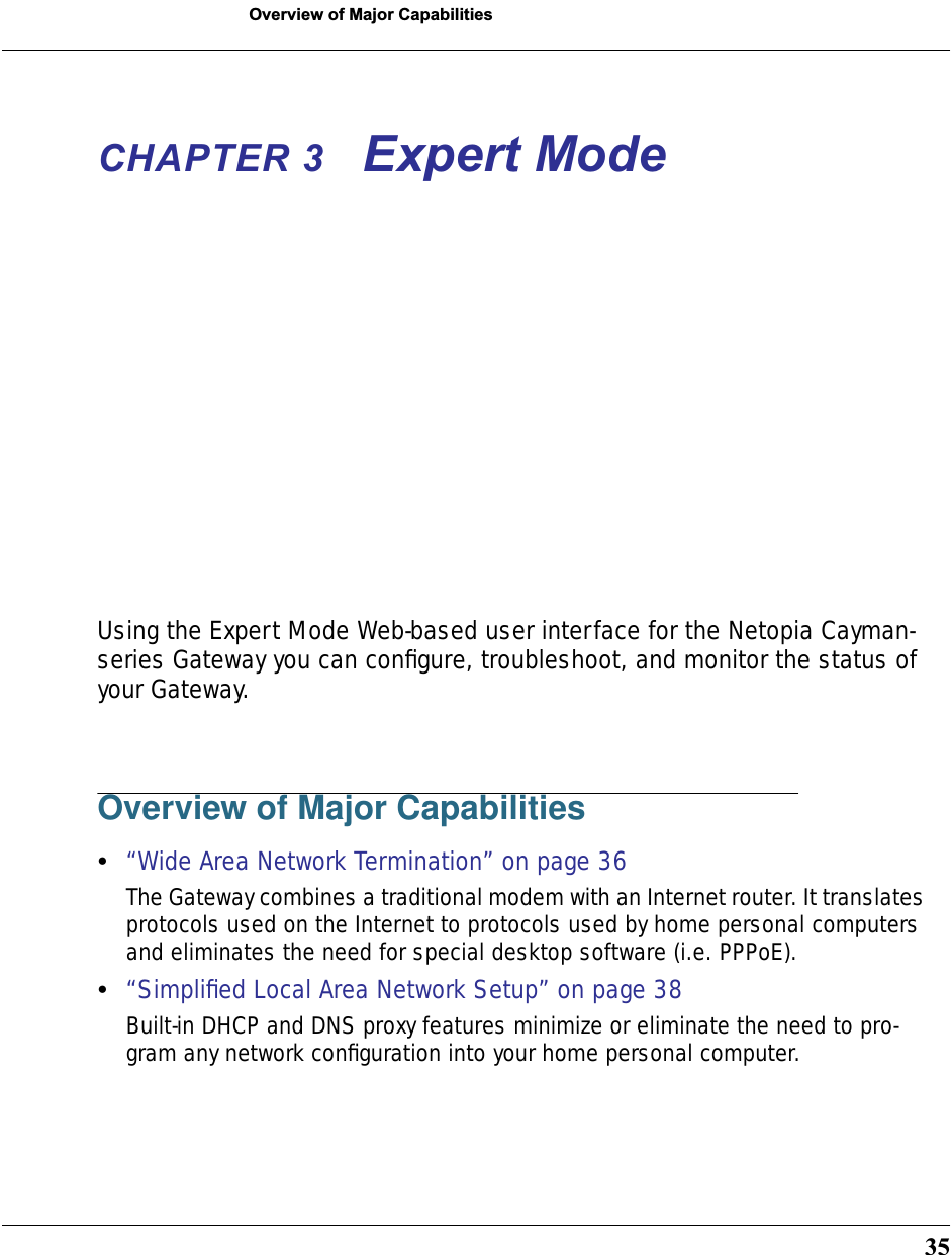
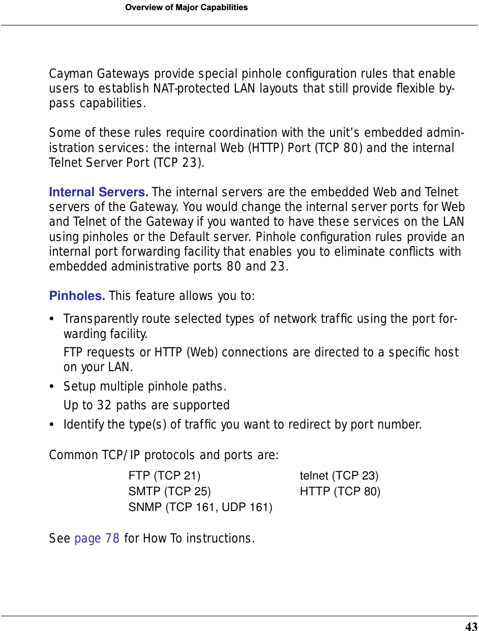
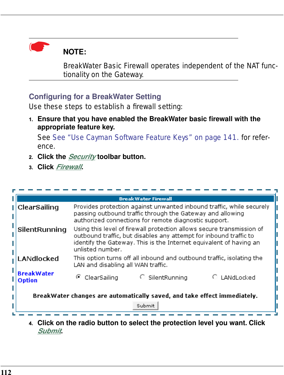
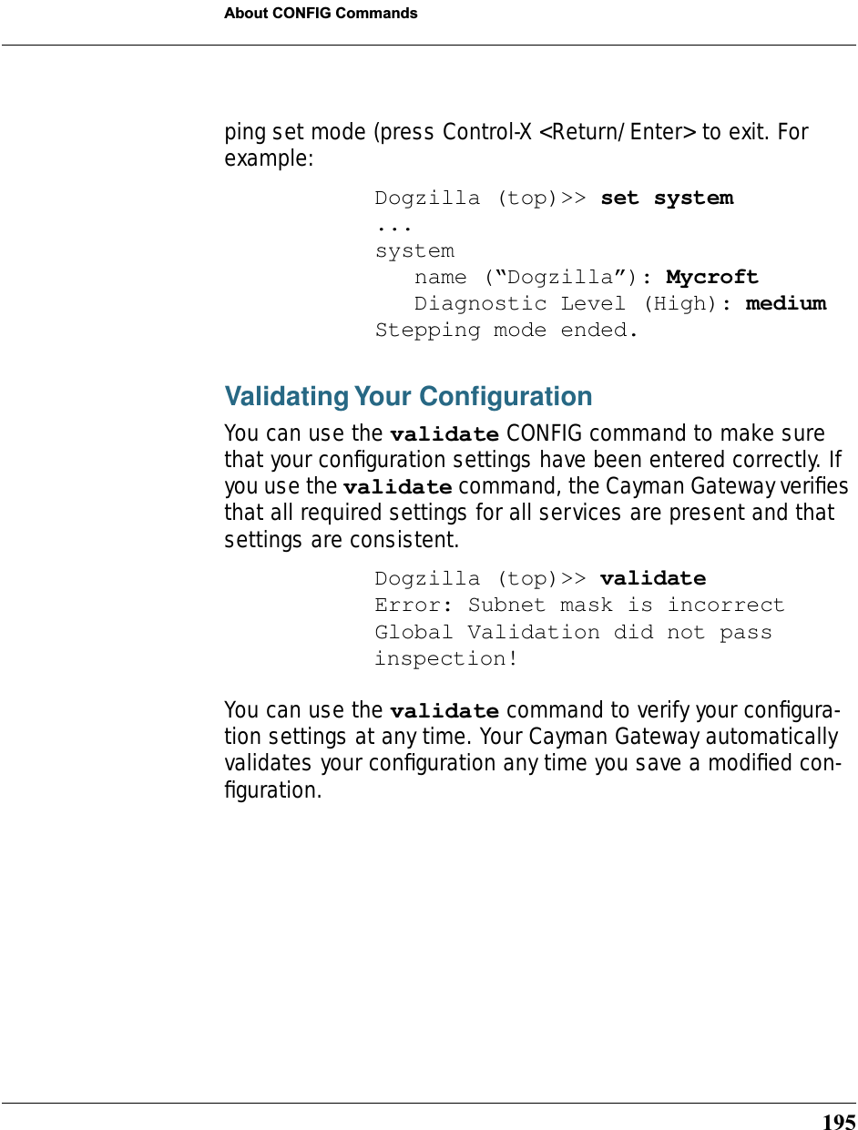
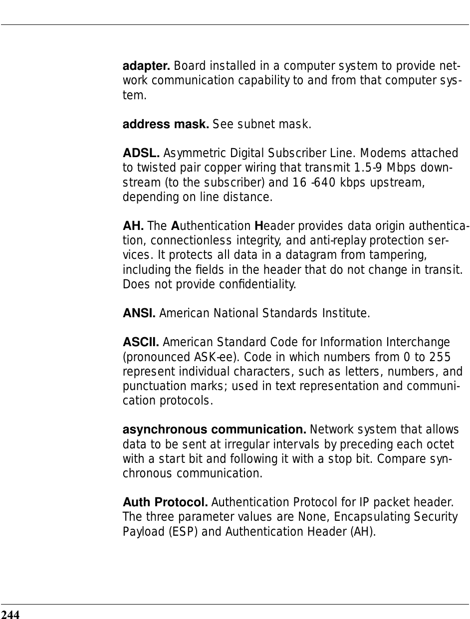
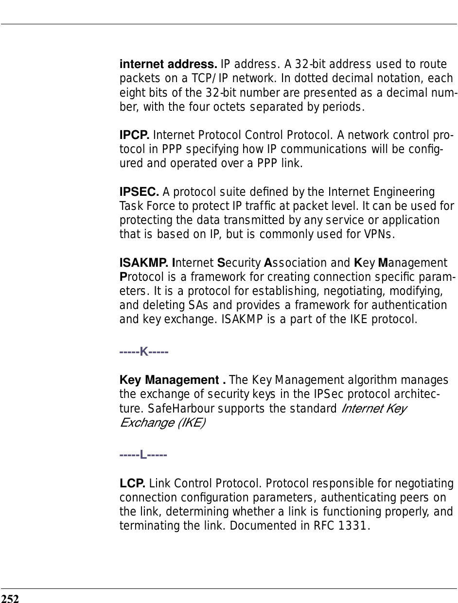
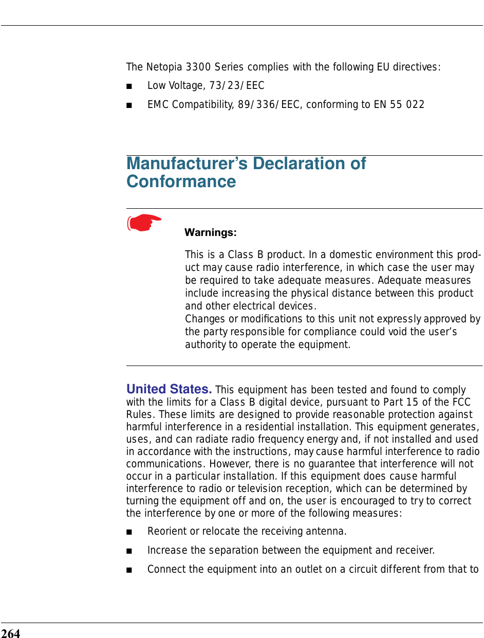
![21Set up the Cayman GatewaySet up the Cayman GatewayRefer to your Quickstart Guide for instructions on how to connect your Cay-man gateway to your power source, PC or local area network, and your Inter-net access point, whether it is a dedicated DSL outlet or a DSL or cable modem. Different Cayman Gateway models are supplied for any of these connections. Be sure to enable Dynamic Addressing on your PC. Perform the following:• Windows 95, 98 and ME• Right-Click on the Network Neighborhood icon on your Windows desk-top and select Properties from the pull-down menu.• In the list of network components, highlight the entry that says “TCP/IP ([your Ethernet card here])”.• Click the Properties button.• Click the Obtain an IP address automatically radio button. Click the DNS Configuration tab. Click the Disable DNS radio button. Click the Gateway tab and remove any installed Gateways. Click the OK button twice. When prompted, restart your PC.Proceed to “Configure the Cayman Gateway” on page 23.• Windows 2000 and XP• Right Click on the My Network Places icon on your Windows desktop and select Properties.• Select your Local Area Connection.• Right click on your Local Area Connection and select Properties.• Select Internet Protocol [TCP/IP].• Click the Properties button.• Click the Obtain IP address automatically radio button and the Obtain DNS server address automatically radio button. Click the OK button.](https://usermanual.wiki/ARRIS/3387W/User-Guide-349176-Page-21.png)
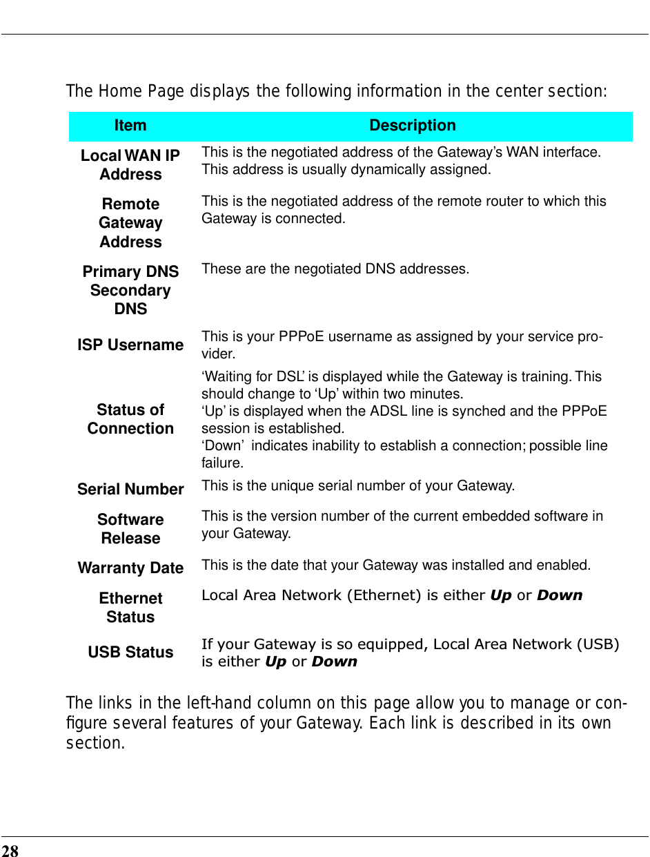
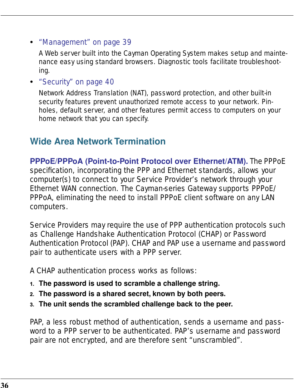
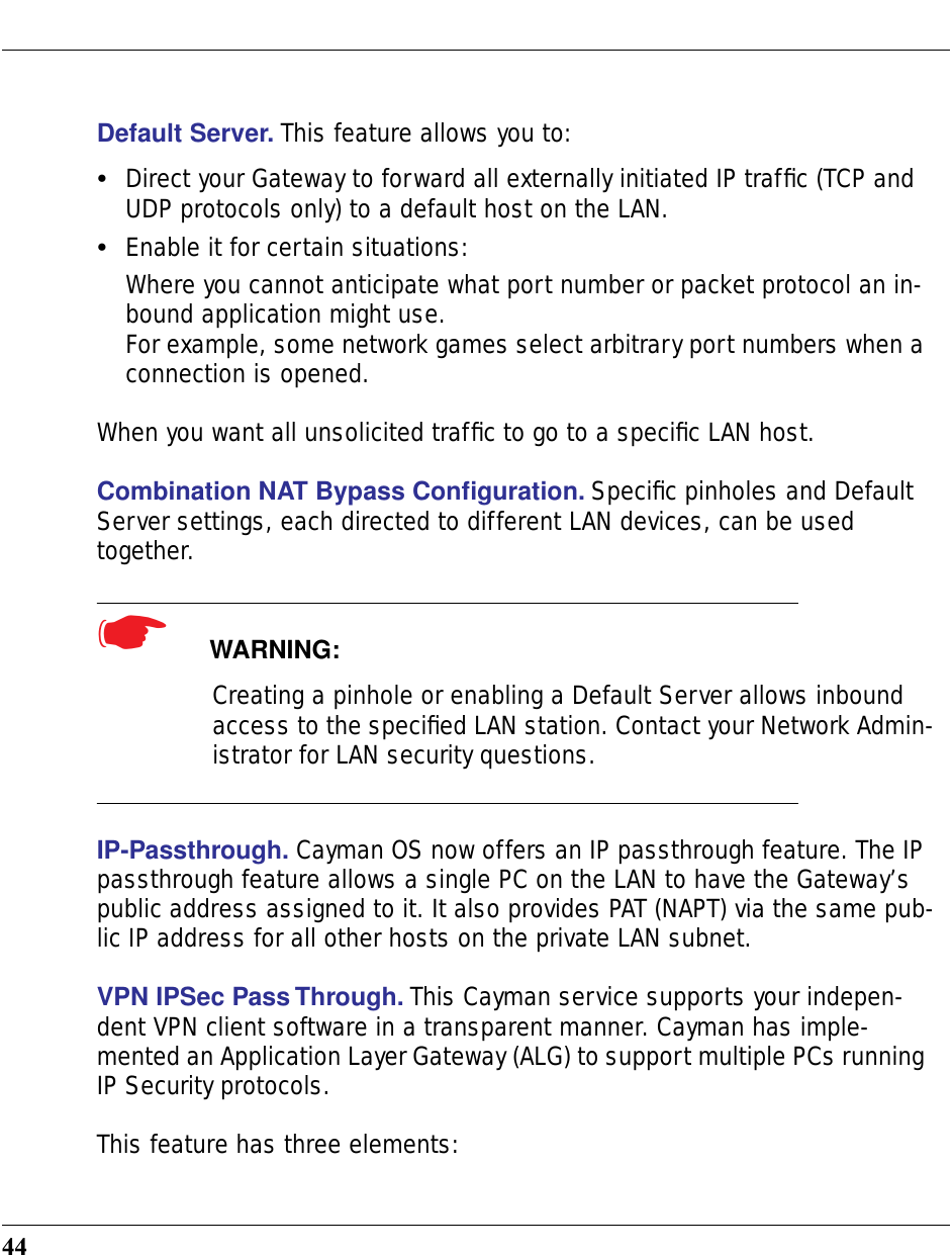
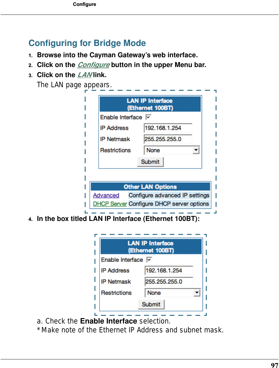
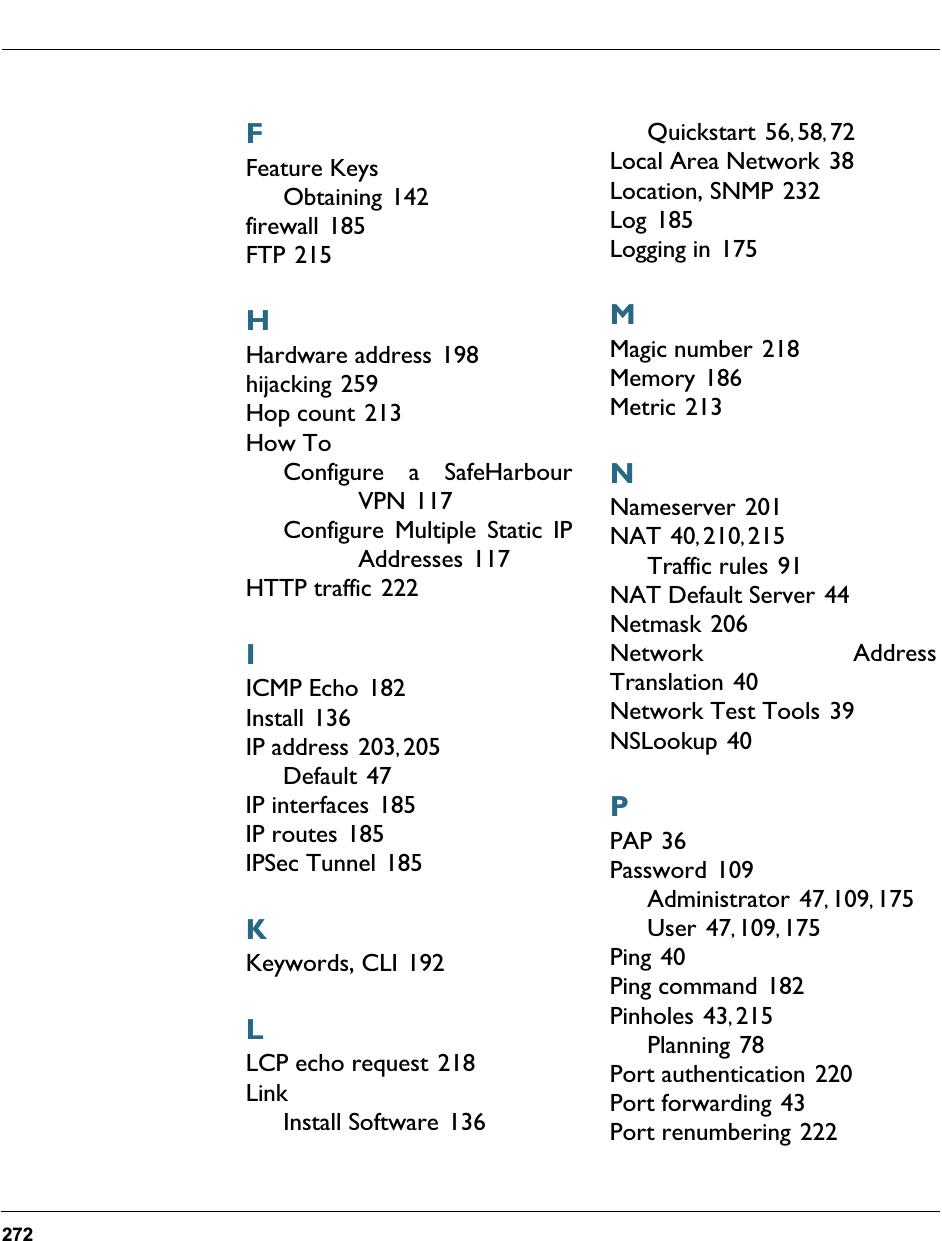
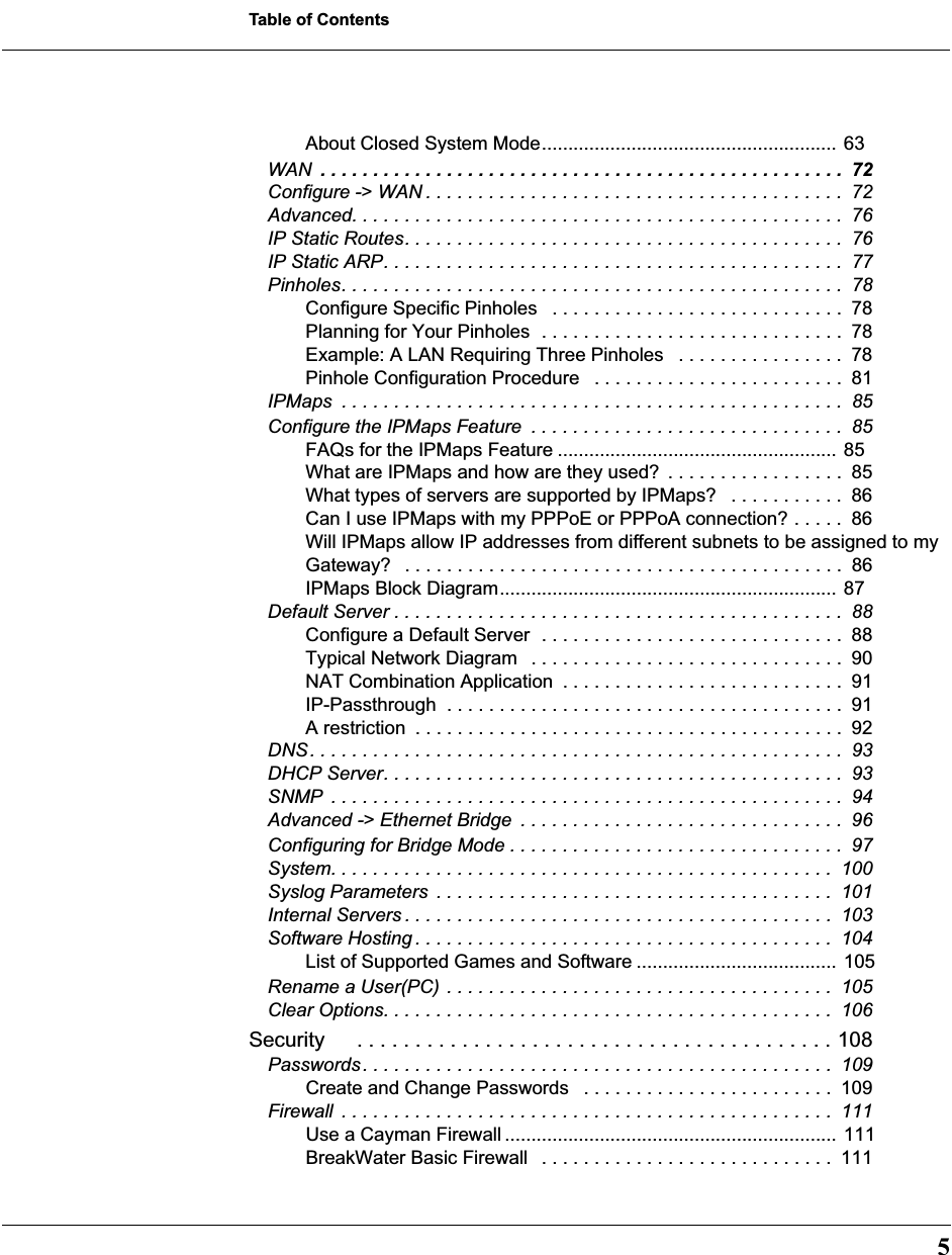
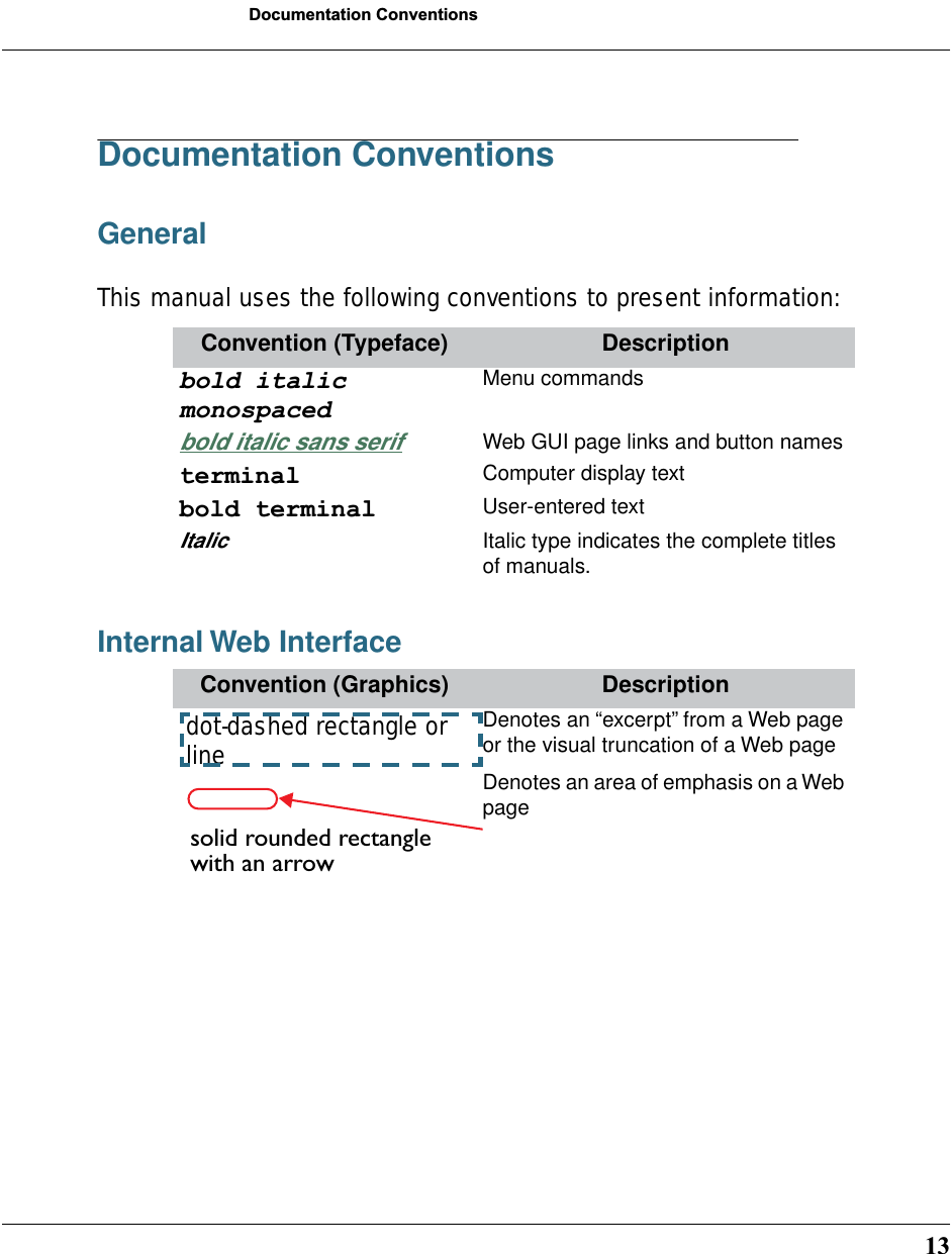
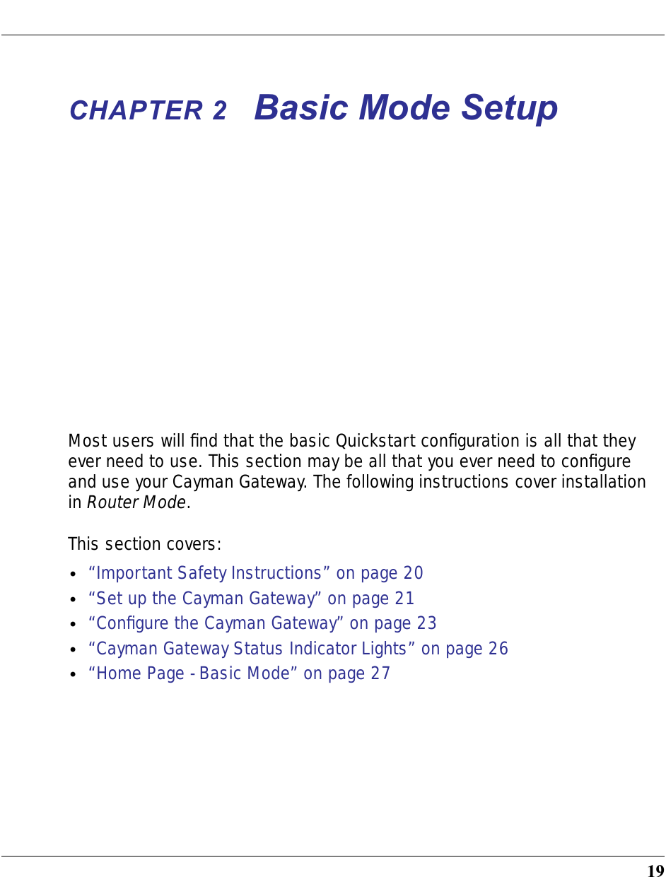
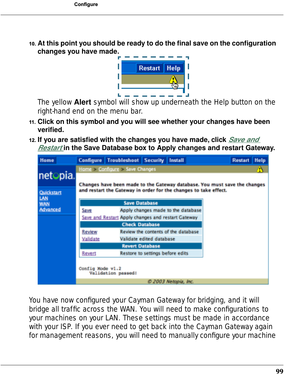
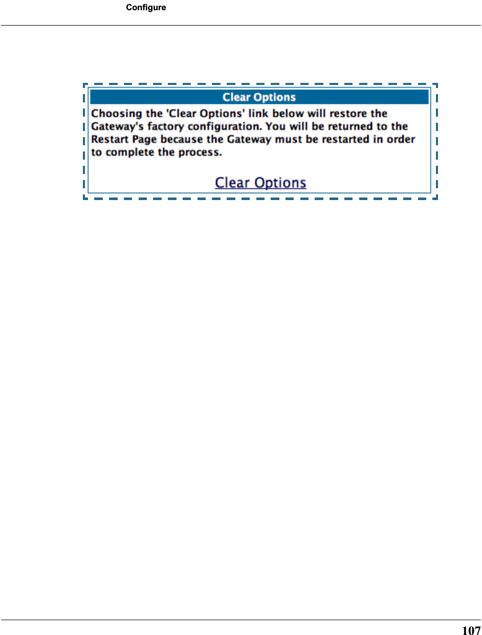
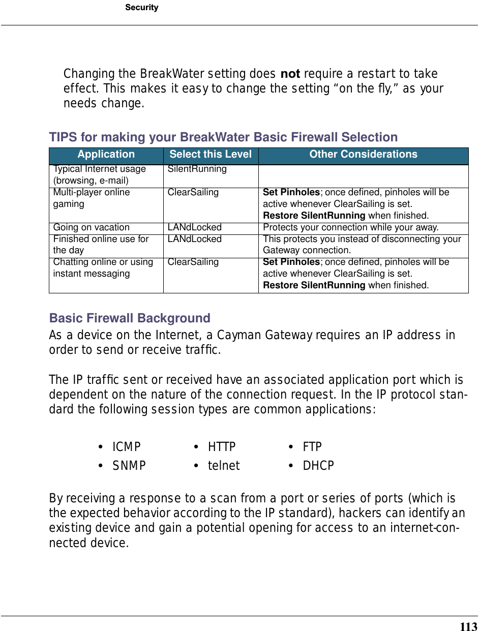
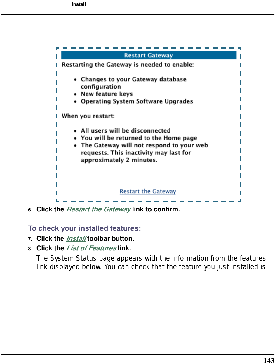
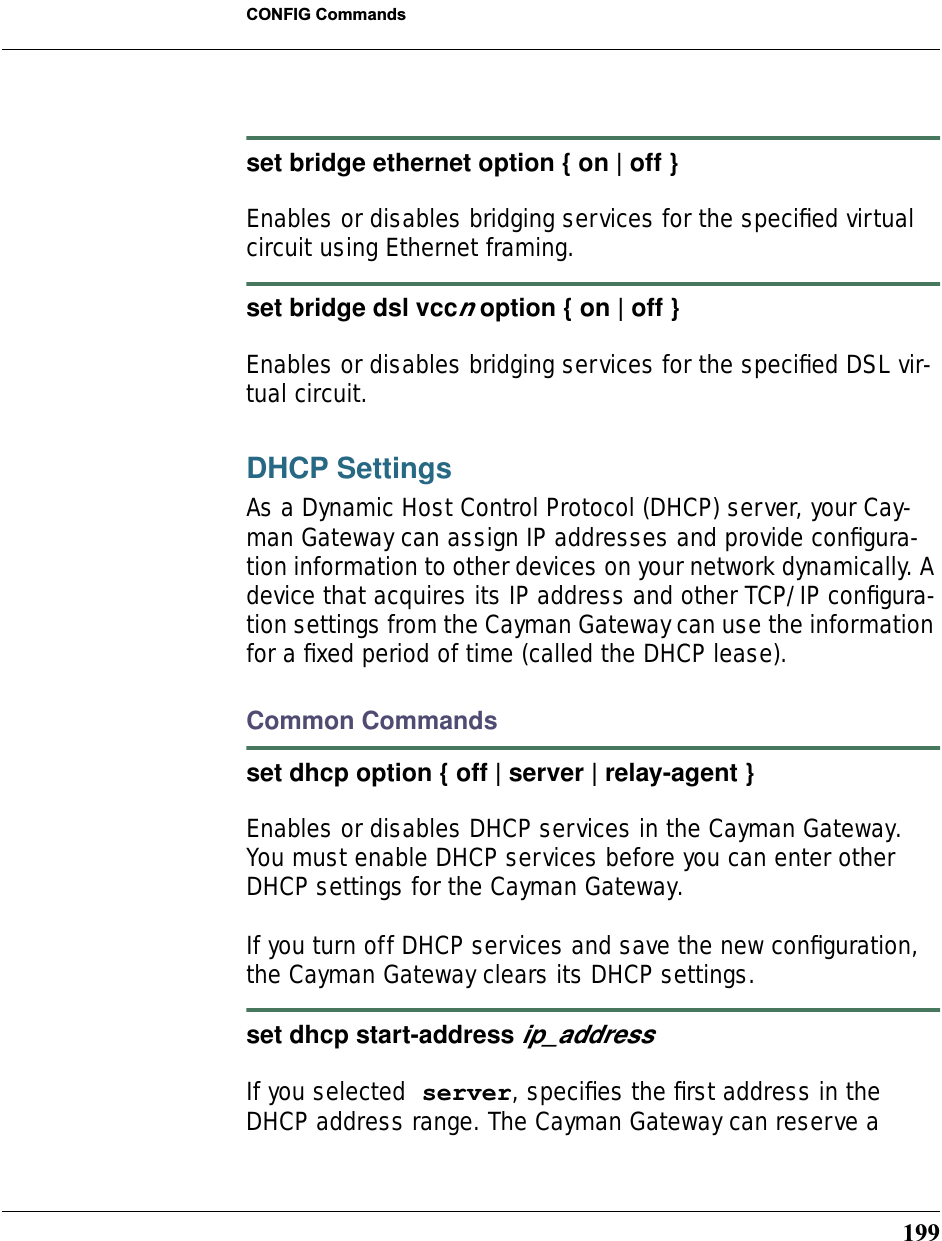
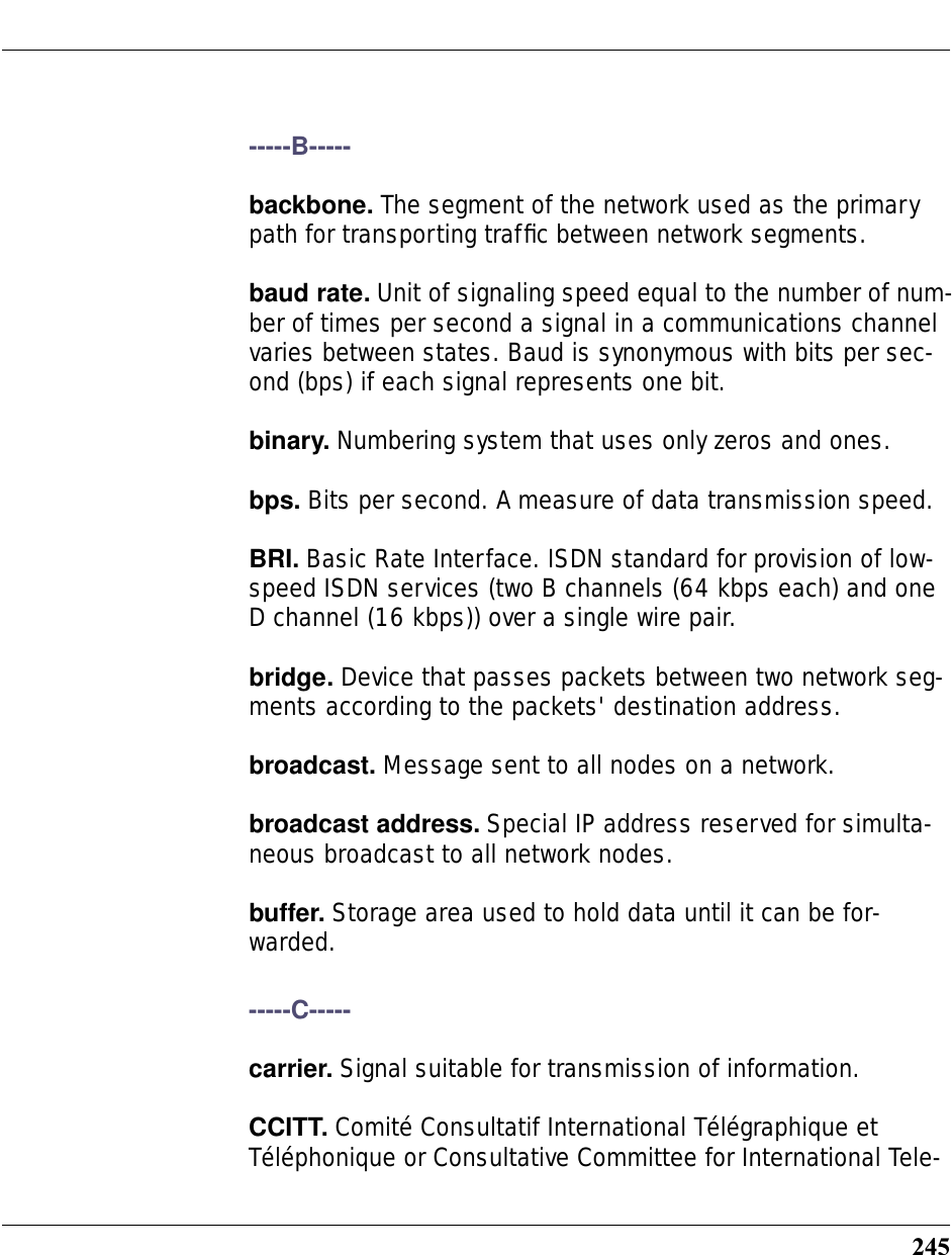
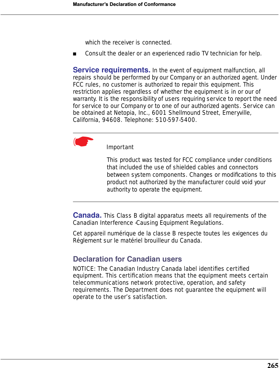
![98You can use this address to access the router in the future. b. Click Submit.5. Click on the Advanced link in the left-hand links toolbar.6. Under the heading of Services, click on the Ethernet Bridge link.The Ethernet Bridge page appears.7. Check the Enable Bridging Function selection.The window expands.8. Under Ethernet 100BT (LAN):Check the Enable Bridging on Port selection.9. Under RFC-1483 Bridged Ethernet vcc1 (WAN), or under PPP over Ether-net vcc1 (WAN) [as per your configuration]:a. Check the Enable Bridging on Port selection.b. Click Submit.](https://usermanual.wiki/ARRIS/3387W/User-Guide-349176-Page-98.png)
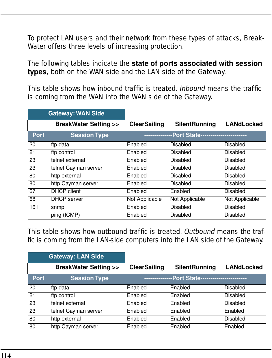


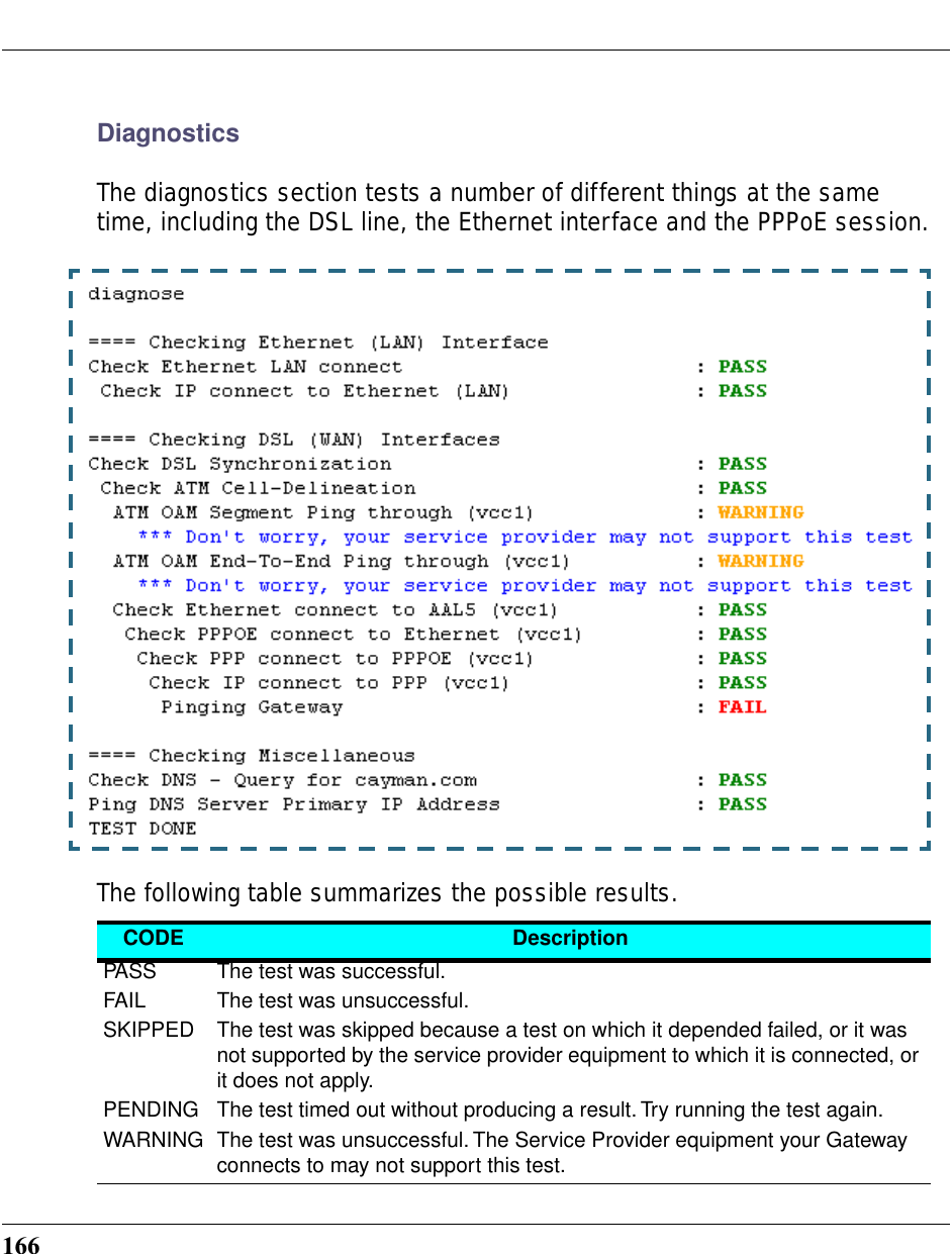
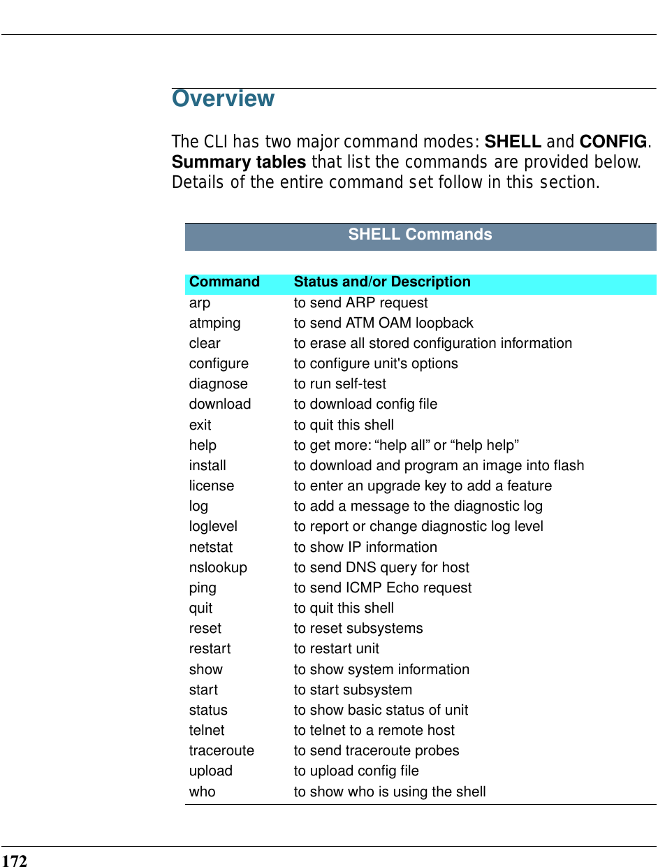
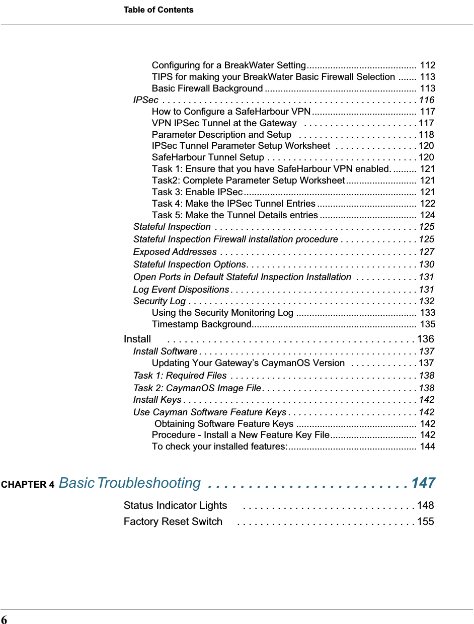
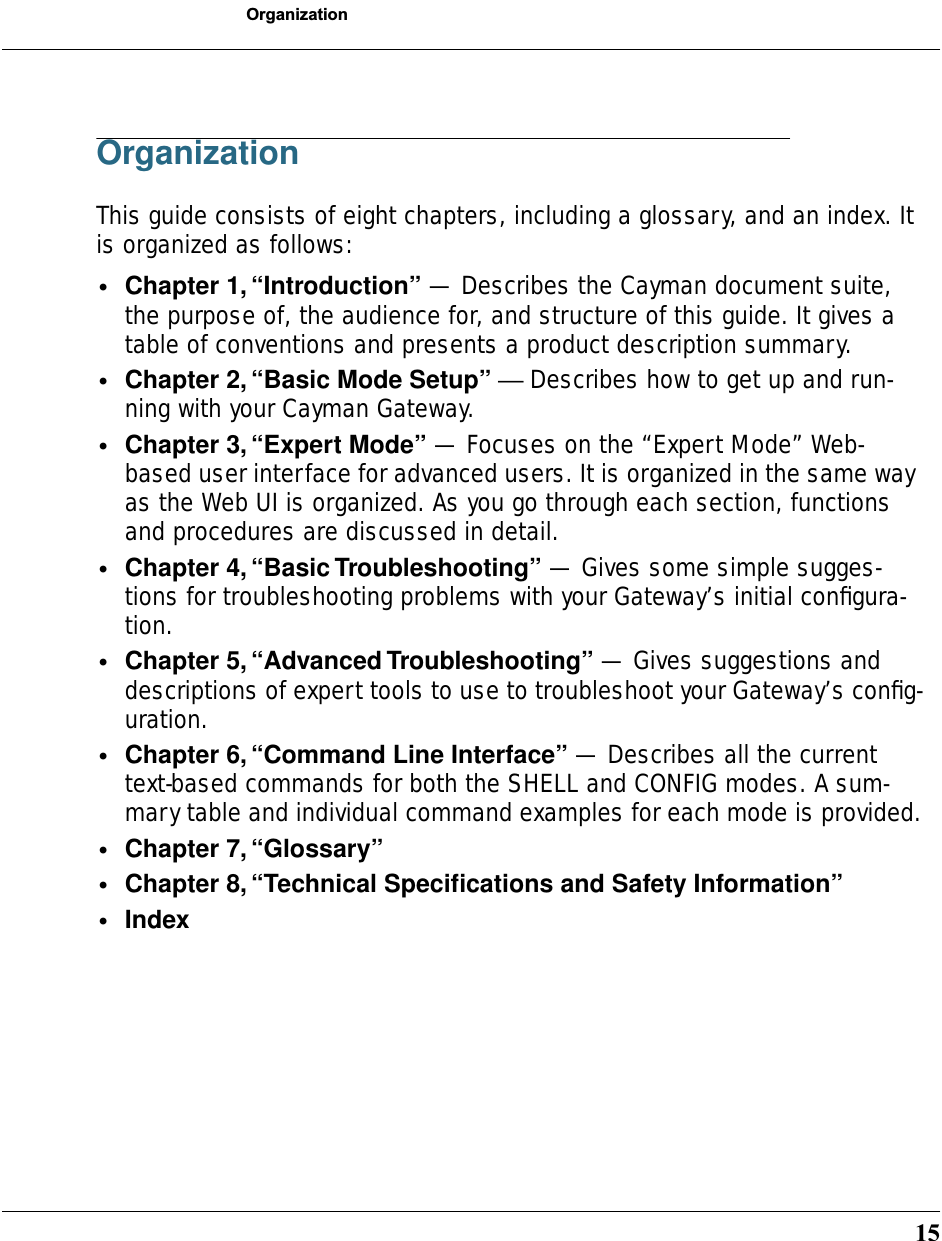
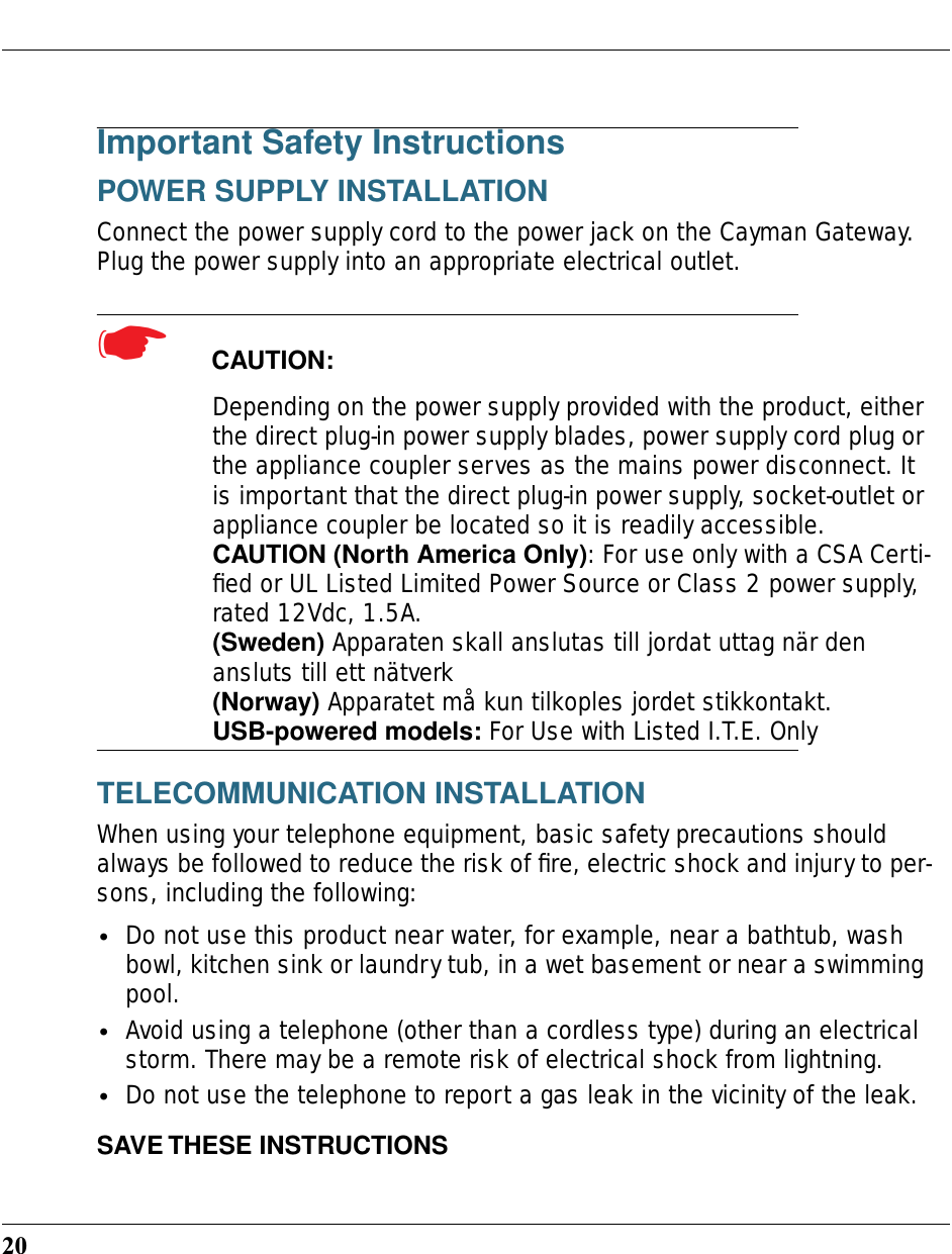
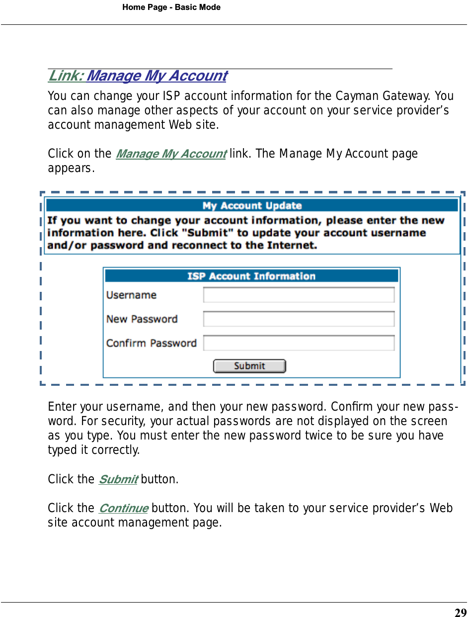
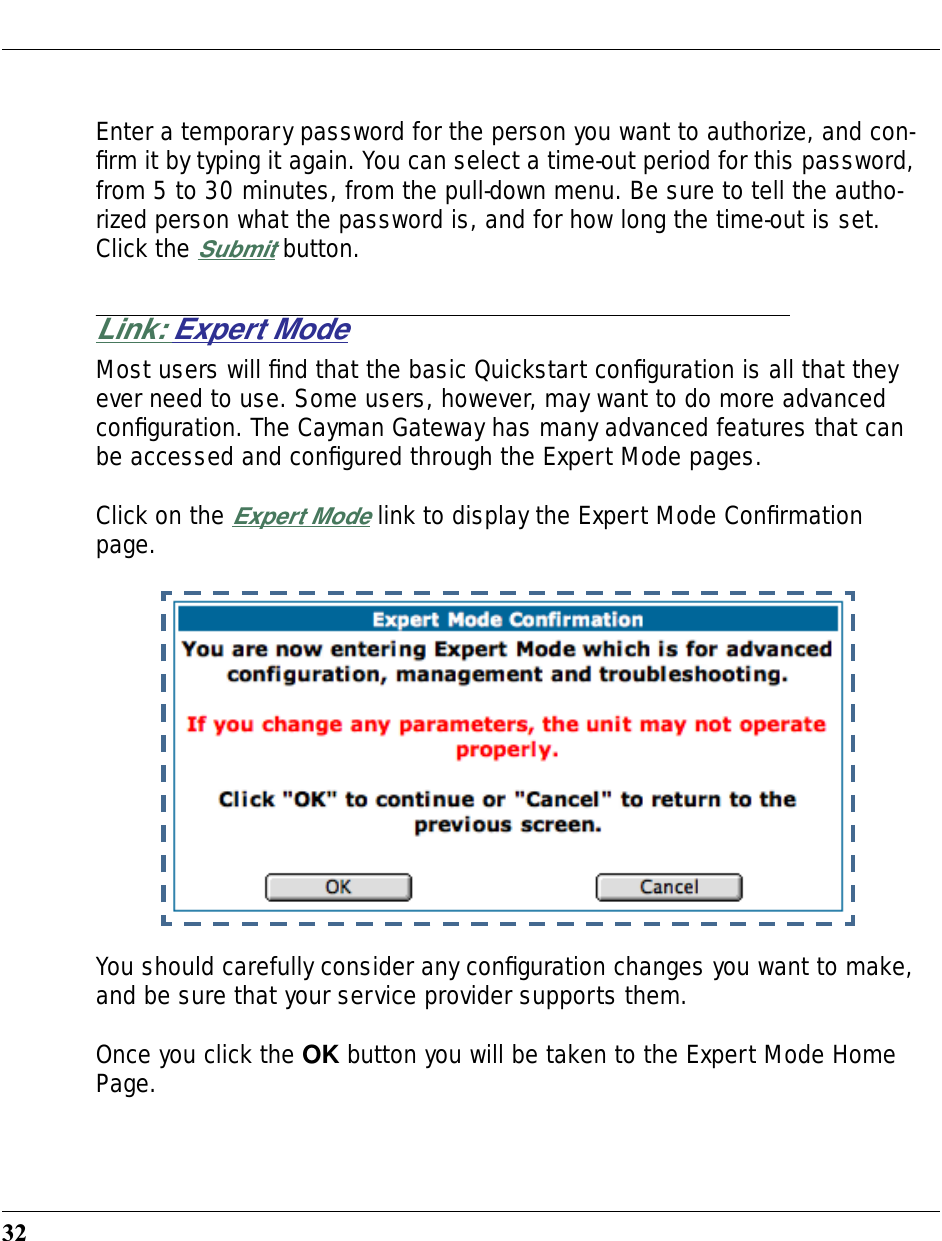
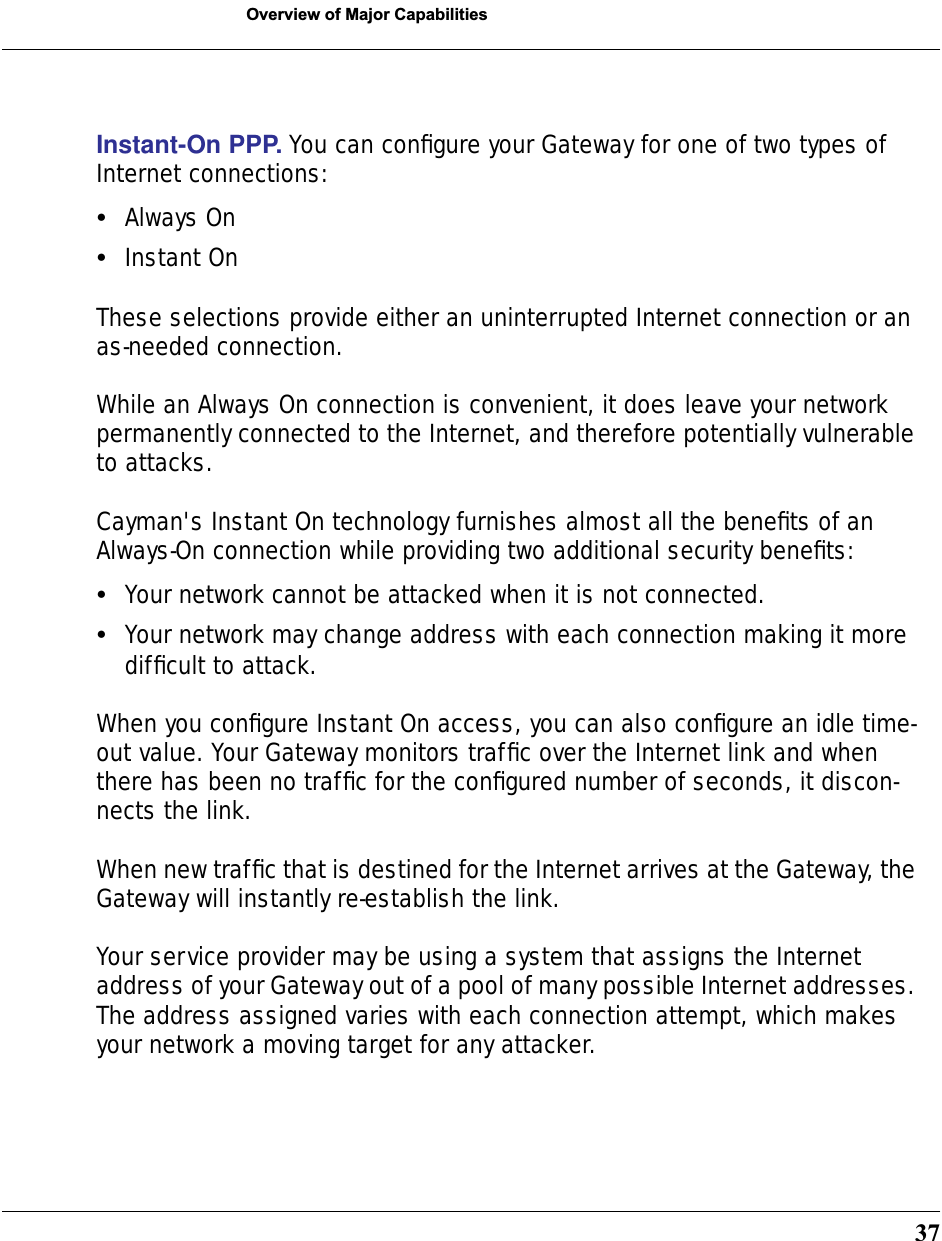
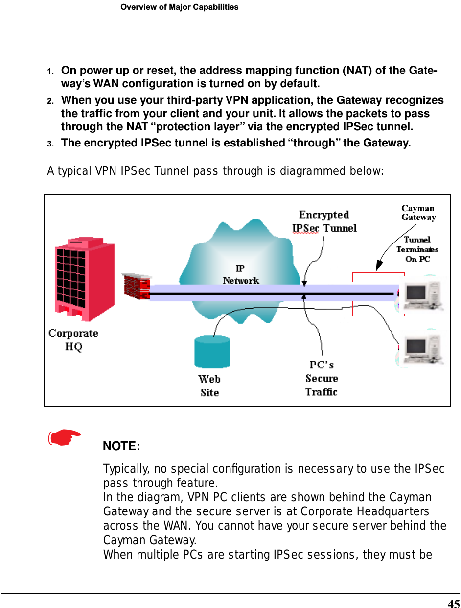
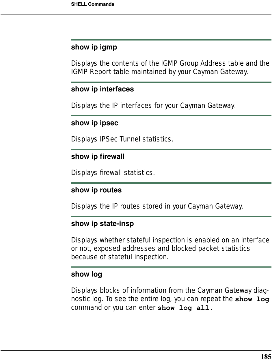
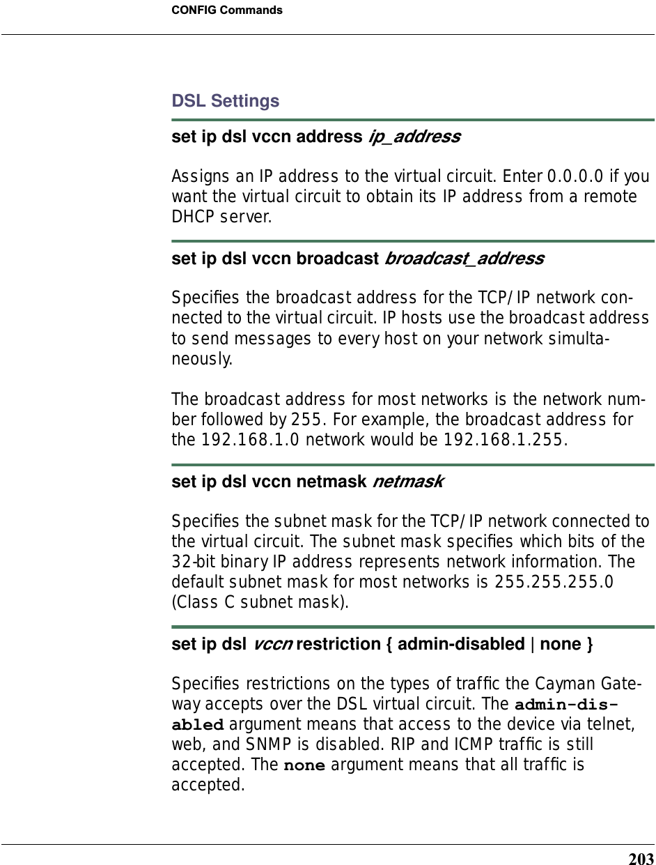
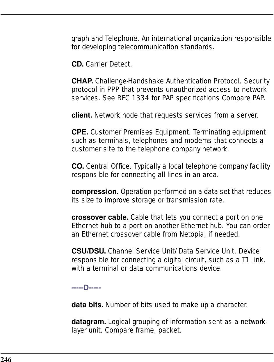
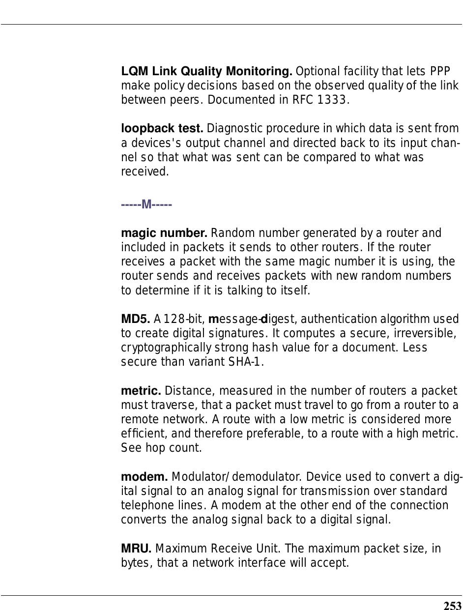
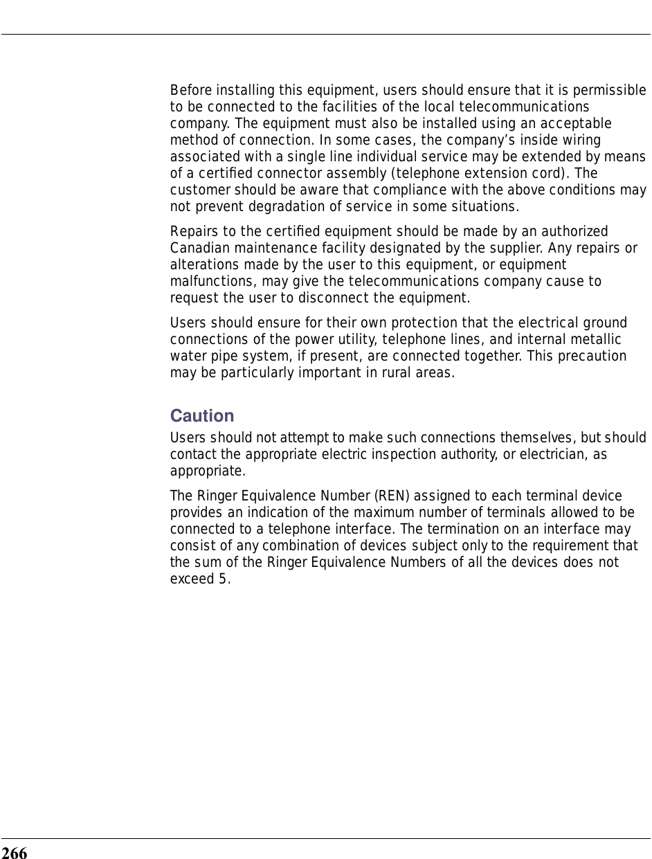
![178SHELL CommandsCommon Commandsarp nnn.nnn.nnn.nnnSends an Address Resolution Protocol (ARP) request to match the nnn.nnn.nnn.nnn IP address to an Ethernet hardware address.clear [yes]Clears the configuration settings in a Cayman Gateway. If you do not use the optional yes qualifier, you are prompted to con-firm the clear command.configurePuts the command line interface into Configure mode, which lets you configure your Cayman Gateway with Config com-mands. Config commands are described starting on page 173. diagnoseRuns a diagnostic utility to conduct a series of internal checks and loopback tests to verify network connectivity over each interface on your Cayman Gateway. The console displays the results of each test as the diagnostic utility runs. If one test is dependent on another, the diagnostic utility indents its entry in the console window. For example, the diagnostic utility indents the Check IP connect to Ethernet (LAN) entry, since that test will not run if the Check Ethernet LAN Connect test fails.](https://usermanual.wiki/ARRIS/3387W/User-Guide-349176-Page-176.png)
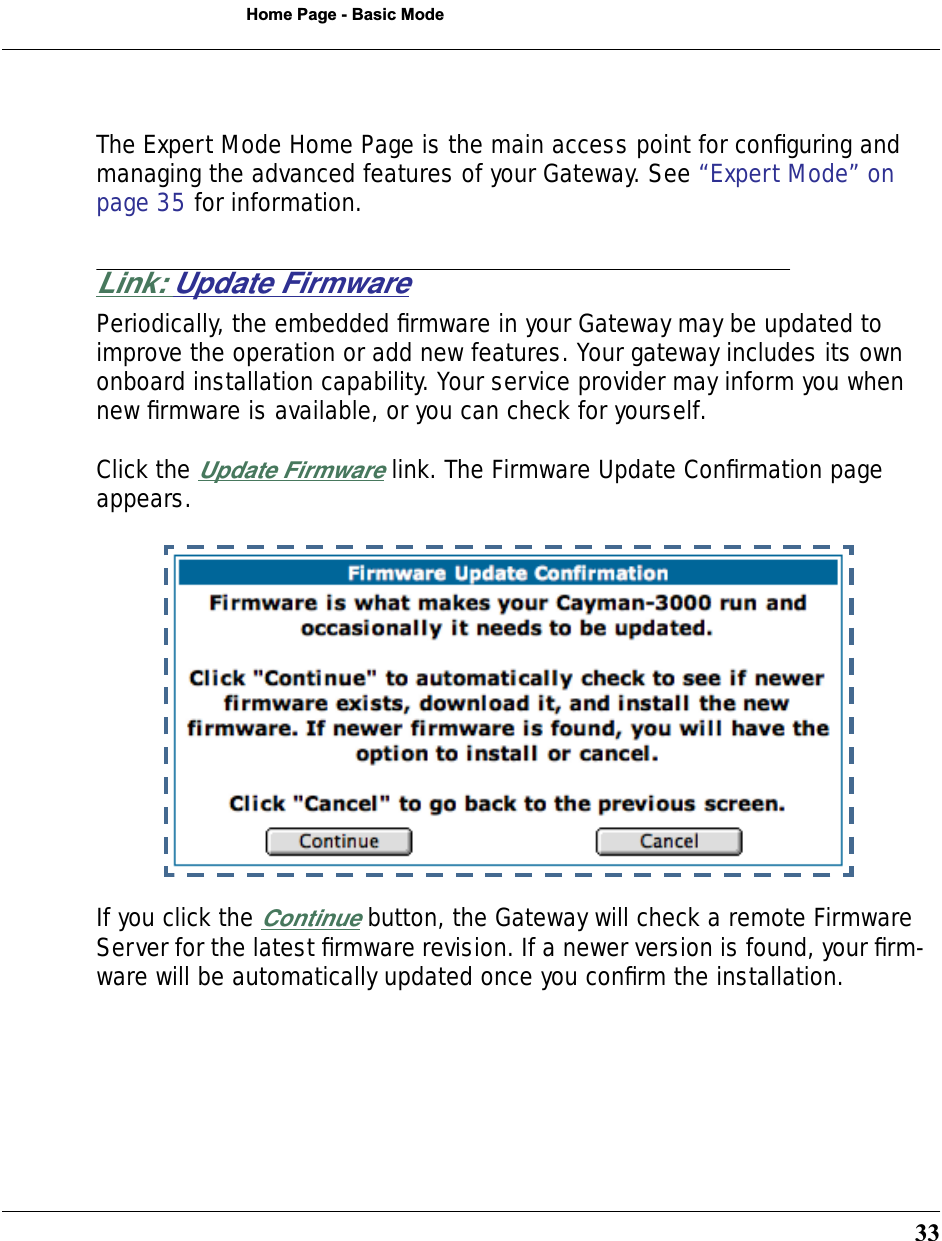
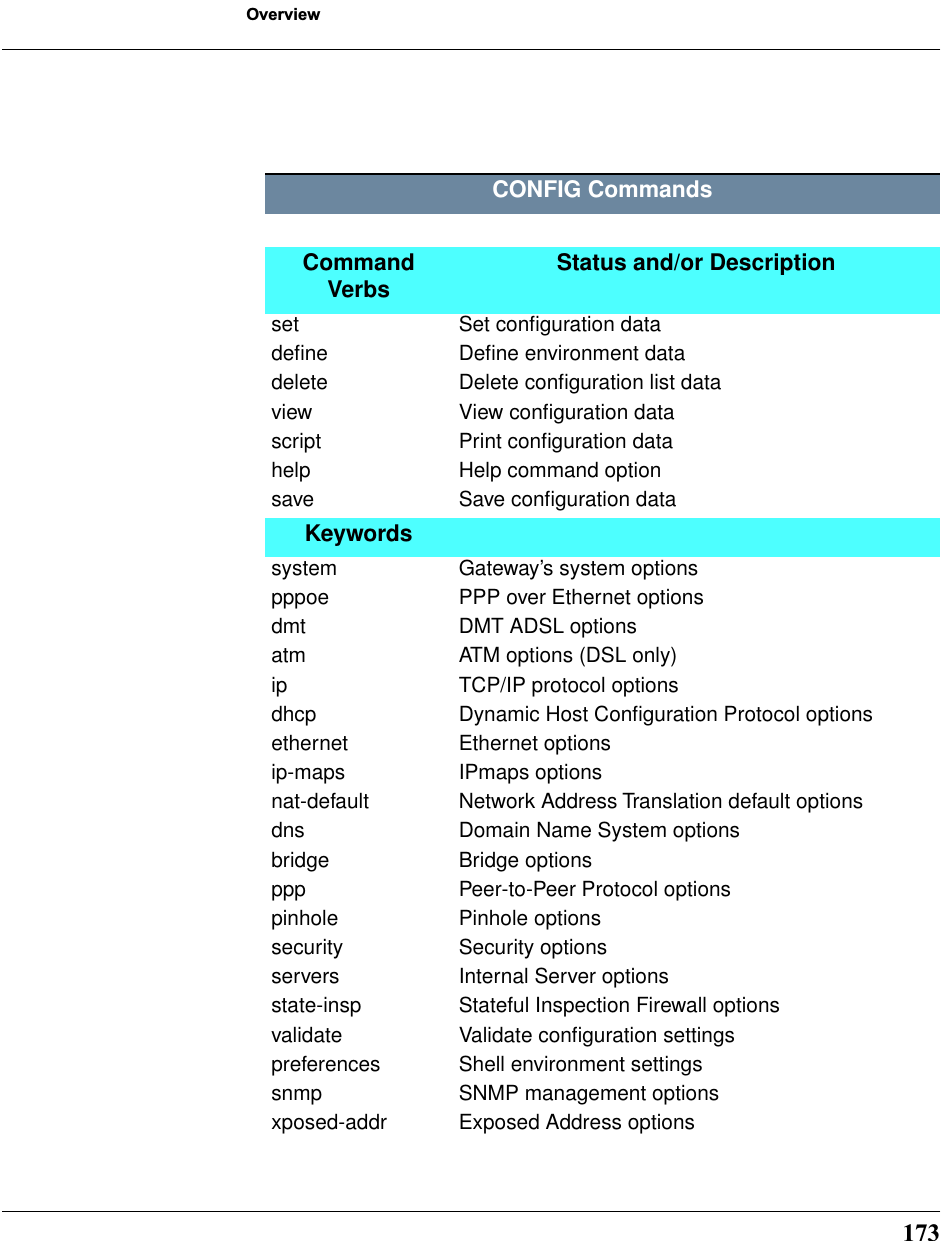
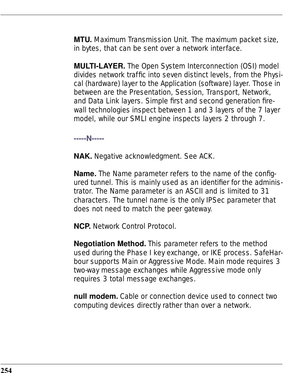
![179SHELL CommandsEach test generates one of the following result codes:download [server_address ] [filename] [confirm]This command installs a file of configuration parameters into the Cayman Gateway from a TFTP (Trivial File Transfer Protocol) server. The TFTP server must be accessible on your Ethernet network.You can include one or more of the following arguments with the download command. If you omit arguments, the console prompts you for this information.•The server_address argument identifies the IP address of the TFTP server from which you want to copy the Cayman Gateway configuration file. •The filename argument identifies the path and name of the configuration file on the TFTP server. •If you include the optional confirm keyword, the download begins as soon as all information is entered.install [server_address] [filename] [confirm]Downloads a new version of the Cayman Gateway operating software from a TFTP (Trivial File Transfer Protocol) server, vali-dates the software image, and programs the image into the CODE DescriptionPASS The test was successful.FAIL The test was unsuccessful.SKIPPED The test was skipped because a test on which it depended failed, or because the test did not apply to your particular setup or model.PENDING The test timed out without producing a result. Try running the test again.](https://usermanual.wiki/ARRIS/3387W/User-Guide-349176-Page-177.png)
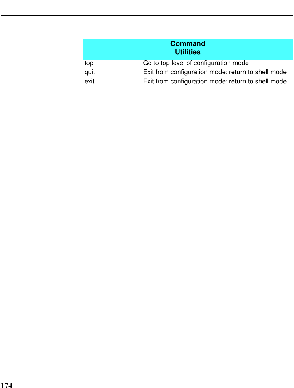
![180Cayman Gateway memory. After you install new operating soft-ware, you must restart the Cayman Gateway.The server_address argument identifies the IP address of the TFTP server on which your Cayman Gateway operating soft-ware is stored. The filename argument identifies the path and name of the operating software file on the TFTP server.If you include the optional keyword confirm, you will not be prompted to confirm whether or not you want to perform the operation.license [key]This command installs a software upgrade key. An upgrade key is a purchased item, based on the serial number of the gate-way.log message_stringAdds the message in the message_string argument to the Cayman Gateway diagnostic log.loglevel [level] Displays or modifies the types of log messages you want the Cayman Gateway to record. If you enter the loglevel com-mand without the optional level argument, the command line interface displays the current log level setting. You can enter the loglevel command with the level argu-ment to specify the types of diagnostic messages you want to record. All messages with a level number equal to or greater than the level you specify are recorded. For example, if you specify loglevel 3, the diagnostic log will retain high-level infor-](https://usermanual.wiki/ARRIS/3387W/User-Guide-349176-Page-178.png)
![182ping [-s size] [-c count]{ hostname | ip_address }Causes the Cayman Gateway to issue a series of ICMP Echo requests for the device with the specified name or IP address. •The hostname argument is the name of the device you want to ping; for example, ping ftp.netopia.com.•The ip_address argument is the IP address, in dotted dec-imal notation, of the device you want to locate. If a host using the specified name or IP address is active, it returns one or more ICMP Echo replies, confirming that it is accessi-ble from your network.•The -s size argument lets you specify the size of the ICMP packet.•The -c count argument lets you specify the number of ICMP packets generated for the ping request. Values greater than 250 are truncated to 250.You can use the ping command to determine whether a host-name or IP address is already in use on your network. You can-not use the ping command to ping the Cayman Gateway’s own IP address.quit Exits the Cayman Gateway command line interface.reset arp Clears the Address Resolution Protocol (ARP) cache on your unit.](https://usermanual.wiki/ARRIS/3387W/User-Guide-349176-Page-180.png)
![183SHELL Commandsreset crash Clears crash-dump information, which identifies the contents of the Cayman Gateway registers at the point of system malfunc-tion.reset dhcp serverClears the DHCP lease table in the Cayman Gateway.reset enetResets Ethernet statistics to zeroreset ipmapClears the IPMap table (NAT).reset logRewinds the diagnostic log display to the top of the existing Cayman Gateway diagnostic log. The reset log command does not clear the diagnostic log. The next show log command will display information from the beginning of the log file.reset security-logClears the security monitoring log to make room to capture new entries. reset wan-users [all | ip-address]This function disconnects the specified WAN User to allow for other users to access the WAN. This function is only available if](https://usermanual.wiki/ARRIS/3387W/User-Guide-349176-Page-181.png)
![184the number of WAN Users is restricted and NAT is on. Use the all parameter to disconnect all users. If you logon as Admin you can disconnect any or all users. If you logon as User, you can only disconnect yourself. restart [seconds]Restarts your Cayman Gateway. If you include the optional seconds argument, your Cayman Gateway will restart when the specified number of seconds have elapsed. You must enter the complete restart command to initiate a restart.show bridge interfacesDisplays bridge interfaces maintained by the Cayman Gateway.show bridge tableDisplays the bridging table maintained by the Cayman Gateway.show crashDisplays the most recent crash information, if any, for your Cay-man Gateway.show dhcp server leasesDisplays the DHCP leases stored in RAM by your Cayman Gate-way.show ip arpDisplays the Ethernet address resolution table stored in your Cayman Gateway.](https://usermanual.wiki/ARRIS/3387W/User-Guide-349176-Page-182.png)
![186show memory [all]Displays memory usage information for your Cayman Gateway. If you include the optional all argument, your Cayman Gateway will display a more detailed set of memory statistics.show pppoeDisplays status information for each PPP socket, such as the socket state, service names, and host ID values.show rulesetlistDisplays all the available application hosting rules in the sys-tem. See “Software Hosting” on page 104.show statusDisplays the current status of a Cayman Gateway, the device's hardware and software revision levels, a summary of errors encountered, and the length of time the Cayman Gateway has been running since it was last restarted. Identical to the sta-tus command.telnet { hostname | ip_address } [port] Lets you open a telnet connection to the specified host through your Cayman Gateway.•The hostname argument is the name of the device to which you want to connect; for example, telnet ftp.cayman.com.•The ip_address argument is the IP address, in dotted dec-imal notation, of the device to which you want to connect.•The port argument is the number of t he port over which you want to open a telnet session.](https://usermanual.wiki/ARRIS/3387W/User-Guide-349176-Page-184.png)
![187SHELL Commandsupload [server_address] [filename] [confirm]Copies the current configuration settings of the Cayman Gate-way to a TFTP (Trivial File Transfer Protocol) server. The TFTP server must be accessible on your Ethernet network. The server_address argument identifies the IP address of the TFTP server on which you want to store the Cayman Gateway settings. The filename argument identifies the path and name of the configuration file on the TFTP server. If you include the optional confirm keyword, you will not be prompted to confirm whether or not you want to perform the operation.who Displays the names of the current shell and PPP users. WAN Commandsatmping vccn [ segment | end-to-end ]Lets you check the ATM connection reachability and network connectivity. This command sends five Operations, Administra-tion, and Maintenance (OAM) loopback calls to the specified vpi/vci destination. There is a five second total timeout interval.Use the segment argument to ping a neighbor switch.Use the end-to-end argument to ping a remote end node.reset dhcp client release [ vcc-id ]Releases the DHCP lease the Cayman Gateway is currently using to acquire the IP settings for the specified DSL port. The vcc-id identifier is a letter in the range B-I. Enter the reset](https://usermanual.wiki/ARRIS/3387W/User-Guide-349176-Page-185.png)
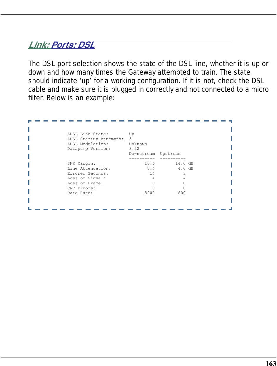
![188dhcp client release without the variable to see the letter assigned to each virtual circuit.reset dhcp client renew [ vcc-id ]Releases the DHCP lease the Cayman Gateway is currently using to acquire the IP settings for the specified DSL port. The vcc-id identifier is a letter in the range B-I. Enter the reset dhcp client release without the variable to see the letter assigned to each virtual circuit.reset dslResets any open DSL connection.reset ppp vccnResets the point-to-point connection over the specified virtual circuit. This command only applies to virtual circuits that use PPP framing.show atm [all]Displays ATM statistics for the Cayman Gateway. The optional all argument displays a more detailed set of ATM statistics.show dslDisplays DSL port statistics, such as upstream and down-stream connection rates and noise levels.](https://usermanual.wiki/ARRIS/3387W/User-Guide-349176-Page-186.png)
![189SHELL Commandsshow ppp [{ stats | lcp | ipcp }]Displays information about open PPP links. You can display a subset of the PPP statistics by including an optional stats, lcp, or ipcp argument for the show ppp command.start ppp vccnOpens a PPP link on the specified virtual circuit.](https://usermanual.wiki/ARRIS/3387W/User-Guide-349176-Page-187.png)
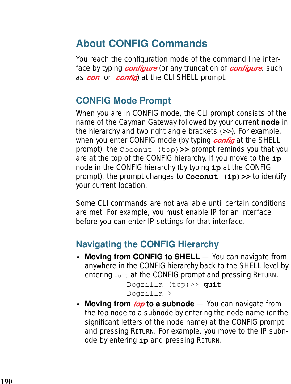
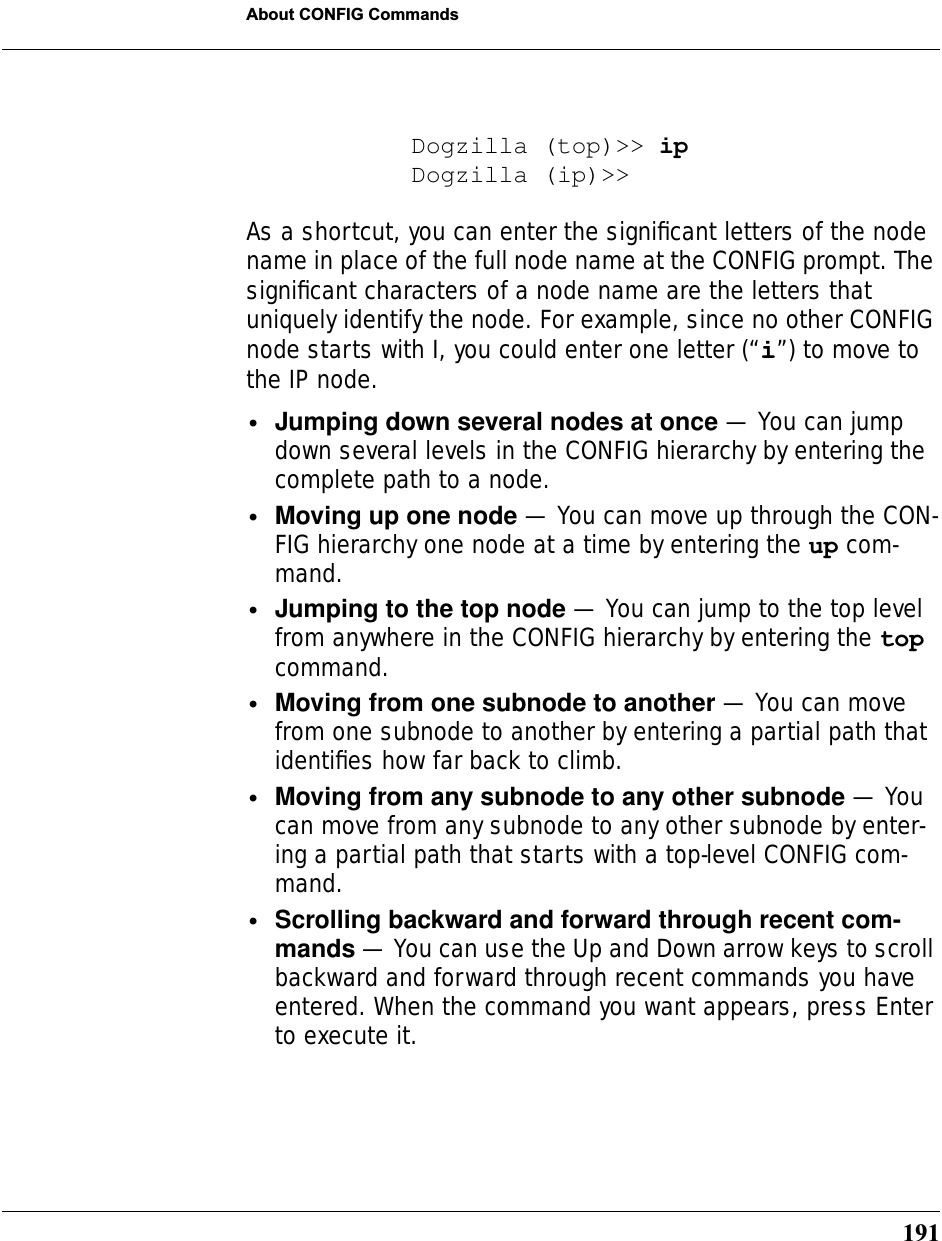
![194Displaying Current Gateway SettingsYou can use the view command to display the current CONFIG settings for your Cayman Gateway. If you enter the view com-mand at the top level of the CONFIG hierarchy, the CLI displays the settings for all enabled functions. If you enter the view com-mand at an intermediate node, you see settings for that node and its subnodes.Step Mode: A CLI Configuration TechniqueThe Cayman Gateway command line interface includes a step mode to automate the process of entering configuration set-tings. When you use the CONFIG step mode, the command line interface prompts you for all required and optional information. You can then enter the configuration values appropriate for your site without having to enter complete CLI commands.When you are in step mode, the command line interface prompts you to enter required and optional settings. If a setting has a default value or a current setting, the command line inter-face displays the default value for the command in parenthe-ses. If a command has a limited number of acceptable values, those values are presented in brackets, with each value sepa-rated by a vertical line. For example, the following CLI step com-mand indicates that the default value is off and that valid entries are limited to on and off.option (off) [on | off]: onYou can accept the default value for a field by pressing the Return key. To use a different value, enter it and press Return.You can enter the CONFIG step mode by entering set from the top node of the CONFIG hierarchy. You can enter step mode for a particular service by entering set service_name. In step-](https://usermanual.wiki/ARRIS/3387W/User-Guide-349176-Page-192.png)
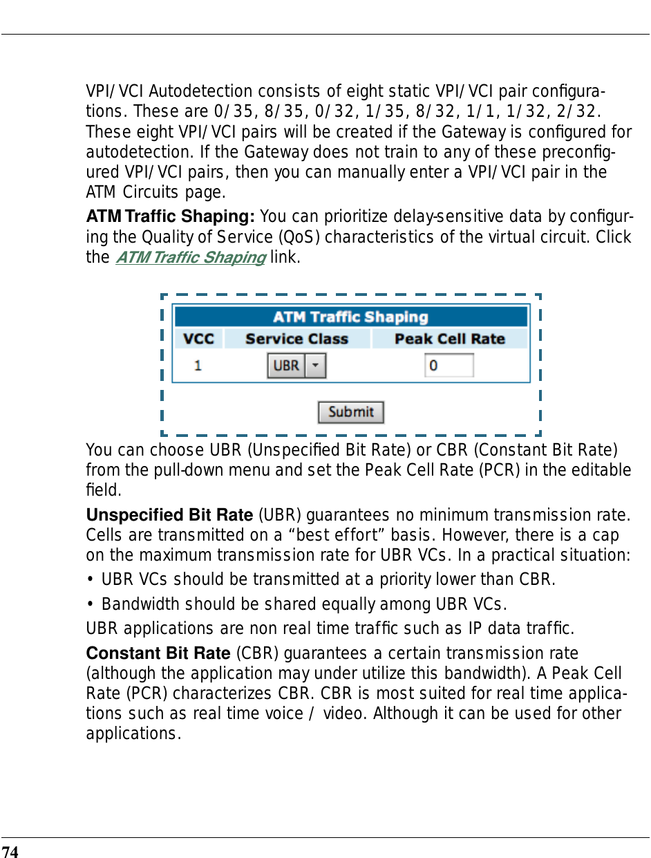
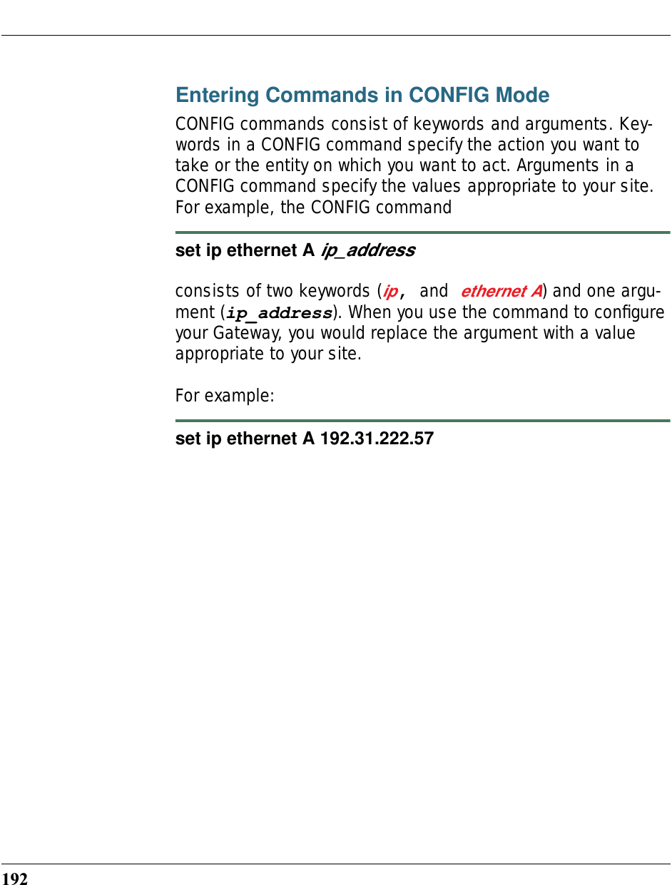
![196CONFIG CommandsThis section describes the keywords and arguments for the var-ious CONFIG commands.DSL CommandsATM Settings. You can use the CLI to set up each ATM virtual circuit. set atm option {on | off } Enables the WAN interface of the Cayman Gateway to be config-ured using the Asynchronous Transfer Mode (ATM) protocol.set atm [vcc n] option {on | off } Selects the virtual circuit for which further parameters are set. Up to eight VCCs are supported; the maximum number is dependent on your Cayman Operating System tier and the capa-bilities that your Service Provider offers.set atm [vcc n] qos service-class { cbr | ubr }Sets the Quality of Service class for the specified virtual circuit – Constant (cbr) or Unspecified (ubr) Bit Rate. •ubr: No configuration is needed for UBR VCs. Leave the default value 0 (maximum line rate).•cbr: One parameter is required for CBR VCs. Enter the Peak Cell Rate that applies to the VC. This value should be between 1 and the line rate. You set this value according to specifications defined by your service provider.](https://usermanual.wiki/ARRIS/3387W/User-Guide-349176-Page-194.png)
![197CONFIG Commandsset atm [vcc n] qos peak-cell-rate { 1 ...n }If QoS class is set to cbr, then specifiy the peak-cell-rate that should apply to the specified virtual circuit. This value should be between 1 and the line rate.set atm [vcc n] vpi { 0 ... 255 } Select the virtual path identifier (vpi) for VCC n.Your Service Provider will indicate the required vpi number.set atm [vcc n] vci { 0 ... 65535 }Select the virtual channel identifier (vci) for VCC n.Your Service Provider will indicate the required vci number.set atm [vccn] encap { ppp-vcmux | ppp-llc | ether-llc | ip-llc | ppoe-vcmux | pppoe-llc }Select the encapsulation mode for VCC n. The options are:Your Service Provider will indicate the required encapsulation mode.ppp-vcmux PPP over ATM, VC-muxedppp-llc PPP over ATM, LLC-SNAPether-llc RFC-1483, bridged Ethernet, LLC-SNAPip-llc RFC-1483, routed IP, LLC-SNAPpppoe-vcmux PPP over Ethernet, VC-muxedpppoe-llc PPP over Ethernet, LLC-SNAP](https://usermanual.wiki/ARRIS/3387W/User-Guide-349176-Page-195.png)
![198set atm [vccn] pppoe-sessions { 1 ... 8 }Select the number of PPPoE sessions to be configured for VCC 1, up to a total of eight. The total number of pppoe-ses-sions and PPPoE VCCs configured must be less than or equal to eight. Bridging SettingsBridging lets the Cayman Gateway use MAC (Ethernet hard-ware) addresses to forward non-TCP/IP traffic from one network to another. When bridging is enabled, the Cayman Gateway maintains a table of up to 512 MAC addresses. Entries that are not used within 30 seconds are dropped. If the bridging table fills up, the oldest table entries are dropped to make room for new entries. Virtual circuits that use IP framing cannot be bridged.☛ NOTE:For bridging in the 3341 (or any model with a USB port), you cannot set the bridge option off, or bridge ethernet option off; these are on by default because of the USB port.Common Commandsset bridge option {on | off }Enables or disables bridging services in the Cayman Gateway. You must enable bridging services within the Cayman Gateway before you can enable bridging for a specific interface.](https://usermanual.wiki/ARRIS/3387W/User-Guide-349176-Page-196.png)
![200sequence of up to 253 IP addresses within a subnet, beginning with the specified address for dynamic assignment. set dhcp end-address ip_address If you selected server, specifies the last address in the DHCP address range.set dhcp lease-time lease-time If you selected server, specifies the default length for DHCP leases issued by the Cayman Gateway. Enter lease time in dd:hh:mm:ss (day/hour/minute/second) format.DMT Settings DSL Commandsset dmt type [ lite | dmt | ansi | multi ] Selects the type of Discrete Multitone (DMT) asynchronous digi-tal subscriber line (ADSL) protocol to use for the WAN interface.☛ NOTE:dmt type is not supported for Annex B (335x) plat-forms.set dmt autoConfig [ off | on ]Enables support for automatic VPI/VCI detection and configura-tion. When set to on (the default), a pre-defined list of VPI/VCI pairs are searched to find a valid configuration for your ADSL](https://usermanual.wiki/ARRIS/3387W/User-Guide-349176-Page-198.png)
 This command configures the wir-ing mode setting for your ADSL line. Selecting auto (the default) causes the Gateway to detect which pair of wires (inner or outer pair) are in use on your phone line. Specifying tip_ring forces the inner pair to be used; and A_A1 the outer pair.Domain Name System SettingsDomain Name System (DNS) is an information service for TCP/IP networks that uses a hierarchical naming system to identify network domains and the hosts associated with them. You can identify a primary DNS server and one secondary server.Common Commandsset dns domain-name domain-name Specifies the default domain name for your network. When an application needs to resolve a host name, it appends the default domain name to the host name and asks the DNS server if it has an address for the “fully qualified host name.” set dns primary-address ip_address Specifies the IP address of the primary DNS name server.](https://usermanual.wiki/ARRIS/3387W/User-Guide-349176-Page-199.png)
![202set dns secondary-address ip_addressSpecifies the IP address of the secondary DNS name server. Enter 0.0.0.0 if your network does not have a secondary DNS name server. IP SettingsYou can use the command line interface to specify whether TCP/IP is enabled, identify a default Gateway, and to enter TCP/IP settings for the Cayman Gateway LAN and WAN ports.☛ NOTE:For the DSL platform you must identify the virtual PPP interface [vccn], a number from 1 to 8.Common Settingsset ip option { on | off }Enables or disables TCP/IP services in the Cayman Gateway. You must enable TCP/IP services before you can enter other TCP/IP settings for the Cayman Gateway. If you turn off TCP/IP services and save the new configuration, the Cayman Gateway clears its TCP/IP settings.](https://usermanual.wiki/ARRIS/3387W/User-Guide-349176-Page-200.png)
![207CONFIG Commandstables to other routers on your network. RIP Version 2 (RIP-2) is an extension of the original Routing Information Protocol (RIP-1) that expands the amount of useful information in the RIP pack-ets. While RIP-1 and RIP-2 share the same basic algorithms, RIP-2 supports several additional features, including inclusion of subnet masks in RIP packets and implementation of multi-casting instead of broadcasting (which reduces the load on hosts which do not support routing protocols. RIP-2 with MD5 authentication is an extension of RIP-2 that increases security by requiring an authentication key when routes are advertised.If you specify v2-MD5, you must also specify a rip-send-key. Keys are ASCII strings with a maximum of 31 characters, and must match the other router(s) keys for proper operation of MD5 support.Depending on your network needs, you can configure your Cay-man Gateway to support RIP-1, RIP-2, or RIP-2MD5.set ip ethernet [ A | B ] rip-receive { off | v1 | v2 | v1-compat | v2-MD5 }Specifies whether the Cayman Gateway should use Routing Information Protocol (RIP) broadcasts to update its routing tables with information received from other routers on your net-work.If you specify v2-MD5, you must also specify a rip-receive-key. Keys are ASCII strings with a maximum of 31 characters, and must match the other router(s) keys for proper operation of MD5 support.](https://usermanual.wiki/ARRIS/3387W/User-Guide-349176-Page-205.png)
![208Default IP Gateway Settingsset ip gateway option { on | off }Specifies whether the Cayman Gateway should send packets to a default Gateway if it does not know how to reach the destina-tion host.set ip gateway interface { ip-address | ppp-vccn }Specifies how the Cayman Gateway should route information to the default Gateway. If you select ip-address, you must enter the IP address of a host on a local or remote network. If you specify ppp, the Cayman unit uses the default gateway being used by the remote PPP peer.IP-over-PPP Settings. Use the following commands to config-ure settings for routing IP over a virtual PPP interface.☛ NOTE:For a DSL platform you must identify the virtual PPP interface [vccn], a number from vcc1 to vcc8. set ip ip-ppp [vccn] option { on | off }Enables or disables IP routing through the virtual PPP interface. By default, IP routing is turned off. You must enable IP routing before you can enter other IP routing settings for the virtual PPP interface. If you turn off IP routing and save the new configura-tion, the Cayman Gateway clears IP routing settings](https://usermanual.wiki/ARRIS/3387W/User-Guide-349176-Page-206.png)
![209CONFIG Commandsset ip ip-ppp [vccn] address ip_addressAssigns an IP address to the virtual PPP interface. If you spec-ify an IP address other than 0.0.0.0, your Cayman Gateway will not negotiate its IP address with the remote peer. If the remote peer does not accept the IP address specified in the ip_address argument as valid, the link will not come up.The default value for the ip_address argument is 0.0.0.0, which indicates that the virtual PPP interface will use the IP address assigned to it by the remote peer. Note that the remote peer must be configured to supply an IP address to your Cayman Gateway if you enter 0.0.0.0 for the ip_address argument.set ip ip-ppp [vccn] peer-address ip_addressSpecifies the IP address of the peer on the other end of the PPP link. If you specify an IP address other than 0.0.0.0, your Cay-man Gateway will not negotiate the remote peer's IP address. If the remote peer does not accept the address in the ip_address argument as its IP address (typically because it has been configured with another IP address), the link will not come up.The default value for the ip_address argument is 0.0.0.0, which indicates that the virtual PPP interface will accept the IP address returned by the remote peer. If you enter 0.0.0.0, the peer system must be configured to supply this address.set ip ip-ppp [vccn] restriction { admin-disabled | none }Specifies restrictions on the types of traffic the Cayman Gate-way accepts over the PPP virtual circuit. The admin-dis-](https://usermanual.wiki/ARRIS/3387W/User-Guide-349176-Page-207.png)
![210abled argument means that access to the device, via telnet, web and SNMP is disabled. The none argument means that all traffic is accepted. set ip ip-ppp [vccn] addr-mapping { on | off }Specifies whether you want the Cayman Gateway to use net-work address translation (NAT) when communicating with remote routers. Network address translation lets you conceal details of your network from remote routers. By default, address mapping is turned on.set ip ip-ppp [vccn] rip-send { off | v1 | v2 | v1-compat | v2-MD5 }Specifies whether the Cayman Gateway unit should use Routing Information Protocol (RIP) broadcasts to advertise its routing tables to routers on the other side of the PPP link. An extension of the original Routing Information Protocol (RIP-1), RIP Version 2 (RIP-2) expands the amount of useful information in the pack-ets. While RIP-1 and RIP-2 share the same basic algorithms, RIP-2 supports several new features. For example, inclusion of subnet masks in RIP packets and implementation of multicast-ing instead of broadcasting. This last feature reduces the load on hosts which do not support routing protocols. RIP-2 with MD5 authentication is an extension of RIP-2 that increases security by requiring an authentication key when routes are advertised.This command is only available when address mapping for the specified virtual circuit is turned “off”.](https://usermanual.wiki/ARRIS/3387W/User-Guide-349176-Page-208.png)
![211CONFIG Commandsset ip ip-ppp [vccn] rip-receive { off | v1 | v2 | v1-compat | v2-MD5 }Specifies whether the Cayman Gateway should use Routing Information Protocol (RIP) broadcasts to update its routing tables with information received from other routers on the other side of the PPP link.This command is only available when address mapping for the specified virtual circuit is turned “off”.Static ARP Settings. Your Cayman Gateway maintains a dynamic Address Resolution Protocol (ARP) table to map IP addresses to Ethernet (MAC) addresses. Your Cayman Gateway populates this ARP table dynamically, by retrieving IP address/MAC address pairs only when it needs them. Optionally, you can define static ARP entries to map IP addresses to their corre-sponding Ethernet MAC addresses. Unlike dynamic ARP table entries, static ARP table entries do not time out.You can configure as many as 16 static ARP table entries for a Cayman Gateway. Use the following commands to add static ARP entries to the Cayman Gateway static ARP table:set ip static-arp ip-address ip_addressSpecifies the IP address for the static ARP entry. Enter an IP address in the ip_address argument in dotted decimal for-mat. The ip_address argument cannot be 0.0.0.0.set ip static-arp ip-address ip_address hardware-address MAC_addressSpecifies the Ethernet hardware address for the static ARP entry. Enter an Ethernet hardware address in the](https://usermanual.wiki/ARRIS/3387W/User-Guide-349176-Page-209.png)
![212MAC_address argument in nn.nn.nn.nn.nn.nn (hexadecimal) format.IGMP Forwardingset ip igmp-forwarding [ off | on ]Turns IP IGMP forwarding off or on. The default is off.IPsec Passthroughset ip ipsec-passthrough [ off | on ]Turns IPsec client passthrough off or on. The default is on.Static Route SettingsA static route identifies a manually configured pathway to a remote network. Unlike dynamic routes, which are acquired and confirmed periodically from other routers, static routes do not time out. Consequently, static routes are useful when working with PPP, since an intermittent PPP link may make maintenance of dynamic routes problematic.You can configure as many as 32 static IP routes for a Cayman Gateway. Use the following commands to maintain static routes to the Cayman Gateway routing table:set ip static-routes destination-network net_addressSpecifies the network address for the static route. Enter a net-work address in the net_address argument in dotted deci-mal format. The net_address argument cannot be 0.0.0.0.](https://usermanual.wiki/ARRIS/3387W/User-Guide-349176-Page-210.png)
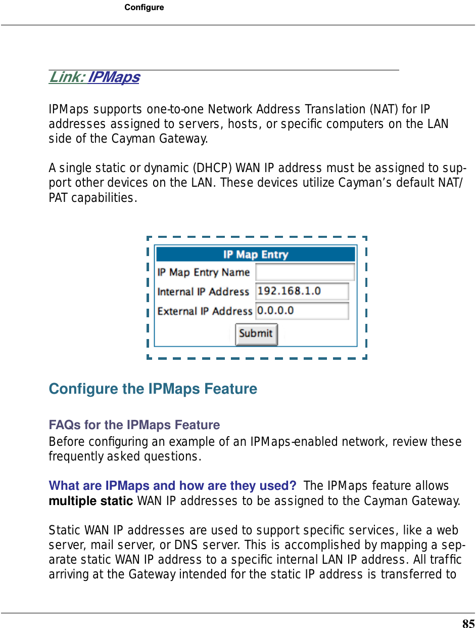
![214•The remote network is more than one router away but the static route should not be replaced by a dynamic route, even if the dynamic route is more efficient. set ip static-routes destination-network net_address rip-advertise [ SplitHorizon | Always | Never ]Specifies whether the gateway should use Routing Information Protocol (RIP) broadcasts to advertise to other routers on your network and which mode to use. The default is SplitHorizon.delete ip static-routes destination-network net_addressDeletes a static route. Deleting a static route removes all infor-mation associated with that route.IPMaps Settingsset ip-maps name <name> internal-ip <ip address>Specifies the name and static ip address of the LAN device to be mapped.set ip-maps name <name> external-ip <ip address>Specifies the name and static ip address of the WAN device to be mapped.Up to 8 mapped static IP addresses are supported.](https://usermanual.wiki/ARRIS/3387W/User-Guide-349176-Page-212.png)
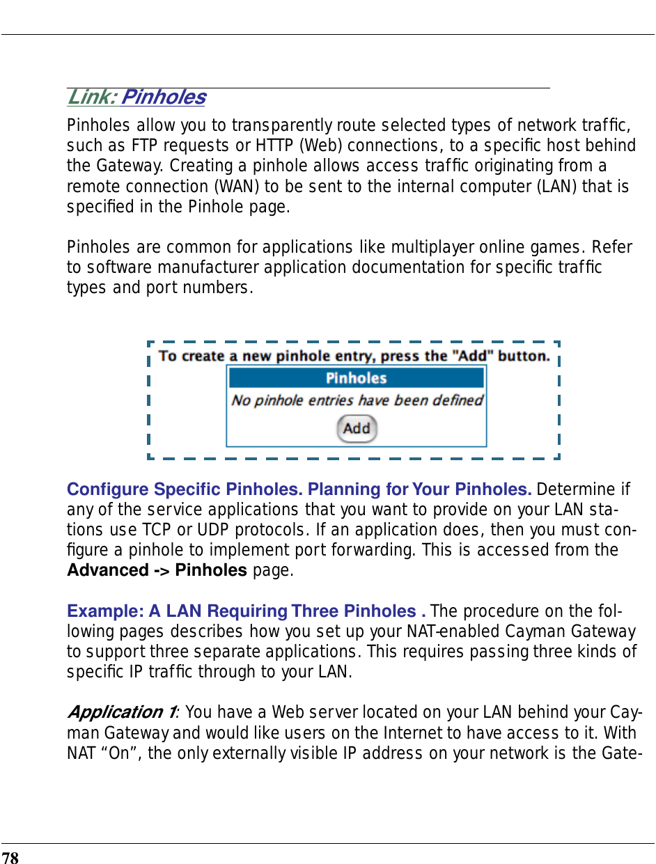
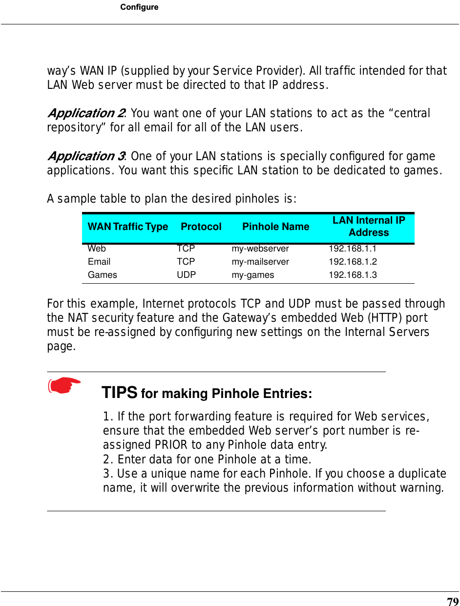
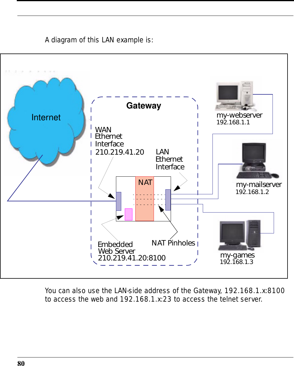
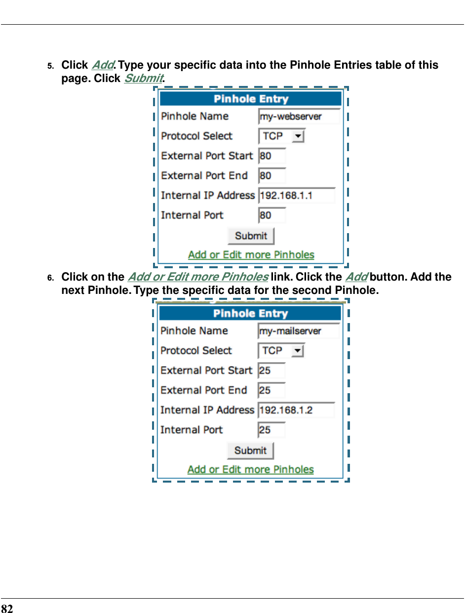
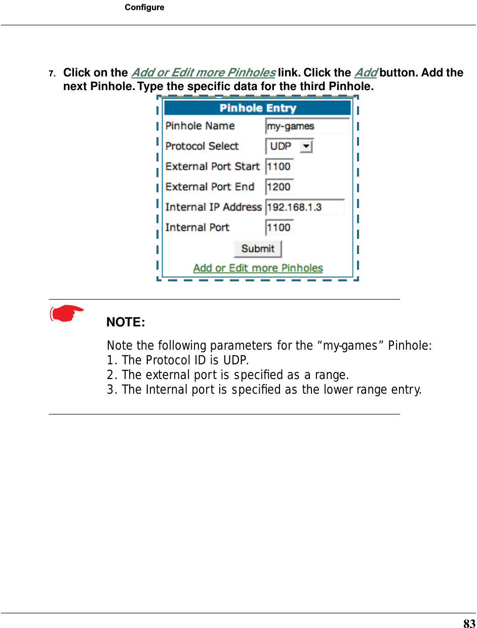
![216Network Address Translation (NAT) Pinhole SettingsNAT pinholes let you pass specific types of network traffic through the NAT interfaces on the Cayman Gateway. NAT pin-holes allow you to route selected types of network traffic, such as FTP requests or HTTP (Web) connections, to a specific host behind the Cayman Gateway transparently.To set up NAT pinholes, you identify the type(s) of traffic you want to redirect by port number, and you specify the internal host to which each specified type of traffic should be directed.The following list identifies protocol type and port number for common TCP/IP protocols:•FTP (TCP 21)•telnet (TCP 23)•SMTP (TCP 25),•TFTP (UDP 69)•SNMP (TCP 161, UDP 161) set pinhole name nameSpecifies the identifier for the entry in the router's pinhole table. You can name pinhole table entries sequentially (1, 2, 3), by port number (21, 80, 23), by protocol, or by some other naming scheme.set pinhole name name protocol-select { tcp | udp }Specifies the type of protocol being redirected.set pinhole name name external-port-start [ 0 - 49151 ]Specifies the first port number in the range being translated.](https://usermanual.wiki/ARRIS/3387W/User-Guide-349176-Page-214.png)
![217CONFIG Commandsset pinhole name name external-port-end [ 0 - 49151 ]Specifies the last port number in the range being translated.set pinhole name name internal-ip internal-ipSpecifies the IP address of the internal host to which traffic of the specified type should be transferred.set pinhole name name internal-port internal-portSpecifies the port number your Cayman Gateway should use when forwarding traffic of the specified type. Under most cir-cumstances, you would use the same number for the external and internal port.PPPoE /PPPoA SettingsYou can use the following commands to configure basic set-tings, port authentication settings, and peer authentication set-tings for PPP interfaces on your Cayman Gateway.Configuring Basic PPP Settings. ☛ NOTE:For the DSL platform you must identify the virtual PPP interface [vccn], a number from 1 to 8.set PPP module [vccn] option { on | off }Enables or disables PPP on the Cayman Gateway.](https://usermanual.wiki/ARRIS/3387W/User-Guide-349176-Page-215.png)
![218set PPP module [vccn] auto-connect { on | off }Supports manual mode required for some vendors. The default on is not normally changed. If auto-connect is disabled (off), you must manually start/stop a ppp connection.set PPP module [vccn] mru integerSpecifies the Maximum Receive Unit (MRU) for the PPP inter-face. The integer argument can be any number between 128 and 1492 for PPPoE; 1500 otherwise.set PPP module [vccn] magic-number { on | off }Enables or disables LCP magic number negotiation.set PPP module [vccn] protocol-compression { on | off }Specifies whether you want the Cayman Gateway to compress the PPP Protocol field when it transmits datagrams over the PPP link.set PPP module [vccn] lcp-echo-requests { on | off }Specifies whether you want your Cayman Gateway to send LCP echo requests. You should turn off LCP echoing if you do not want the Cayman Gateway to drop a PPP link to a nonrespon-sive peer.set PPP module [vccn] failures-max integerSpecifies the maximum number of Configure-NAK messages the PPP module can send without having sent a Configure-ACK mes-sage. The integer argument can be any number between 1 and 20.](https://usermanual.wiki/ARRIS/3387W/User-Guide-349176-Page-216.png)
![219CONFIG Commandsset PPP module [vccn] configure-max integerSpecifies the maximum number of unacknowledged configura-tion requests that your Cayman Gateway will send. The integer argument can be any number between 1 and 10.set PPP module [vccn] terminate-max integerSpecifies the maximum number of unacknowledged termination requests that your Cayman Gateway will send before terminat-ing the PPP link. The integer argument can be any number between 1 and 10. set PPP module [vccn] restart-timer integerSpecifies the number of seconds the Cayman Gateway should wait before retransmitting a configuration or termination request. The integer argument can be any number between 1 and 30.set PPP module [vccn] connection-type { instant-on | always-on }Specifies whether a PPP connection is maintained by the Cay-man Gateway when it is unused for extended periods. If you specify always-on, the Cayman Gateway never shuts down the PPP link. If you specify instant-on, the Cayman Gateway shuts down the PPP link after the number of seconds specified in the time-out setting (below) if no traffic is moving over the circuit.set PPP module [vccn] time-out integerIf you specified a connection type of instant-on, specifies the number of seconds, in the range 30 - 3600, with a default](https://usermanual.wiki/ARRIS/3387W/User-Guide-349176-Page-217.png)
![220value of 300, the Cayman Gateway should wait for communica-tion activity before terminating the PPP link.Configuring Port Authentication. You can use the following command to specify how your Cayman Gateway should respond when it receives an authentication request from a remote peer.The settings for port authentication on the local Cayman Gate-way must match the authentication that is expected by the remote peer. For example, if the remote peer requires CHAP authentication and has a name and CHAP secret for the Cay-man Gateway, you must enable CHAP and specify the same name and secret on the Cayman Gateway before the link can be established.set PPP module [vccn] port-authenticationoption [ off | on | pap-only | chap-only ]username:password:Specifying on turns both PAP and CHAP on, or you can select PAP or CHAP. Specify the username and password when port authentication is turned on (both CHAP and PAP, CHAP or PAP.)The username argument is 1- 255 alphanumeric characters. The information you enter must match the username configured in the PPP peer's authentication database. The password argument is 1-32 alphanumeric characters. The information you enter must match the password used by the PPP peer.Authentication must be enabled before you can enter other information.](https://usermanual.wiki/ARRIS/3387W/User-Guide-349176-Page-218.png)
![221CONFIG CommandsEthernet Port Settingsset ethernet ethernet A mode { auto | 100M-full | 100M-half | 10M-full | 10M-half }Allows mode setting for the ethernet port. Only supported on units without a LAN switch, or dual ethernet products (338x). In the dual ethernet case, “ethernet B” would be specified for the WAN port. The default is auto.Command Line Interface Preference SettingsYou can set command line interface preferences to customize your environment. set preference verbose { on | off }set define verbose { on | off }Specifies whether you want command help and prompting infor-mation displayed. By default, the command line interface ver-bose preference is turned off. If you turn it on, the command line interface displays help for a node when you navigate to that node.set preference more linesset define more linesSpecifies how many lines of information you want the command line interface to display at one time. The lines argument speci-fies the number of lines you want to see at one time. The range is 1-65535. By default, the command line interface shows you 22 lines of text before displaying the prompt: More …[y|n] ?.](https://usermanual.wiki/ARRIS/3387W/User-Guide-349176-Page-219.png)
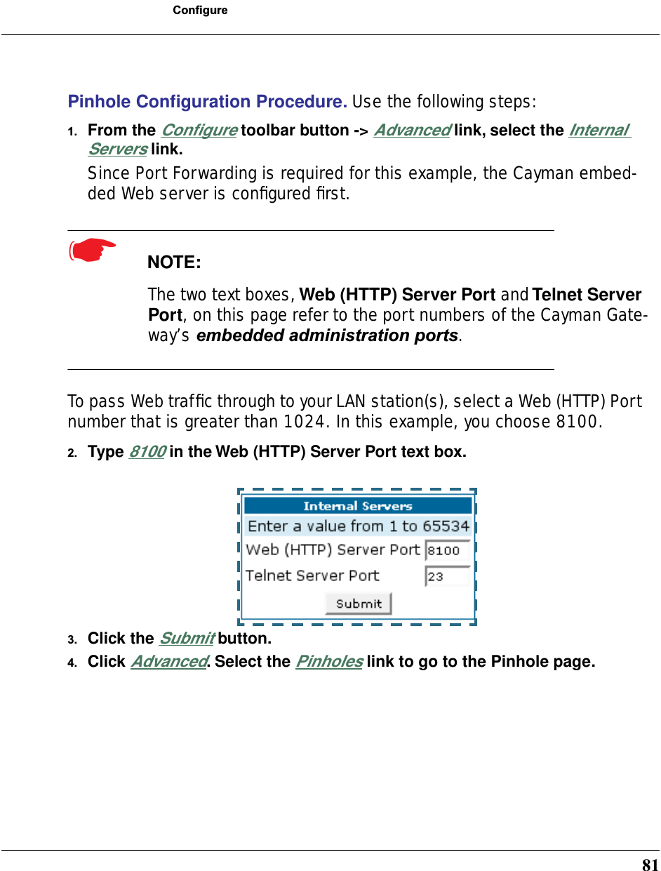
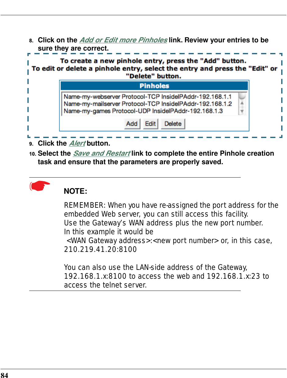
![222If you enter 100 for the lines argument, the command line interface displays information as an uninterrupted stream (which is useful for capturing information to a text file).Port Renumbering SettingsIf you use NAT pinholes to forward HTTP or telnet traffic through your Cayman Gateway to an internal host, you must change the port numbers the Cayman Gateway uses for its own configura-tion traffic. For example, if you set up a NAT pinhole to forward network traffic on Port 80 (HTTP) to another host, you would have to tell the Cayman Gateway to listen for configuration con-nection requests on a port number other than 80, such as 6080.After you have changed the port numbers the Cayman Gateway uses for its configuration traffic, you must use those port num-bers instead of the standard numbers when configuring the Cay-man Gateway. For example, if you move the router's Web service to port “6080” on a box with a DNS name of “super-box”, you would enter the URL http://superbox:6080 in a Web browser to open the Cayman Gateway graphical user interface. Similarly, you would have to configure your telnet application to use the appropriate port when opening a configuration connec-tion to your Cayman Gateway.set servers web-http [ 0 - 65534 ]Specifies the port number for HTTP (web) communication with the Cayman Gateway. Because port numbers in the range 0-1024 are used by other protocols, you should use numbers in the range 2000-65534 when assigning new port numbers to the Cayman Gateway web configuration interface. A setting of 0 (zero) will turn the server off.](https://usermanual.wiki/ARRIS/3387W/User-Guide-349176-Page-220.png)
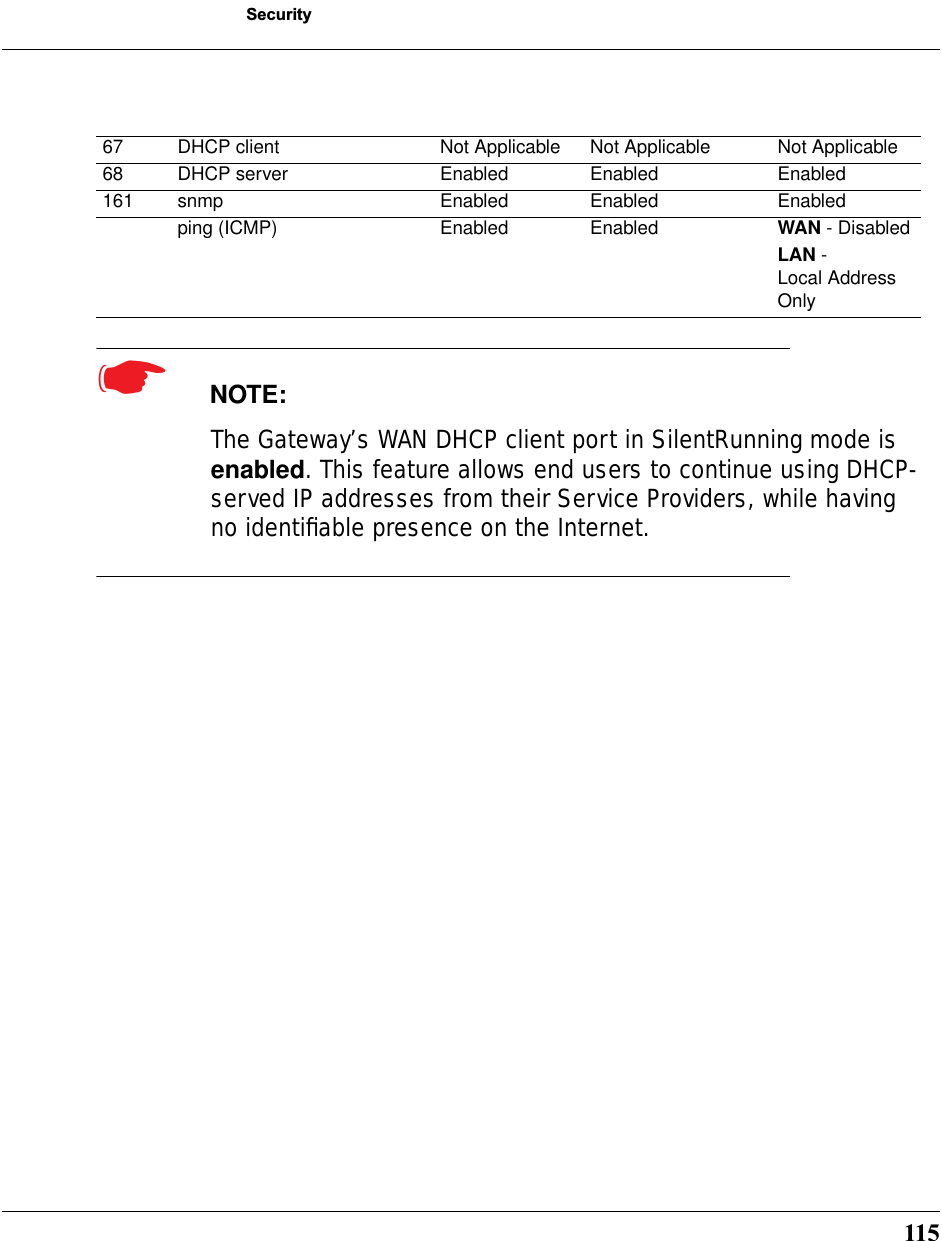
![223CONFIG Commandsset servers telnet-tcp [ 0 - 65534 ]Specifies the port number for telnet (CLI) communication with the Cayman Gateway. Because port numbers in the range 0-1024 are used by other protocols, you should use numbers in the range 2000-65534 when assigning new port numbers to the Cayman Gateway telnet configuration interface. A setting of 0 (zero) will turn the server off.☛ NOTE:You cannot specify a port setting of 0 (zero) for both the web and telnet ports at the same time. This would prevent you from accessing to the Gateway.Security SettingsSecurity settings include the Firewall and IPSec parameters. All of the security functionality is keyed.Firewall Settings (for BreakWater Firewall)set security firewall option [ ClearSailing | SilentRunning | LANdLocked ]The 3 settings for BreakWater are discussed in detail on page page 111.](https://usermanual.wiki/ARRIS/3387W/User-Guide-349176-Page-221.png)
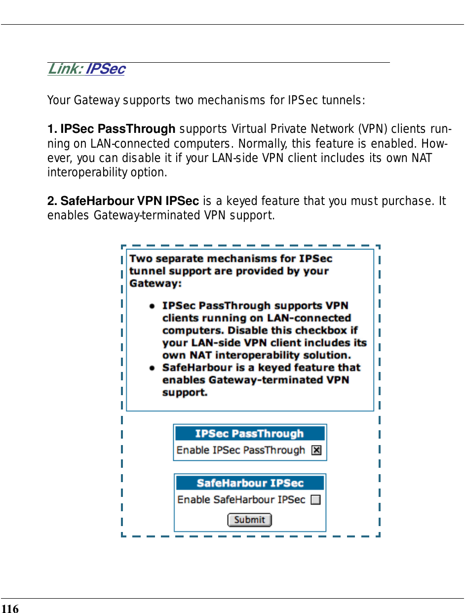
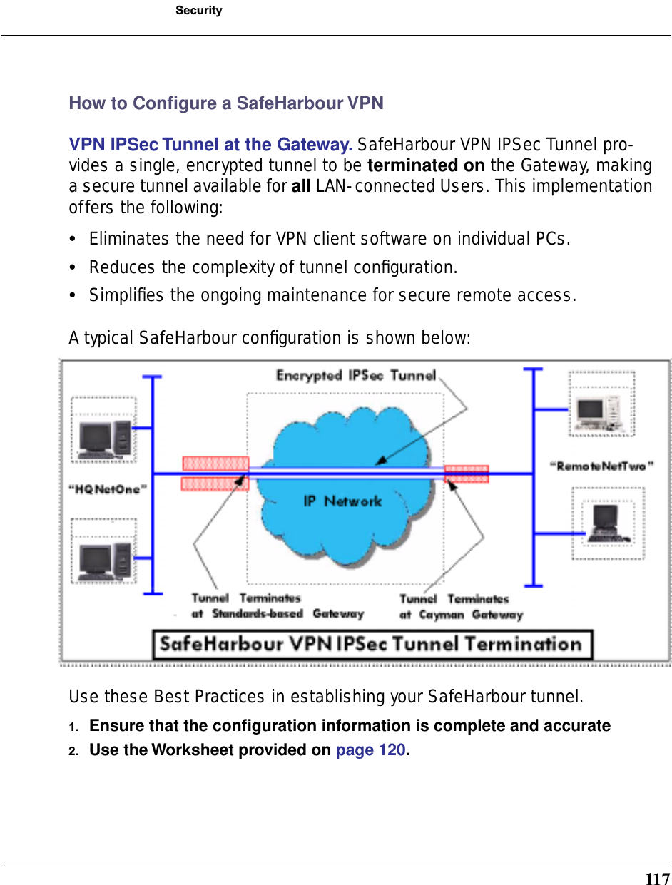
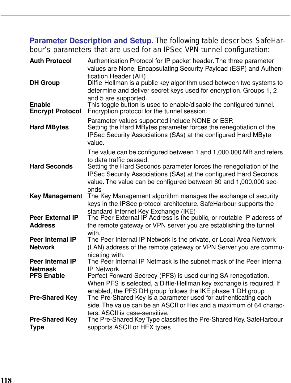
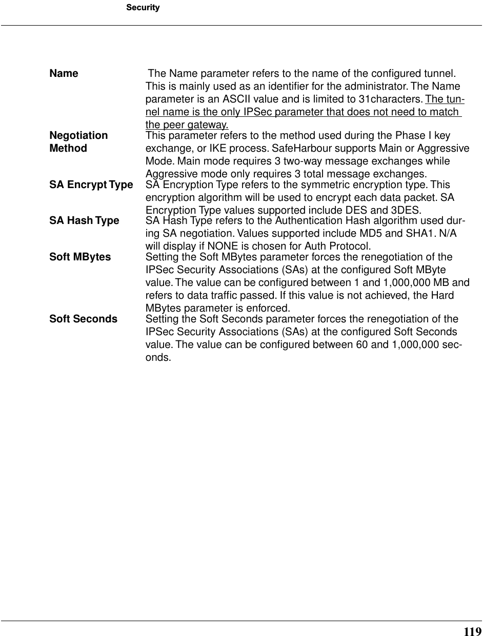
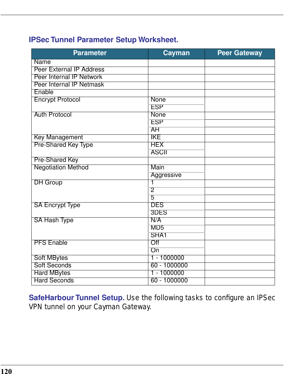
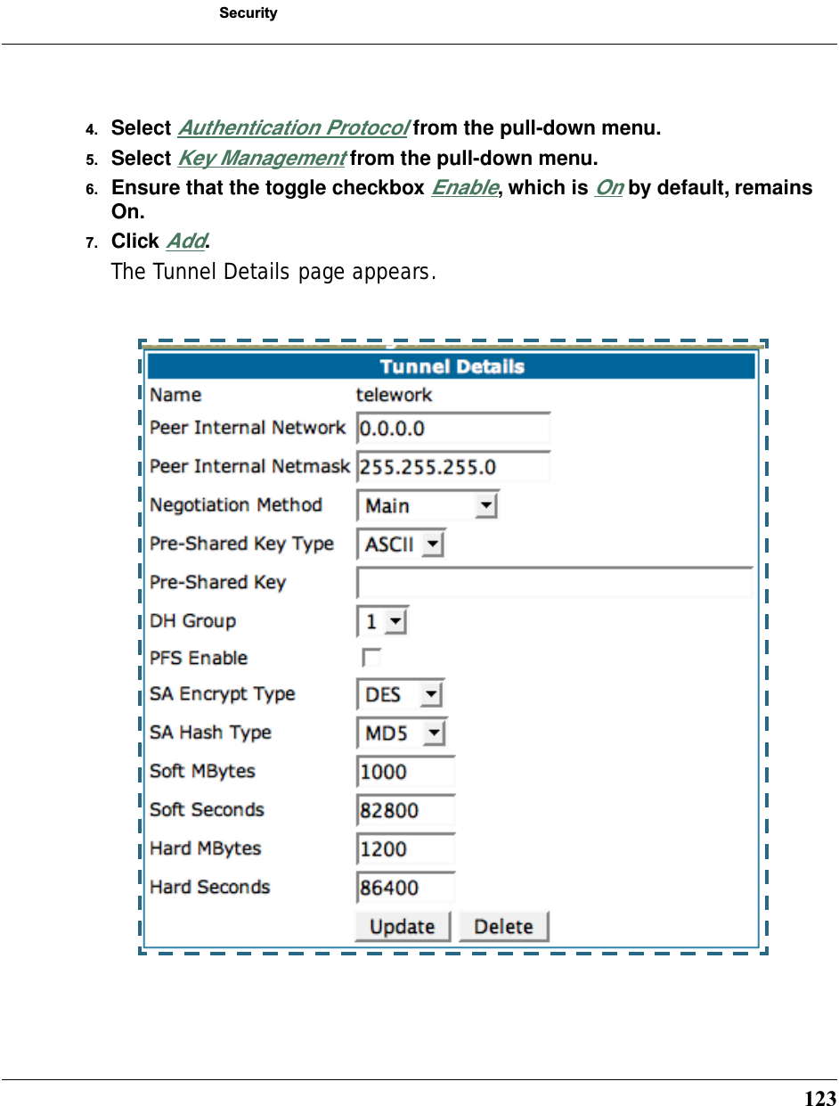
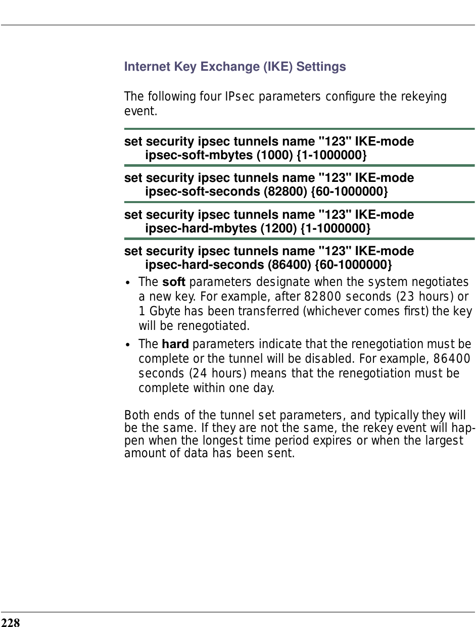
![224IPsec Settingsset security ipsec option [ off | on ]Turns the IPsec option off or on. Default is off. See “IPSec” on page 116 for more information.SafeHarbour IPSec SettingsSafeHarbour VPN is a tunnel between the local network and another geographically dispersed network that is intercon-nected over the Internet. This VPN tunnel provides a secure, cost-effective alternative to dedicated leased lines. Internet Protocol Security (IPsec) is a series of services including encryption, authentication, integrity, and replay protection. Internet Key Exchange (IKE) is the key management protocol of IPsec that establishes keys for encryption and decryption. Because this VPN software implementation is built to these standards, the other side of the tunnel can be either another Cayman unit or another IPsec/IKE based security product. For VPN you can choose to have traffic authenticated, encrypted, or both.When connecting the Cayman unit in a telecommuting scenario, the corporate VPN settings will dictate the settings to be used in the Cayman unit. If a parameter has not been specified from the other end of the tunnel, choose the default unless you fully understand the ramifications of your parameter choice.set security ipsec nat-enable (off) {on | off}This enables Network Address Translation (NAT) over the Safe-Harbour tunnel.](https://usermanual.wiki/ARRIS/3387W/User-Guide-349176-Page-222.png)
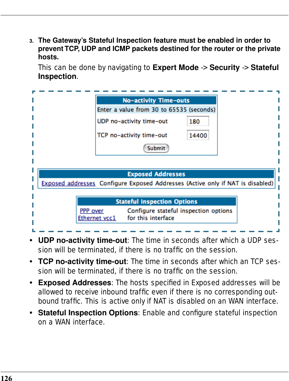
![229CONFIG CommandsStateful InspectionStateful inspection options are accessed by the security state-insp tag.set security state-insp [ ip-ppp | dsl ] vccn option [ off | on ]set security state-insp ethernet [ A | B ] option [ off | on ]Sets the stateful inspection option off or on on the specified interface. This option is disabled by default. Stateful inspection prevents unsolicited inbound access when NAT is disabled.set security state-insp [ ip-ppp | dsl ] vccn default-mapping [ off | on ]set security state-insp ethernet [ A | B ] default-mapping [ off | on ]Sets stateful inspection default mapping to router option off or on on the specified interface.set security state-insp [ ip-ppp | dsl ] vccn tcp-seq-diff [ 0 - 65535 ]set security state-insp ethernet [ A | B ] tcp-seq-diff [ 0 - 65535 ]Sets the acceptable TCP sequence difference on the specified interface. The TCP sequence number difference maximum allowed value is 65535. If the value of tcp-seq-diff is 0, it means that this check is disabled.](https://usermanual.wiki/ARRIS/3387W/User-Guide-349176-Page-227.png)
![230set security state-insp [ ip-ppp | dsl ] vccn deny-fragments [ off | on ]set security state-insp ethernet [ A | B ] deny-fragments [ off | on ]Sets whether fragmented packets are allowed to be received or not on the specified interface.set security state-insp tcp-timeout [ 30 - 65535 ]Sets the stateful inspection TCP timeout interval, in seconds.set security state-insp udp-timeout [ 30 - 65535 ]Sets the stateful inspection UDP timeout interval, in seconds.set security state-insp xposed-addr exposed-address# "n" Allows you to add an entry to the specified list, or, if the list does not exist, creates the list for the stateful inspection fea-ture.Example:set security state-insp xposed-addr exposed-address# (?): 3232 has been added to the xposed-addr list.Sets the exposed list address number.](https://usermanual.wiki/ARRIS/3387W/User-Guide-349176-Page-228.png)
![231CONFIG Commandsset security state-insp xposed-addr exposed-address# "n" start-ip ip_addressSets the exposed list range starting IP address, in dotted quad format.set security state-insp xposed-addr exposed-address# "n" end-ip ip_addressSets the exposed list range ending IP address, in dotted quad format.32 exposed addresses can be created. The range for exposed address numbers are from 1 through 32.set security state-insp xposed-addr exposed-address# "n" protocol [ tcp | udp | both | any ]Sets the protocol for the stateful inspection feature for the exposed address list. Accepted values for protocol are tcp, udp, both, or any.If protocol is not any, you can set port ranges:set security state-insp xposed-addr exposed-address# "n" start-port [ 1 - 65535 ]set security state-insp xposed-addr exposed-address# "n" end-port [ 1 - 65535 ]](https://usermanual.wiki/ARRIS/3387W/User-Guide-349176-Page-229.png)
![235CONFIG CommandsFor security, you cannot use the “step” method to set the sys-tem password.A password can be as many as eight characters. Passwords are case-sensitive. Passwords go into effect immediately. You do not have to restart the Cayman Gateway for the password to take effect. Assigning an administrator or user password to a Cayman Gate-way does not affect communications through the device. set system heartbeat { on | off } protocol [ udp | tcp ] port-client [ 1 - 65535 ]ip-server ip_addressport-server [ 1 - 65535 ]url-server ("server_name")interval (00:00:00:20)contact-email ("string@domain_name")location ("string"):The heartbeat setting is used in conjunction with the configura-tion server to broadcast contact and location information about your Gateway. You can specify the protocol, port, IP-, port-, and URL-server. The interval setting specifies the broadcast update frequency. The contact-email setting is a quote-enclosed text string giving an email address for the Gateway’s administrator. The location setting is a text string allowing you to specify your geographical or other location, such as “Bil-lerica, MA.”](https://usermanual.wiki/ARRIS/3387W/User-Guide-349176-Page-233.png)
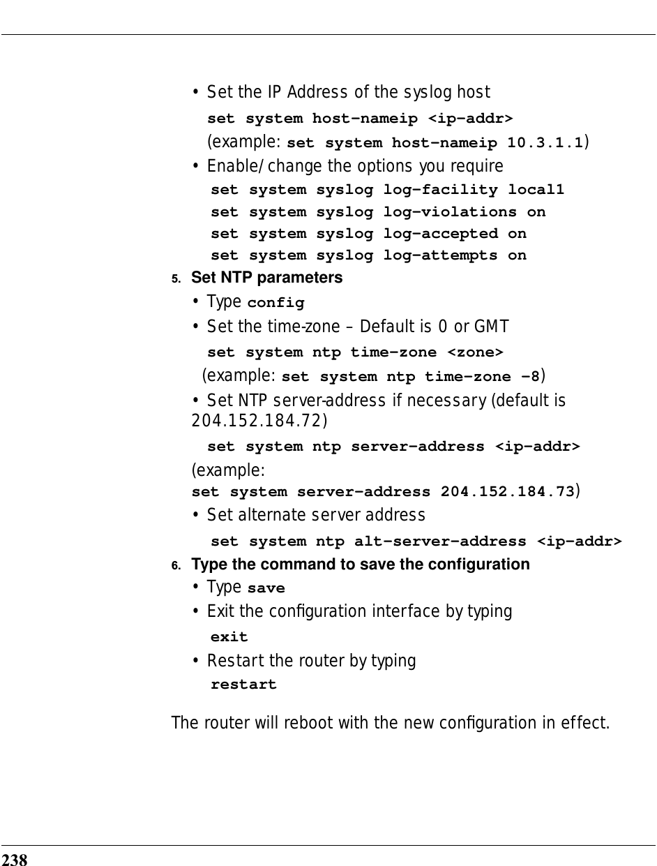
![236set system ntp option [ off | on ]:server-address (204.152.184.72)alt-server-address (""):time-zone [ -12 - 12 ] update-period (60) [ 1 - 65535 ]:Specifies the NTP server address, time zone, and how often the Gateway should check the time from the NTP server. You can leave the NTP server set to 204.152.184.72 and it will use the server addresses known by the Gateway to update the time. NTP time-zone of 0 is GMT time; options are -12 through 12 (+/- 1 hour increments from GMT time). The last setting is for specifying how often, in minutes, the Gateway should update the clock.Syslogset system syslog option [ off | on ]Enables or disables system syslog feature. If syslog option is on, the following commands are available:set system syslog host-nameip [ ip_address | hostname ]Specifies the syslog server’s address either in dotted decimal format or as a DNS name up to 64 characters.set system syslog log-facility [ local0 ... local7 ]Sets the UNIX syslog Facility. Acceptable values are local0 through local7.](https://usermanual.wiki/ARRIS/3387W/User-Guide-349176-Page-234.png)
![237CONFIG Commandsset system syslog log-violations [ off | on ]Specifies whether violations are logged or ignored.set system syslog log-accepted [ off | on ]Specifies whether acceptances are logged or ignored.set system syslog log-attempts [ off | on ]Specifies whether connection attempts are logged or ignored.Default syslog installation procedure1. Access the router through the serial interface (if available) or telnet to the product from the private LAN. DHCP server is enabled on the LAN by default.2. There will be a prompt to set up the administrative password. The default Username is admin and this cannot be changed.3. The product’s stateful inspection feature needs to be enabled in order to prevent TCP, UDP and ICMP packets destined to the router or the private hosts.This can be done by entering the CONFIG interface.• Type config• Type the command to enable stateful inspection set security state-insp eth B option on• Type the command to enable the router to drop fragmented packets set security state-insp eth B deny-fragments on4. Enabling syslog:• Type config• Type the command to enable syslog set system syslog option on](https://usermanual.wiki/ARRIS/3387W/User-Guide-349176-Page-235.png)

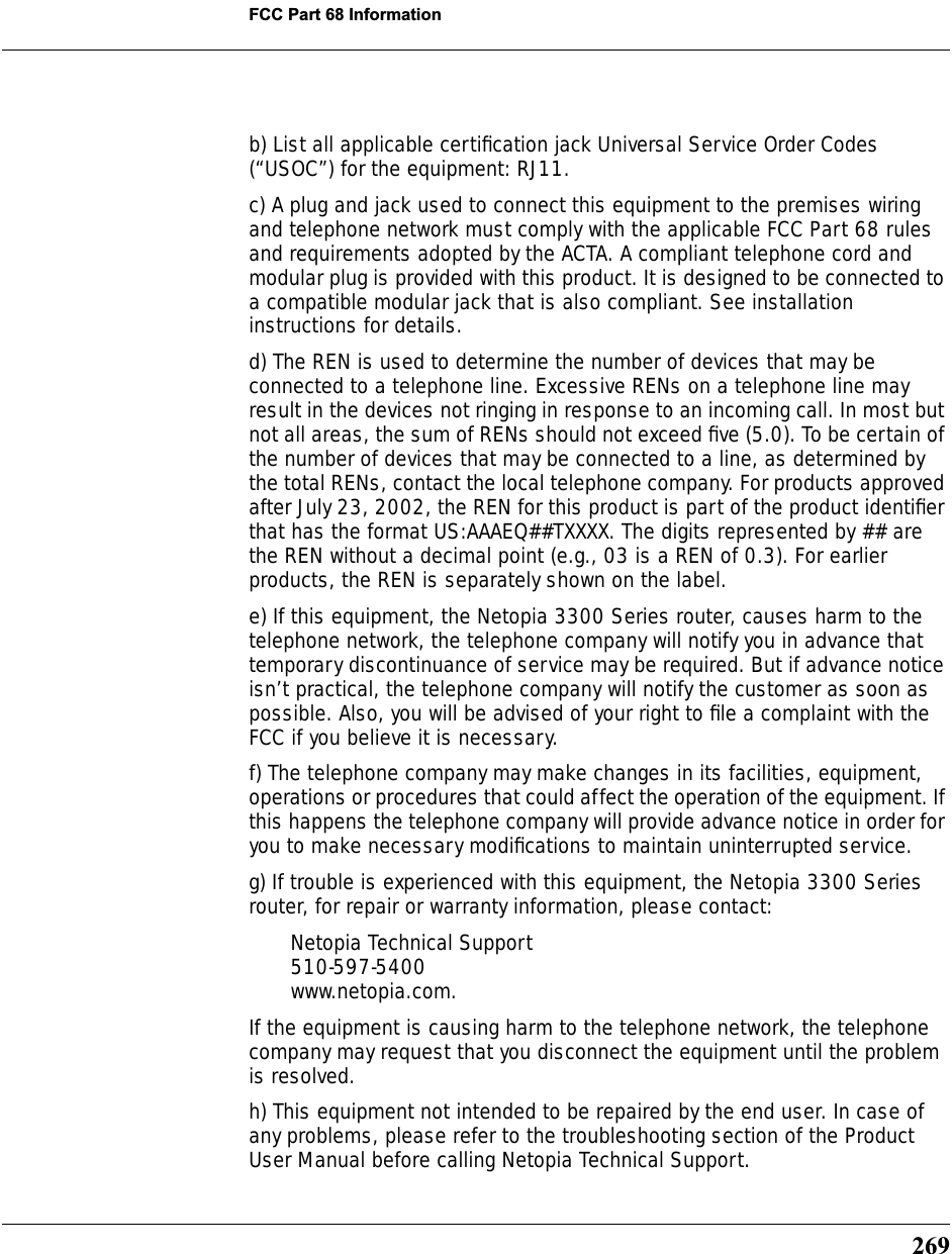
![268FCC Part 68 InformationFCC Requirements1. The Federal Communications Commission (FCC) has established Rules which permit this device to be directly connected to the telephone network. Standardized jacks are used for these connections. This equipment should not be used on party lines or coin phones.2. If this device is malfunctioning, it may also be causing harm to the telephone network; this device should be disconnected until the source of the problem can be determined and until repair has been made. If this is not done, the telephone company may temporarily disconnect service.3. The telephone company may make changes in its technical operations and procedures; if such changes affect the compatibility or use of this device, the telephone company is required to give adequate notice of the changes. You will be advised of your right to file a complaint with the FCC.4. If the telephone company requests information on what equipment is connected to their lines, inform them of:a. The telephone number to which this unit is connected.b. The ringer equivalence number. [0.XB]c. The USOC jack required. [RJ11C]d. The FCC Registration Number. [XXXUSA-XXXXX-XX-E]Items (b) and (d) are indicated on the label. The Ringer Equivalence Number (REN) is used to determine how many devices can be connected to your telephone line. In most areas, the sum of the REN's of all devices on any one line should not exceed five (5.0). If too many devices are attached, they may not ring properly.FCC Statementsa) This equipment complies with Part 68 of the FCC rules and the requirements adopted by the ACTA. On the bottom of this equipment is a label that contains, among other information, a product identifier in the format US:AAAEQ##TXXXX. If requested, this number must be provided to the telephone company.](https://usermanual.wiki/ARRIS/3387W/User-Guide-349176-Page-266.png)