ARRIS 3387W Ethernet to Ethernet Router with 802.11b User Manual Software User Guide V7 2
ARRIS Group, Inc. Ethernet to Ethernet Router with 802.11b Software User Guide V7 2
ARRIS >
Users Guide

Software User Guide
Cayman® Operating System
Version 7.2
July 2003
Cayman® 3300 Series Gateways by Netopia
D
Dr
ra
af
ft
t
D
Do
oc
cu
um
me
en
nt
ta
at
ti
io
on
n
-
--
-
N
No
ot
t
f
fo
or
r
D
Di
is
st
tr
ri
ib
bu
ut
ti
i
o
on
n

2
Disclaimers
Copyright © 2003 Netopia, Inc.
All rights reserved, Printed in the USA.
The information in this document is subject to change without notice. The statements, configurations, technical data, and recom-
mendations in this document are believed to be accurate and reliable, but are presented without express or implied warranty. Users
must take full responsibility for the applications of any products specified in this document.
Portions of this software are subject to the Mozilla Public License Version 1.1. Portions created by Netscape are copyright 1994-2000
Netscape Communications Corporation. You may obtain a copy of the license at http://www.mozilla.org/MPL/. Software distributed
under the License is distributed on an “as is” basis, WITHOUT WARRANTY OF ANY KIND, either express or implied. See the License
for the specific language governing rights and limitations under the License.
Portions of this software copyright 1988, 1991 by Carnegie Mellon University. All rights reserved. Permission to use, copy, modify,
and distribute this software and its documentation for any purpose and without fee is hereby granted, provided that the above copy-
right notice and this permission notice appear in supporting documentation, and that the name of Carnegie Mellon University not
be used in advertising or publicity pertaining to distribution of the software without specific, written prior permission.
CARNEGIE MELLON UNIVERSITY DISCLAIMS ALL WARRANTIES WITH REGARD TO THIS SOFTWARE, INCLUDING ALL IMPLIED WAR-
RANTIES OF MERCHANTABILITY AND FITNESS. IN NO EVENT SHALL CMU BE LIABLE FOR ANY SPECIAL, INDIRECT, OR CONSE-
QUENTIAL DAMAGES OR ANY DAMAGES WHATSOEVER RESULTING FROM LOSS OF USE, DATA, OR PROFITS, WHETHER IN AN
ACTION OF CONTRACT, NEGLIGENCE, OR OTHER TORTIOUS ACTION, ARISING OUT OF OR IN CONNECTION WITH THE USE OR
PERFORMANCE OF THIS SOFTWARE.
The information in this document is proprietary to Netopia, Inc.
Trademarks
Netopia, Cayman, and “Making Broadband Work” are registered trademarks of Netopia, Inc. All rights reserved.
Ethernet is a registered trademark of Xerox Corporation. Microsoft and Windows are registered trademarks of Microsoft Corporation.
All other trademarks are the property of their respective owners. Mention of third-party products is for informational purposes only
and constitutes neither an endorsement nor a recommendation. Netopia assumes no responsibility with regard to the performance
or use of these products.
Statement of Conditions
In the interest of improving internal design, operational function, and /or reliability, Netopia, Inc. reserves the right to make changes
to the products described in this document without notice.
Netopia
, Inc. does not assume any liability that may occur due to the use or application of the product(s) or network con-
figurations described herein.
Netopia, Inc. Part Number: 6161158-00-01d5 v071403

3
Table of Contents
Table of Contents
Disclaimers . . . . . . . . . . . . . . . . . . . . . . . . . . . . . . . . . . . . . . . . . 2
CHAPTER 1
Introduction
. . . . . . . . . . . . . . . . . . . . . . . . . . . . . . . . . 11
About Cayman Documentation . . . . . . . . . . . . . . . . . . . . . . . . 11
Intended Audience . . . . . . . . . . . . . . . . . . . . . . . . . . . . . . . . . . 12
Documentation Conventions . . . . . . . . . . . . . . . . . . . . . . . . . . 13
General
. . . . . . . . . . . . . . . . . . . . . . . . . . . . . . . . . . . . . . . . . . . . . . . . 13
Internal Web Interface
. . . . . . . . . . . . . . . . . . . . . . . . . . . . . . . . . . . . . 13
Command Line Interface
. . . . . . . . . . . . . . . . . . . . . . . . . . . . . . . . . . . 14
Text
. . . . . . . . . . . . . . . . . . . . . . . . . . . . . . . . . . . . . . . . . . . . . . . . . . . 14
Organization . . . . . . . . . . . . . . . . . . . . . . . . . . . . . . . . . . . . . . . 15
Overview of Major Capabilities . . . . . . . . . . . . . . . . . . . . . . . . . 16
A Word About Example Screens . . . . . . . . . . . . . . . . . . . . . . . 17
CHAPTER 2
Basic Mode Setup
. . . . . . . . . . . . . . . . . . . . . . . . . . . . . 19
Important Safety Instructions . . . . . . . . . . . . . . . . . . . . . . . . . . 20
POWER SUPPLY INSTALLATION
. . . . . . . . . . . . . . . . . . . . . . . . . . . 20
TELECOMMUNICATION INSTALLATION
. . . . . . . . . . . . . . . . . . . . . . 20
Set up the Cayman Gateway . . . . . . . . . . . . . . . . . . . . . . . . . . 21
Configure the Cayman Gateway . . . . . . . . . . . . . . . . . . . . . . . 23
Cayman Gateway Status Indicator Lights . . . . . . . . . . . . . . . . 26
Home Page - Basic Mode . . . . . . . . . . . . . . . . . . . . . . . . . . . . 27
Manage My Account . . . . . . . . . . . . . . . . . . . . . . . . . . . . . . . . . . . . . . 29
Status Details . . . . . . . . . . . . . . . . . . . . . . . . . . . . . . . . . . . . . . . . . . . 30
Enable Remote Management . . . . . . . . . . . . . . . . . . . . . . . . . . . . . . . 31
Expert Mode . . . . . . . . . . . . . . . . . . . . . . . . . . . . . . . . . . . . . . . . . . . . 32
Update Firmware. . . . . . . . . . . . . . . . . . . . . . . . . . . . . . . . . . . . . . . . . 33
Factory Reset . . . . . . . . . . . . . . . . . . . . . . . . . . . . . . . . . . . . . . . . . . . 34

Table of Contents
4
CHAPTER 3
Expert Mode
. . . . . . . . . . . . . . . . . . . . . . . . . . . . . . . . . . 35
Overview of Major Capabilities . . . . . . . . . . . . . . . . . . . . . . . . . 35
Wide Area Network Termination
. . . . . . . . . . . . . . . . . . . . . . . . . . . . . . 36
PPPoE/PPPoA (Point-to-Point Protocol over Ethernet/ATM) . . . . 36
Instant-On PPP . . . . . . . . . . . . . . . . . . . . . . . . . . . . . . . . . . . . . . . 37
Simplified Local Area Network Setup
. . . . . . . . . . . . . . . . . . . . . . . . . . 38
DHCP (Dynamic Host Configuration Protocol) Server . . . . . . . . . 38
DNS Proxy . . . . . . . . . . . . . . . . . . . . . . . . . . . . . . . . . . . . . . . . . . 38
Management
. . . . . . . . . . . . . . . . . . . . . . . . . . . . . . . . . . . . . . . . . . . . . 39
Embedded Web Server . . . . . . . . . . . . . . . . . . . . . . . . . . . . . . . . 39
Diagnostics . . . . . . . . . . . . . . . . . . . . . . . . . . . . . . . . . . . . . . . . . . 39
Security
. . . . . . . . . . . . . . . . . . . . . . . . . . . . . . . . . . . . . . . . . . . . . . . . . 40
Remote Access Control . . . . . . . . . . . . . . . . . . . . . . . . . . . . . . . . 40
Password Protection . . . . . . . . . . . . . . . . . . . . . . . . . . . . . . . . . . . 40
Network Address Translation (NAT) . . . . . . . . . . . . . . . . . . . . . . . 40
Cayman Advanced Features for NAT . . . . . . . . . . . . . . . . . . . . . . 42
Internal Servers . . . . . . . . . . . . . . . . . . . . . . . . . . . . . . . . . . . . . . 43
Pinholes . . . . . . . . . . . . . . . . . . . . . . . . . . . . . . . . . . . . . . . . . . . . 43
Default Server . . . . . . . . . . . . . . . . . . . . . . . . . . . . . . . . . . . . . . . . 44
Combination NAT Bypass Configuration . . . . . . . . . . . . . . . . . . . 44
IP-Passthrough . . . . . . . . . . . . . . . . . . . . . . . . . . . . . . . . . . . . . . . 44
VPN IPSec Pass Through . . . . . . . . . . . . . . . . . . . . . . . . . . . . . . 44
VPN IPSec Tunnel Termination . . . . . . . . . . . . . . . . . . . . . . . . . . 46
Stateful Inspection Firewall . . . . . . . . . . . . . . . . . . . . . . . . . . . . . . 46
Access the Web Interface . . . . . . . . . . . . . . . . . . . . . . . . . . . . . 47
Open the Web Connection
. . . . . . . . . . . . . . . . . . . . . . . . . . . . . . . . . . 47
Home Page - Expert Mode
. . . . . . . . . . . . . . . . . . . . . . . . . . . . . . . . . . 49
Home Page - Information
. . . . . . . . . . . . . . . . . . . . . . . . . . . . . . . . . . . 50
Toolbar . . . . . . . . . . . . . . . . . . . . . . . . . . . . . . . . . . . . . . . . . . . 51
Navigating the Web Interface . . . . . . . . . . . . . . . . . . . . . . . . . . 52
Breadcrumb Trail . . . . . . . . . . . . . . . . . . . . . . . . . . . . . . . . . . . . . . . . . 52
Restart . . . . . . . . . . . . . . . . . . . . . . . . . . . . . . . . . . . . . . . . . . . 53
Alert Symbol . . . . . . . . . . . . . . . . . . . . . . . . . . . . . . . . . . . . . . . . . . . . . 54
Help . . . . . . . . . . . . . . . . . . . . . . . . . . . . . . . . . . . . . . . . . . . . . 55
Configure . . . . . . . . . . . . . . . . . . . . . . . . . . . . . . . . . . . . . . . . . 56
Quickstart
. . . . . . . . . . . . . . . . . . . . . . . . . . . . . . . . . . . . . . . . . . . . . . . 56
How to Use the Quickstart Page . . . . . . . . . . . . . . . . . . . . . . . . . 56
Configure -> Quickstart. . . . . . . . . . . . . . . . . . . . . . . . . . . . . . . . . . . . . 56
Setup Your Gateway using a PPP Connection . . . . . . . . . . . . . . 56
LAN
. . . . . . . . . . . . . . . . . . . . . . . . . . . . . . . . . . . . . . . . . . . . . . . . . . . . 58
Configure -> LAN . . . . . . . . . . . . . . . . . . . . . . . . . . . . . . . . . . . . . . . . . 58

5
Table of Contents
About Closed System Mode........................................................ 63
WAN
. . . . . . . . . . . . . . . . . . . . . . . . . . . . . . . . . . . . . . . . . . . . . . . . . . 72
Configure -> WAN . . . . . . . . . . . . . . . . . . . . . . . . . . . . . . . . . . . . . . . . 72
Advanced. . . . . . . . . . . . . . . . . . . . . . . . . . . . . . . . . . . . . . . . . . . . . . . 76
IP Static Routes. . . . . . . . . . . . . . . . . . . . . . . . . . . . . . . . . . . . . . . . . . 76
IP Static ARP. . . . . . . . . . . . . . . . . . . . . . . . . . . . . . . . . . . . . . . . . . . . 77
Pinholes. . . . . . . . . . . . . . . . . . . . . . . . . . . . . . . . . . . . . . . . . . . . . . . . 78
Configure Specific Pinholes . . . . . . . . . . . . . . . . . . . . . . . . . . . . 78
Planning for Your Pinholes . . . . . . . . . . . . . . . . . . . . . . . . . . . . . 78
Example: A LAN Requiring Three Pinholes . . . . . . . . . . . . . . . . 78
Pinhole Configuration Procedure . . . . . . . . . . . . . . . . . . . . . . . . 81
IPMaps . . . . . . . . . . . . . . . . . . . . . . . . . . . . . . . . . . . . . . . . . . . . . . . . 85
Configure the IPMaps Feature . . . . . . . . . . . . . . . . . . . . . . . . . . . . . . 85
FAQs for the IPMaps Feature ..................................................... 85
What are IPMaps and how are they used? . . . . . . . . . . . . . . . . . 85
What types of servers are supported by IPMaps? . . . . . . . . . . . 86
Can I use IPMaps with my PPPoE or PPPoA connection? . . . . . 86
Will IPMaps allow IP addresses from different subnets to be assigned to my
Gateway? . . . . . . . . . . . . . . . . . . . . . . . . . . . . . . . . . . . . . . . . . . 86
IPMaps Block Diagram................................................................ 87
Default Server . . . . . . . . . . . . . . . . . . . . . . . . . . . . . . . . . . . . . . . . . . . 88
Configure a Default Server . . . . . . . . . . . . . . . . . . . . . . . . . . . . . 88
Typical Network Diagram . . . . . . . . . . . . . . . . . . . . . . . . . . . . . . 90
NAT Combination Application . . . . . . . . . . . . . . . . . . . . . . . . . . . 91
IP-Passthrough . . . . . . . . . . . . . . . . . . . . . . . . . . . . . . . . . . . . . . 91
A restriction . . . . . . . . . . . . . . . . . . . . . . . . . . . . . . . . . . . . . . . . . 92
DNS. . . . . . . . . . . . . . . . . . . . . . . . . . . . . . . . . . . . . . . . . . . . . . . . . . . 93
DHCP Server. . . . . . . . . . . . . . . . . . . . . . . . . . . . . . . . . . . . . . . . . . . . 93
SNMP . . . . . . . . . . . . . . . . . . . . . . . . . . . . . . . . . . . . . . . . . . . . . . . . . 94
Advanced -> Ethernet Bridge . . . . . . . . . . . . . . . . . . . . . . . . . . . . . . . 96
Configuring for Bridge Mode . . . . . . . . . . . . . . . . . . . . . . . . . . . . . . . . 97
System. . . . . . . . . . . . . . . . . . . . . . . . . . . . . . . . . . . . . . . . . . . . . . . . 100
Syslog Parameters . . . . . . . . . . . . . . . . . . . . . . . . . . . . . . . . . . . . . . 101
Internal Servers . . . . . . . . . . . . . . . . . . . . . . . . . . . . . . . . . . . . . . . . . 103
Software Hosting . . . . . . . . . . . . . . . . . . . . . . . . . . . . . . . . . . . . . . . . 104
List of Supported Games and Software ...................................... 105
Rename a User(PC) . . . . . . . . . . . . . . . . . . . . . . . . . . . . . . . . . . . . . 105
Clear Options. . . . . . . . . . . . . . . . . . . . . . . . . . . . . . . . . . . . . . . . . . . 106
Security . . . . . . . . . . . . . . . . . . . . . . . . . . . . . . . . . . . . . . . . . 108
Passwords. . . . . . . . . . . . . . . . . . . . . . . . . . . . . . . . . . . . . . . . . . . . . 109
Create and Change Passwords . . . . . . . . . . . . . . . . . . . . . . . . 109
Firewall . . . . . . . . . . . . . . . . . . . . . . . . . . . . . . . . . . . . . . . . . . . . . . . 111
Use a Cayman Firewall ............................................................... 111
BreakWater Basic Firewall . . . . . . . . . . . . . . . . . . . . . . . . . . . . 111

Table of Contents
6
Configuring for a BreakWater Setting.......................................... 112
TIPS for making your BreakWater Basic Firewall Selection ....... 113
Basic Firewall Background .......................................................... 113
IPSec . . . . . . . . . . . . . . . . . . . . . . . . . . . . . . . . . . . . . . . . . . . . . . . . . 116
How to Configure a SafeHarbour VPN........................................ 117
VPN IPSec Tunnel at the Gateway . . . . . . . . . . . . . . . . . . . . . . 117
Parameter Description and Setup . . . . . . . . . . . . . . . . . . . . . . . 118
IPSec Tunnel Parameter Setup Worksheet . . . . . . . . . . . . . . . . 120
SafeHarbour Tunnel Setup . . . . . . . . . . . . . . . . . . . . . . . . . . . . . 120
Task 1: Ensure that you have SafeHarbour VPN enabled. ......... 121
Task2: Complete Parameter Setup Worksheet........................... 121
Task 3: Enable IPSec.................................................................. 121
Task 4: Make the IPSec Tunnel Entries ...................................... 122
Task 5: Make the Tunnel Details entries ..................................... 124
Stateful Inspection . . . . . . . . . . . . . . . . . . . . . . . . . . . . . . . . . . . . . . . 125
Stateful Inspection Firewall installation procedure . . . . . . . . . . . . . . . 125
Exposed Addresses . . . . . . . . . . . . . . . . . . . . . . . . . . . . . . . . . . . . . . 127
Stateful Inspection Options. . . . . . . . . . . . . . . . . . . . . . . . . . . . . . . . . 130
Open Ports in Default Stateful Inspection Installation . . . . . . . . . . . . 131
Log Event Dispositions . . . . . . . . . . . . . . . . . . . . . . . . . . . . . . . . . . . . 131
Security Log . . . . . . . . . . . . . . . . . . . . . . . . . . . . . . . . . . . . . . . . . . . . 132
Using the Security Monitoring Log .............................................. 133
Timestamp Background............................................................... 135
Install . . . . . . . . . . . . . . . . . . . . . . . . . . . . . . . . . . . . . . . . . . . 136
Install Software . . . . . . . . . . . . . . . . . . . . . . . . . . . . . . . . . . . . . . . . . . 137
Updating Your Gateway’s CaymanOS Version . . . . . . . . . . . . . 137
Task 1: Required Files . . . . . . . . . . . . . . . . . . . . . . . . . . . . . . . . . . . . 138
Task 2: CaymanOS Image File. . . . . . . . . . . . . . . . . . . . . . . . . . . . . . 138
Install Keys . . . . . . . . . . . . . . . . . . . . . . . . . . . . . . . . . . . . . . . . . . . . . 142
Use Cayman Software Feature Keys . . . . . . . . . . . . . . . . . . . . . . . . . 142
Obtaining Software Feature Keys .............................................. 142
Procedure - Install a New Feature Key File................................. 142
To check your installed features:................................................. 144
CHAPTER 4
Basic Troubleshooting
. . . . . . . . . . . . . . . . . . . . . . . . . 147
Status Indicator Lights . . . . . . . . . . . . . . . . . . . . . . . . . . . . . . 148
Factory Reset Switch . . . . . . . . . . . . . . . . . . . . . . . . . . . . . . . 155

7
Table of Contents
CHAPTER 5
Advanced Troubleshooting
. . . . . . . . . . . . . . . . . . . . . 157
Home Page
. . . . . . . . . . . . . . . . . . . . . . . . . . . . . . . . . . . . . . . . . . . . 158
Expert Mode
. . . . . . . . . . . . . . . . . . . . . . . . . . . . . . . . . . . . . . . . . . . 161
System Status ............................................................................. 161
Ports: Ethernet. . . . . . . . . . . . . . . . . . . . . . . . . . . . . . . . . . . . . . . . . . 162
Ports: DSL . . . . . . . . . . . . . . . . . . . . . . . . . . . . . . . . . . . . . . . . . . . . . 163
DSL: Circuit Configuration. . . . . . . . . . . . . . . . . . . . . . . . . . . . . . . . . 164
System Log: Entire . . . . . . . . . . . . . . . . . . . . . . . . . . . . . . . . . . . . . . 165
Diagnostics.................................................................................. 166
Network Tools ............................................................................. 167
CHAPTER 6
Command Line Interface
. . . . . . . . . . . . . . . . . . . . . . . 171
Overview . . . . . . . . . . . . . . . . . . . . . . . . . . . . . . . . . . . . . . . . 172
Starting and Ending a CLI Session . . . . . . . . . . . . . . . . . . . . 175
Logging In
. . . . . . . . . . . . . . . . . . . . . . . . . . . . . . . . . . . . . . . . . . . . . 175
Ending a CLI Session
. . . . . . . . . . . . . . . . . . . . . . . . . . . . . . . . . . . . 175
Saving Settings
. . . . . . . . . . . . . . . . . . . . . . . . . . . . . . . . . . . . . . . . . 176
Using the CLI Help Facility . . . . . . . . . . . . . . . . . . . . . . . . . . . 176
About SHELL Commands . . . . . . . . . . . . . . . . . . . . . . . . . . . 177
SHELL Prompt
. . . . . . . . . . . . . . . . . . . . . . . . . . . . . . . . . . . . . . . . . . 177
SHELL Command Shortcuts
. . . . . . . . . . . . . . . . . . . . . . . . . . . . . . . 177
SHELL Commands . . . . . . . . . . . . . . . . . . . . . . . . . . . . . . . . . 178
Common Commands
. . . . . . . . . . . . . . . . . . . . . . . . . . . . . . . . . . . . . 178
WAN Commands
. . . . . . . . . . . . . . . . . . . . . . . . . . . . . . . . . . . . . . . . 187
About CONFIG Commands . . . . . . . . . . . . . . . . . . . . . . . . . . 190
CONFIG Mode Prompt
. . . . . . . . . . . . . . . . . . . . . . . . . . . . . . . . . . . 190
Navigating the CONFIG Hierarchy
. . . . . . . . . . . . . . . . . . . . . . . . . . 190
Entering Commands in CONFIG Mode
. . . . . . . . . . . . . . . . . . . . . . . 192
Guidelines: CONFIG Commands
. . . . . . . . . . . . . . . . . . . . . . . . . . . 193
Displaying Current Gateway Settings
. . . . . . . . . . . . . . . . . . . . . . . . 194
Step Mode: A CLI Configuration Technique
. . . . . . . . . . . . . . . . . . . 194
Validating Your Configuration
. . . . . . . . . . . . . . . . . . . . . . . . . . . . . . 195
CONFIG Commands . . . . . . . . . . . . . . . . . . . . . . . . . . . . . . . 196
DSL Commands
. . . . . . . . . . . . . . . . . . . . . . . . . . . . . . . . . . . . . . . . 196
ATM Settings . . . . . . . . . . . . . . . . . . . . . . . . . . . . . . . . . . . . . . . 196
Bridging Settings
. . . . . . . . . . . . . . . . . . . . . . . . . . . . . . . . . . . . . . . . 198
Common Commands .................................................................. 198
DHCP Settings
. . . . . . . . . . . . . . . . . . . . . . . . . . . . . . . . . . . . . . . . . 199

Table of Contents
8
Common Commands................................................................... 199
DMT Settings
. . . . . . . . . . . . . . . . . . . . . . . . . . . . . . . . . . . . . . . . . . . 200
DSL Commands .......................................................................... 200
Domain Name System Settings
. . . . . . . . . . . . . . . . . . . . . . . . . . . . . 201
Common Commands................................................................... 201
IP Settings
. . . . . . . . . . . . . . . . . . . . . . . . . . . . . . . . . . . . . . . . . . . . . 202
Common Settings........................................................................ 202
DSL Settings................................................................................ 203
Ethernet Hub Settings ................................................................. 205
Default IP Gateway Settings........................................................ 208
IP-over-PPP Settings . . . . . . . . . . . . . . . . . . . . . . . . . . . . . . . . . 208
Static ARP Settings . . . . . . . . . . . . . . . . . . . . . . . . . . . . . . . . . . 211
IGMP Forwarding ........................................................................ 212
IPsec Passthrough ...................................................................... 212
Static Route Settings................................................................... 212
IPMaps Settings
. . . . . . . . . . . . . . . . . . . . . . . . . . . . . . . . . . . . . . . . . 214
Network Address Translation (NAT) Default Settings
. . . . . . . . . . . . . 215
Network Address Translation (NAT) Pinhole Settings
. . . . . . . . . . . . . 216
PPPoE /PPPoA Settings
. . . . . . . . . . . . . . . . . . . . . . . . . . . . . . . . . . . 217
Configuring Basic PPP Settings . . . . . . . . . . . . . . . . . . . . . . . . . 217
Configuring Port Authentication . . . . . . . . . . . . . . . . . . . . . . . . . 220
Ethernet Port Settings
. . . . . . . . . . . . . . . . . . . . . . . . . . . . . . . . . . . . . 221
Command Line Interface Preference Settings
. . . . . . . . . . . . . . . . . . 221
Port Renumbering Settings
. . . . . . . . . . . . . . . . . . . . . . . . . . . . . . . . 222
Security Settings
. . . . . . . . . . . . . . . . . . . . . . . . . . . . . . . . . . . . . . . . . 223
Firewall Settings (for BreakWater Firewall) ................................. 223
IPsec Settings.............................................................................. 224
SafeHarbour IPSec Settings ....................................................... 224
Internet Key Exchange (IKE) Settings......................................... 228
Stateful Inspection....................................................................... 229
Example:...................................................................................... 230
SNMP Settings
. . . . . . . . . . . . . . . . . . . . . . . . . . . . . . . . . . . . . . . . . . 232
System Settings . . . . . . . . . . . . . . . . . . . . . . . . . . . . . . . . . . . . . . . . . 233
Syslog. . . . . . . . . . . . . . . . . . . . . . . . . . . . . . . . . . . . . . . . . . . . . . . . . 236
Default syslog installation procedure........................................... 237
Wireless Settings (supported models) . . . . . . . . . . . . . . . . . . . . . . . . 239
CHAPTER 7 Glossary . . . . . . . . . . . . . . . . . . . . . . . . . . . . . . . . . 243
-----A----- ...................................................................................... 243
-----B----- ...................................................................................... 245
-----C----- ...................................................................................... 245

9
Table of Contents
-----D-----...................................................................................... 246
-----E----- ...................................................................................... 248
-----F----- ...................................................................................... 249
-----H-----...................................................................................... 250
-----I----- ....................................................................................... 251
-----K----- ...................................................................................... 252
-----L----- ...................................................................................... 252
-----M----- ..................................................................................... 253
-----N-----...................................................................................... 254
-----P----- ...................................................................................... 255
-----R-----...................................................................................... 256
-----S----- ...................................................................................... 257
-----T----- ...................................................................................... 259
-----U-----...................................................................................... 259
-----V----- ...................................................................................... 260
-----W----- ..................................................................................... 260
CHAPTER 8 Technical Specifications and Safety Information . . . . . 261
Description . . . . . . . . . . . . . . . . . . . . . . . . . . . . . . . . . . . . . . . 261
Dimensions: . . . . . . . . . . . . . . . . . . . . . . . . . . . . . . . . . . . . . . . . 261
Communications interfaces: . . . . . . . . . . . . . . . . . . . . . . . . . . . 261
Power requirements . . . . . . . . . . . . . . . . . . . . . . . . . . . . . . . . . . . . . 262
Environment . . . . . . . . . . . . . . . . . . . . . . . . . . . . . . . . . . . . . . . . . . . 262
Operating temperature: . . . . . . . . . . . . . . . . . . . . . . . . . . . . . . . 262
Storage temperature: . . . . . . . . . . . . . . . . . . . . . . . . . . . . . . . . 262
Relative storage humidity: . . . . . . . . . . . . . . . . . . . . . . . . . . . . . 262
Software and protocols . . . . . . . . . . . . . . . . . . . . . . . . . . . . . . . . . . . 262
Software media: . . . . . . . . . . . . . . . . . . . . . . . . . . . . . . . . . . . . 262
Routing: . . . . . . . . . . . . . . . . . . . . . . . . . . . . . . . . . . . . . . . . . . . 262
WAN support: . . . . . . . . . . . . . . . . . . . . . . . . . . . . . . . . . . . . . . 262
Security: . . . . . . . . . . . . . . . . . . . . . . . . . . . . . . . . . . . . . . . . . . 262
Management/configuration methods: . . . . . . . . . . . . . . . . . . . . 262
Diagnostics: . . . . . . . . . . . . . . . . . . . . . . . . . . . . . . . . . . . . . . . . 262
Agency approvals . . . . . . . . . . . . . . . . . . . . . . . . . . . . . . . . . . 263
North America ............................................................................. 263
International................................................................................. 263
Regulatory notices. . . . . . . . . . . . . . . . . . . . . . . . . . . . . . . . . . . . . . . 263
European Community. . . . . . . . . . . . . . . . . . . . . . . . . . . . . . . . . 263
Manufacturer’s Declaration of Conformance . . . . . . . . . . . . . 264
United States . . . . . . . . . . . . . . . . . . . . . . . . . . . . . . . . . . . . . . . 264
Service requirements . . . . . . . . . . . . . . . . . . . . . . . . . . . . . . . . 265

Table of Contents
10
Canada . . . . . . . . . . . . . . . . . . . . . . . . . . . . . . . . . . . . . . . . . . . . 265
Declaration for Canadian users................................................... 265
Caution ........................................................................................ 266
Important Safety Instructions . . . . . . . . . . . . . . . . . . . . . . . . . 267
Australian Safety Information ...................................................... 267
Caution ........................................................................................ 267
Caution ........................................................................................ 267
Telecommunication installation cautions..................................... 267
FCC Part 68 Information . . . . . . . . . . . . . . . . . . . . . . . . . . . . . 268
FCC Requirements. . . . . . . . . . . . . . . . . . . . . . . . . . . . . . . . . . . . . . . 268
FCC Statements . . . . . . . . . . . . . . . . . . . . . . . . . . . . . . . . . . . . . . . . . 268
Electrical Safety Advisory . . . . . . . . . . . . . . . . . . . . . . . . . . . . 270
Index . . . . . . . . . . . . . . . . . . . . . . . . . . . . . . . . . . . . . . . . . . . . .271

11
About Cayman Documentation
CHAPTER 1 Introduction
About Cayman Documentation
☛ NOTE:
This guide describes the wide variety of features and functionality
of the Cayman Gateway, when used in Router mode. The Cayman
Gateway may also be delivered in Bridge mode. In Bridge mode,
the Gateway acts as a pass-through device and allows the work-
stations on your LAN to have public addresses directly on the
Internet.
Netopia, Inc. provides a suite of technical information for its Cayman-series
family of intelligent enterprise and consumer Gateways. It consists of:
•Software User Guide
•Dedicated Quickstart guides

12
•Specific White Papers
The documents are available in electronic form as Portable Document For-
mat (PDF) files. They are viewed (and printed) from Adobe Acrobat Reader,
Exchange, or any other application that supports PDF files.
They are downloadable from Netopia’s website:
http://www.netopia.com/
Intended Audience
This guide is targeted primarily to residential service subscribers.
Expert Mode sections may also be of use to the support staffs of broad-
band service providers and advanced residential service subscribers.
See “Expert Mode” on page 35.
13
Documentation Conventions
Documentation Conventions
General
This manual uses the following conventions to present information:
Internal Web Interface
Convention (Typeface) Description
bold italic
monospaced
Menu commands
bold italic sans serif
Web GUI page links and button names
terminal Computer display text
bold terminal User-entered text
Italic
Italic type indicates the complete titles
of manuals.
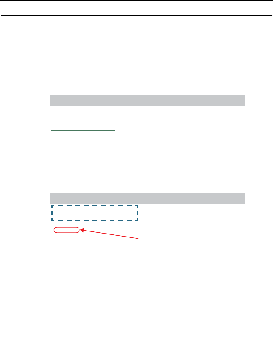
Convention (Graphics) Description
Denotes an “excerpt” from a Web page
or the visual truncation of a Web page
Denotes an area of emphasis on a Web
page
dot-dashed rectangle or
line
solid rounded rectangle
with an arrow

14
Command Line Interface
Syntax conventions for the Cayman Gateway command line interface are as
follows:
Text
The words “Cayman Gateway” and “Gateway” refer to the Netopia Cayman
Gateway.
The expressions “Release 7.2” and “R 7.2” refer to the most recent gener-
ally available Cayman Operating System.
Convention Description
straight ([ ]) brackets in cmd
line Optional command arguments
curly ({ }) brackets, with values
separated with vertical bars (|). Alternative values for an argument are
presented in curly ({ }) brackets, with
values separated with vertical bars (|).
bold terminal type
face
User-entered text
italic terminal
type face
Variables for which you supply your
own values

15
Organization
Organization
This guide consists of eight chapters, including a glossary, and an index. It
is organized as follows:
•Chapter 1, “Introduction” — Describes the Cayman document suite,
the purpose of, the audience for, and structure of this guide. It gives a
table of conventions and presents a product description summary.
•Chapter 2, “Basic Mode Setup” — Describes how to get up and run-
ning with your Cayman Gateway.
•Chapter 3, “Expert Mode” — Focuses on the “Expert Mode” Web-
based user interface for advanced users. It is organized in the same way
as the Web UI is organized. As you go through each section, functions
and procedures are discussed in detail.
•Chapter 4, “Basic Troubleshooting” — Gives some simple sugges-
tions for troubleshooting problems with your Gateway’s initial configura-
tion.
•Chapter 5, “Advanced Troubleshooting” — Gives suggestions and
descriptions of expert tools to use to troubleshoot your Gateway’s config-
uration.
•Chapter 6, “Command Line Interface” — Describes all the current
text-based commands for both the SHELL and CONFIG modes. A sum-
mary table and individual command examples for each mode is provided.
•Chapter 7, “Glossary”
•Chapter 8, “Technical Specifications and Safety Information”
•Index

16
Overview of Major Capabilities
The Netopia Gateway offers simplified setup and management features as
well as advanced broadband router capabilities. The following are some of
the main features of the Netopia Gateway:
•Wide Area Network Termination
The Gateway combines a DSL modem with an Internet router. It translates pro-
tocols used on the Internet to protocols used by home personal computers and
eliminates the need for special desktop software (i.e. PPPoE client).
•Simplified Local Area Network Setup
Built-in DHCP and DNS proxy features minimize or eliminate the need to pro-
gram any network configuration into your home personal computer.
•Management
A Web server built into the Cayman Operating System makes setup and mainte-
nance easy using standard browsers. Diagnostic tools facilitate troubleshoot-
ing.
•Security
Network Address Translation (NAT), password protection, and other built-in
security features prevent unauthorized remote access to your network. Pin-
holes, default server, and other features permit access to computers on your
home network that you can specify.
Technical details are discussed in “Expert Mode” on page 35.

17
A Word About Example Screens
A Word About Example Screens
This manual contains many example screen illustrations. Since Netopia
Cayman Series Gateways offer a wide variety of features and functionality,
the example screens shown may not appear exactly the same for your par-
ticular Gateway or setup as they appear in this manual. The example
screens are for illustrative and explanatory purposes, and should not be
construed to represent your own unique environment.

18

19
CHAPTER 2 Basic Mode Setup
Most users will find that the basic Quickstart configuration is all that they
ever need to use. This section may be all that you ever need to configure
and use your Cayman Gateway. The following instructions cover installation
in Router Mode.
This section covers:
•“Important Safety Instructions” on page 20
•“Set up the Cayman Gateway” on page 21
•“Configure the Cayman Gateway” on page 23
•“Cayman Gateway Status Indicator Lights” on page 26
•“Home Page - Basic Mode” on page 27

20
Important Safety Instructions
POWER SUPPLY INSTALLATION
Connect the power supply cord to the power jack on the Cayman Gateway.
Plug the power supply into an appropriate electrical outlet.
☛ CAUTION:
Depending on the power supply provided with the product, either
the direct plug-in power supply blades, power supply cord plug or
the appliance coupler serves as the mains power disconnect. It
is important that the direct plug-in power supply, socket-outlet or
appliance coupler be located so it is readily accessible.
CAUTION (North America Only): For use only with a CSA Certi-
fied or UL Listed Limited Power Source or Class 2 power supply,
rated 12Vdc, 1.5A.
(Sweden) Apparaten skall anslutas till jordat uttag när den
ansluts till ett nätverk
(Norway) Apparatet må kun tilkoples jordet stikkontakt.
USB-powered models: For Use with Listed I.T.E. Only
TELECOMMUNICATION INSTALLATION
When using your telephone equipment, basic safety precautions should
always be followed to reduce the risk of fire, electric shock and injury to per-
sons, including the following:
•Do not use this product near water, for example, near a bathtub, wash
bowl, kitchen sink or laundry tub, in a wet basement or near a swimming
pool.
•Avoid using a telephone (other than a cordless type) during an electrical
storm. There may be a remote risk of electrical shock from lightning.
•Do not use the telephone to report a gas leak in the vicinity of the leak.
SAVE THESE INSTRUCTIONS

21
Set up the Cayman Gateway
Set up the Cayman Gateway
Refer to your Quickstart Guide for instructions on how to connect your Cay-
man gateway to your power source, PC or local area network, and your Inter-
net access point, whether it is a dedicated DSL outlet or a DSL or cable
modem. Different Cayman Gateway models are supplied for any of these
connections. Be sure to enable Dynamic Addressing on your PC. Perform
the following:
• Windows 95, 98 and ME
• Right-Click on the Network Neighborhood icon on your Windows desk-
top and select Properties from the pull-down menu.
• In the list of network components, highlight the entry that says
“TCP/IP ([your Ethernet card here])”.
• Click the Properties button.
• Click the Obtain an IP address automatically radio button. Click the
DNS Configuration tab. Click the Disable DNS radio button. Click the
Gateway tab and remove any installed Gateways. Click the OK button
twice. When prompted, restart your PC.
Proceed to “Configure the Cayman Gateway” on page 23.
• Windows 2000 and XP
• Right Click on the My Network Places icon on your Windows desktop
and select Properties.
• Select your Local Area Connection.
• Right click on your Local Area Connection and select Properties.
• Select Internet Protocol [TCP/IP].
• Click the Properties button.
• Click the Obtain IP address automatically radio button and the Obtain
DNS server address automatically radio button. Click the OK button.

22
Proceed to “Configure the Cayman Gateway” on page 23.
• Macintosh Mac OS
Your Macintosh must be using MacOS 7.6.1 or higher.
• Select Control Panels from the Apple Menu.
• Open the TCP/IP Control Panel.
• Choose Connect via Ethernet.
• Choose Configure Using DHCP Server. Close and Save.
• You do not have to restart the Macintosh. Launch your Web browser,
such as Netscape Navigator or Internet Explorer.
Proceed to “Configure the Cayman Gateway” on page 23.
• Mac OS X
• Launch System Preferences from the Dock or from the Apple Menu.
• Select the Network Preference Pane.
• Choose Show: Built-in Ethernet.
• Click the TCP/IP tab.
• Choose Configure: Using DHCP.
• Quit System Preferences.
• You do not have to restart the Macintosh. Launch your Web browser,
such as Netscape Navigator or Internet Explorer.
Proceed to “Configure the Cayman Gateway” on page 23.
23
Configure the Cayman Gateway
Configure the Cayman Gateway
1. Run your Web browser application, such as Netscape Navigator or
Microsoft Internet Explorer, from the computer connected to the Cayman
Gateway.
Enter http://192.168.1.254 in the Location text box.
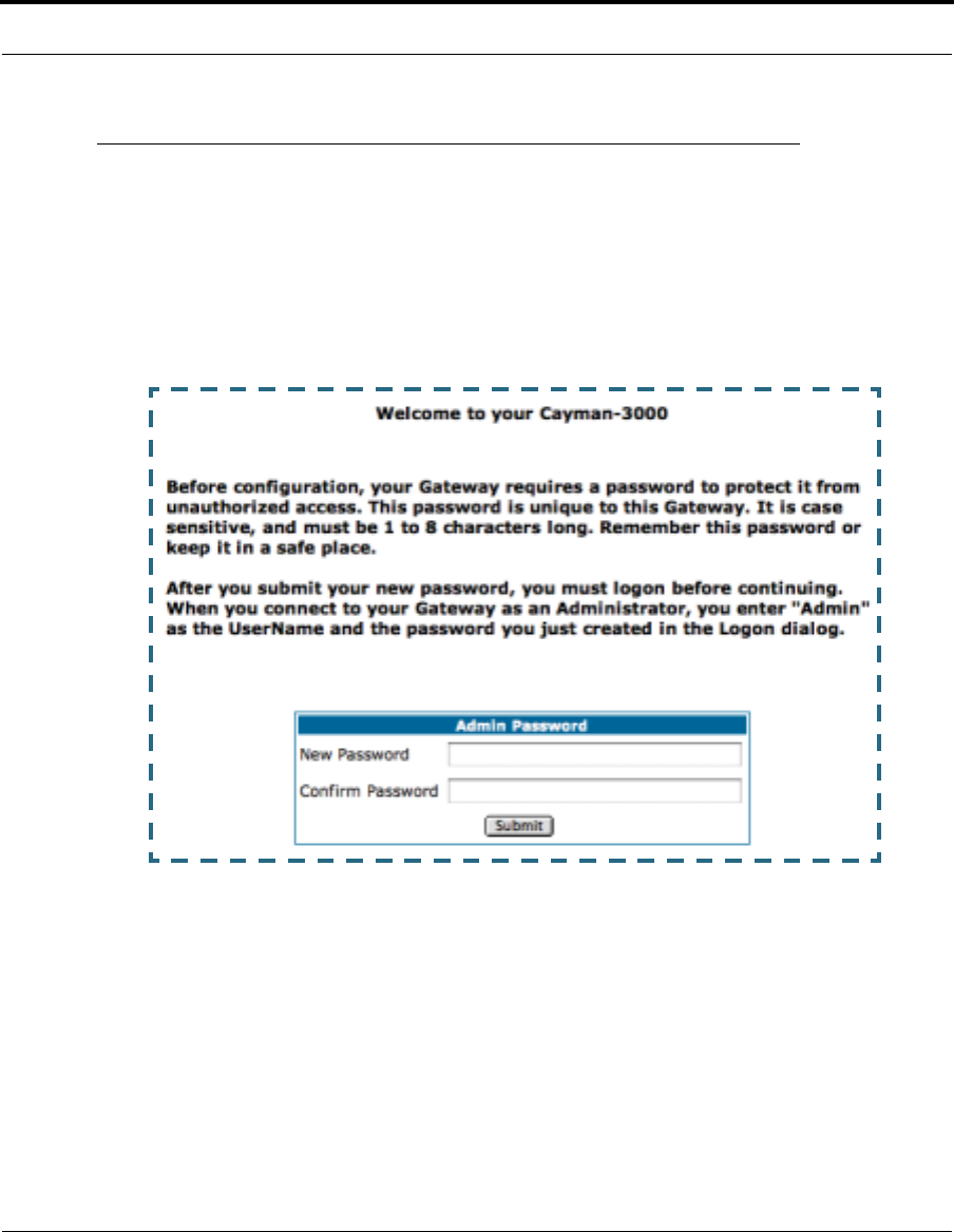
The Admin Password page appears.
Access to your Cayman device can be controlled through two access con-
trol accounts, Admin or User.
•The Admin, or administrative user, performs all configuration, manage-
ment or maintenance operations on the Gateway.
•The User account provides monitor capability only.
A user may NOT change the configuration, perform upgrades or invoke
maintenance functions.
For the security of your connection, an Admin password must be set on
the Cayman unit.
24
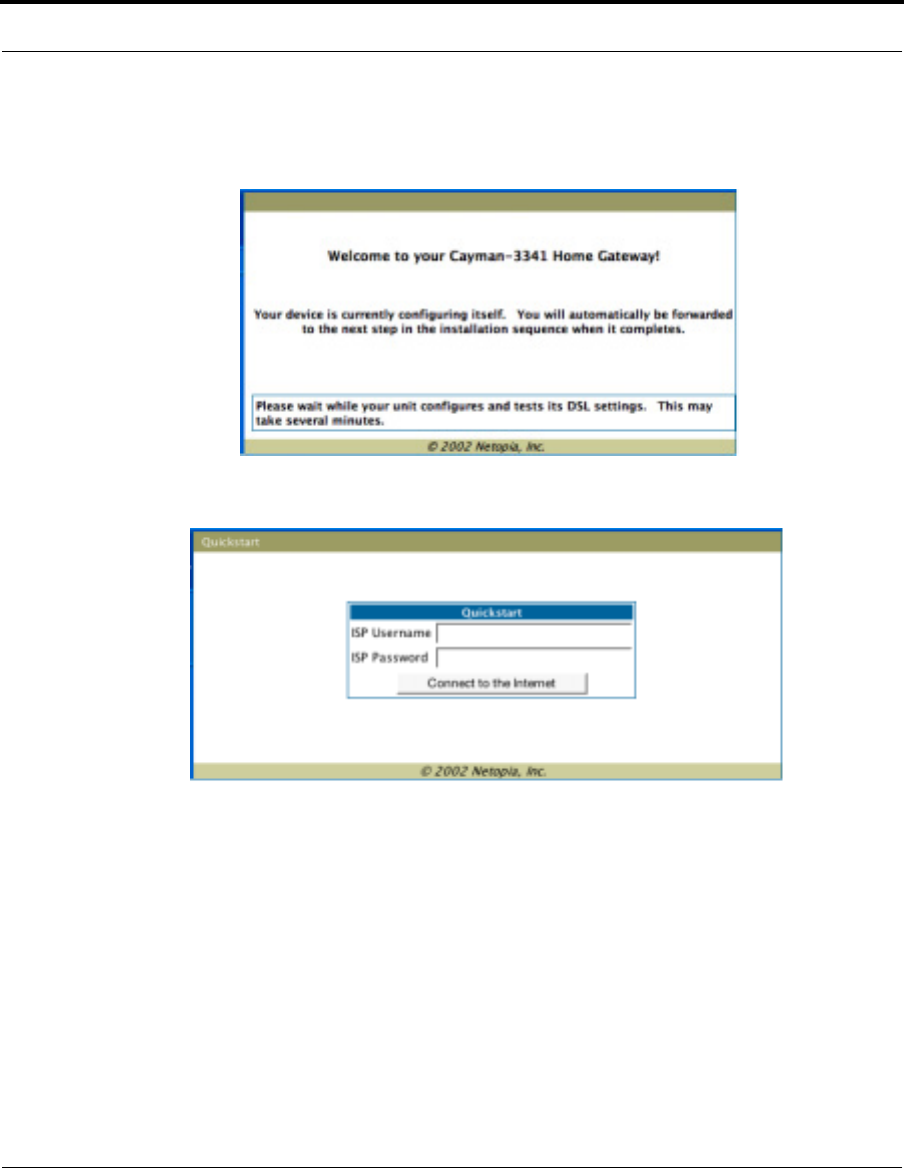
The browser then displays the Welcome page.
The browser then displays the Quickstart web page.
2. Enter the username and password supplied by your Internet Service Pro-
vider. Click the
Connect to the Internet
button.
Once you enter your username and password here, you will no longer
need to enter them whenever you access the Internet. The Cayman Gate-
way stores this information and automatically connects you to the Inter-
net.
25
Configure the Cayman Gateway
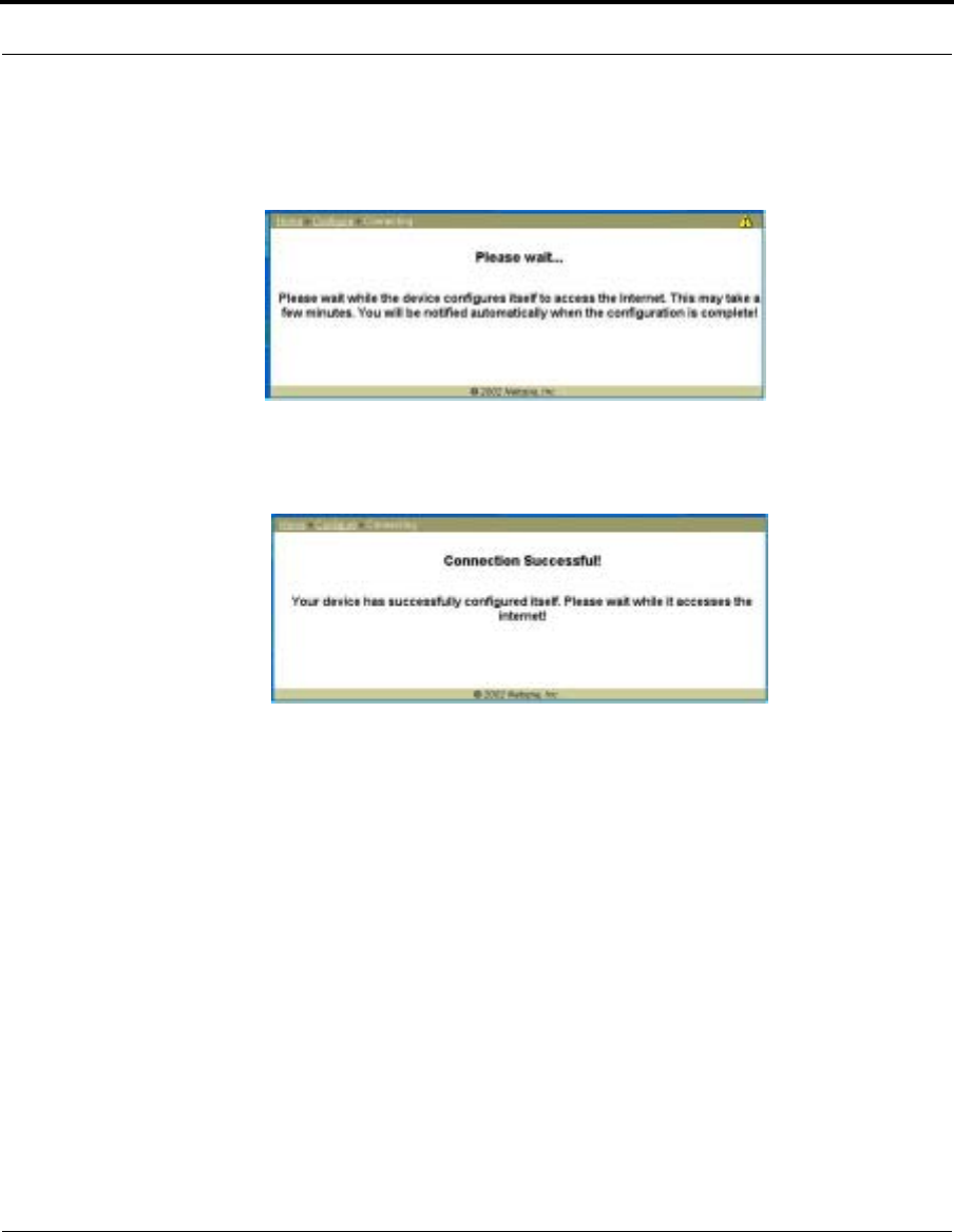
The Gateway displays a message while it configures itself.
3. When the connection succeeds, your browser will display a success
message.
Once a connection is established, your browser is redirected to your ser-
vice provider’s home page or a registration page on the Internet.
4. Congratulations! Your installation is complete. You can now surf to your
favorite Web sites by typing an URL in your browser’s location box or by
selecting one of your favorite Internet bookmarks.

26
Cayman Gateway Status Indicator Lights
Colored LEDs on your Cayman Gateway indicate the status of various port
activity. Different Gateway models have different ports for your connections
and different indicator LEDs. The Quickstart Guide accompanying your Cay-
man Gateway describes the behavior of the various indicator LEDs.
Example status indicator lights
netopia
Status Indicator Lights (LEDs)
27
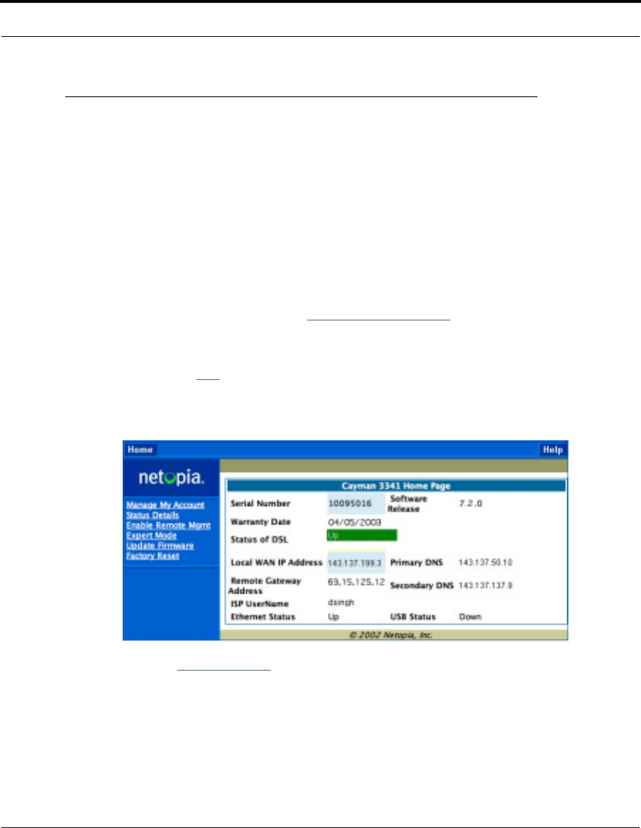
Home Page - Basic Mode
Home Page - Basic Mode
After you have performed the basic Quickstart configuration, any time you
log in to your Cayman Gateway you will access the Cayman Gateway Home
Page.
You access the Home Page by typing
http://192.168.1.254
in your Web
browser’s location box.
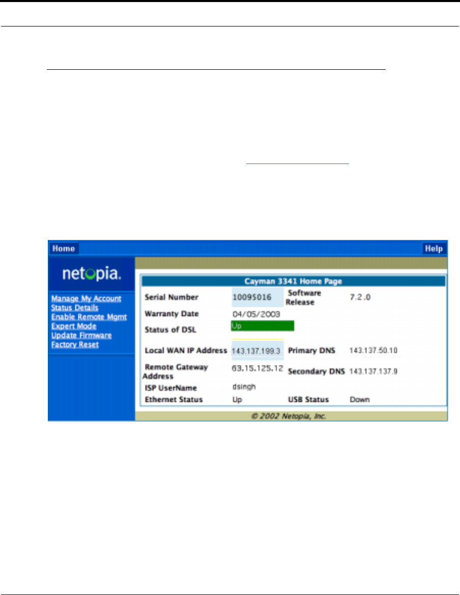
The Basic Mode Home Page appears.

28
The Home Page displays the following information in the center section:
The links in the left-hand column on this page allow you to manage or con-
figure several features of your Gateway. Each link is described in its own
section.
Item Description
Local WAN IP
Address
This is the negotiated address of the Gateway’s WAN interface.
This address is usually dynamically assigned.
Remote
Gateway
Address
This is the negotiated address of the remote router to which this
Gateway is connected.
Primary DNS
Secondary
DNS
These are the negotiated DNS addresses.
ISP Username This is your PPPoE username as assigned by your service pro-
vider.
Status of
Connection
‘Waiting for DSL’ is displayed while the Gateway is training. This
should change to ‘Up’ within two minutes.
‘Up’ is displayed when the ADSL line is synched and the PPPoE
session is established.
‘Down’ indicates inability to establish a connection; possible line
failure.
Serial Number This is the unique serial number of your Gateway.
Software
Release
This is the version number of the current embedded software in
your Gateway.
Warranty Date This is the date that your Gateway was installed and enabled.
Ethernet
Status
Local Area Network (Ethernet) is either Up or Down
USB Status If your Gateway is so equipped, Local Area Network (USB)
is either Up or Down
29
Home Page - Basic Mode
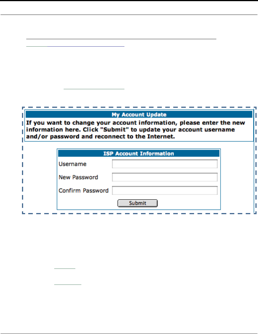
Link: Manage My Account
You can change your ISP account information for the Cayman Gateway. You
can also manage other aspects of your account on your service provider’s
account management Web site.
Click on the
Manage My Account
link. The Manage My Account page
appears.
Enter your username, and then your new password. Confirm your new pass-
word. For security, your actual passwords are not displayed on the screen
as you type. You must enter the new password twice to be sure you have
typed it correctly.
Click the
Submit
button.
Click the
Continue
button. You will be taken to your service provider’s Web
site account management page.
30
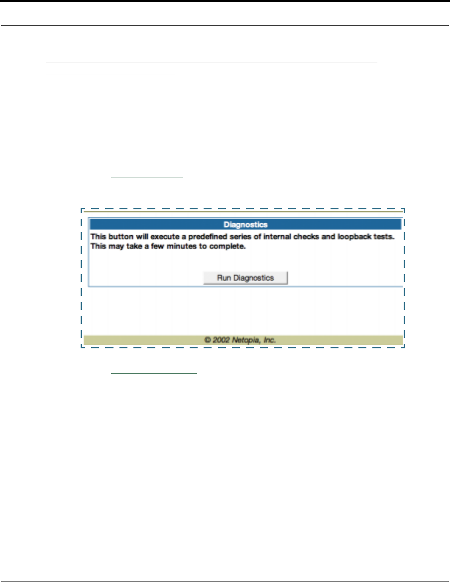
Link: Status Details
If you need to diagnose any problems with your Cayman Gateway or its con-
nection to the Internet, you can run a sophisticated diagnostic tool. It
checks several aspects of your physical and electronic connection and
reports its results on-screen. This can be useful for troubleshooting, or
when speaking with a technical support technician.
Click on the
Status Details
link. The Diagnostics page appears.
Click on the
Run Diagnostics
button to run your diagnostic tests. For a
detailed description of these tests, see “Diagnostics” on page 166.
31
Home Page - Basic Mode
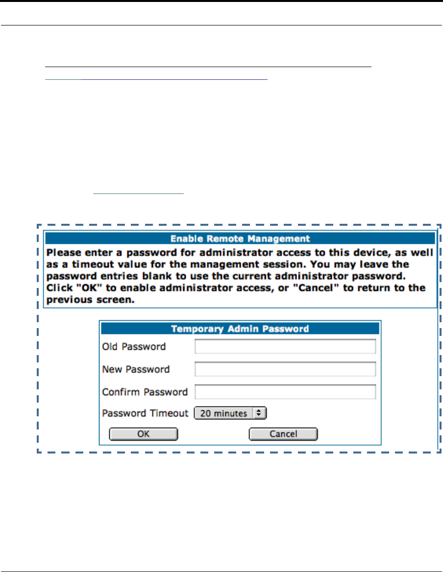
Link: Enable Remote Management
This link allows you to authorize a remotely-located person, such as a sup-
port technician, to directly access your Cayman Gateway. This is useful for
fixing configuration problems when you need expert help. You can limit the
amount of time such a person will have access to your Gateway. This will
prevent unauthorized individuals from gaining access after the time limit
has expired.
Click the
Enable Rmt Mgmt
link. The Enable Remote Management page
appears.
Since you’ve already has entered an Admin password, you can use that
Admin password or enter a new password. If you enter a new password, it
becomes the temporary Admin password. After the time-out period has
expired, the Admin password reverts to the original Admin password you
entered.
32
Enter a temporary password for the person you want to authorize, and con-
firm it by typing it again. You can select a time-out period for this password,
from 5 to 30 minutes, from the pull-down menu. Be sure to tell the autho-
rized person what the password is, and for how long the time-out is set.
Click the
Submit
button.
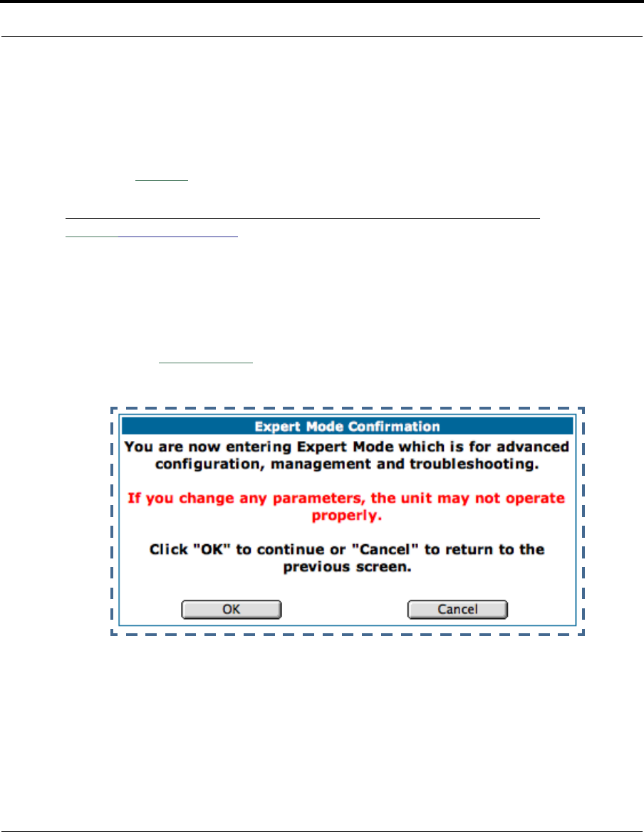
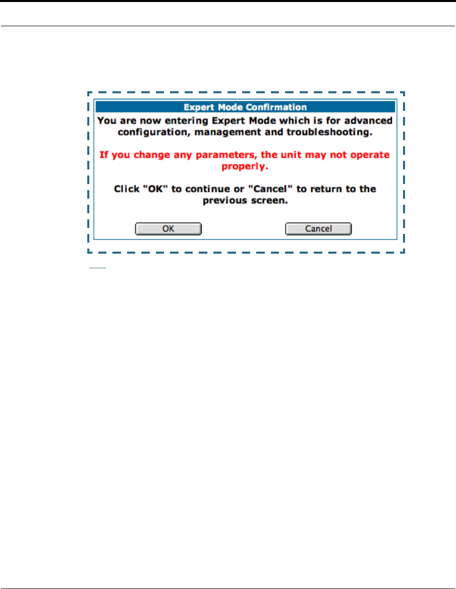
Link: Expert Mode
Most users will find that the basic Quickstart configuration is all that they
ever need to use. Some users, however, may want to do more advanced
configuration. The Cayman Gateway has many advanced features that can
be accessed and configured through the Expert Mode pages.
Click on the
Expert Mode
link to display the Expert Mode Confirmation
page.
You should carefully consider any configuration changes you want to make,
and be sure that your service provider supports them.
Once you click the OK button you will be taken to the Expert Mode Home
Page.
33
Home Page - Basic Mode
The Expert Mode Home Page is the main access point for configuring and
managing the advanced features of your Gateway. See “Expert Mode” on
page 35 for information.
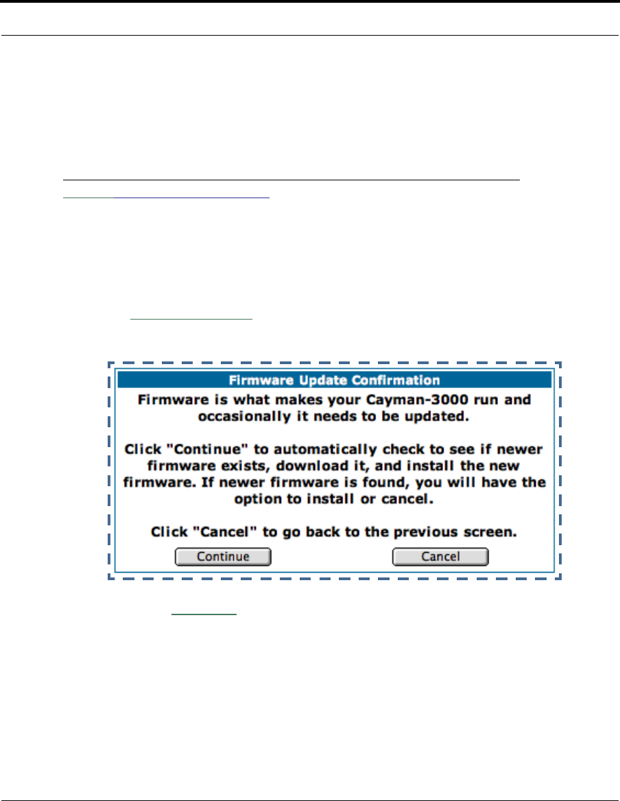
Link: Update Firmware
Periodically, the embedded firmware in your Gateway may be updated to
improve the operation or add new features. Your gateway includes its own
onboard installation capability. Your service provider may inform you when
new firmware is available, or you can check for yourself.
Click the
Update Firmware
link. The Firmware Update Confirmation page
appears.
If you click the
Continue
button, the Gateway will check a remote Firmware
Server for the latest firmware revision. If a newer version is found, your firm-
ware will be automatically updated once you confirm the installation.
34
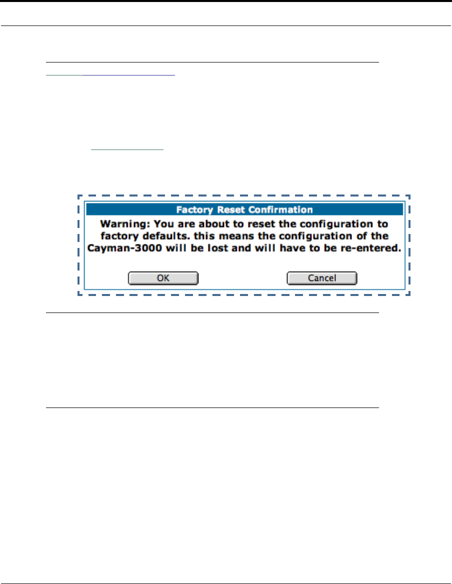
Link: Factory Reset
In some cases, you may need to clear all the configuration settings and
start over again to program the Cayman Gateway. You can perform a factory
reset to do this.
Click on
Factory Reset
to reset the Gateway back to its original factory
default settings.
☛ NOTE:
Exercise caution before performing a Factory Reset. This will
erase any configuration changes that you may have made and
allow you to reprogram your Gateway.

35
Overview of Major Capabilities
CHAPTER 3 Expert Mode
Using the Expert Mode Web-based user interface for the Netopia Cayman-
series Gateway you can configure, troubleshoot, and monitor the status of
your Gateway.
Overview of Major Capabilities
•“Wide Area Network Termination” on page 36
The Gateway combines a traditional modem with an Internet router. It translates
protocols used on the Internet to protocols used by home personal computers
and eliminates the need for special desktop software (i.e. PPPoE).
•“Simplified Local Area Network Setup” on page 38
Built-in DHCP and DNS proxy features minimize or eliminate the need to pro-
gram any network configuration into your home personal computer.

36
•“Management” on page 39
A Web server built into the Cayman Operating System makes setup and mainte-
nance easy using standard browsers. Diagnostic tools facilitate troubleshoot-
ing.
•“Security” on page 40
Network Address Translation (NAT), password protection, and other built-in
security features prevent unauthorized remote access to your network. Pin-
holes, default server, and other features permit access to computers on your
home network that you can specify.
Wide Area Network Termination
PPPoE/PPPoA (Point-to-Point Protocol over Ethernet/ATM). The PPPoE
specification, incorporating the PPP and Ethernet standards, allows your
computer(s) to connect to your Service Provider’s network through your
Ethernet WAN connection. The Cayman-series Gateway supports PPPoE/
PPPoA, eliminating the need to install PPPoE client software on any LAN
computers.
Service Providers may require the use of PPP authentication protocols such
as Challenge Handshake Authentication Protocol (CHAP) or Password
Authentication Protocol (PAP). CHAP and PAP use a username and password
pair to authenticate users with a PPP server.
A CHAP authentication process works as follows:
1. The password is used to scramble a challenge string.
2. The password is a shared secret, known by both peers.
3. The unit sends the scrambled challenge back to the peer.
PAP, a less robust method of authentication, sends a username and pass-
word to a PPP server to be authenticated. PAP’s username and password
pair are not encrypted, and are therefore sent “unscrambled”.

37
Overview of Major Capabilities
Instant-On PPP. You can configure your Gateway for one of two types of
Internet connections:
•Always On
•Instant On
These selections provide either an uninterrupted Internet connection or an
as-needed connection.
While an Always On connection is convenient, it does leave your network
permanently connected to the Internet, and therefore potentially vulnerable
to attacks.
Cayman's Instant On technology furnishes almost all the benefits of an
Always-On connection while providing two additional security benefits:
•Your network cannot be attacked when it is not connected.
•Your network may change address with each connection making it more
difficult to attack.
When you configure Instant On access, you can also configure an idle time-
out value. Your Gateway monitors traffic over the Internet link and when
there has been no traffic for the configured number of seconds, it discon-
nects the link.
When new traffic that is destined for the Internet arrives at the Gateway, the
Gateway will instantly re-establish the link.
Your service provider may be using a system that assigns the Internet
address of your Gateway out of a pool of many possible Internet addresses.
The address assigned varies with each connection attempt, which makes
your network a moving target for any attacker.

38
Simplified Local Area Network Setup
DHCP (Dynamic Host Configuration Protocol) Server. DHCP Server
functionality enables the Gateway to assign to your LAN computer(s) a “pri-
vate” IP address and other parameters that allow network communication.
The default DHCP Server configuration of the Gateway supports up to 253
LAN IP addresses.
This feature simplifies network administration because the Gateway main-
tains a list of IP address assignments. Additional computers can be added
to your LAN without the hassle of configuring an IP address.
DNS Proxy. Domain Name System (DNS) provides end users with the abil-
ity to look for devices or web sites by typing their names, rather than IP
addresses. For web surfers, this technology allows you to enter the URL
(Universal Resource Locator) as text to surf to a desired website.
The Cayman DNS Proxy feature allows the LAN-side IP address of the Gate-
way to be used for proxying DNS requests from hosts on the LAN to the
DNS Servers configured in the gateway. This is accomplished by having the
Gateway's LAN address handed out as the “DNS Server” to the DHCP cli-
ents on the LAN.

39
Overview of Major Capabilities
☛ NOTE:
The Cayman DNS Proxy only proxies UDP DNS queries, not TCP
DNS queries.
Management
Embedded Web Server. There is no specialized software to install on your
PC to configure, manage, or maintain your Cayman Gateway. Web pages
embedded in the operating system provide access to the following Gateway
operations:
•Setup
•System and security logs
•Diagnostics functions
Once you have removed your Cayman Gateway from its packing container
and powered the unit up, use any LAN attached PC or workstation running a
common web browser application to configure and monitor the Gateway.
Diagnostics. In addition to the Gateway’s visual LED indicator lights, you
can run an extensive set of diagnostic tools from your Web browser.
Two of the facilities are:
•Automated “Multi-Layer” Test
The
Run Diagnostics
link initiates a sequence of tests. They examine the
entire functionality of the Gateway, from the physical connections to the
data traffic.
•Network Test Tools
Three test tools to determine network reachability are available:

40
Ping - tests the “reachability” of a particular network destination by
sending an ICMP echo request and waiting for a reply.
NSLookup - converts a domain name to its IP address and vice versa.
TraceRoute - displays the path to a destination by showing the number
of hops and the router addresses of these hops.
The system log also provides diagnostic information.
☛ NOTE:
Your Service Provider may request information that you acquire
from these various diagnostic tools. Individual tests may be per-
formed at the command line. (See “Command Line Interface” on
page 171.).
Security
Remote Access Control. You can determine whether or not an administra-
tor or other authorized person has access to configuring your Gateway. This
access can be turned on or off in the Web interface.
Password Protection. Access to your Cayman device can be controlled
through two access control accounts, Admin or User.
•The Admin, or administrative user, performs all configuration, manage-
ment or maintenance operations on the Gateway.
•The User account provides monitor capability only.
A user may NOT change the configuration, perform upgrades or invoke
maintenance functions.
Network Address Translation (NAT). The Cayman Gateway Network
Address Translation (NAT) security feature lets you conceal the topology of a

41
Overview of Major Capabilities
hard-wired Ethernet or wireless network connected to its LAN interface from
routers on networks connected to its WAN interface. In other words, the
end computer stations on your LAN are invisible from the Internet.
Only a single WAN IP address is required to provide this security support
for your entire LAN.
LAN sites that communicate through an Internet Service Provider typically
enable NAT, since they usually purchase only one IP address from the ISP.
•When NAT is ON, the Cayman Gateway “proxies” for the end computer
stations on your network by pretending to be the originating host for net-
work communications from non-originating networks. The WAN interface
address is the only IP address exposed.
The Cayman Gateway tracks which local hosts are communicating with
which remote hosts. It routes packets received from remote networks to
the correct computer on the LAN (Ethernet) interface.
•When NAT is OFF, a Cayman Gateway acts as a traditional TCP/IP router,
all LAN computers/devices are exposed to the Internet.
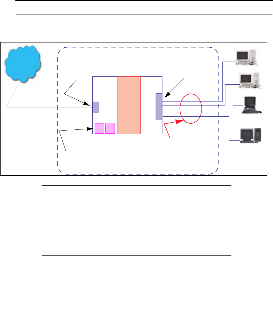
A diagram of a typical NAT-enabled LAN follows:
42
☛ NOTE:
1. The default setting for NAT is ON.
2. Cayman uses Port Address Translation (PAT) to implement the
NAT facility.
3. NAT Pinhole traffic (discussed below) is always initiated from
the WAN side.
Cayman Advanced Features for NAT. Using the NAT facility provides
effective LAN security. However, there are user applications that require
methods to selectively by-pass this security function for certain types of
Internet traffic.
WAN
Interface
LAN
Ethernet
Interface
Cayman Gateway
NAT
Internet
Embedded Admin Services:
HTTP-Web Server and Telnet Server Port
NAT-protected
LAN stations
Ethernet

43
Overview of Major Capabilities
Cayman Gateways provide special pinhole configuration rules that enable
users to establish NAT-protected LAN layouts that still provide flexible by-
pass capabilities.
Some of these rules require coordination with the unit’s embedded admin-
istration services: the internal Web (HTTP) Port (TCP 80) and the internal
Telnet Server Port (TCP 23).
Internal Servers. The internal servers are the embedded Web and Telnet
servers of the Gateway. You would change the internal server ports for Web
and Telnet of the Gateway if you wanted to have these services on the LAN
using pinholes or the Default server. Pinhole configuration rules provide an
internal port forwarding facility that enables you to eliminate conflicts with
embedded administrative ports 80 and 23.
Pinholes. This feature allows you to:
•Transparently route selected types of network traffic using the port for-
warding facility.
FTP requests or HTTP (Web) connections are directed to a specific host
on your LAN.
•Setup multiple pinhole paths.
Up to 32 paths are supported
•Identify the type(s) of traffic you want to redirect by port number.
Common TCP/IP protocols and ports are:
See page 78 for How To instructions.
FTP (TCP 21) telnet (TCP 23)
SMTP (TCP 25) HTTP (TCP 80)
SNMP (TCP 161, UDP 161)

44
Default Server. This feature allows you to:
•Direct your Gateway to forward all externally initiated IP traffic (TCP and
UDP protocols only) to a default host on the LAN.
•Enable it for certain situations:
Where you cannot anticipate what port number or packet protocol an in-
bound application might use.
For example, some network games select arbitrary port numbers when a
connection is opened.
When you want all unsolicited traffic to go to a specific LAN host.
Combination NAT Bypass Configuration. Specific pinholes and Default
Server settings, each directed to different LAN devices, can be used
together.
☛ WARNING:
Creating a pinhole or enabling a Default Server allows inbound
access to the specified LAN station. Contact your Network Admin-
istrator for LAN security questions.
IP-Passthrough. Cayman OS now offers an IP passthrough feature. The IP
passthrough feature allows a single PC on the LAN to have the Gateway’s
public address assigned to it. It also provides PAT (NAPT) via the same pub-
lic IP address for all other hosts on the private LAN subnet.
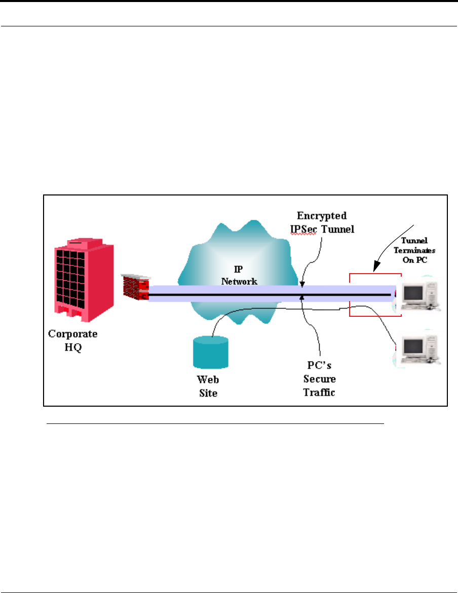
VPN IPSec Pass Through. This Cayman service supports your indepen-
dent VPN client software in a transparent manner. Cayman has imple-
mented an Application Layer Gateway (ALG) to support multiple PCs running
IP Security protocols.
This feature has three elements:
45
Overview of Major Capabilities
1. On power up or reset, the address mapping function (NAT) of the Gate-
way’s WAN configuration is turned on by default.
2. When you use your third-party VPN application, the Gateway recognizes
the traffic from your client and your unit. It allows the packets to pass
through the NAT “protection layer” via the encrypted IPSec tunnel.
3. The encrypted IPSec tunnel is established “through” the Gateway.
A typical VPN IPSec Tunnel pass through is diagrammed below:
☛ NOTE:
Typically, no special configuration is necessary to use the IPSec
pass through feature.
In the diagram, VPN PC clients are shown behind the Cayman
Gateway and the secure server is at Corporate Headquarters
across the WAN. You cannot have your secure server behind the
Cayman Gateway.
When multiple PCs are starting IPSec sessions, they must be
Cayman
Gateway

46
started one at a time to allow the associations to be created and
mapped.
VPN IPSec Tunnel Termination. This Cayman service supports termina-
tion of VPN IPsec tunnels at the Gateway. This permits tunnelling from the
Gateway without the use of third-party VPN client software on your client
PCs.
Stateful Inspection Firewall. Stateful inspection is a security feature that
prevents unsolicited inbound access when NAT is disabled. You can config-
ure UDP and TCP “no-activity” periods that will also apply to NAT time-outs if
stateful inspection is enabled on the interface.
47
Access the Web Interface
Access the Web Interface
Open the Web Connection
Once your Gateway is powered up, you can use any recent version of the
best-known web browsers such as Netscape Navigator or Microsoft Internet
Explorer from any LAN-attached PC or workstation. The procedure is:
1. Enter the name or IP address of your Cayman Gateway in the Web
browser's window and press Return.
For example, you would enter
http://192.168.1.254
.
2. If an administrator or user password has been assigned to the Cayman
Gateway, enter
Admin
or
User
as the username and the appropriate pass-
word and click
OK
.
The Basic Mode Home Page opens.
3. Click on the
Expert Mode
link in the left-hand column of links.
48
You are challenged to confirm your choice.
Click
OK
.
The Home Page opens in Expert Mode.
49
Access the Web Interface
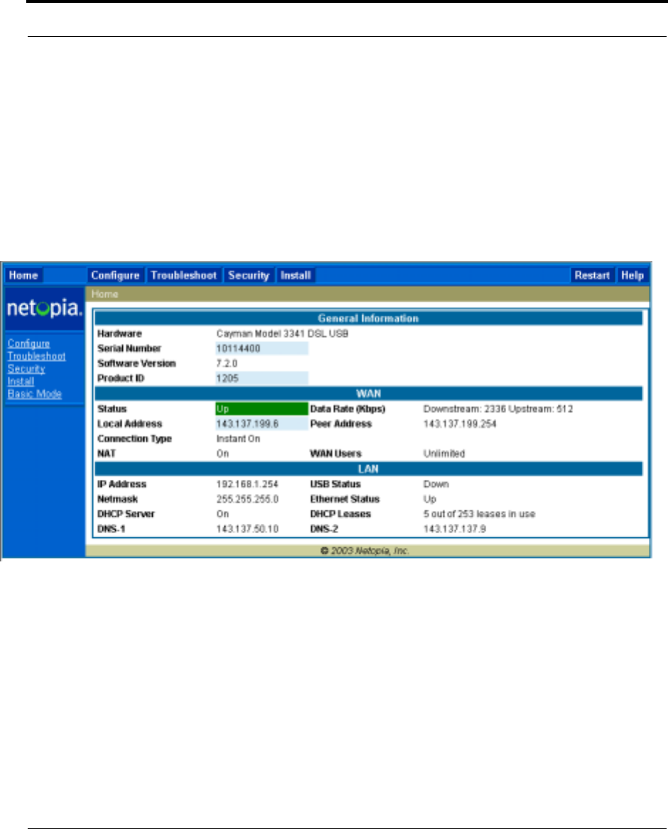
Home Page - Expert Mode
The Home Page is the summary page for your Cayman Gateway. The toolbar
at the top provides links to controlling, configuring, and monitoring pages.
Critical configuration and operational status is displayed in the center sec-
tion.

50
Home Page - Information
The Home page’s center section contains a summary of the Gateway’s
configuration settings and operational status.
Summary Information
Field Status and/or Description
General Information
Hardware Model number and summary specification
Serial Number Unique serial number, located on label attached to bottom of unit
Software Version Release and build number of running Cayman Operating System.
Product ID Refers to internal circuit board series; useful in determining which software
upgrade applies to your hardware type.
WAN
Status Wide Area Network may be
Waiting for DSL
(or other waiting status),
Up
or
Down
Data Rate (Kbps) Once connected, displays DSL speed rate, Downstream and Upstream
Local Address IP address assigned to the WAN port.
Peer Address The IP address of the gateway to which the connection defaults. If doing
DHCP, this info will be acquired. If doing PPP, this info will be negotiated.
Connection Type May be either Instant On or Always On.
NAT
On
or
Off
.
ON
if using Network Address Translation to share the IP address
across many LAN users.
WAN Users Displays the number of users allotted and the total number available for use.
LAN
IP Address Internal IP address of the Cayman Gateway.
Netmask Defines the IP subnet for the LAN
Default is 255.255.255.0 for a Class C device
DHCP Server
On
or
Off
.
ON
if using DHCP to get IP addresses for your LAN client
machines.
DHCP Leases A “lease” is held by each LAN client that has obtained an IP address
through DHCP.
DNS The default IP address of the current DNS server, if not specified. 0.0.0.0
means that the gateway address is supplied from the WAN.

51
Toolbar
Toolbar
The toolbar is the dark blue bar at the top of the page containing the major
navigation buttons. These buttons are available from almost every page,
allowing you to move freely about the site.
Home Configure Troubleshoot Security Install Restart Help
Quickstart System Status Passwords Install Key
LAN Network Tools Firewall Install Software
WAN Diagnostics IPSec
Advanced Security
Log
52
Navigating the Web Interface
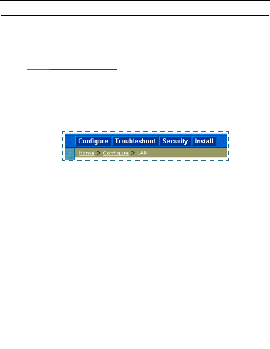
Link: Breadcrumb Trail
The breadcrumb trail is built in the light brown area beneath the toolbar. As
you navigate down a path within the site, the trail is built from left to right.
To return anywhere along the path from which you came, click on one of the
links.
53
Restart
Restart
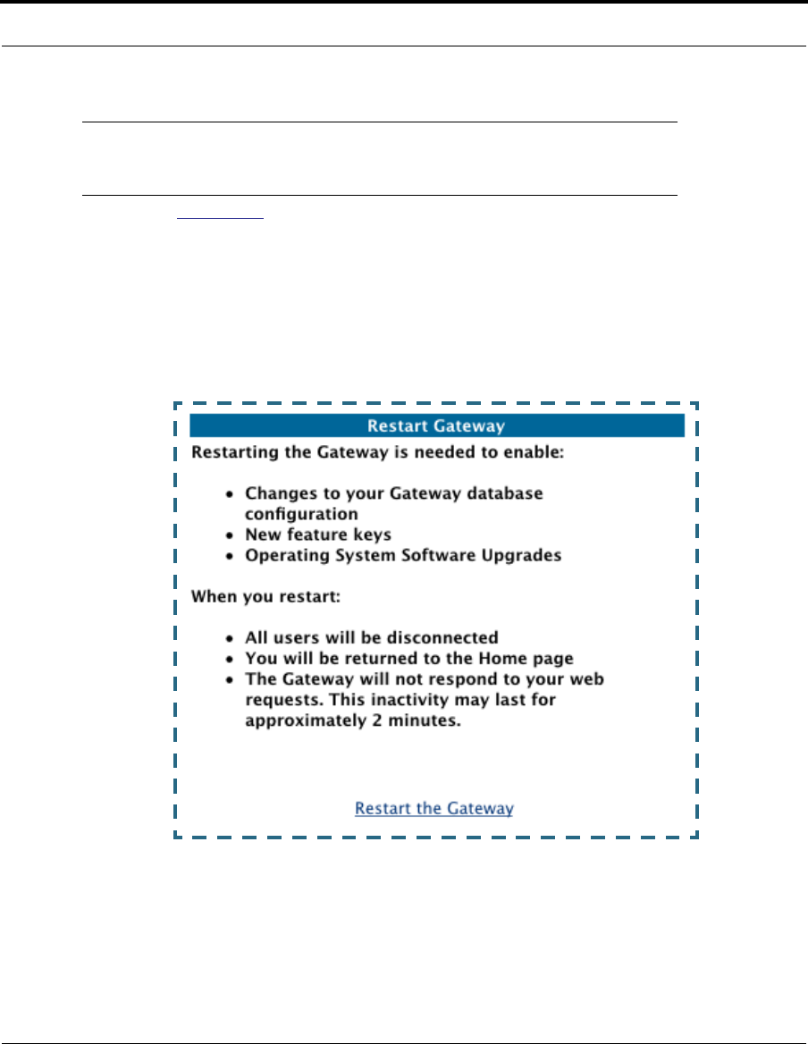
Button: Restart
The Restart button on the toolbar allows you to restart the Gateway at any
time. You will be prompted to confirm the restart before any action is taken.
The Restart Confirmation message explains the consequences of and rea-
sons for restarting the Gateway.
54
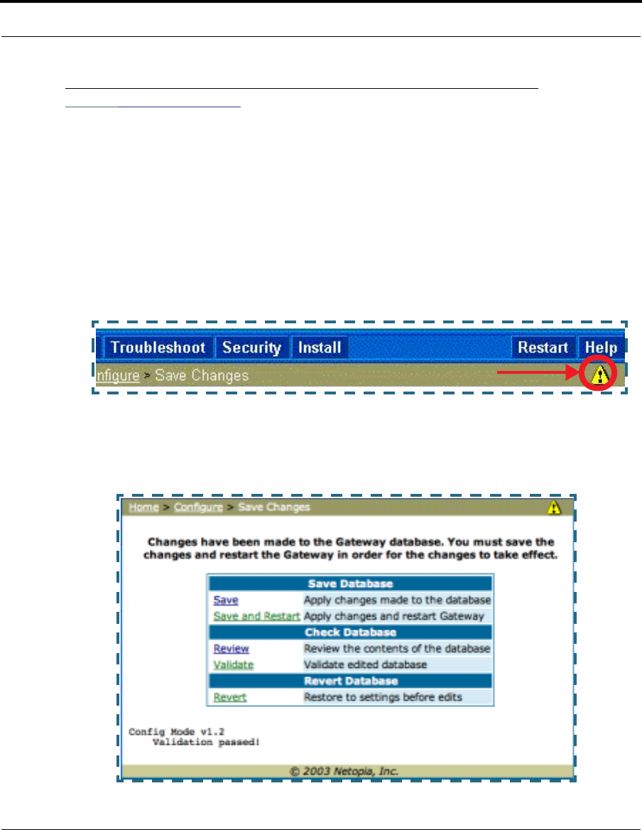
Link: Alert Symbol
The Alert symbol appears in the upper right corner if you make a database
change; one in which a change is made to the Gateway’s configuration. The
Alert serves as a reminder that you must Save the changes and Restart
the Gateway before the change will take effect. You can make many
changes on various pages, and even leave the browser for up to 5 minutes,
but if the Gateway is restarted before the changes are applied, they will be
lost. When you click on the Alert symbol, the Save Changes page appears.
Here you can select various options to save or discard these changes.
If more than one Alert is triggered, you will need to take action to clear the
first Alert before you can see the second Alert.
55
Help
Help
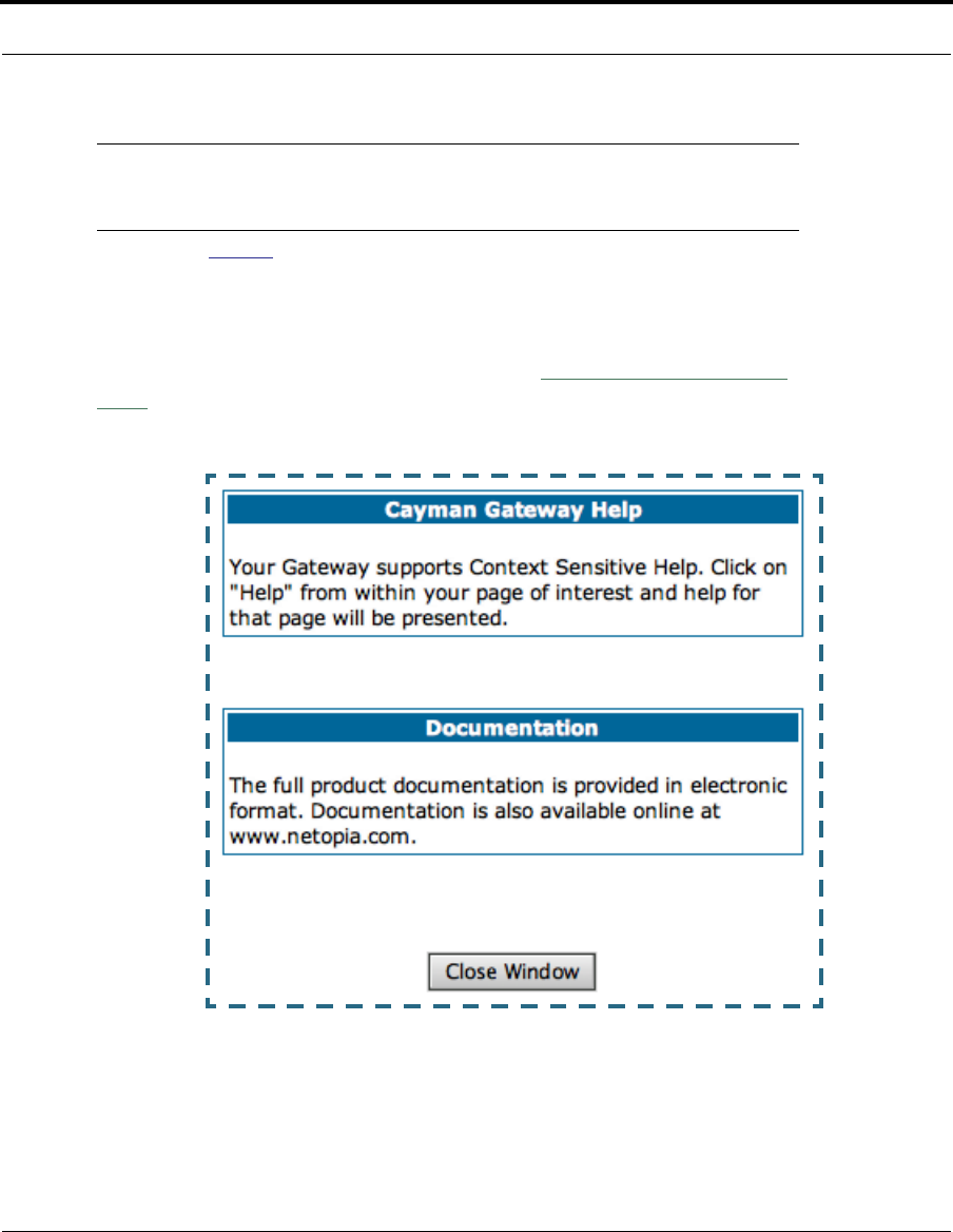
Button: Help
Context-sensitive Help is provided in CaymanOS. The page shown here is
displayed when you are on the Home page or other transitional pages. To
see a context help page example, go to
Security -> Passwords
, then click
Help
.

56
Configure
Button: Configure
The Configuration options are presented in the order of likelihood you will
need to use them. Quickstart is typically accessed during the hardware
installation and initial configuration phase. Often, these settings should
be changed only in accordance with information from your Service
Provider. LAN and WAN settings are available to fine-tune your system.
Advanced provides some special capabilities typically used for gaming or
small office environments, or where LAN-side servers are involved.
☛ This button will not be available if you log on as User.
Quickstart
How to Use the Quickstart Page. Quickstart is normally used immedi-
ately after the new hardware is installed. When you are first configuring your
Gateway, Quickstart appears first.
(Once you have configured your Gateway, logging on displays the Home
page. Thereafter, if you need to use Quickstart, choose it from the Expert
Mode Configure menu.)
Link: Configure -> Quickstart
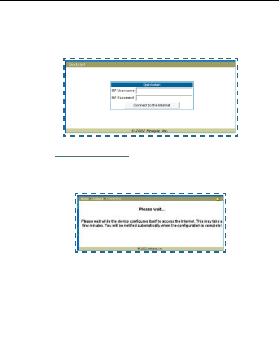
Setup Your Gateway using a PPP Connection.
This example screen is the for a PPP Quickstart configuration. Your gate-
way authenticates with the Service Provider equipment using the ISP User-
57
Configure
name and Password. These values are given to you by your Service
Provider.
1. Enter your ISP Username and ISP Password.
2. Click
Connect to the Internet
.
A brief message is displayed while the Gateway attempts to establish a con-
nection.
3. When the connection succeeds, your browser will display your Service
Provider’s home page.
If you encounter any problems connecting, refer to the chapters “Basic
Troubleshooting” on page 147 or “Advanced Troubleshooting” on
page 157.
58
LAN
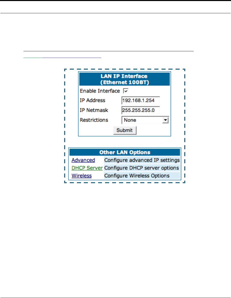
Link: Configure -> LAN
* Enable Interface: Enables all LAN-connected computers to share
resources and to connect to the WAN. The Interface should always be
enabled unless you are instructed to disable it by your Service Provider dur-
ing troubleshooting.
* IP Address: The LAN IP Address of the Gateway. The IP Address you
assign to your LAN interface must not be used by another device on your
LAN network.
* IP Netmask: Specifies the subnet mask for the TCP/IP network con-
nected to the virtual circuit. The subnet mask specifies which bits of the 32-
bit binary IP address represent network information. The default subnet
mask for most networks is 255.255.255.0 (Class C subnet mask.)
59
Configure
* Restrictions: Specifies whether an administrator can open a Web Admin-
istrator or Telnet connection to the Gateway over the LAN interface in order
to monitor and configure the Gateway. On the LAN Interface, you can enable
or disable administrator access. By default, administrative restrictions are
turned off, meaning an administrator can open a Web Administrator or Tel-
net connection through the LAN Interface.
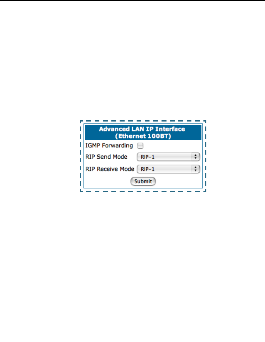
• Advanced: Clicking on the Advanced link displays the Advanced LAN IP
Interface page.
•IGMP Forwarding: The default setting is Disabled. If you check this
option, it will enable Internet Group Management Protocol (IGMP) multi-
cast forwarding. IGMP allows a router to determine which host groups
have members on a given network segment.
•RIP Send Mode: Specifies whether the gateway should use Routing
Information Protocol (RIP) broadcasts to advertise its routing tables to
other routers on your network. You may choose from the following proto-
cols:
• RIP-1: Routing Information Protocol version 1
• RIP-2: RIP Version 2 is an extension of the original Routing Information
Protocol (RIP-1) that expands the amount of useful information in the RIP
packets. While RIP-1 and RIP-2 share the same basic algorithms, RIP-2
supports several new features, including inclusion of subnet masks in
RIP packets and implementation of multicasting instead of broadcasting
(which reduces the load on hosts which do not support routing protocols.
60
• RIP-1 compatibility: Compatible with RIP version 1
• RIP-2 with MD5: MD5 authentication is an extension of RIP-2 that
increases security by requiring an authentication key when routes are
advertised.
• RIP MD5 Key: Secret password when using RIP-2 with MD5.
•RIP Receive Mode: Specifies whether the Gateway should use Routing
Information Protocol (RIP) broadcasts to update its routing tables with
information received from other routers on your network. The protocol
choices are the same as for the RIP send mode.
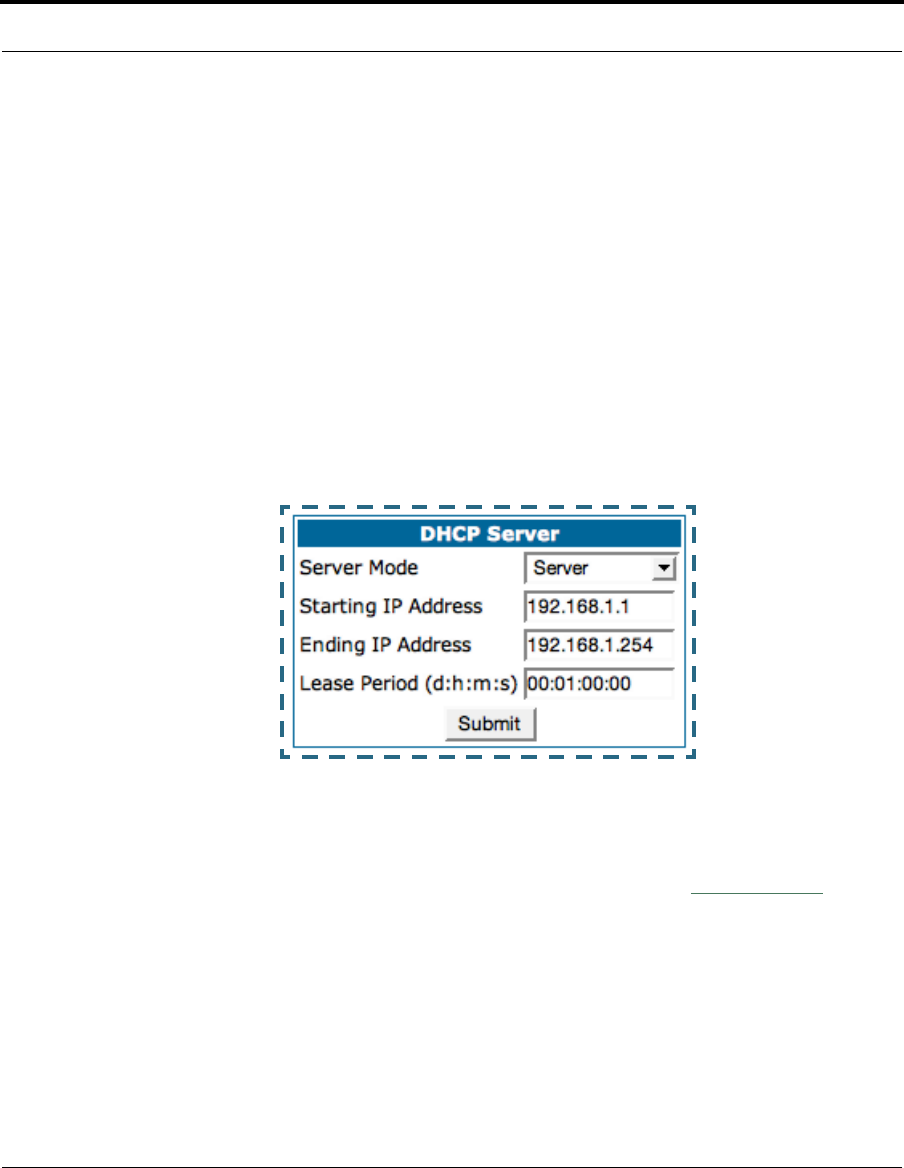
• DHCP Server: Your Gateway can provide network configuration informa-
tion to computers on your LAN, using the Dynamic Host Configuration Proto-
col (DHCP).
If you already have a DHCP server on your LAN, you should turn this service
off.
If you want the Gateway to provide this service, click the
Server Mode
pull-
down menu, choose Server, then configure the range of IP addresses that
you would like the Gateway to hand out to your computers.
You can also specify the length of time the computers can use the configu-
ration information; DHCP calls this period the lease time.
61
Configure
Your Service Provider may, for certain services, want to provide configura-
tion from its DHCP servers to the computers on your LANs. In this case, the
Gateway will relay the DHCP requests from your computers to a DHCP
server in the Service Provider's network. Click the relay-agent and enter the
IP address of the Service Provider's DHCP server in the Server Address
field. This address is furnished by the Service Provider.
☛ NOTE:
This option only works when NAT is off and the gateway is in
router mode.
• Wireless: If your Gateway is a wireless model (such as a 3347W) you can
enable or disable the wireless LAN by clicking the
Wireless
link.
Wireless functionality is enabled by default.

62
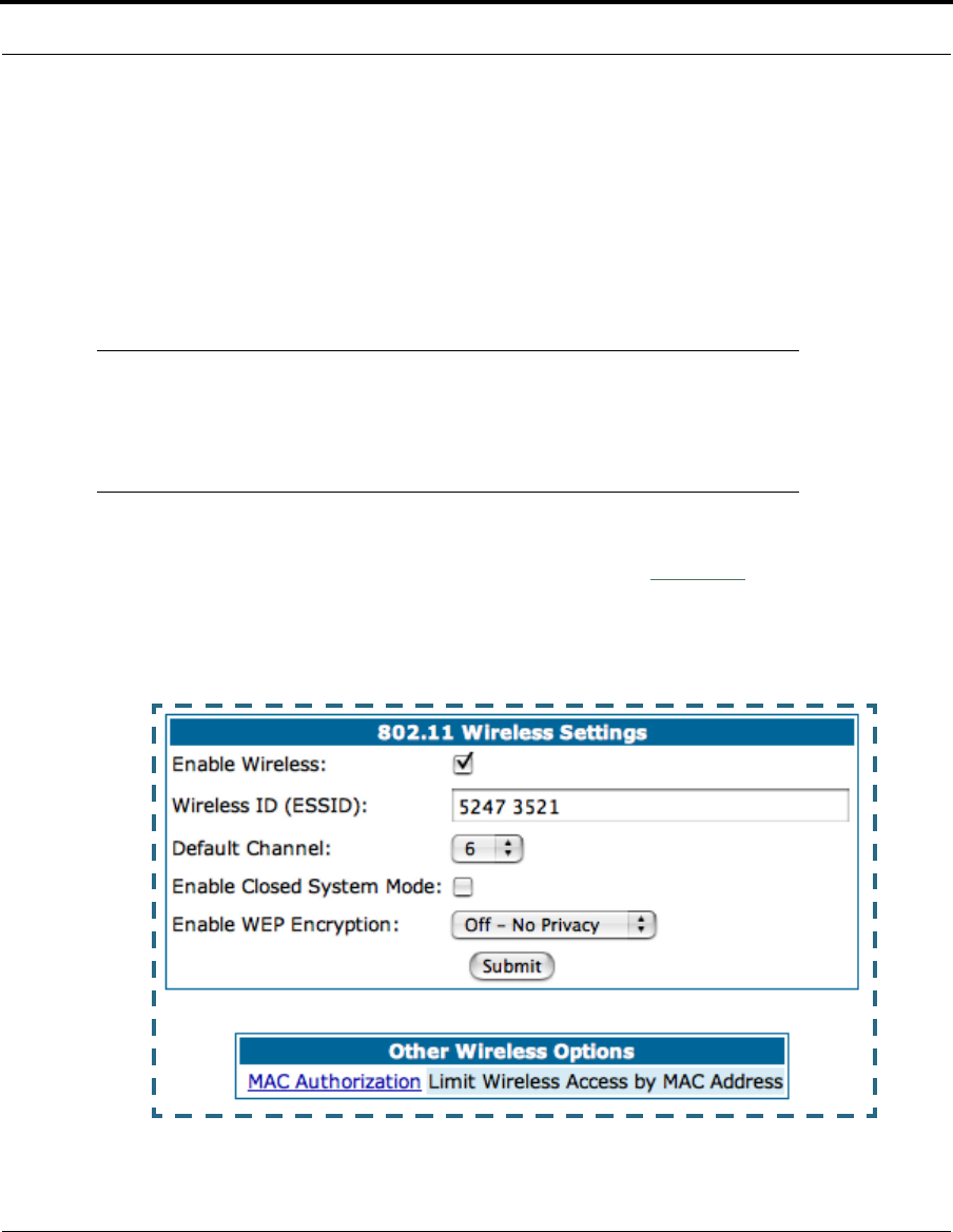
If you uncheck the Enable Wireless checkbox, the Wireless Options are
disabled, and the Gateway will not provide or broadcast any wireless LAN
services.
Wireless ID (ESSID): The ESSID is preset to a number that is unique to
your unit. You can either leave it as is, or change it by entering a freeform
name of up to 32 characters, for example “Ed’s Wireless LAN”. On client
PCs’ software, this might also be called the Network Name. The ESSID is
used to identify this particular wireless LAN. Depending on their operating
system or client wireless card, users must either:
•select from a list of available wireless LANs that appear in a scanned list
on their client
•or, if you are in Closed System Mode (see Enable Closed System
Mode below), enter this name on their clients in order to join this wire-
less LAN.
You can then configure:
Default Channel: (1 through 11) on which the network will broadcast. This
is a frequency range within the 2.4Ghz band. Channel selection depends on
government regulated radio frequencies that vary from region to region. The
widest range available is from 1 to 14. However, in North America only 1 to
11 may be selected. Europe, France, Spain and Japan will differ. Channel
selection can have a significant impact on performance, depending on
other wireless activity close to this Gateway. Channel selection is not nec-
essary at the client computers; the clients will scan the available channels
seeking access points using the same ESSID as the client.
Enable Closed System Mode: If enabled, Closed System Mode hides the
wireless network from the scanning features of wireless client computers.
Unless both the wireless clients and the Router share the same SSID in
Closed System mode, the Router’s wireless LAN will not appear as an avail-
able network when scanned for by wireless-enabled computers. Members of

63
Configure
the Closed System WLAN must log onto the Router’s wireless network with
the identical SSID as that configured in the router.
Closed System mode is an ideal way to increase wireless security and to
prevent casual detection by unwanted neighbors, office users, or malicious
users such as hackers.
If you do not enable Closed System Mode, it is more convenient, but poten-
tially less secure, for clients to access your WLAN by scanning available
access points. You must decide based on your own network requirements.
About Closed System Mode
Enabling Closed System Mode on your wireless Gateway provides another
level of security, since your wireless LAN will no longer appear as an avail-
able access point to client PCs that are casually scanning for one.
Your own wireless network clients, however, must log into the wireless LAN
by using the exact SSID of the Cayman Gateway.
In addition, if you have enabled WEP encryption on the Cayman Gateway,
your network clients must also have WEP encryption enabled, and must
have the same WEP encryption key as the Cayman Gateway.
Once the Cayman Gateway is located by a client computer, by setting the cli-
ent to a matching SSID, the client can connect immediately if WEP is not
enabled. If WEP is enabled then the client must also have WEP enabled and
a matching WEP key.
Wireless client cards from different manufacturers and different operating
systems accomplish connecting to a wireless LAN and enabling WEP in a
variety of ways. Consult the documentation for your particular wireless card
and/or operating system.
Enable WEP Encryption: You can provide a level of data security by
enabling WEP (Wired Equivalent Privacy) for encryption of network data. You
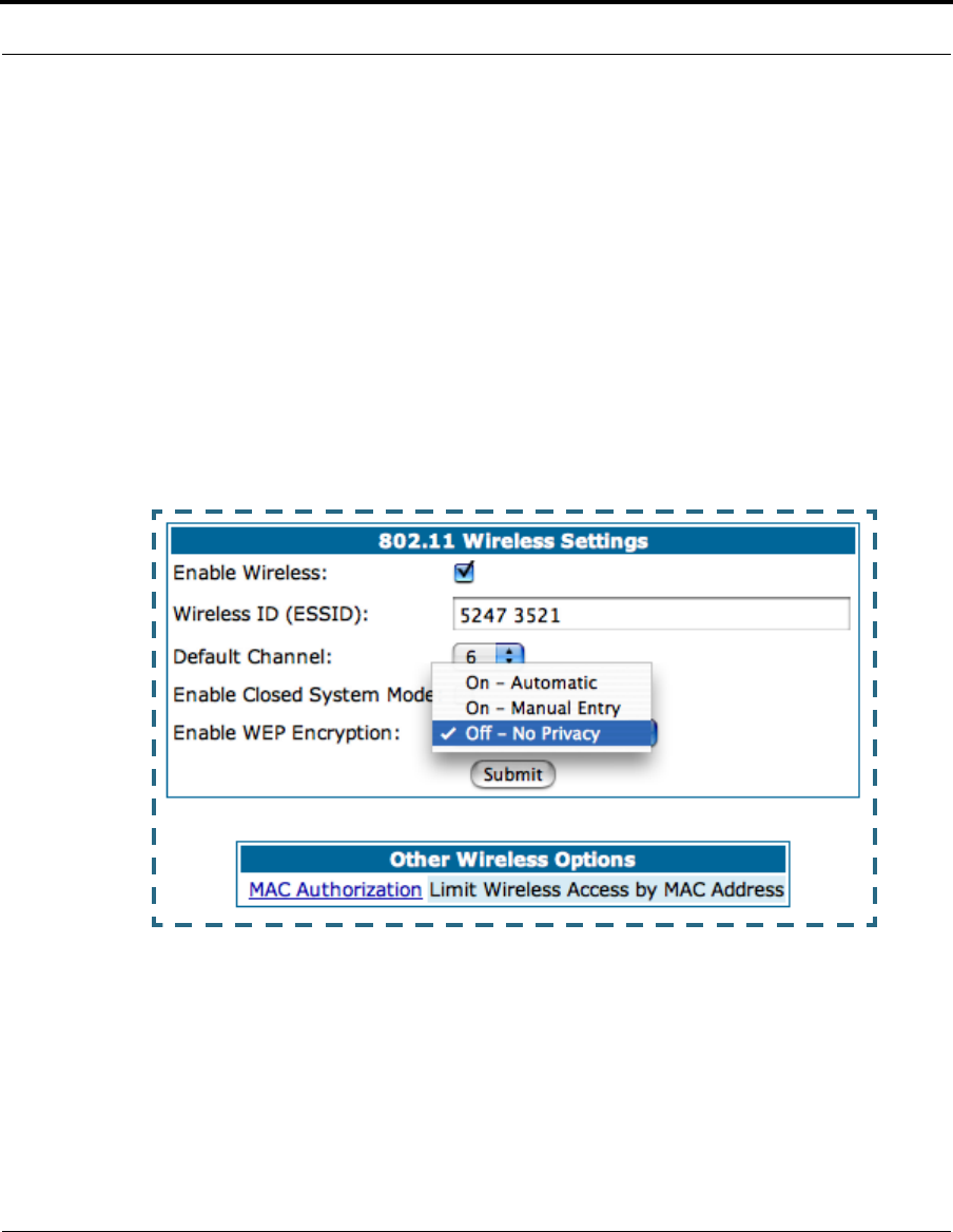
64
can enable 40-, 128-, or 256-bit WEP Encryption (depending on the capabil-
ity of your client wireless card) for IP traffic on your LAN.
You select a single key for encryption of outbound traffic. The WEP-enabled
client must have an identical key of the same length, in the identical slot (1
– 4) as the Gateway, in order to successfully receive and decrypt the traffic.
Similarly, the client also has a ‘default’ key that it uses to encrypt its trans-
missions. In order for the Gateway to receive the client’s data, it must like-
wise have the identical key of the same length, in the same slot. For
simplicity, a Gateway and its clients need only enter, share, and use the
first key.
You are strongly encouraged to enable WEP encryption on your wireless
LAN.
The pull-down menu for enabling WEP offers three settings: Off - No Pri-
vacy, On - Automatic, and On - Manual Entry.
•Off - No Privacy provides no encryption on your wireless LAN data.
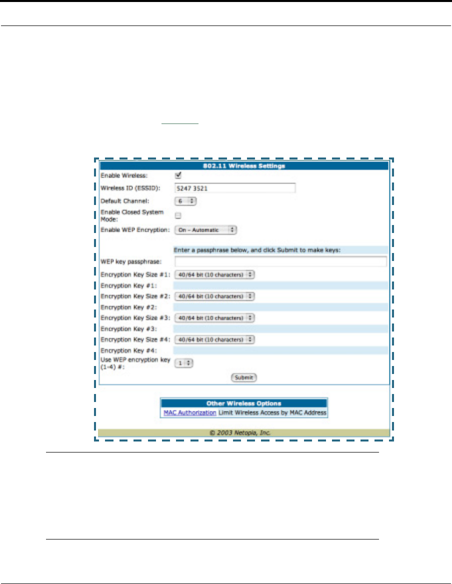
65
Configure
•On - Automatic is a passphrase generator. You enter a passphrase that
you choose in the WEP key passphrase field. The passphrase can be
any string of words or numbers.
When you click the
Submit
button, the software generates encryption
keys automatically.
☛ NOTE:
While clients may also have a passphrase feature, these are ven-
dor-specific and may not necessarily create the same keys. You
can passphrase generate a set of keys on one, and manually
enter them on the other to get around this.

66
Select the Encryption Key Size #1 – #4 from their respective pull-down
menus. The longer the key, the stronger the encryption and the more diffi-
cult it is to break the encryption.
Use WEP encryption key (1 – 4) # specifies which key the Gateway will
use to encrypt transmitted traffic. The default is key #1.
When you click the
Submit
button, the software generates encryption keys
automatically.
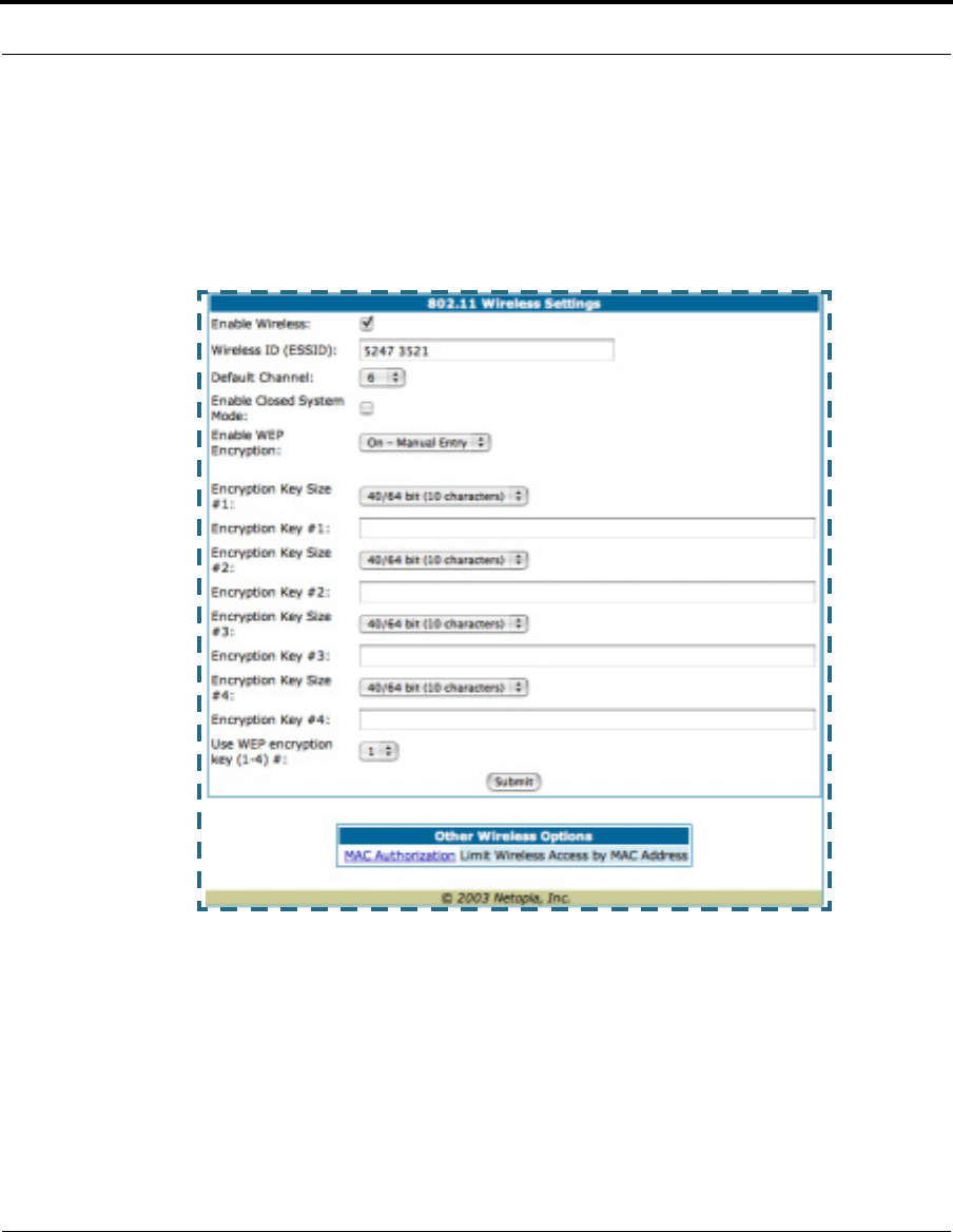
67
Configure
•On - Manual Entry allows you to enter your own encryption keys manu-
ally. This is a difficult process, but only needs to be done once. Avoid the
temptation to enter all the same characters.
Encryption Key Size #1 – #4: Selects the length of each encryption key.
The longer the key, the stronger the encryption and the more difficult it is to
break the encryption.
Encryption Key #1 – #4: The encryption keys. You enter keys using hexa-
decimal digits. For 40/64bit encryption, you need ten digits; 26 digits for
128bit, and 58 digits for 256bit WEP. Hexadecimal characters are 0 – 9,
and a – f.

68
Examples:
•40bit: 02468ACE02
•128bit: 0123456789ABCDEF0123456789
•256bit: 592CA140F0A238B0C61AE162F592CA140F0A238B0C61AE162F21A09C
Use WEP encryption key (1 – 4) #: Specifies which key the Gateway will
use to encrypt transmitted traffic. The default is key #1.
You disable the wireless LAN by unchecking the Enable Wireless checkbox,
clicking the
Submit
button, followed by the
Save and Restart
link.
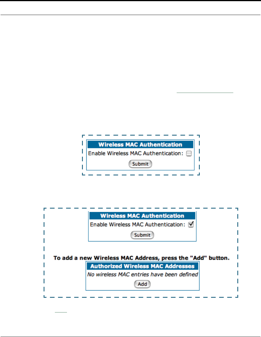
69
Configure
Wireless MAC Authentication: allows you to specify which client PCs are
allowed to join the wireless LAN by specific hardware address. Once it is
enabled, only entered MAC addresses that have been set to Allow will be
accepted onto the wireless LAN. All unlisted addresses will be blocked, in
addition to the listed addresses with Allow disabled.
To enable Wireless MAC Authentication, click the
MAC Authorization
link.
When the Wireless MAC Authentication screen appears, check the Enable
Wireless MAC Authentication checkbox:
The screen expands as follows:
Click the
Add
button. The Authorized Wireless MAC Address Entry
screen appears.
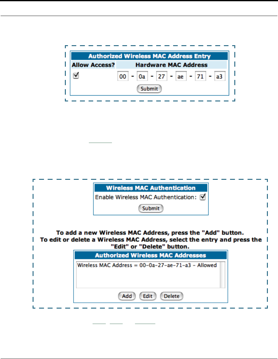
70
Enter the MAC (hardware) address of the client PC you want to authorize for
access to your wireless LAN. The Allow Access? checkbox is enabled by
default. Unchecking this checkbox specifically denies access from this MAC
address. Click the
Submit
button.
Your entry will be added to a list of authorized addresses as shown:
You can continue to
Add
,
Edit
, or
Delete
addresses to the list by clicking the
respective buttons.

71
Configure
After your first entry, the Alert icon will appear in the upper right cor-
ner of your screen. When you are finished adding addresses to the list, click
the Alert icon, and Save your changes and restart the Gateway.
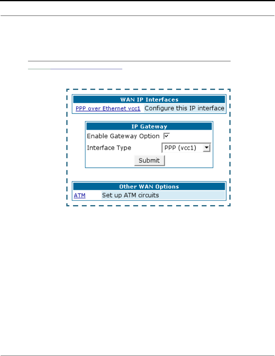
72
WAN
Link: Configure -> WAN
WAN IP Interfaces
Your IP interfaces are listed. Click on an interface to configure it.
IP Gateway
Enable Gateway: You can configure the Gateway to send packets to a
default gateway if it does not know how to reach the destination host.
Interface Type: If you have PPPoE enabled, you can specify that packets
destined for unknown hosts will be sent to the gateway being used by the
remote PPP peer. If you select ip-address, you must enter the IP address
of a host on a local or remote network to receive the traffic.
Default Gateway: The IP Address of the default gateway.
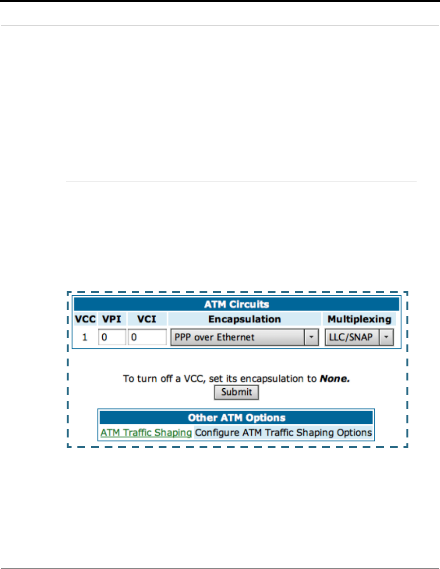
73
Configure
Other WAN Options
PPPoE: You can enable or disable PPPoE. This link also allows configura-
tion of NAT, admin restrictions, PPPoE username/password, and connec-
tion type.
ATM Circuits: You can configure the ATM circuits and the number of Ses-
sions. The IP Interface(s) should be reconfigured after making changes
here.
COS Version 7 supports VPI/VCI autodetection by default. If VPI/VCI
autodetection is enabled, the ATM Circuits page displays VPI/VCI = 0. If
you configure a new ATM VPI/VCI pair, upon saving and restarting, auto-
detection is disabled and only the new VPI/VCI pair configuration will be
enabled.
Available Encapsulation types: Available Multiplexing types:
PPP over Ethernet (PPPoE) LLC/SNAP
PPP over ATM (PPPoA) VC muxed
RFC-1483 Bridged Ethernet
RFC-1483 Routed IP
None
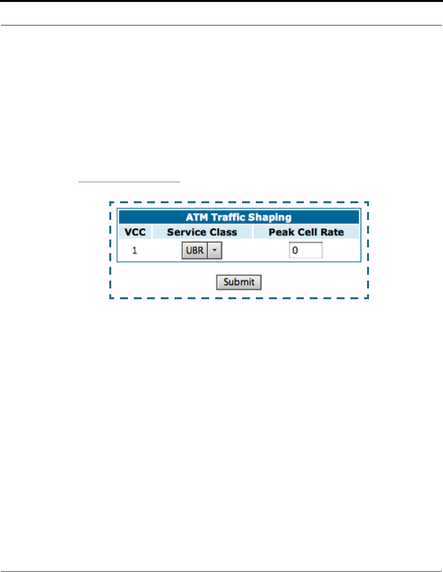
74
VPI/VCI Autodetection consists of eight static VPI/VCI pair configura-
tions. These are 0/35, 8/35, 0/32, 1/35, 8/32, 1/1, 1/32, 2/32.
These eight VPI/VCI pairs will be created if the Gateway is configured for
autodetection. If the Gateway does not train to any of these preconfig-
ured VPI/VCI pairs, then you can manually enter a VPI/VCI pair in the
ATM Circuits page.
ATM Traffic Shaping: You can prioritize delay-sensitive data by configur-
ing the Quality of Service (QoS) characteristics of the virtual circuit. Click
the
ATM Traffic Shaping
link.
You can choose UBR (Unspecified Bit Rate) or CBR (Constant Bit Rate)
from the pull-down menu and set the Peak Cell Rate (PCR) in the editable
field.
Unspecified Bit Rate (UBR) guarantees no minimum transmission rate.
Cells are transmitted on a “best effort” basis. However, there is a cap
on the maximum transmission rate for UBR VCs. In a practical situation:
• UBR VCs should be transmitted at a priority lower than CBR.
• Bandwidth should be shared equally among UBR VCs.
UBR applications are non real time traffic such as IP data traffic.
Constant Bit Rate (CBR) guarantees a certain transmission rate
(although the application may under utilize this bandwidth). A Peak Cell
Rate (PCR) characterizes CBR. CBR is most suited for real time applica-
tions such as real time voice / video. Although it can be used for other
applications.

75
Configure
Class PCR SCR MBS Transmit
Priority Comments
UBR X N/A N/A Low PCR is a cap
CBR X N/A N/A High PCR is a guaranteed rate
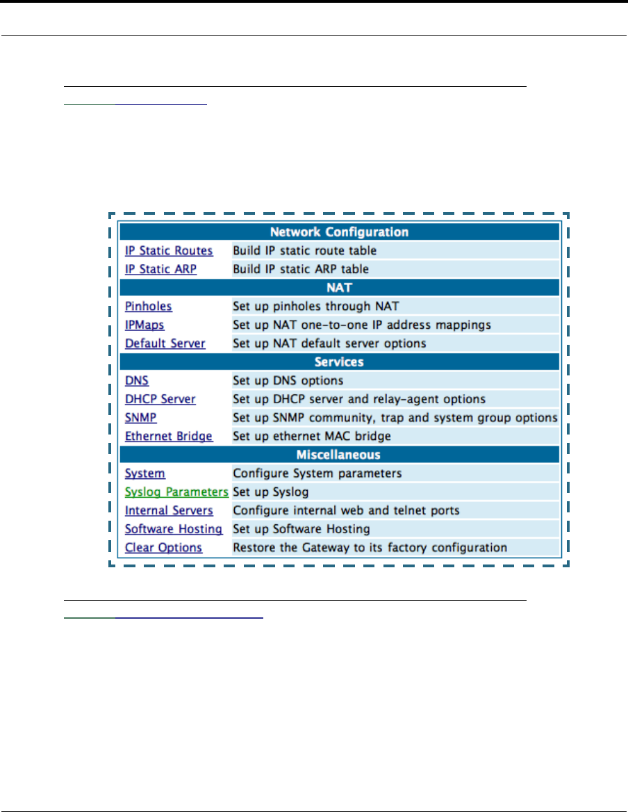
76
Link: Advanced
Selected Advanced options are discussed in the pages that follow. Many
are self-explanatory or are dictated by your service provider.
The following are links under Configure -> Advanced:
Link: IP Static Routes
A static route identifies a manually configured pathway to a remote network.
Unlike dynamic routes, which are acquired and confirmed periodically from
other routers, static routes do not time out. Consequently, static routes are
useful when working with PPP, since an intermittent PPP link may make
maintenance of dynamic routes problematic.
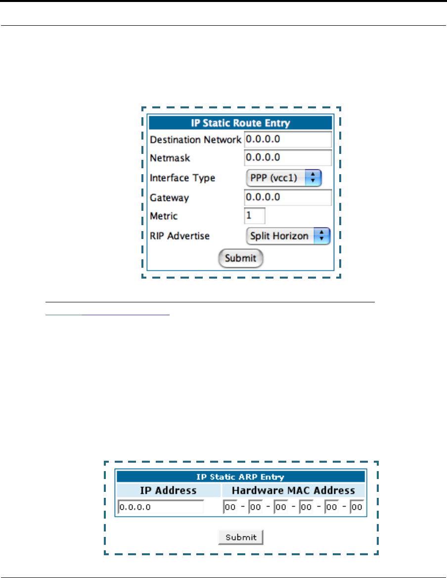
77
Configure
You can configure as many as 32 static IP routes for the Gateway.
Link: IP Static ARP
Your Gateway maintains a dynamic Address Resolution Protocol (ARP) table
to map IP addresses to Ethernet (MAC) addresses. It populates this ARP
table dynamically, by retrieving IP address/MAC address pairs only when it
needs them. Optionally, you can define static ARP entries to map IP
addresses to their corresponding Ethernet MAC addresses. Unlike dynamic
ARP table entries, static ARP table entries do not time out. The IP address
cannot be 0.0.0.0. The Ethernet MAC address entry is in nn-nn-nn-nn-nn-nn
(hexadecimal) format.
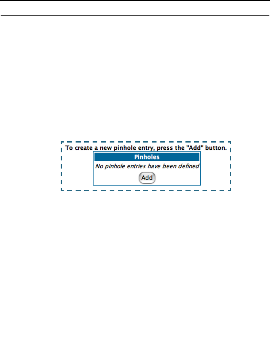
78
Link: Pinholes
Pinholes allow you to transparently route selected types of network traffic,
such as FTP requests or HTTP (Web) connections, to a specific host behind
the Gateway. Creating a pinhole allows access traffic originating from a
remote connection (WAN) to be sent to the internal computer (LAN) that is
specified in the Pinhole page.
Pinholes are common for applications like multiplayer online games. Refer
to software manufacturer application documentation for specific traffic
types and port numbers.
Configure Specific Pinholes. Planning for Your Pinholes. Determine if
any of the service applications that you want to provide on your LAN sta-
tions use TCP or UDP protocols. If an application does, then you must con-
figure a pinhole to implement port forwarding. This is accessed from the
Advanced -> Pinholes page.
Example: A LAN Requiring Three Pinholes . The procedure on the fol-
lowing pages describes how you set up your NAT-enabled Cayman Gateway
to support three separate applications. This requires passing three kinds of
specific IP traffic through to your LAN.
Application 1
: You have a Web server located on your LAN behind your Cay-
man Gateway and would like users on the Internet to have access to it. With
NAT “On”, the only externally visible IP address on your network is the Gate-

79
Configure
way’s WAN IP (supplied by your Service Provider). All traffic intended for that
LAN Web server must be directed to that IP address.
Application 2
: You want one of your LAN stations to act as the “central
repository” for all email for all of the LAN users.
Application 3
: One of your LAN stations is specially configured for game
applications. You want this specific LAN station to be dedicated to games.
A sample table to plan the desired pinholes is:
For this example, Internet protocols TCP and UDP must be passed through
the NAT security feature and the Gateway’s embedded Web (HTTP) port
must be re-assigned by configuring new settings on the Internal Servers
page.
☛ TIPS for making Pinhole Entries:
1. If the port forwarding feature is required for Web services,
ensure that the embedded Web server’s port number is re-
assigned PRIOR to any Pinhole data entry.
2. Enter data for one Pinhole at a time.
3. Use a unique name for each Pinhole. If you choose a duplicate
name, it will overwrite the previous information without warning.
WAN Traffic Type Protocol Pinhole Name LAN Internal IP
Address
Web TCP my-webserver 192.168.1.1
Email TCP my-mailserver 192.168.1.2
Games UDP my-games 192.168.1.3
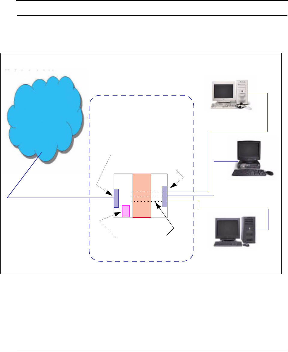
80
A diagram of this LAN example is:
You can also use the LAN-side address of the Gateway, 192.168.1.x:8100
to access the web and 192.168.1.x:23 to access the telnet server.
WAN
LAN
Ethernet
Interface
192.168.1.1
192.168.1.2
192.168.1.3
my-webserver
my-mailserver
my-games
Gateway
NAT
NAT Pinholes
Embedded
Web Server
210.219.41.20
210.219.41.20:8100
Ethernet
Interface
Internet
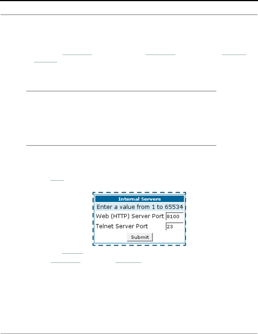
81
Configure
Pinhole Configuration Procedure. Use the following steps:
1. From the
Configure
toolbar button ->
Advanced
link, select the
Internal
Servers
link.
Since Port Forwarding is required for this example, the Cayman embed-
ded Web server is configured first.
☛ NOTE:
The two text boxes, Web (HTTP) Server Port and Telnet Server
Port, on this page refer to the port numbers of the Cayman Gate-
way’s embedded administration ports.
To pass Web traffic through to your LAN station(s), select a Web (HTTP) Port
number that is greater than 1024. In this example, you choose 8100.
2. Type
8100
in the Web (HTTP) Server Port text box.
3. Click the
Submit
button.
4. Click
Advanced
. Select the
Pinholes
link to go to the Pinhole page.
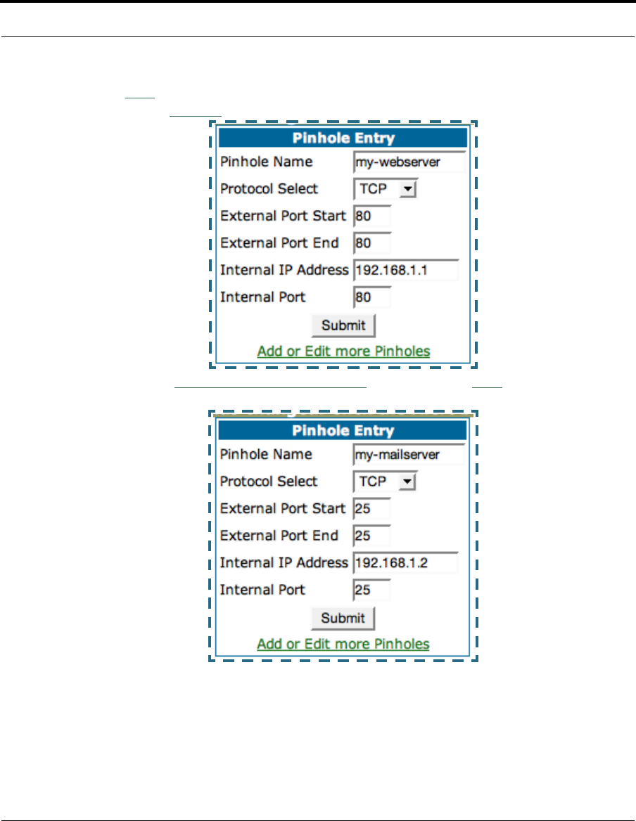
82
5. Click
Add
. Type your specific data into the Pinhole Entries table of this
page. Click
Submit
.
6. Click on the
Add or Edit more Pinholes
link. Click the
Add
button. Add the
next Pinhole. Type the specific data for the second Pinhole.
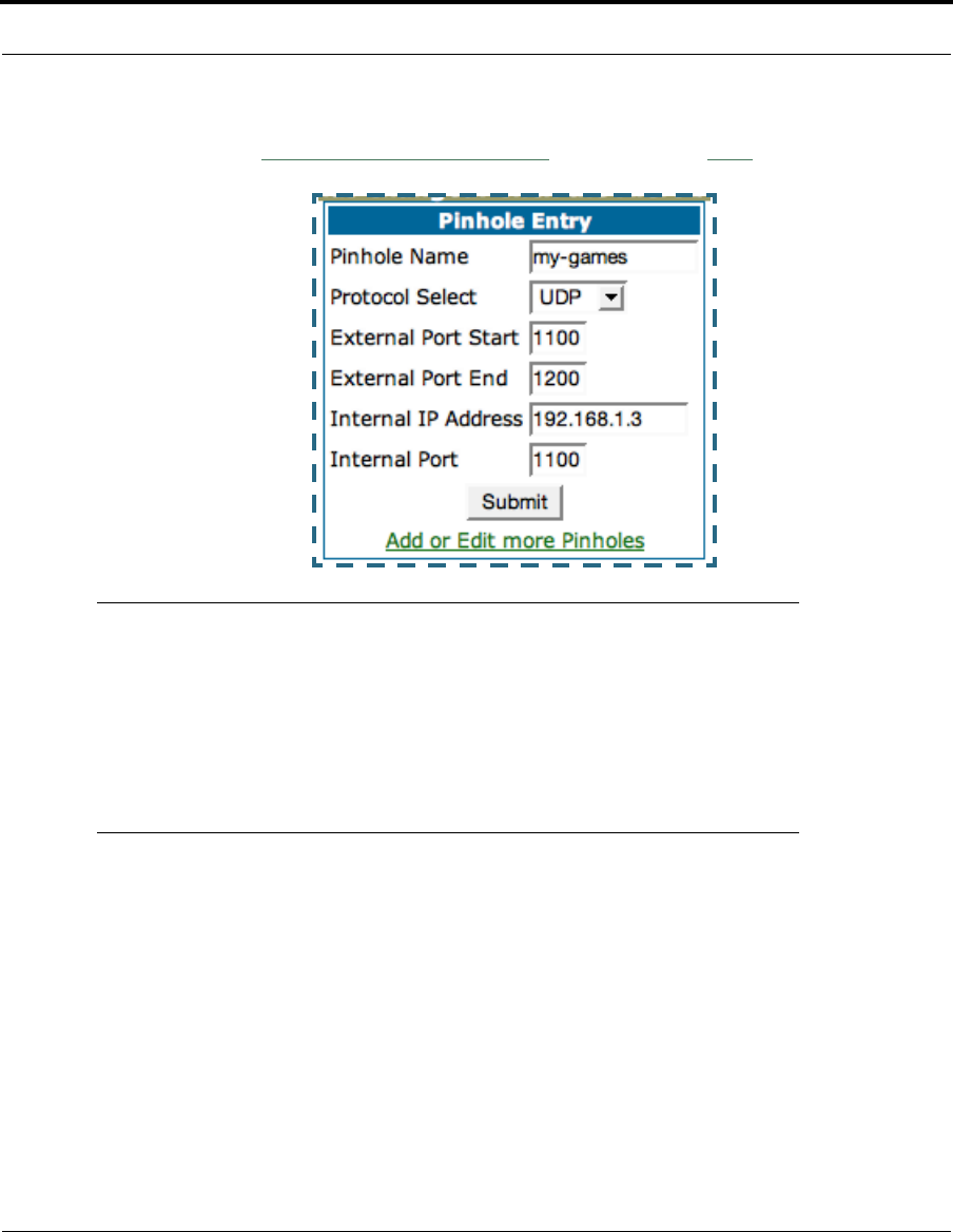
83
Configure
7. Click on the
Add or Edit more Pinholes
link. Click the
Add
button. Add the
next Pinhole. Type the specific data for the third Pinhole.
☛ NOTE:
Note the following parameters for the “my-games” Pinhole:
1. The Protocol ID is UDP.
2. The external port is specified as a range.
3. The Internal port is specified as the lower range entry.
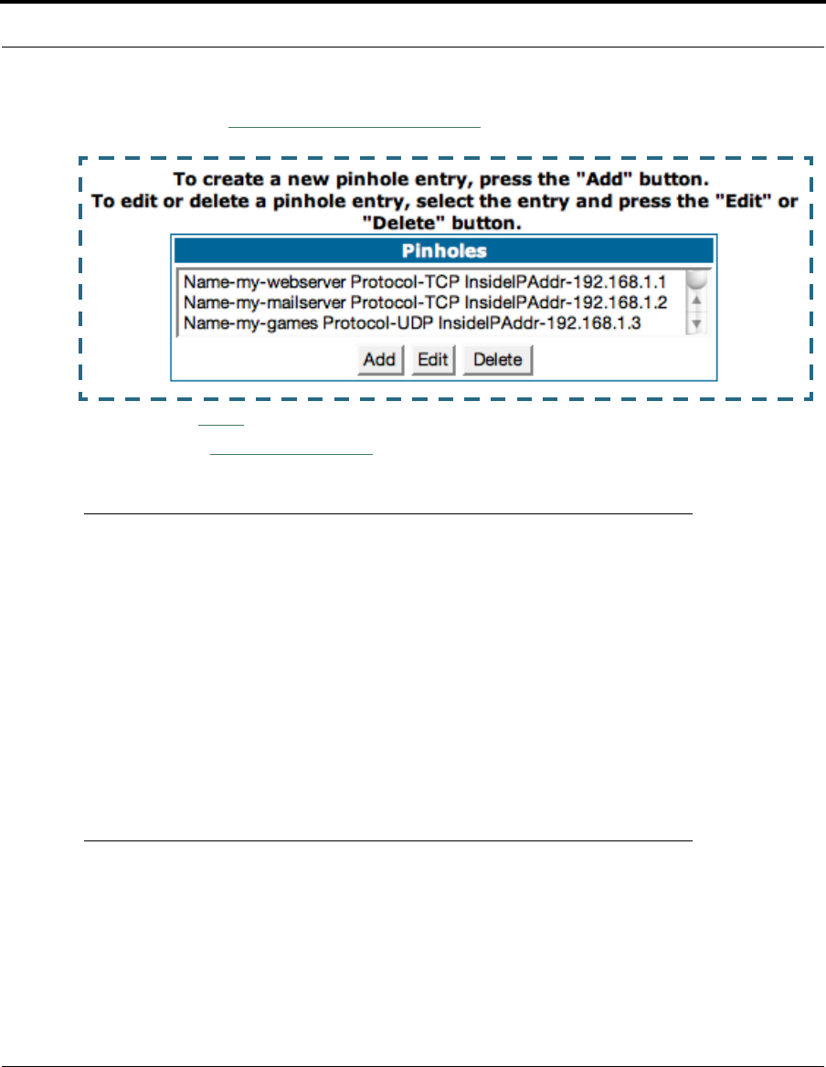
84
8. Click on the
Add or Edit more Pinholes
link. Review your entries to be
sure they are correct.
9. Click the
Alert
button.
10. Select the
Save and Restart
link to complete the entire Pinhole creation
task and ensure that the parameters are properly saved.
☛ NOTE:
REMEMBER: When you have re-assigned the port address for the
embedded Web server, you can still access this facility.
Use the Gateway’s WAN address plus the new port number.
In this example it would be
<WAN Gateway address>:<new port number> or, in this case,
210.219.41.20:8100
You can also use the LAN-side address of the Gateway,
192.168.1.x:8100 to access the web and 192.168.1.x:23 to
access the telnet server.
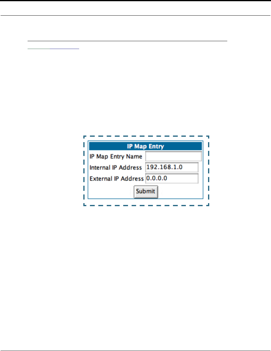
85
Configure
Link: IPMaps
IPMaps supports one-to-one Network Address Translation (NAT) for IP
addresses assigned to servers, hosts, or specific computers on the LAN
side of the Cayman Gateway.
A single static or dynamic (DHCP) WAN IP address must be assigned to sup-
port other devices on the LAN. These devices utilize Cayman’s default NAT/
PAT capabilities.
Configure the IPMaps Feature
FAQs for the IPMaps Feature
Before configuring an example of an IPMaps-enabled network, review these
frequently asked questions.
What are IPMaps and how are they used? The IPMaps feature allows
multiple static WAN IP addresses to be assigned to the Cayman Gateway.
Static WAN IP addresses are used to support specific services, like a web
server, mail server, or DNS server. This is accomplished by mapping a sep-
arate static WAN IP address to a specific internal LAN IP address. All traffic
arriving at the Gateway intended for the static IP address is transferred to

86
the internal device. All outbound traffic from the internal device appears to
originate from the static IP address.
Locally hosted servers are supported by a public IP address while LAN
users behind the NAT-enabled IP address are protected.
IPMaps is compatible with the use of NAT, with either a statically assigned
IP address or DHCP/PPP served IP address for the NAT table.
What types of servers are supported by IPMaps? IPMaps allows a Cay-
man Gateway to support servers behind the Gateway, for example, web,
mail, FTP, or DNS servers. VPN servers are not supported at this time.
Can I use IPMaps with my PPPoE or PPPoA connection? Yes. IPMaps
can be assigned to the WAN interface provided they are on the same
subnet. Service providers will need to ensure proper routing to all IP
addresses assigned to your WAN interface.
Will IPMaps allow IP addresses from different subnets to be assigned
to my Gateway? IPMap will support statically assigned WAN IP addresses
from the same subnet.
WAN IP addresses from different subnets are not supported.
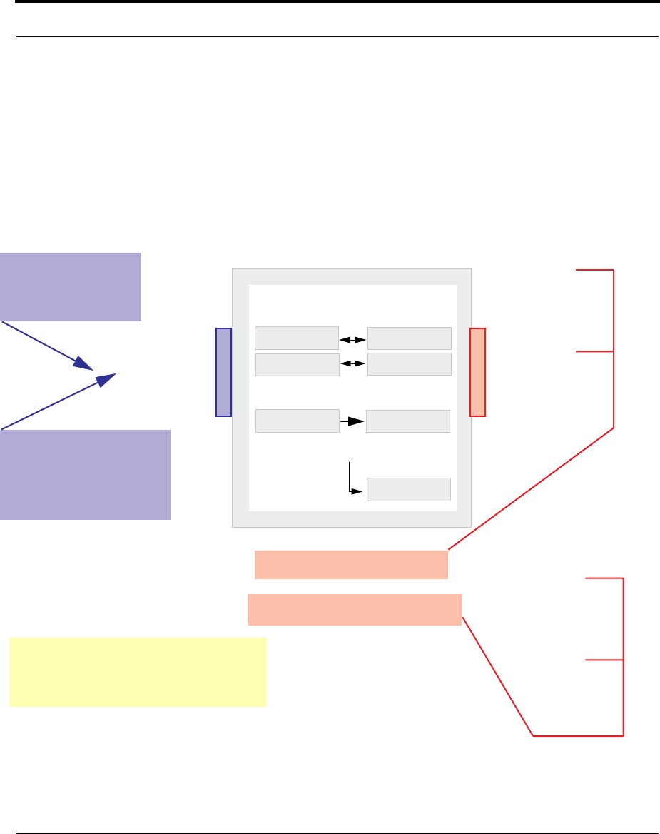
87
Configure
IPMaps Block Diagram
The following diagram shows the IPMaps principle in conjunction with exist-
ing Cayman NAT operations:
NAT/PAT Table
143.137.50.37
143.137.50.36
143.137.50.35
192.168.1.1
192.168.1.n
192.168.1.3
192.168.1.2
...
...
Cayman Gateway
Static IP Addresses
for IPMaps Applications
143.137.50.37
143.137.50.36
143.137.50.35
Static IP Addresses
or
DHCP/PPP Served IP Address
for Cayman’s default NAT/PAT
Capabilities
IPMaps:
One-to-One
Multiple Address Mapping
LAN stations with WAN IP traffic
forwarded by Cayman’s IPMaps
LAN stations with WAN IP traffic
forwarded by Cayman’s NAT function.
WAN Interface LAN Interface
192.168.1.1
192.168.1.2
192.168.1.3
192.168.1.n
.
.
.
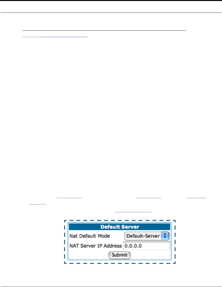
88
Link: Default Server
This feature allows you to:
•Direct your Gateway to forward all externally initiated IP traffic (TCP and
UDP protocols only) to a default host on the LAN.
• Enable it for certain situations:
– Where you cannot anticipate what port number or packet protocol an
in-bound application might use. For example, some network games
select arbitrary port numbers when a connection is opened.
– When you want all unsolicited traffic to go to a specific LAN host.
•Configure for IP Passthrough.
Configure a Default Server. This feature allows you to direct unsolicited
or non-specific traffic to a designated LAN station. With NAT “On” in the
Gateway, these packets normally would be discarded.
For instance, this could be application traffic where you don’t know (in
advance) the port or protocol that will be used. Some game applications fit
this profile.
Use the following steps to setup a NAT default server to receive this infor-
mation:
1. Select the
Configure
toolbar button, then
Advanced
, then the
Default
Server
link.
2. From the pull-down menu, select
Default-Server
. The NAT Server IP
Address field appears.

89
Configure
3. Determine the IP address of the LAN computer you have chosen to
receive the unexpected or unknown traffic.
Enter this address in the NAT Server IP Address field.
4. Click the
Submit
button.
5. Click the
Alert
button.
6. Click the
Save and Restart
link to confirm.
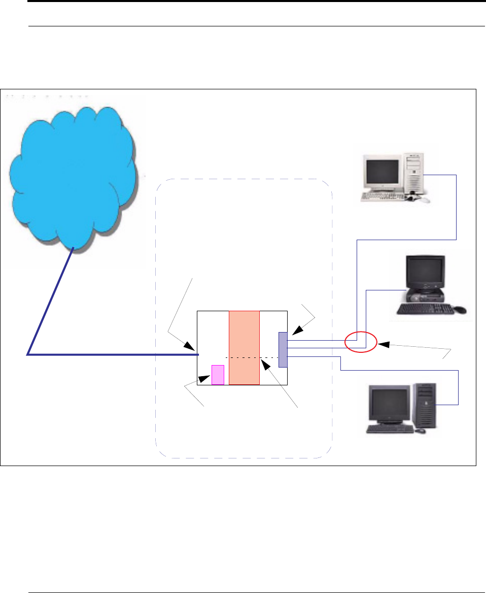
90
Typical Network Diagram. A typical network using the NAT Default Server
looks like this:
You can also use the LAN-side address of the Gateway, 192.168.1.x to
access the web and telnet server.
WAN
LAN
Ethernet
Interface
192.168.1.3
192.168.1.2
192.168.1.1
LAN STN #3
LAN STN #2
NAT Default Server
Gateway
NAT
NAT Pinhole
Embedded
Web Server
210.219.41.20
210.219.41.20
(Port 80 default)
NAT protected
Ethernet
Interface
Internet

91
Configure
NAT Combination Application. Cayman’s NAT security feature allows you
to configure a sophisticated LAN layout that uses both the Pinhole and
Default Server capabilities.
With this topology, you configure the embedded administration ports as a
first task, followed by the Pinholes and, finally, the NAT Default Server.
When using both NAT pinholes and NAT Default Server the Gateway works
with the following rules (in sequence) to forward traffic from the Internet to
the LAN:
1. If the packet is a response to an existing connection created by outbound
traffic from a LAN PC, forward to that station.
2. If not, check for a match with a pinhole configuration and, if one is found,
forward the packet according to the pinhole rule.
3. If there’s no pinhole, the packet is forwarded to the Default Server.
IP-Passthrough. COS Version 7 now offers an IP passthrough feature. The
IP passthrough feature allows a single PC on the LAN to have the Gateway’s
public address assigned to it. It also provides PAT (NAPT) via the same pub-
lic IP address for all other hosts on the private LAN subnet. Using IP
passthrough:
•The public WAN IP is used to provide IP address translation for private
LAN computers.
•The public WAN IP is assigned and reused on a LAN computer.
•DHCP address serving can automatically serve the WAN IP address to a
LAN computer.
When DHCP is used for addressing the designated passthrough PC, the
acquired or configured WAN address is passed to DHCP, which will
dynamically configure a single-servable-address subnet, and reserve the
address for the configured MAC address. This dynamic subnet configura-
tion is based on the local and remote WAN address and subnet mask. If
the WAN interface does not have a suitable subnet mask that is usable,
for example when using PPP or PPPoE, the DHCP subnet configuration
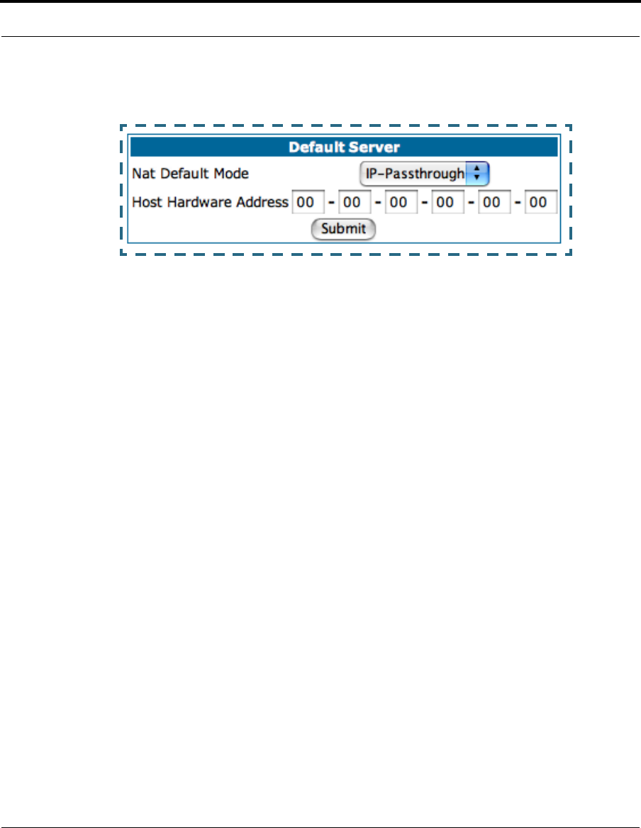
92
will default to a class C subnet mask.
If you select IP-Passthrough the Host Hardware Address field displays.
Here you enter the MAC address of the designated IP-Passthrough com-
puter.
•If this MAC address is not all zeroes, then it will use DHCP to set the LAN
host's address to the (configured or acquired) WAN IP address.
The MAC address must be six colon-delimited or dash-delimited sets of
hex digits ('0' – 'FF').
•If the MAC address is all zeroes, then the LAN host will have to be config-
ured manually.
Once configured, the passthrough host's DHCP leases will be shortened to
two minutes. This allows for timely updates of the host's IP address, which
will be a private IP address before the WAN connection is established. After
the WAN connection is established and has an address, the passthrough
host can renew its DHCP address binding to acquire the WAN IP address.
A restriction. Since both the Gateway and the passthrough host will use
the same IP address, new sessions that conflict with existing sessions will
be rejected by the Gateway. For example, suppose you are a teleworker
using an IPSec tunnel from the Gateway and from the passthrough host.
Both tunnels go to the same remote endpoint, such as the VPN access con-
centrator at your employer’s office. In this case, the first one to start the
IPSec traffic will be allowed; the second one – since, from the WAN, it's
indistinguishable – will fail.
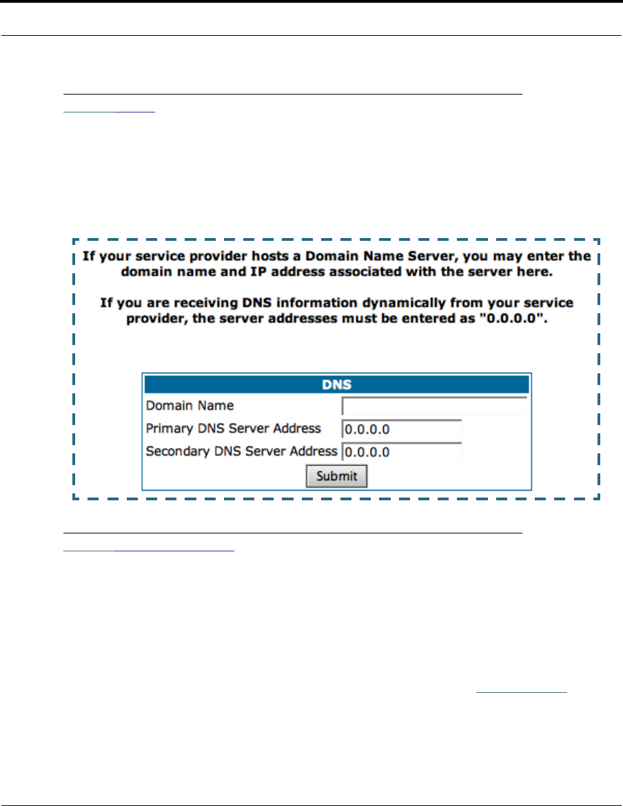
93
Configure
Link: DNS
Your Service Provider may maintain a Domain Name server. If you have the
information for the DNS servers, enter it on the DNS page. If your Gateway
is configured to use DHCP to obtain its WAN IP address, the DNS informa-
tion is automatically obtained from that same DHCP Server.
Link: DHCP Server
Your Gateway can provide network configuration information to computers
on your LAN, using the Dynamic Host Configuration Protocol (DHCP).
If you already have a DHCP server on your LAN, you should turn this service
off.
If you want the Gateway to provide this service, click the
Server Mode
pull-
down menu, then configure the range of IP addresses that you would like
the Gateway to hand out to your computers.
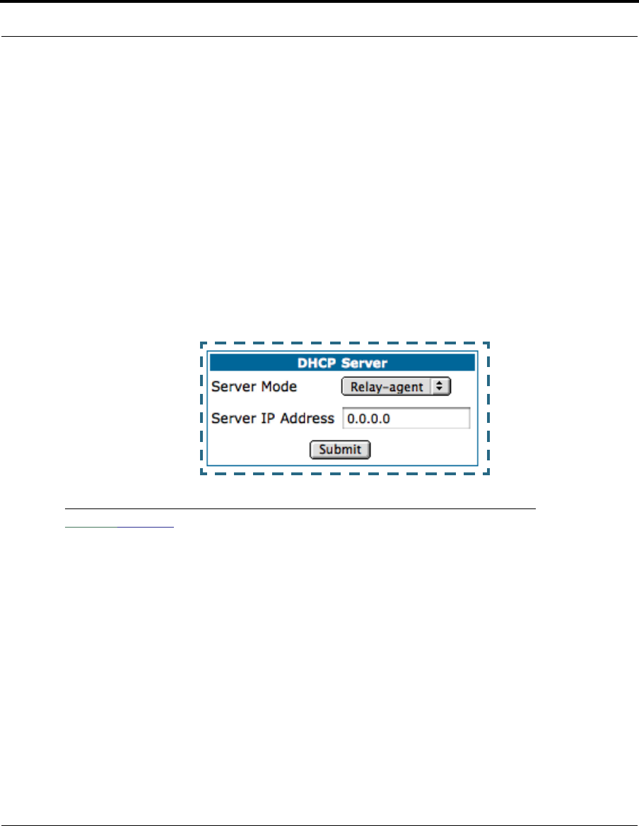
94
You can also specify the length of time the computers can use the configu-
ration information; DHCP calls this period the lease time.
Your Service Provider may, for certain services, want to provide configura-
tion from its DHCP servers to the computers on your LANs. In this case, the
Gateway will relay the DHCP requests from your computers to a DHCP
server in the Service Provider's network.
Click the relay-agent and enter the IP address of the Service Provider's
DHCP server in the Server Address field. This address is furnished by the
Service Provider.
Link: SNMP
The Simple Network Management Protocol (SNMP) lets a network adminis-
trator monitor problems on a network by retrieving settings on remote net-
work devices. The network administrator typically runs an SNMP
management station program on a local host to obtain information from an
SNMP agent. In this case, the Cayman Gateway is an SNMP agent.
You enter SNMP configuration information on this page.
Your network administrator furnishes the SNMP parameters.
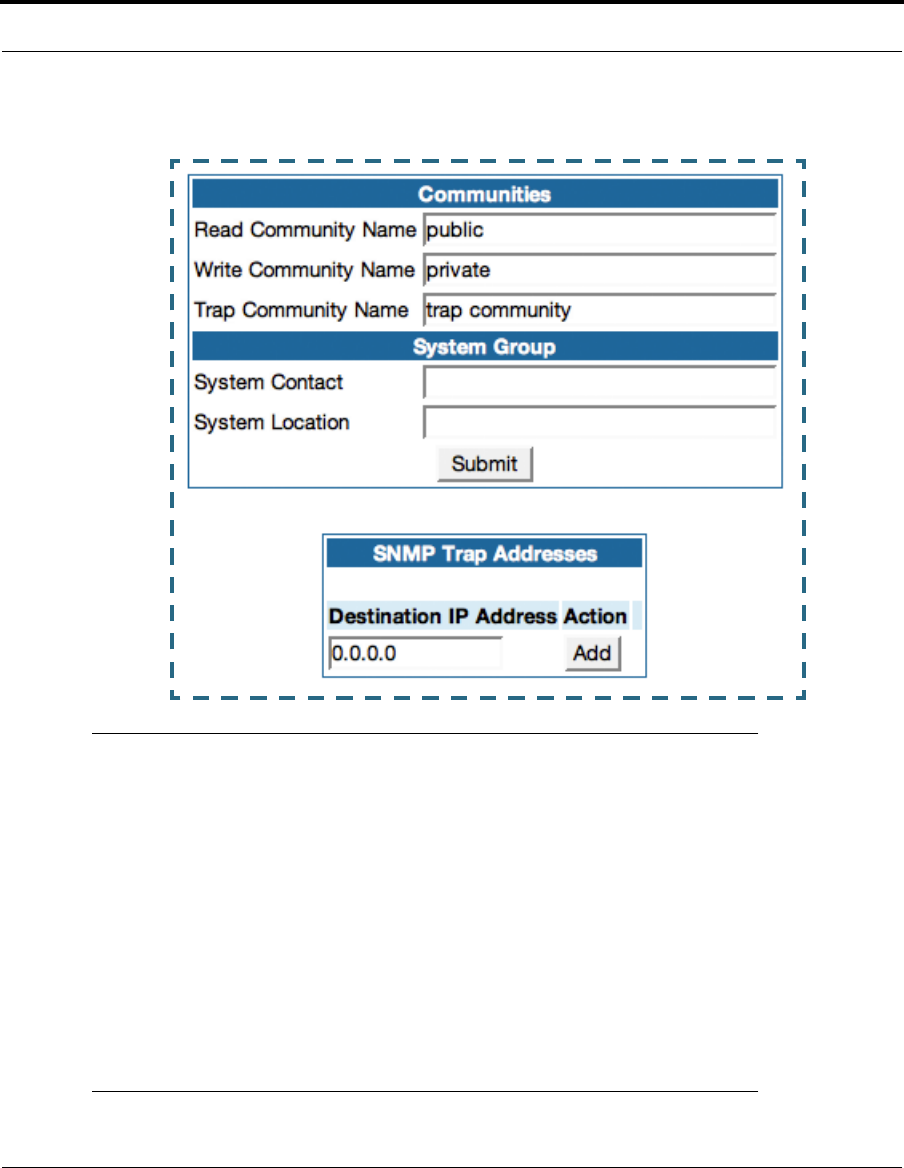
95
Configure
☛ WARNING:
SNMP presents you with a security issue. The community
facility of SNMP behaves somewhat like a password. The
community “public” is a well-known community name. It
could be used to examine the configuration of your Gateway
by your service provider or an uninvited reviewer. While
Cayman's SNMP implementation does not allow changes to
the configuration, the information can be read from the
Gateway.
If you are strongly concerned about security, you may
delete the “public” community.

96
Link: Advanced -> Ethernet Bridge
The Cayman Gateway can be used as a bridge, rather than a router. A
bridge is a device that joins two networks. As an Internet access device, a
bridge connects the home computer directly to the service provider’s net-
work equipment with no intervening routing functionality, such as Network
Address Translation. Your home computer becomes just another address
on the service provider’s network. In a DSL connection, the bridge serves
simply to convey the digital data information back and forth over your tele-
phone lines in a form that keeps it separate from your voice telephone sig-
nals.
If your service provider’s network is set up to provide your Internet connec-
tivity via bridge mode, you can set your Cayman Gateway to be compatible.
Bridges let you join two networks, so that they appear to be part of the
same physical network. As a bridge for protocols other than TCP/IP, your
Gateway keeps track of as many as 512 MAC (Media Access Control)
addresses, each of which uniquely identifies an individual host on a net-
work. Your Gateway uses this bridging table to identify which hosts are
accessible through which of its network interfaces. The bridging table con-
tains the MAC address of each packet it sees, along with the interface over
which it received the packet. Over time, the Gateway learns which hosts are
available through its WAN port and/or its LAN port.
When configured in Bridge Mode, the Cayman will act as a pass-through
device and allow the workstations on your LAN to have public addresses
directly on the internet.
☛ NOTE:
In this mode the Cayman is providing NO firewall protection as is
afforded by NAT. Also, only the workstations that have a public
address can access the internet. This can be useful if you have
multiple static public IPs on the LAN.
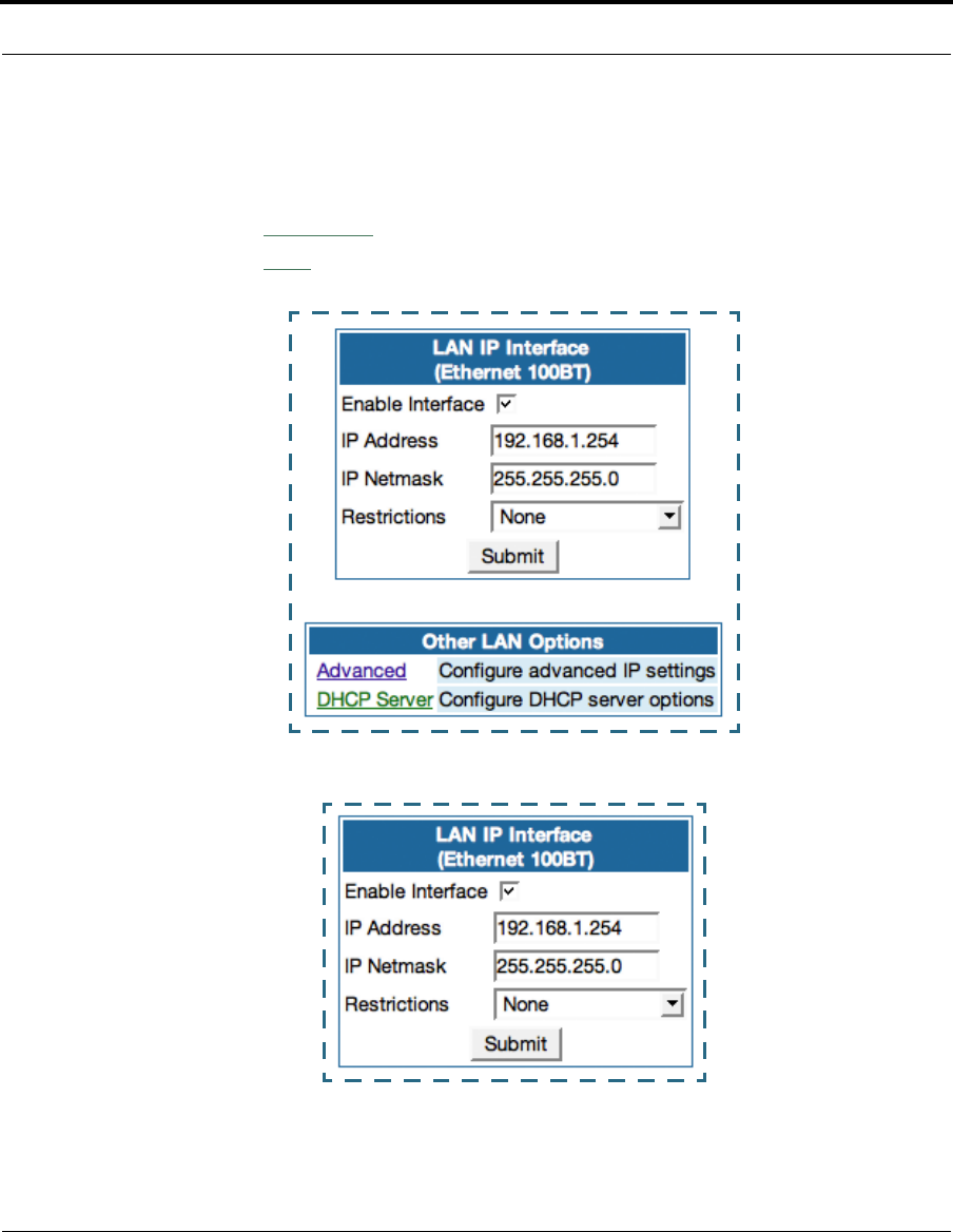
97
Configure
Configuring for Bridge Mode
1. Browse into the Cayman Gateway’s web interface.
2. Click on the
Configure
button in the upper Menu bar.
3. Click on the
LAN
link.
The LAN page appears.
4. In the box titled LAN IP Interface (Ethernet 100BT):
a. Check the Enable Interface selection.
*Make note of the Ethernet IP Address and subnet mask.
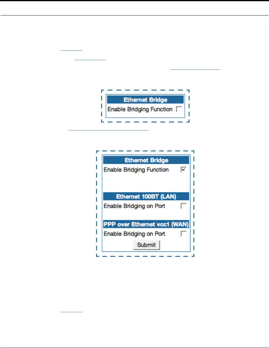
98
You can use this address to access the router in the future.
b. Click
Submit
.
5. Click on the
Advanced
link in the left-hand links toolbar.
6. Under the heading of Services, click on the
Ethernet Bridge
link.
The Ethernet Bridge page appears.
7. Check the
Enable Bridging Function
selection.
The window expands.
8. Under Ethernet 100BT (LAN):
Check the Enable Bridging on Port selection.
9. Under RFC-1483 Bridged Ethernet vcc1 (WAN), or under PPP over Ether-
net vcc1 (WAN) [as per your configuration]:
a. Check the Enable Bridging on Port selection.
b. Click
Submit
.
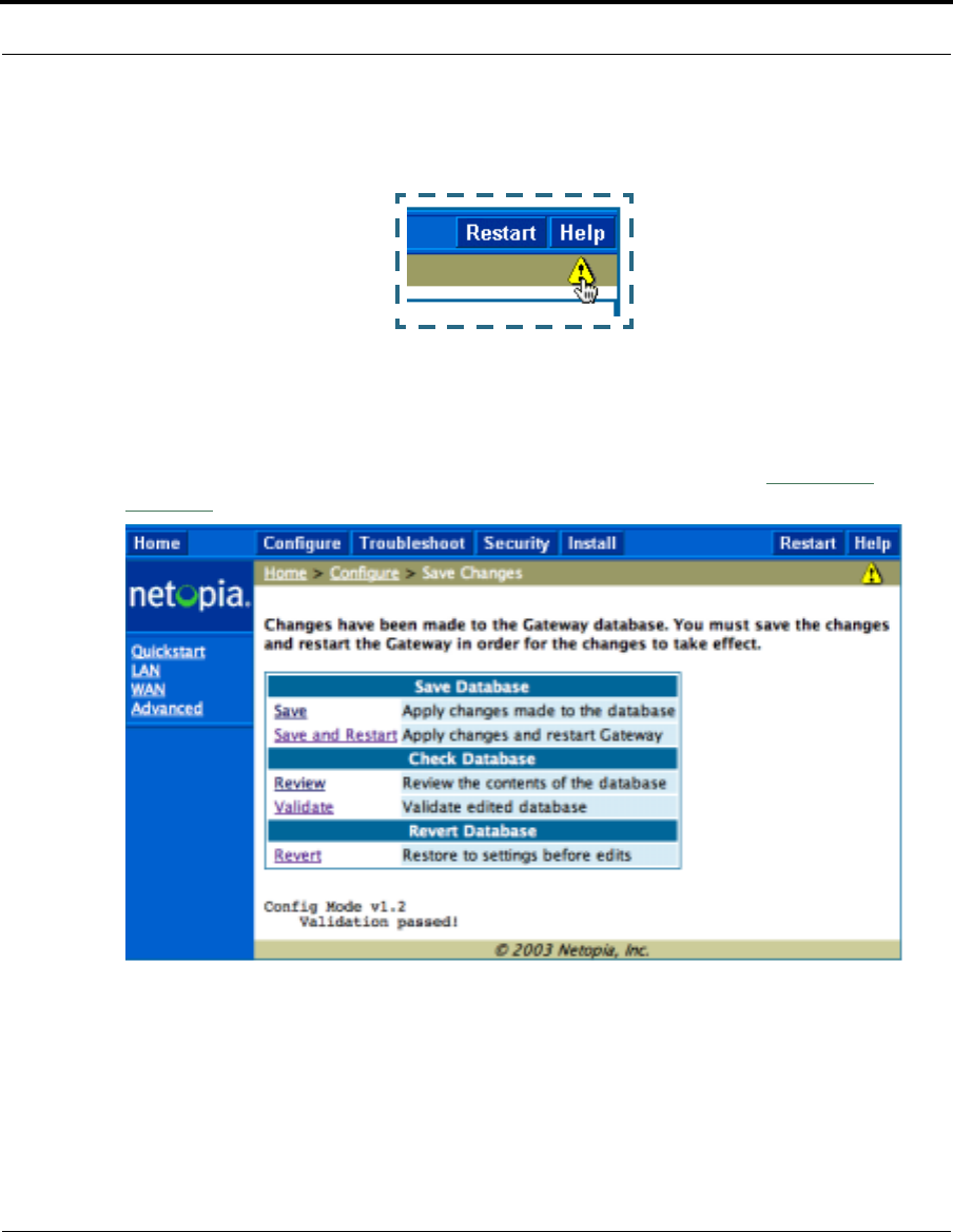
99
Configure
10. At this point you should be ready to do the final save on the configuration
changes you have made.
The yellow Alert symbol will show up underneath the Help button on the
right-hand end on the menu bar.
11. Click on this symbol and you will see whether your changes have been
verified.
12. If you are satisfied with the changes you have made, click
Save and
Restart
in the Save Database box to Apply changes and restart Gateway.
You have now configured your Cayman Gateway for bridging, and it will
bridge all traffic across the WAN. You will need to make configurations to
your machines on your LAN. These settings must be made in accordance
with your ISP. If you ever need to get back into the Cayman Gateway again
for management reasons, you will need to manually configure your machine
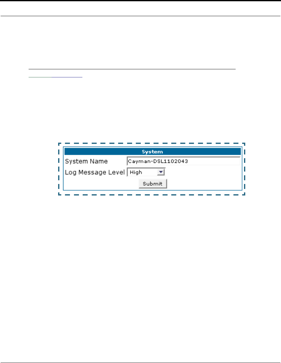
100
to be in the same subnet as the Ethernet interface of the Cayman, since
DHCP server is not operational in bridge mode.
Link: System
The System Name defaults to your Gateway's factory identifier combined
with its serial number. Some cable-oriented Service Providers use the Sys-
tem Name as an important identification and support parameter. If your
Gateway is part of this type of network, do NOT alter the System Name
unless specifically instructed by your Service Provider.
The System Name can be 1-63 characters long; it can include embedded
spaces and special characters.
The Log Message Level alters the severity at which messages are col-
lected in the Gateway's system log. Do not alter this field unless instructed
by your Support representative.
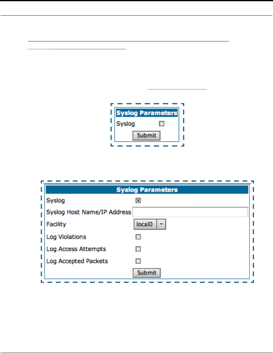
101
Configure
Link: Syslog Parameters
You can configure a UNIX-compatible syslog client to report a number of
subsets of the events entered in the Gateway’s WAN Event History. Syslog
sends log-messages to a host that you specify.
To enable syslog logging, click on the
Syslog Parameters
link.
Check the Syslog checkbox. The screen expands.
•Syslog: Enable syslog logging in the system.
•Syslog Host Name/IP Address: Enter the name or the IP Address of
the host that should receive syslog messages.

102
•Facility: From the pull-down menu, select the Syslog facility to be used
by the router when generating syslog messages. Options are local0
through local7.
•Log Violations: If you check this checkbox, the Gateway will generate
messages whenever a packet is discarded because it violates the
router's security policy.
•Log Access Attempts: If you check this checkbox, the Gateway will gen-
erate messages whenever a packet attempts to access the router or
tries to pass through the router. This option is disabled by default.
•Log Accepted Packets: If you check this checkbox, the Gateway will
generate messages whenever a packet accesses the router or passes
through the router. This option is disabled by default.
Syslog messages generated by the Gateway may display the following rea-
sons:
1. permitted 8. dropped - fragmented
packet 15. TCP SYN flood detected
2. attempt 9. dropped - cannot fragment 16. Telnet receive DoS attack
- packets dropped
3. administrative access
authenticated and allowed 10. dropped - no route found 17. administrative access
denied - telnet access not
allowed
4. administrative access
allowed 11. dropped - possible land
attack 18. administrative access
denied - invalid user name
5. dropped - violation of secu-
rity policy 12. dropped – reassembly
timeout 19. administrative access
denied - invalid password
6. dropped - invalid check-
sum 13. dropped – illegal size 20. administrative access
denied - web access not
allowed
7. dropped - invalid data
length 14. dropped - invalid IP ver-
sion 21. administrative access
attempted
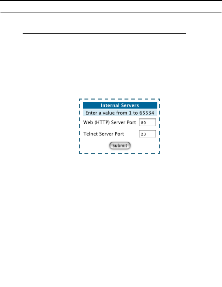
103
Configure
Link: Internal Servers
Your Gateway ships with an embedded Web server and support for a Telnet
session, to allow ease of use for configuration and maintenance. The
default ports of 80 for HTTP and 23 for Telnet may be reassigned. This is
necessary if a pinhole is created to support applications using port 80 or
23. See “Pinholes” on page 78. for more information on Pinhole configura-
tion.
Web (HTTP) Server Port: To reassign the port number used to access the
Cayman embedded Web server, change this value to a value greater than
1024. When you next access the embedded Cayman Web server, append
the IP address with <port number>, (e.g. Point your browser to http://
210.219.41.20:8080).
Telnet Server Port: To reassign the port number used to access your Cay-
man embedded Telnet server, change this value to a value greater than
1024. When you next access the Cayman embedded Telnet server, append
the IP address with <port number>, (e.g. telnet 210.219.41.20 2323).
You can also use the LAN-side address of the Gateway, 192.168.1.x:8100
to access the web server and 192.168.1.x:2323 to access the telnet
server. The value of 0 for an internal server port will disable that server.
You can disable Telnet or Web, but not both. If you disabled both ports, you
would not be able to reconfigure the unit without pressing the reset button.
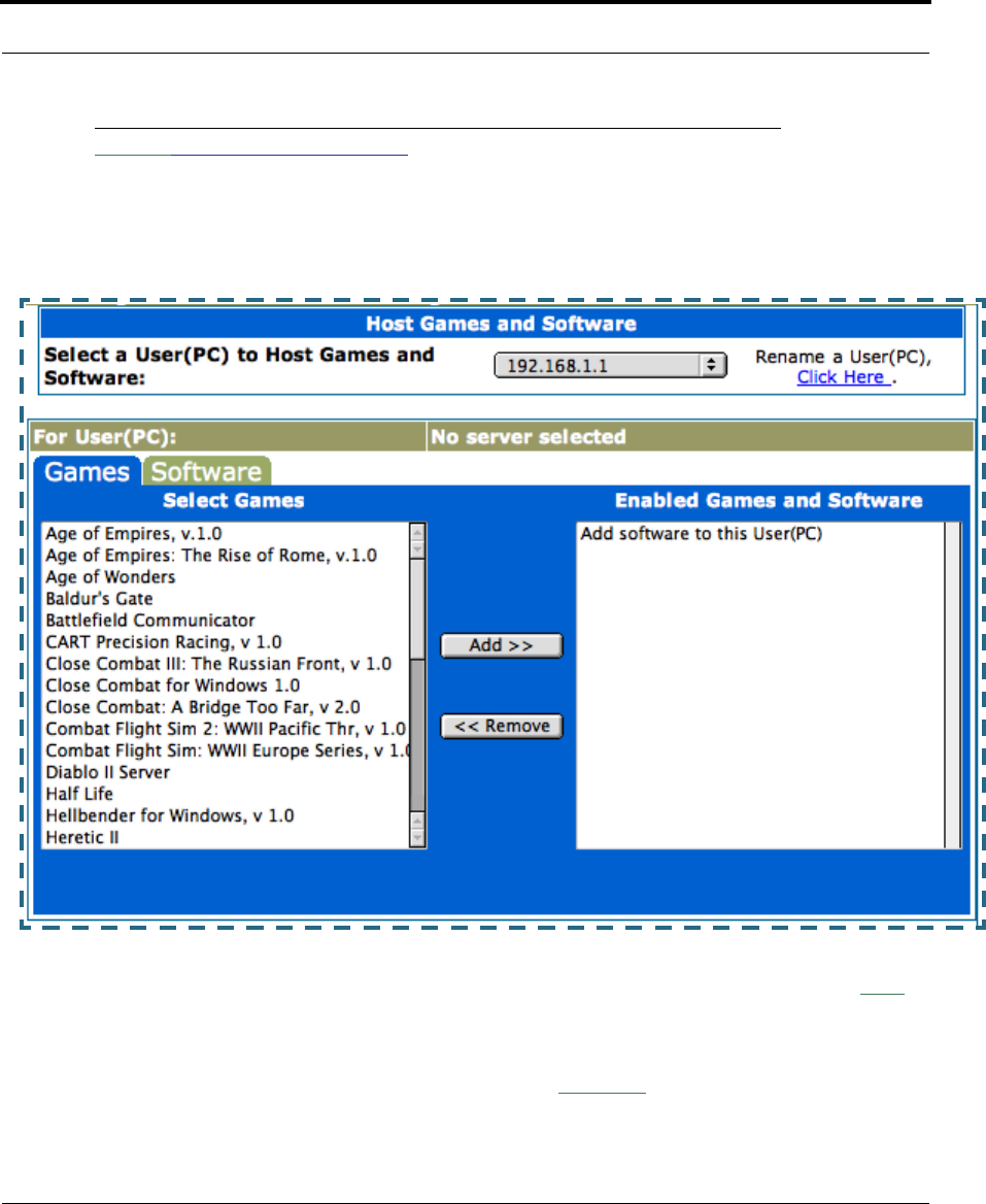
104
Link: Software Hosting
Software Hosting allows you to host internet applications when NAT is
enabled. User(PC) specifies the machine on which the selected software is
hosted. You can host different games and software on different PCs.
To select the games or software that you want to host for a specific PC,
highlight the name(s) in the box on the left side of the screen. Click the
Add
button to select the software that will be hosted.
To remove a game or software from the hosted list, highlight the game or
software you want to remove and click the
Remove
button.

105
Configure
List of Supported Games and Software
Rename a User(PC)
If a PC on your LAN has no assigned host name, you can assign one by
clicking the
Rename a User(PC)
link.
Age of Empires, v.1.0 Age of Empires: The Rise of
Rome, v.1.0 Age of Wonders
Baldur's Gate Battlefield Communicator CART Precision Racing, v
1.0
Close Combat for Windows
1.0 Close Combat: A Bridge Too
Far, v 2.0 Close Combat III: The Rus-
sian Front, v 1.0
Combat Flight Sim: WWII
Europe Series, v 1.0 Combat Flight Sim 2: WWII
Pacific Thr, v 1.0 Diablo II Server
FTP GNUtella H.323 compliant (Netmeet-
ing, CUSeeME)
Half Life Hellbender for Windows, v
1.0 Heretic II
HTTP IPSec Jedi Knight II: Jedi Outcast
Lime Wire Links LS 2000 Mech Warrior 3
Mech Warrior 4: Vengeance Medal of Honor Allied
Assault Microsoft Flight Simulator 98
Microsoft Flight Simulator
2000 Microsoft Golf 1998 Edition,
v 1.0 Microsoft Golf 1999 Edition
Microsoft Golf 2001 Edition Midtown Madness, v 1.0 Monster Truck Madness, v
1.0
Monster Truck Madness 2, v
2.0 pcAnywhere (incoming) POP-3
PPTP Quake II Quake III
SMTP SSH server StarCraft
StarLancer, v 1.0 Telnet Timbuktu
Total Annihilation TFTP Unreal Tournament Server
Urban Assault, v 1.0 Win2000 Terminal Server
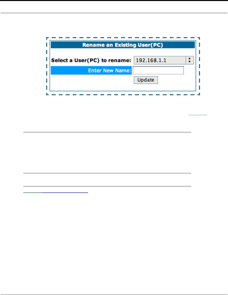
106
To rename a server, select the server from the pull-down menu. Then type a
new name in the text box below the pull-down menu. Click the
Update
but-
ton to save the new name.
☛ NOTE:
The new name given to a server is only known to Software Host-
ing. It is not used as an identifier in other network functions,
such as DNS or DHCP.
Link: Clear Options
To restore the factory configuration of the Gateway, choose Clear Options.
You may want to upload your configuration to a file before performing this
function. You can do this using the upload command via the command-line
interface. See the upload command on page 187.
Clear Options does not clear feature keys or affect the software image or
BootPROM.
You must restart the Gateway for Clear Options to take effect.
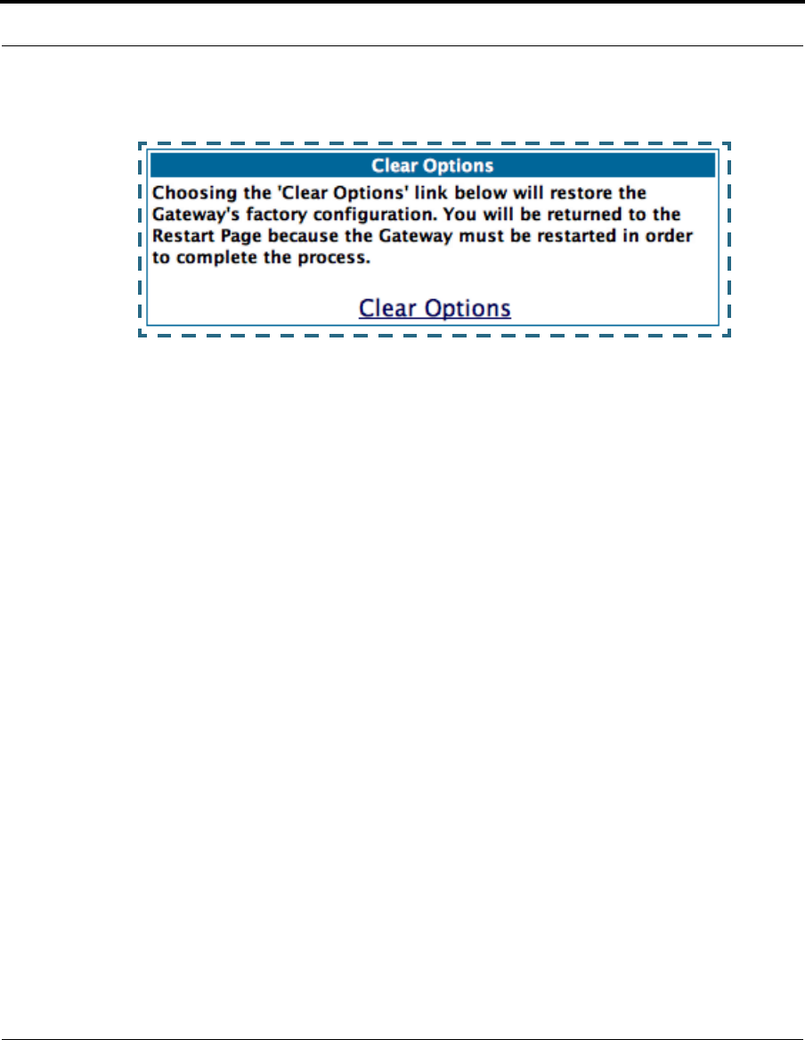
107
Configure
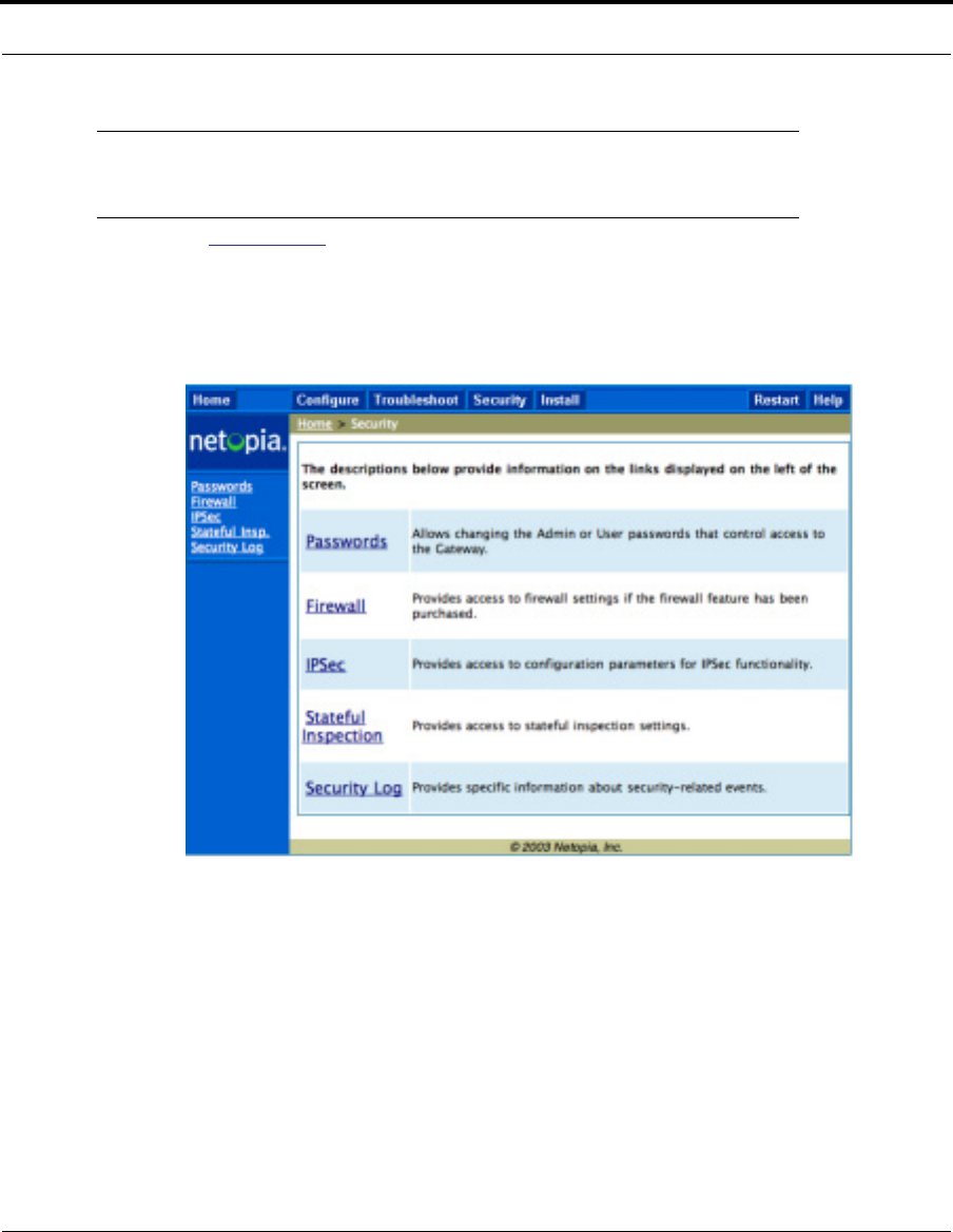
108
Security
Button: Security
The Security features are available by clicking on the Security toolbar but-
ton. Some items of this category do not appear when you log on as User.

109
Security
Link: Passwords
Access to your Gateway may be controlled through two optional user
accounts, Admin and User. When you first power up your Gateway, you cre-
ate a password for the Admin account. The User account does not exist by
default. As the Admin, a password for the User account can be entered or
existing passwords changed.
Create and Change Passwords. You can establish different levels of
access security to protect your Cayman Gateway settings from unauthorized
display or modification.
•Admin level privileges let you display and modify all settings in the Cay-
man Gateway (Read/Write mode). The Admin level password is created
when you first access your Gateway.
•User level privileges let you display (but not change) settings of the Cay-
man Gateway. (Read Only mode)
To prevent anyone from observing the password you enter, characters in the
old and new password fields are not displayed as you type them.
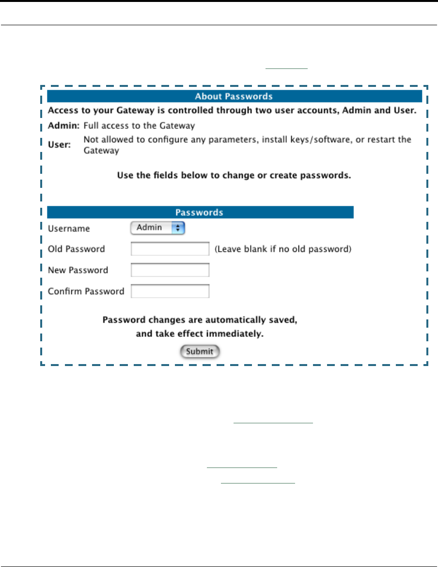
110
To display the Passwords window, click the
Security
toolbar button on the
Home page.
Use the following procedure to change existing passwords or add the User
password for your Cayman Gateway:
1. Select the password type from the
Password Level
pull-down list.
Choose from Admin or User.
2. If you assigned a password to the Cayman Gateway previously, enter
your current password in the
Old Password
field.
3. Enter your new password in the
New Password
field.
Cayman’s rules for a Password are:
•It can have up to eight alphanumeric characters.
•It is case-sensitive.

111
Security
4. Enter your new password again in the
Confirm Password
field.
You confirm the new password to verify that you entered it correctly the
first time.
5. When you are finished, click the
Submit
button to store your modified
configuration in the Cayman unit’s memory.
Password changes are automatically saved, and take effect immediately.
Link: Firewall
Use a Cayman Firewall
BreakWater Basic Firewall. BreakWater delivers an easily selectable set
of pre-configured firewall protection levels. For simple implementation these
settings (comprised of three levels) are readily available through Cayman’s
embedded web server interface.
BreakWater Basic Firewall’s three settings are:
•ClearSailing
ClearSailing, BreakWater's default setting, supports both inbound and
outbound traffic. It is the only basic firewall setting that fully interoper-
ates with all other Cayman software features.
•SilentRunning
Using this level of firewall protection allows transmission of outbound
traffic on pre-configured TCP/UDP ports. It disables any attempt for
inbound traffic to identify the Gateway. This is the Internet equivalent of
having an unlisted number.
•LANdLocked
The third option available turns off all inbound and outbound traffic, iso-
lating the LAN and disabling all WAN traffic.
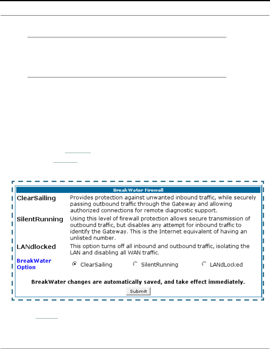
112
☛ NOTE:
BreakWater Basic Firewall operates independent of the NAT func-
tionality on the Gateway.
Configuring for a BreakWater Setting
Use these steps to establish a firewall setting:
1. Ensure that you have enabled the BreakWater basic firewall with the
appropriate feature key.
See See “Use Cayman Software Feature Keys” on page 141. for refer-
ence.
2. Click the
Security
toolbar button.
3. Click
Firewall
.
4. Click on the radio button to select the protection level you want. Click
Submit
.

113
Security
Changing the BreakWater setting does not require a restart to take
effect. This makes it easy to change the setting “on the fly,” as your
needs change.
TIPS for making your BreakWater Basic Firewall Selection
Basic Firewall Background
As a device on the Internet, a Cayman Gateway requires an IP address in
order to send or receive traffic.
The IP traffic sent or received have an associated application port which is
dependent on the nature of the connection request. In the IP protocol stan-
dard the following session types are common applications:
By receiving a response to a scan from a port or series of ports (which is
the expected behavior according to the IP standard), hackers can identify an
existing device and gain a potential opening for access to an internet-con-
nected device.
Application Select this Level Other Considerations
Typical Internet usage
(browsing, e-mail) SilentRunning
Multi-player online
gaming ClearSailing Set Pinholes; once defined, pinholes will be
active whenever ClearSailing is set.
Restore SilentRunning when finished.
Going on vacation LANdLocked Protects your connection while your away.
Finished online use for
the day LANdLocked This protects you instead of disconnecting your
Gateway connection.
Chatting online or using
instant messaging ClearSailing Set Pinholes; once defined, pinholes will be
active whenever ClearSailing is set.
Restore SilentRunning when finished.
•ICMP •HTTP •FTP
•SNMP •telnet •DHCP
114
To protect LAN users and their network from these types of attacks, Break-
Water offers three levels of increasing protection.
The following tables indicate the state of ports associated with session
types, both on the WAN side and the LAN side of the Gateway.
This table shows how inbound traffic is treated. Inbound means the traffic
is coming from the WAN into the WAN side of the Gateway.
This table shows how outbound traffic is treated. Outbound means the traf-
fic is coming from the LAN-side computers into the LAN side of the Gateway.
Gateway: WAN Side
BreakWater Setting >> ClearSailing SilentRunning LANdLocked
Port Session Type --------------Port State-----------------------
20 ftp data Enabled Disabled Disabled
21 ftp control Enabled Disabled Disabled
23 telnet external Enabled Disabled Disabled
23 telnet Cayman server Enabled Disabled Disabled
80 http external Enabled Disabled Disabled
80 http Cayman server Enabled Disabled Disabled
67 DHCP client Enabled Enabled Disabled
68 DHCP server Not Applicable Not Applicable Not Applicable
161 snmp Enabled Disabled Disabled
ping (ICMP) Enabled Disabled Disabled
Gateway: LAN Side
BreakWater Setting >> ClearSailing SilentRunning LANdLocked
Port Session Type --------------Port State-----------------------
20 ftp data Enabled Enabled Disabled
21 ftp control Enabled Enabled Disabled
23 telnet external Enabled Enabled Disabled
23 telnet Cayman server Enabled Enabled Enabled
80 http external Enabled Enabled Disabled
80 http Cayman server Enabled Enabled Enabled

115
Security
☛ NOTE:
The Gateway’s WAN DHCP client port in SilentRunning mode is
enabled. This feature allows end users to continue using DHCP-
served IP addresses from their Service Providers, while having
no identifiable presence on the Internet.
67 DHCP client Not Applicable Not Applicable Not Applicable
68 DHCP server Enabled Enabled Enabled
161 snmp Enabled Enabled Enabled
ping (ICMP) Enabled Enabled WAN - Disabled
LAN -
Local Address
Only
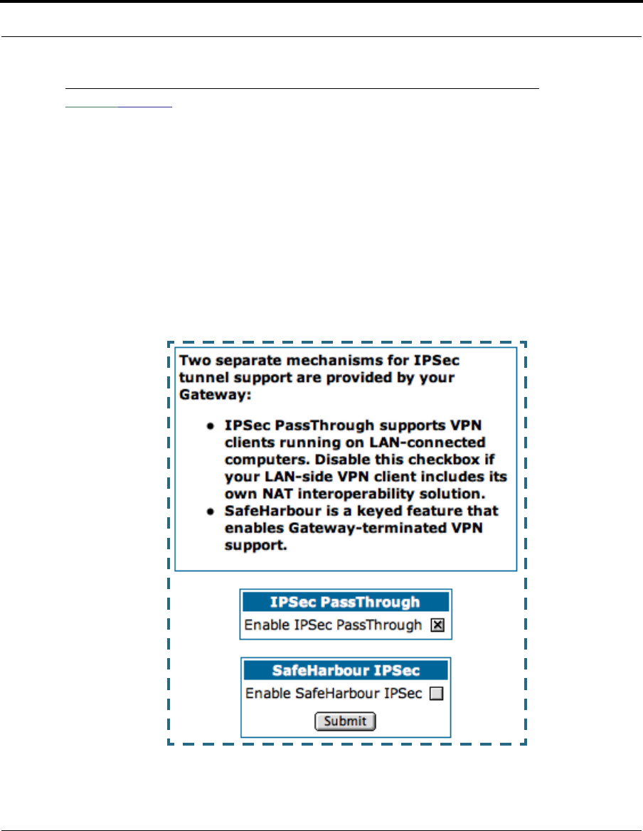
116
Link: IPSec
Your Gateway supports two mechanisms for IPSec tunnels:
1. IPSec PassThrough supports Virtual Private Network (VPN) clients run-
ning on LAN-connected computers. Normally, this feature is enabled. How-
ever, you can disable it if your LAN-side VPN client includes its own NAT
interoperability option.
2. SafeHarbour VPN IPSec is a keyed feature that you must purchase. It
enables Gateway-terminated VPN support.
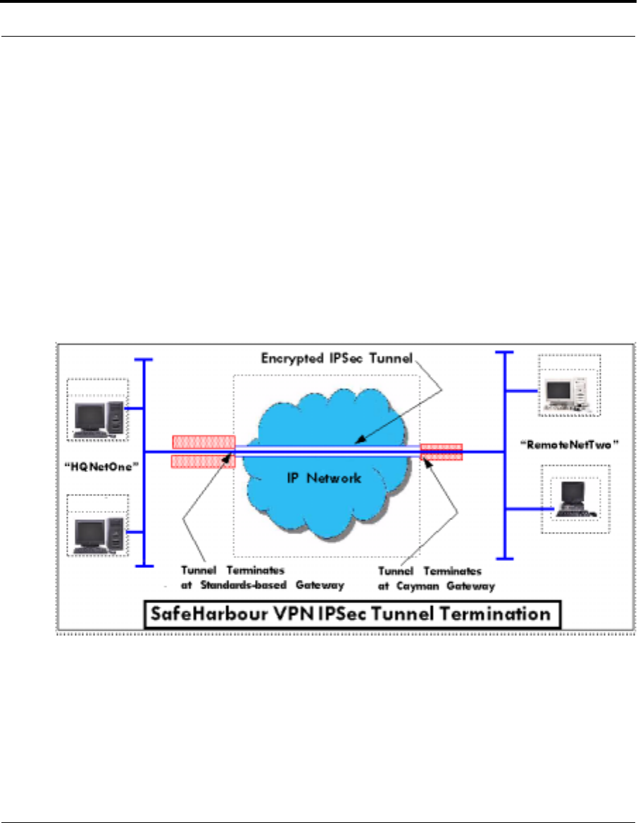
117
Security
How to Configure a SafeHarbour VPN
VPN IPSec Tunnel at the Gateway. SafeHarbour VPN IPSec Tunnel pro-
vides a single, encrypted tunnel to be terminated on the Gateway, making
a secure tunnel available for all LAN- connected Users. This implementation
offers the following:
•Eliminates the need for VPN client software on individual PCs.
•Reduces the complexity of tunnel configuration.
•Simplifies the ongoing maintenance for secure remote access.
A typical SafeHarbour configuration is shown below:
Use these Best Practices in establishing your SafeHarbour tunnel.
1. Ensure that the configuration information is complete and accurate
2. Use the Worksheet provided on page 120.

118
Parameter Description and Setup. The following table describes SafeHar-
bour’s parameters that are used for an IPSec VPN tunnel configuration:
Auth Protocol Authentication Protocol for IP packet header. The three parameter
values are None, Encapsulating Security Payload (ESP) and Authen-
tication Header (AH)
DH Group Diffie-Hellman is a public key algorithm used between two systems to
determine and deliver secret keys used for encryption. Groups 1, 2
and 5 are supported.
Enable This toggle button is used to enable/disable the configured tunnel.
Encrypt Protocol Encryption protocol for the tunnel session.
Parameter values supported include NONE or ESP.
Hard MBytes Setting the Hard MBytes parameter forces the renegotiation of the
IPSec Security Associations (SAs) at the configured Hard MByte
value.
The value can be configured between 1 and 1,000,000 MB and refers
to data traffic passed.
Hard Seconds Setting the Hard Seconds parameter forces the renegotiation of the
IPSec Security Associations (SAs) at the configured Hard Seconds
value. The value can be configured between 60 and 1,000,000 sec-
onds
Key Management The Key Management algorithm manages the exchange of security
keys in the IPSec protocol architecture. SafeHarbour supports the
standard Internet Key Exchange (IKE)
Peer External IP
Address The Peer External IP Address is the public, or routable IP address of
the remote gateway or VPN server you are establishing the tunnel
with.
Peer Internal IP
Network The Peer Internal IP Network is the private, or Local Area Network
(LAN) address of the remote gateway or VPN Server you are commu-
nicating with.
Peer Internal IP
Netmask The Peer Internal IP Netmask is the subnet mask of the Peer Internal
IP Network.
PFS Enable Perfect Forward Secrecy (PFS) is used during SA renegotiation.
When PFS is selected, a Diffie-Hellman key exchange is required. If
enabled, the PFS DH group follows the IKE phase 1 DH group.
Pre-Shared Key The Pre-Shared Key is a parameter used for authenticating each
side. The value can be an ASCII or Hex and a maximum of 64 charac-
ters. ASCII is case-sensitive.
Pre-Shared Key
Type The Pre-Shared Key Type classifies the Pre-Shared Key. SafeHarbour
supports ASCII or HEX types

119
Security
Name The Name parameter refers to the name of the configured tunnel.
This is mainly used as an identifier for the administrator. The Name
parameter is an ASCII value and is limited to 31characters. The tun-
nel name is the only IPSec parameter that does not need to match
the peer gateway.
Negotiation
Method This parameter refers to the method used during the Phase I key
exchange, or IKE process. SafeHarbour supports Main or Aggressive
Mode. Main mode requires 3 two-way message exchanges while
Aggressive mode only requires 3 total message exchanges.
SA Encrypt Type SA Encryption Type refers to the symmetric encryption type. This
encryption algorithm will be used to encrypt each data packet. SA
Encryption Type values supported include DES and 3DES.
SA Hash Type SA Hash Type refers to the Authentication Hash algorithm used dur-
ing SA negotiation. Values supported include MD5 and SHA1. N/A
will display if NONE is chosen for Auth Protocol.
Soft MBytes Setting the Soft MBytes parameter forces the renegotiation of the
IPSec Security Associations (SAs) at the configured Soft MByte
value. The value can be configured between 1 and 1,000,000 MB and
refers to data traffic passed. If this value is not achieved, the Hard
MBytes parameter is enforced.
Soft Seconds Setting the Soft Seconds parameter forces the renegotiation of the
IPSec Security Associations (SAs) at the configured Soft Seconds
value. The value can be configured between 60 and 1,000,000 sec-
onds.

120
IPSec Tunnel Parameter Setup Worksheet.
SafeHarbour Tunnel Setup. Use the following tasks to configure an IPSec
VPN tunnel on your Cayman Gateway.
Parameter Cayman Peer Gateway
Name
Peer External IP Address
Peer Internal IP Network
Peer Internal IP Netmask
Enable
Encrypt Protocol None
ESP
Auth Protocol None
ESP
AH
Key Management IKE
Pre-Shared Key Type HEX
ASCII
Pre-Shared Key
Negotiation Method Main
Aggressive
DH Group 1
2
5
SA Encrypt Type DES
3DES
SA Hash Type N/A
MD5
SHA1
PFS Enable Off
On
Soft MBytes 1 - 1000000
Soft Seconds 60 - 1000000
Hard MBytes 1 - 1000000
Hard Seconds 60 - 1000000

121
Security
Task 1: Ensure that you have SafeHarbour VPN enabled.
SafeHarbour is a keyed feature. See page 141 for information concerning
installing Cayman Software Feature Keys.
Task2: Complete Parameter Setup Worksheet
IPSec tunnel configuration requires precise parameter set between VPN
devices. The Setup Worksheet facilitates setup and assures that the asso-
ciated variables are identical.
Task 3: Enable IPSec
IPSec must be enabled on your Gateway to allow further VPN configuration.
Perform the following steps to enable IPSec:
1. Browse to Gateway.
2. Click the
Security
toolbar button.
3. Click the
IPSec
link.
4. Check the
Enable SafeHarbour IPSec
checkbox.
Checking this box will automatically display the SafeHarbour IPSec
Tunnel Entry parameters.
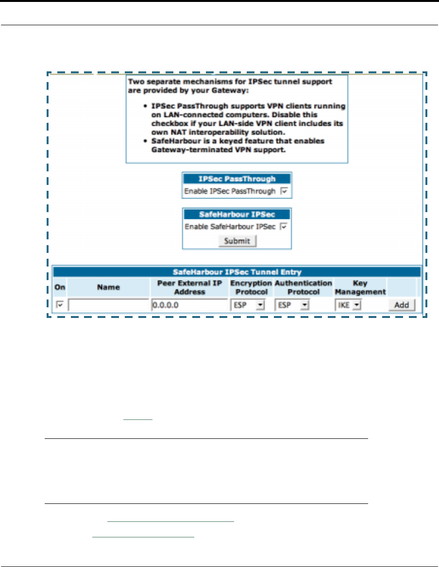
122
Task 4: Make the IPSec Tunnel Entries
Enter the initial group of tunnel parameters. Refer to your Setup Work-
sheet and the Glossary of VPN Terms as required. Perform the following
steps:
1. Enter tunnel
Name
.
☛
This is the only parameter that does not have to be identical to
the peer/remote VPN device
2. Enter the
Peer External IP Address
.
3. Select
Encryption Protocol
from the pull-down menu.
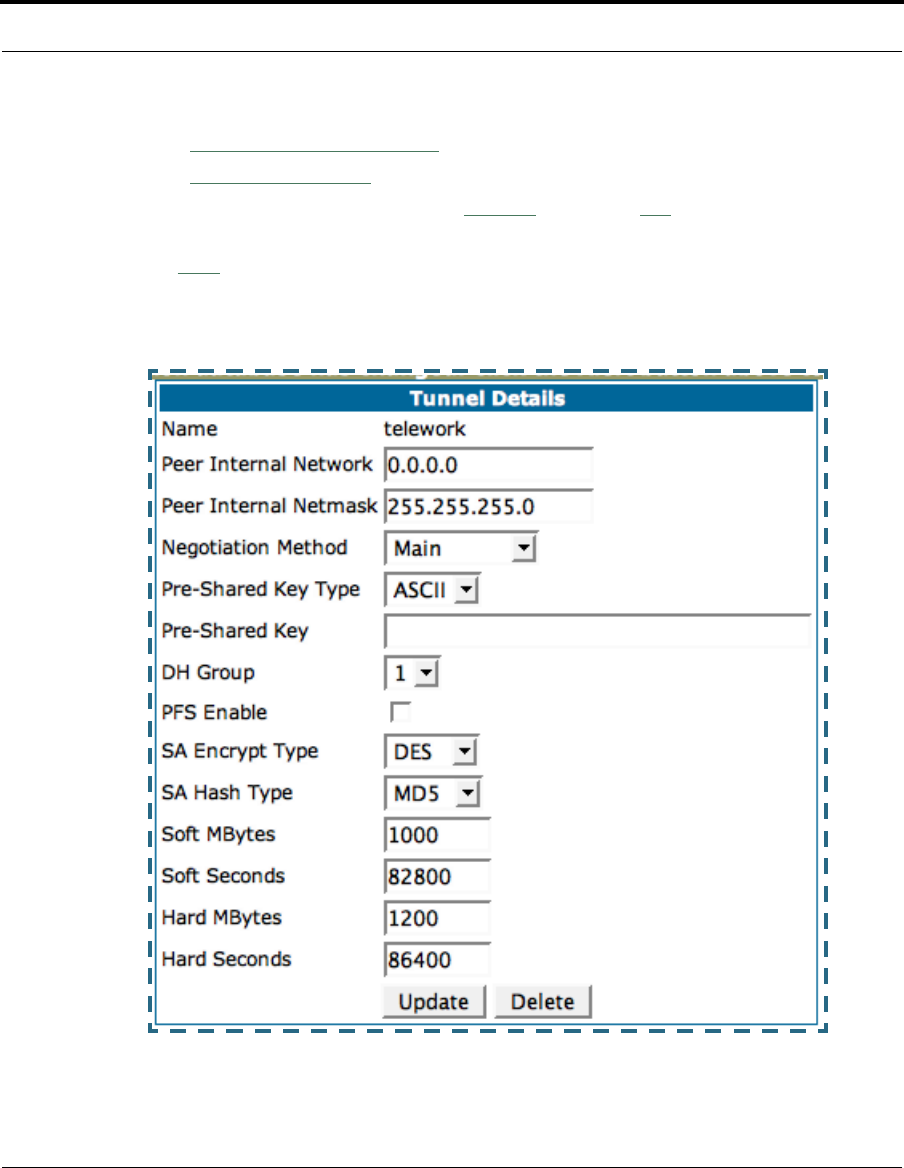
123
Security
4. Select
Authentication Protocol
from the pull-down menu.
5. Select
Key Management
from the pull-down menu.
6. Ensure that the toggle checkbox
Enable
, which is
On
by default, remains
On.
7. Click
Add
.
The Tunnel Details page appears.

124
Task 5: Make the Tunnel Details entries
Use the following steps:
1. Enter or select the required settings.
2. Click
Update
. The
Alert
button appears.
3. Click the
Alert
button.
4. Click
Save and Restart
.
Your SafeHarbour IPSec VPN tunnel is fully configured.
Tunnel sessions can only be initiated from the LAN client side.

125
Security
Link: Stateful Inspection
All computer operating systems are vulnerable to attack from outside
sources, typically at the operating system or Internet Protocol (IP) layers.
Stateful Inspection firewalls intercept and analyze incoming data packets to
determine whether they should be admitted to your private LAN, based on
multiple criteria, or blocked. Stateful inspection improves security by track-
ing data packets over a period of time, examining incoming and outgoing
packets. Outgoing packets that request specific types of incoming packets
are tracked; only those incoming packets constituting a proper response
are allowed through the firewall.
Stateful inspection is a security feature that prevents unsolicited inbound
access when NAT is disabled. You can configure UDP and TCP “no-activity”
periods that will also apply to NAT time-outs if stateful inspection is enabled
on the interface. Stateful Inspection parameters are active on a WAN inter-
face only if enabled on your Gateway. Stateful inspection can be enabled on
a profile whether NAT is enabled or not.
Stateful Inspection Firewall installation procedure
☛ NOTE:
Installing Stateful Inspection Firewall is mandatory to comply with
Required Services Security Policy - Residential Category module -
Version 4.0 (specified by ICSA Labs)
For more information please go to the following URL:
http://www.icsalabs.com/html/communities/firewalls/certification/
criteria/Residential.pdf
.
1. Access the router through the web interface from the private LAN.
DHCP server is enabled on the LAN by default.
2. There will be a prompt to set up the administrative password. The default
Username is
admin
and this cannot be changed.
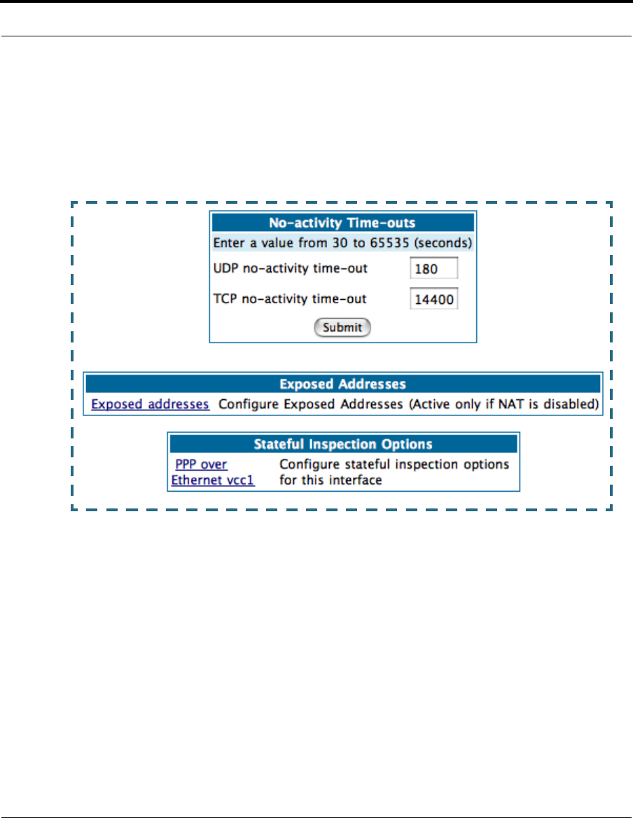
126
3. The Gateway’s Stateful Inspection feature must be enabled in order to
prevent TCP, UDP and ICMP packets destined for the router or the private
hosts.
This can be done by navigating to Expert Mode -> Security -> Stateful
Inspection.
•UDP no-activity time-out: The time in seconds after which a UDP ses-
sion will be terminated, if there is no traffic on the session.
•TCP no-activity time-out: The time in seconds after which an TCP ses-
sion will be terminated, if there is no traffic on the session.
•Exposed Addresses: The hosts specified in Exposed addresses will be
allowed to receive inbound traffic even if there is no corresponding out-
bound traffic. This is active only if NAT is disabled on an WAN interface.
•Stateful Inspection Options: Enable and configure stateful inspection
on a WAN interface.
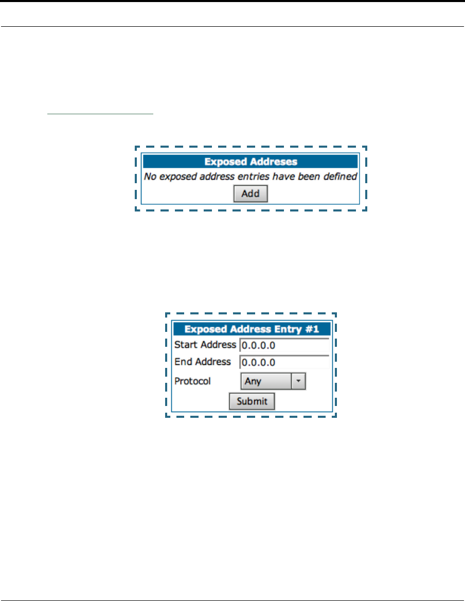
127
Security
Exposed Addresses
You can specify the IP addresses you want to expose by clicking the
Exposed addresses
link.
Add, Edit, or delete exposed addresses options are active only if NAT is dis-
abled on a WAN interface. The hosts specified in exposed addresses will be
allowed to receive inbound traffic even if there is no corresponding out-
bound traffic.
•Start Address: Start IP Address of the exposed host range.
•End Address: End IP Address of the exposed host range
•Protocol: Select the Protocol of the traffic to be allowed to the host
range from the pull-down menu. Options are Any, TCP, UDP, or TCP/UDP.
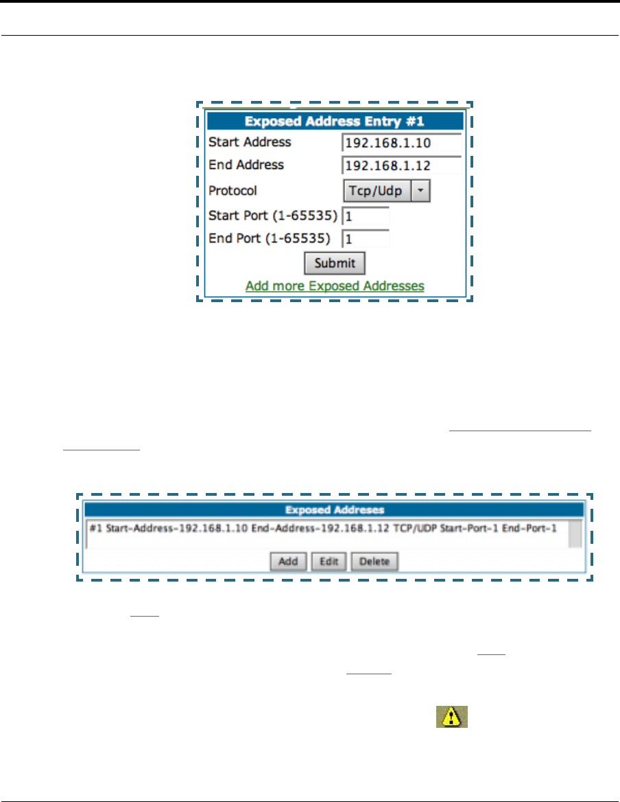
128
•Start Port: Start port of the range to be allowed to the host range. The
acceptable range is from 1 - 65535
•End Port: Protocol of the traffic to be allowed to the host range. The
acceptable range is from 1 - 65535
You can add more exposed addresses by clicking the
Add more Exposed
Addresses
link. A list of previously configured exposed addresses appears.
Click the
Add
button to add a new range of exposed addresses.
You can edit a previously configured range by clicking the
Edit
button, or
delete the entry entirely by clicking the
Delete
button.
All configuration changes will trigger the Alert Icon. Click on the Alert
icon.
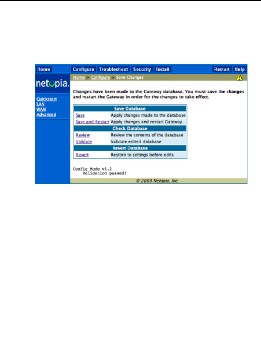
129
Security
This allows you to validate the configuration and reboot the Gateway.
Click the
Save and Restart
link. You will be asked to confirm your choice,
and the Gateway will reboot with the new configuration.
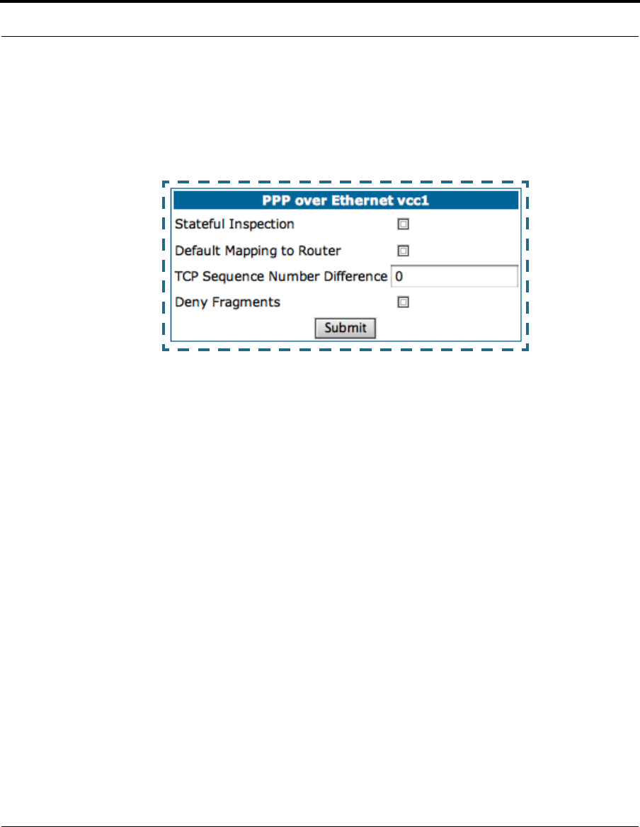
130
Stateful Inspection Options
Stateful Inspection Parameters are active on a WAN interface only if you
enable them on your Gateway.
•Stateful Inspection: To enable stateful inspection on this WAN inter-
face, check the checkbox.
•Default Mapping to Router: This is disabled by default. This option will
allow the router to respond to traffic received on this interface, for exam-
ple, ICMP Echo requests.
•TCP Sequence Number Difference: Enter a value in this field. This
value represents the maximum sequence number difference allowed
between subsequent TCP packets. If this number is exceeded, the
packet is dropped. The acceptable range is 0 – 65535. A value of 0
(zero) disables this check.
•Deny Fragments: To enable this option, which causes the router to dis-
card fragmented packets on this interface, check the checkbox.

131
Security
Open Ports in Default Stateful Inspection Installation
Log Event Dispositions
☛ NOTE:
Syslog needs to be enabled to comply with logging requirements
mentioned in The Modular Firewall Certification Criteria - Baseline
Module - version 4.0 (specified by ICSA Labs).
See “Syslog Parameters” on page 101.
For more information, please go to the following URL:
http://www.icsalabs.com/html/communities/firewalls/certification/
criteria/Baseline.pdf
Port Protocol Description Private
Interface Public
Interface
23 TCP telnet Yes No
53 UDP DNS Yes No
67 UDP Bootps Yes No
68 UDP Bootpc Yes No
80 TCP HTTP Yes No
137 UDP Netbios-ns Yes No
138 UDP Netbios-dgm Yes No
161 UDP SNMP Yes No
500 UDP ISAKMP Yes No
520 UDP Router Yes No

132
Link: Security Log
Security Monitoring is a keyed feature. See page 141 for information con-
cerning installing Cayman Software Feature Keys.
Security Monitoring detects security-related events, including common
types of malicious attacks, and writes them to the security log file.
Using the Security Monitoring Log
You can view the Security Log at any time. Use the following steps:
1. Click the
Security toolbar button.
2. Click the
Security Log
link.
3. Click the
Show
link from the Security Log tool bar.
4. An example of the Security Log is shown on the next page.
5. When a new security event is detected, you will see the
Alert
button.
The Security Alert remains until you view the information. Clicking the
Alert button will take you directly to a page showing the log.
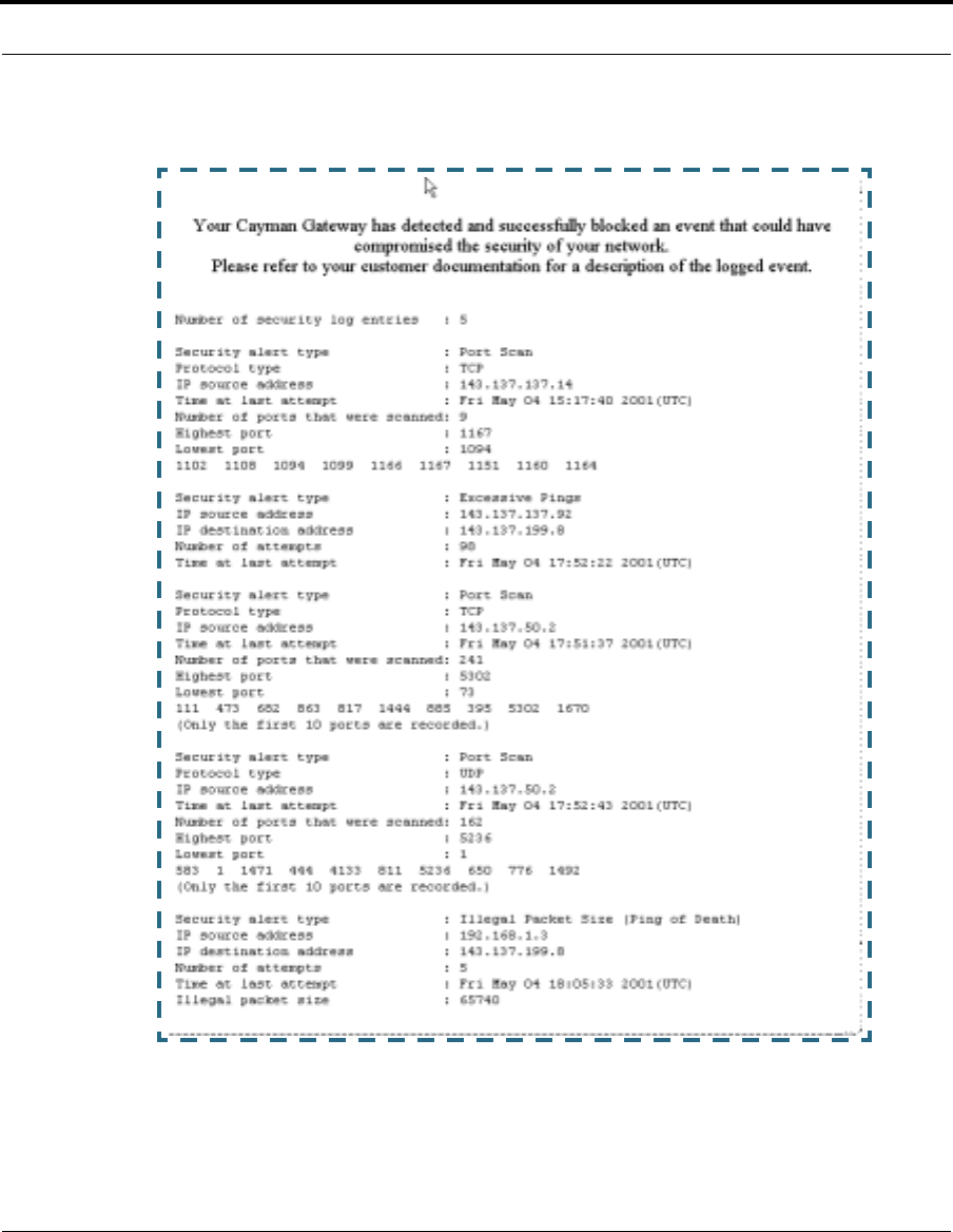
133
Security
The capacity of the security log is 100 security alert messages. When the
log reaches capacity, subsequent messages are not captured, but they are
noted in the log entry count.
134
To reset this log, select
Reset
from the Security Monitor tool bar.
The following message is displayed.
When the Security Log contains no entries, this is the response:
Timestamp Background
During bootup, to provide better log information and to support improved
troubleshooting, a Cayman Gateway acquires the National Institute of Stan-
dards and Technology (NIST) Universal Coordinated Time (UTC) reference
signal, and then adjusts it for your local time zone.
Once per hour, the Gateway attempts to re-acquire the NIST reference, for
re-synchronization or initial acquisition of the UTC information. Once
acquired, all subsequent log entries display this date and time information.
UTC provides the equivalent of Greenwich Mean Time (GMT) information.
If the WAN connection is not enabled, the internal clocking function of the
Gateway provides log timestamps based on “uptime” of the unit.
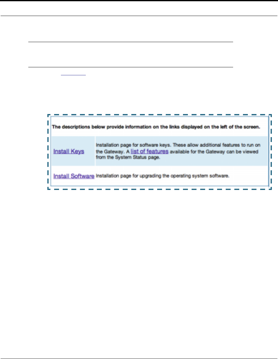
135
Install
Install
Button: Install
From the Install toolbar button you can Install new Operating System Soft-
ware as updates become available.
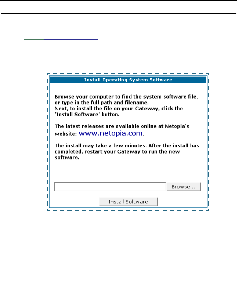
136
Link: Install Software
This page allows you to install an updated release of the Cayman Operating
System (CaymanOS).
Updating Your Gateway’s CaymanOS Version. You install a new operat-
ing system image in your unit from the Install Operating System Software
page. For this process, the computer you are using to connect to the Cay-
man Gateway must be on the same local area network as the Cayman Gate-
way.
Required Tasks
•“Task 1: Required Files” on page 137
•“Task 2: CaymanOS Image File” on page 137

137
Install
Task 1: Required Files
Upgrading the CaymanOS requires a Cayman Operating System image file.
Background
Software upgrade image files are posted periodically on the Netopia web-
site. You can download the latest operating system software for your Gate-
way from the following URL:
http://www.netopia.com/en-us/equipment/purchase/fmw_update.html
When you download your operating system upgrade from the Netopia web-
site, be sure to download the latest release notes or User Guide PDF files.
These are posted on the same Web page as the software.
Confirm CaymanOS Image Files
The CaymanOS Image file is specific to the model and the product identifica-
tion (PID) number.
1. Confirm that you have received the appropriate CaymanOS Image file.
2. Save the CaymanOS image file to a convenient location on your PC.
Task 2: CaymanOS Image File
Install the CaymanOS Image
To install the CaymanOS software in your Cayman Gateway from the
Home
Page
use the following steps:
1. Open a web connection to your Cayman Gateway from the computer on
your LAN.
2. Click the
Install Software
button on the Cayman Gateway
Home
page.
The Install New Cayman Software window opens.
3. Enter the filename into the text box by using one of these techniques:
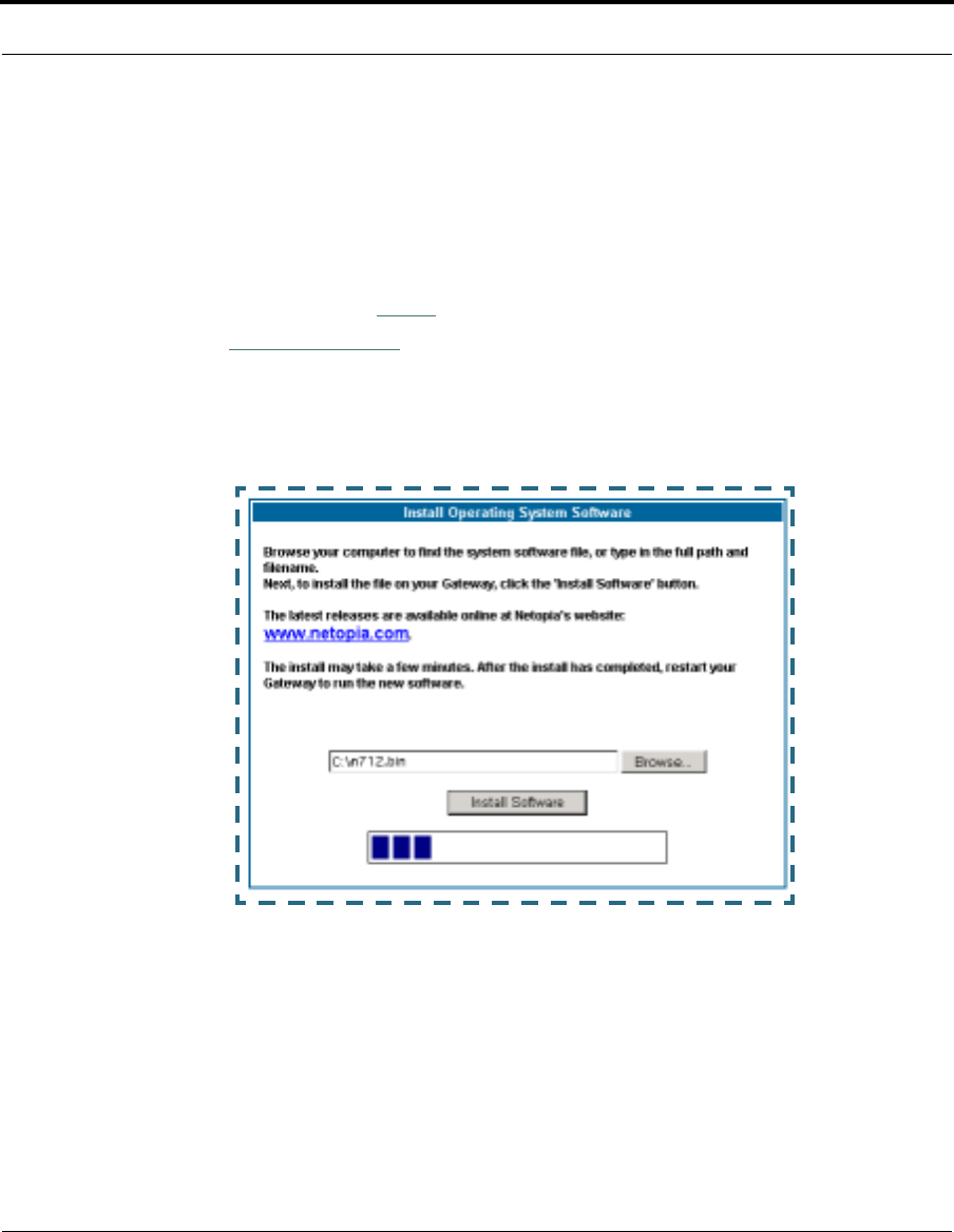
138
The CaymanOS file name begins with a shortened form of the version
number and ends with the suffix “.bin” (for “binary”). Example: n720.bin
a. Click the Browse button, select the file you want, and click Open.
-or-
b. Enter the name and path of the software image you want to install in
the text field and click
Open
.
4. Click the
Install Software
button.
The Cayman Gateway copies the image file from your computer and
installs it into its memory storage. You see a progress bar appear on
your screen as the image is copied and installed.
When the image has been installed, a success message displays.
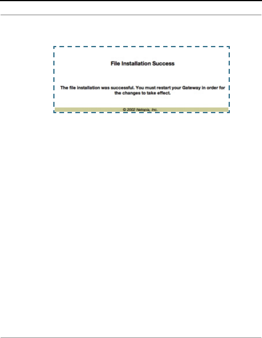
139
Install
5. When the success message appears, click the Restart button and confirm
the Restart when you are prompted.
Your Cayman Gateway restarts with its new image.
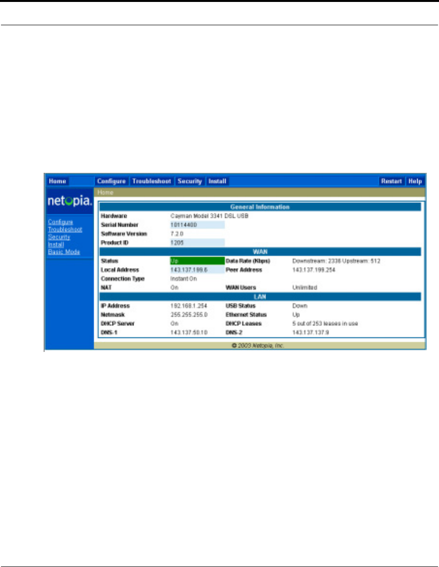
140
Verify the CaymanOS Release
To verify that the CaymanOS image has loaded successfully, use the follow-
ing steps:
1. Open a web connection to your Cayman Gateway from the computer on
your LAN and return to the Home page.
2. Verify your CaymanOS Software Release, as shown on the Home Page.
This completes the upgrade process.

141
Install
Link: Install Keys
You can obtain advanced product functionality by employing a software Fea-
ture Key. Software feature keys are specific to a Gateway's serial number.
Once the feature key is installed and the Gateway is restarted, the new fea-
ture's functionality becomes enabled.
Use Cayman Software Feature Keys
Cayman Gateway users obtain advanced product functionality by installing a
software feature key. This concept utilizes a specially constructed and dis-
tributed keycode (referred to as a feature key) to enable additional capabil-
ity within the unit.
Software feature key properties are specific to a unit’s serial number; they
will not be accepted on a platform with another serial number.
Once installed, and the Gateway restarted, the new feature’s functionality
becomes available. This allows full access to configuration, operation,
maintenance and administration of the new enhancement.
Obtaining Software Feature Keys
Contact Netopia or your Service Provider to acquire a Software Feature Key.
Procedure - Install a New Feature Key File
With the appropriate feature keycode, use the steps listed below to enable
a new function.
1. From the Home page, click the
Install
toolbar button.
2. Click
Install Keys
The Install Key File page appears.
3. Enter the feature keycode in the input Text Box.
Type the full keycode in the Text Box.
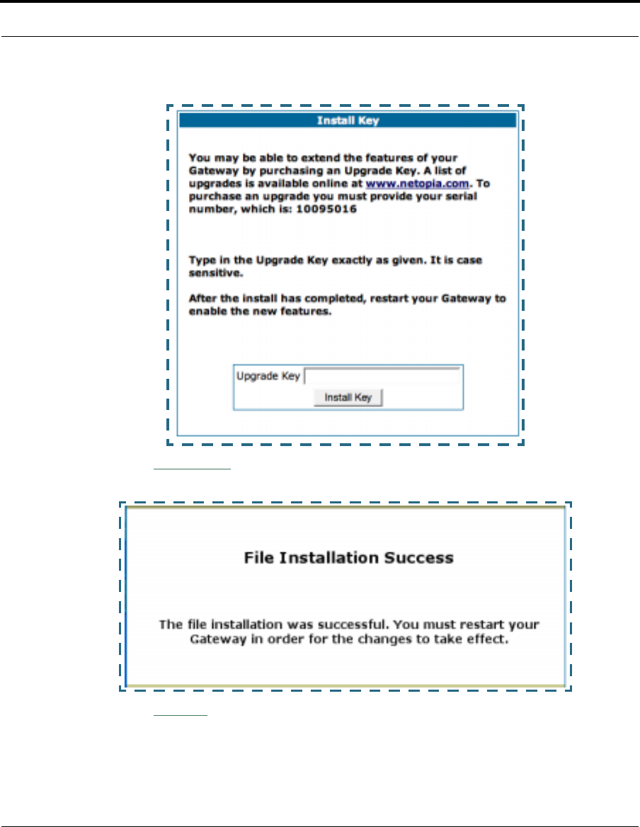
142
4. Click the
Install Key
button.
5. Click the
Restart
toolbar button.
The Confirmation screen appears.
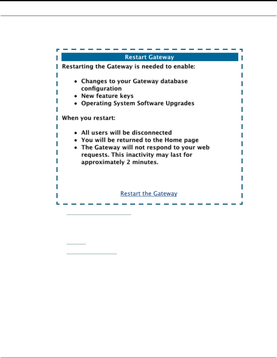
143
Install
6. Click the
Restart the Gateway
link to confirm.
To check your installed features:
7. Click the
Install
toolbar button.
8. Click the
List of Features
link.
The System Status page appears with the information from the features
link displayed below. You can check that the feature you just installed is
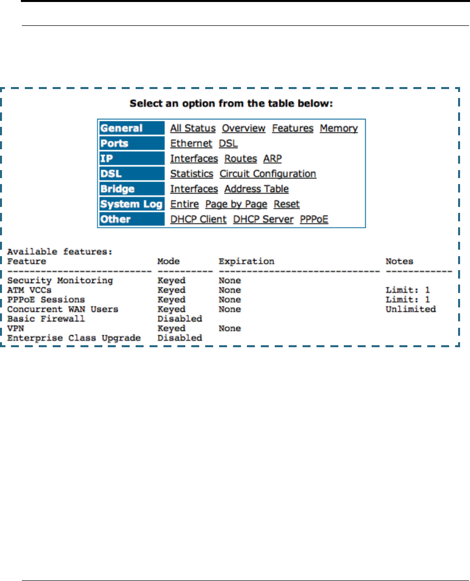
144
enabled.

147
CHAPTER 4 Basic
Troubleshooting
This section gives some simple suggestions for troubleshooting
problems with your Gateway’s initial configuration.
Before troubleshooting, make sure you have
•read the Quickstart Guide;
•plugged in all the necessary cables; and
•set your PC’s TCP/IP controls to obtain an IP address auto-
matically.
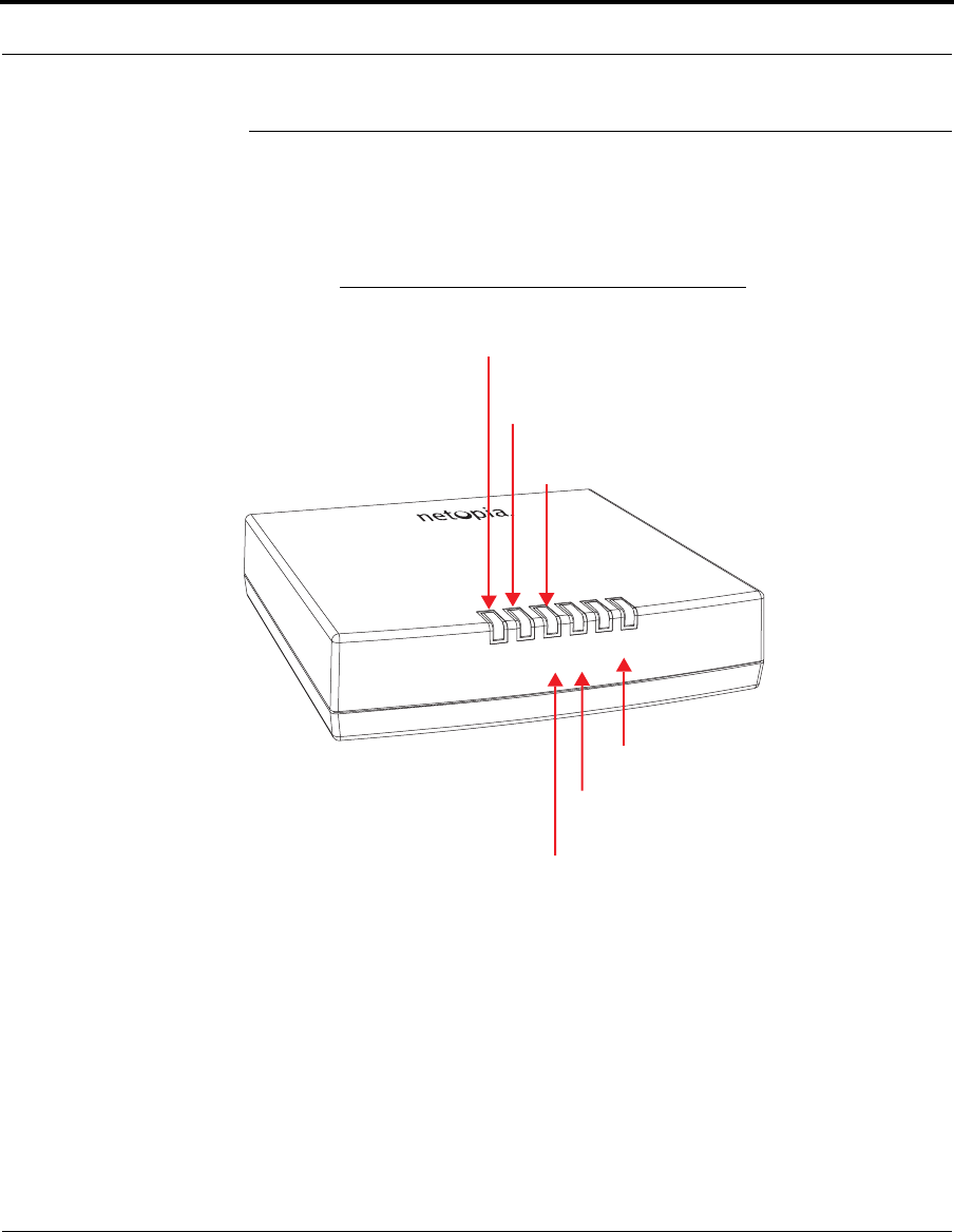
148
Status Indicator Lights
The first step in troubleshooting is to check the status indicator
lights (LEDs) in the order outlined below.
Cayman Gateway 3340 status indicator lights
Ethernet Link
Ethernet Traffic
DSL Traffic
DSL Sync
PPPoE Active
Power
Power:
PPPoE Active:
DSL Traffic:
Solid green when the power is on
Solid green when PPPoE is negotiated;
Blinks green when traffic is sent/received
DSL Sync:
Blinking green with no line attached or training,
Ethernet Traffic:
Flashes green when there is
activity on the LAN
Ethernet Link:
Solid green when connected
otherwise, not lit
solid green when trained with the DSL line.
over the WAN
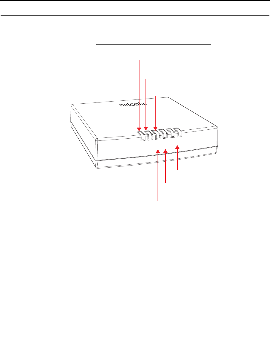
149
Status Indicator Lights
Cayman Gateway 3341 status indicator lights
Ethernet Link
Ethernet Traffic
DSL Traffic
DSL Sync
USB Active
Power
Power:
USB Active:
DSL Traffic:
Solid green when the power is on
Solid green when USB is connected
Blinks green when traffic is sent/received
DSL Sync:
Blinking green with no line attached or training,
Ethernet Traffic:
Flashes green when there is
activity on the LAN
Ethernet Link:
Solid green when connected
otherwise, not lit
solid green when trained with the DSL line.
over the WAN
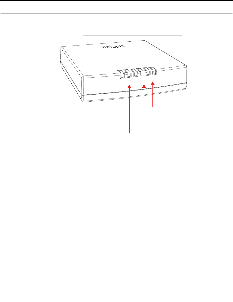
150
Cayman Gateway 3346 status indicator lights
LAN 1
LAN 2
LAN 3
LAN 4
DSL SYNC
Power
Power:
DSL Sync:
Solid green when trained with the DSL line
Blinks green when traffic is sent or received
LAN 1, 2, 3, 4:
over the Ethernet
Solid green when the power is on
Blinks green with no line attached or training,
Solid green when Ethernet link is established
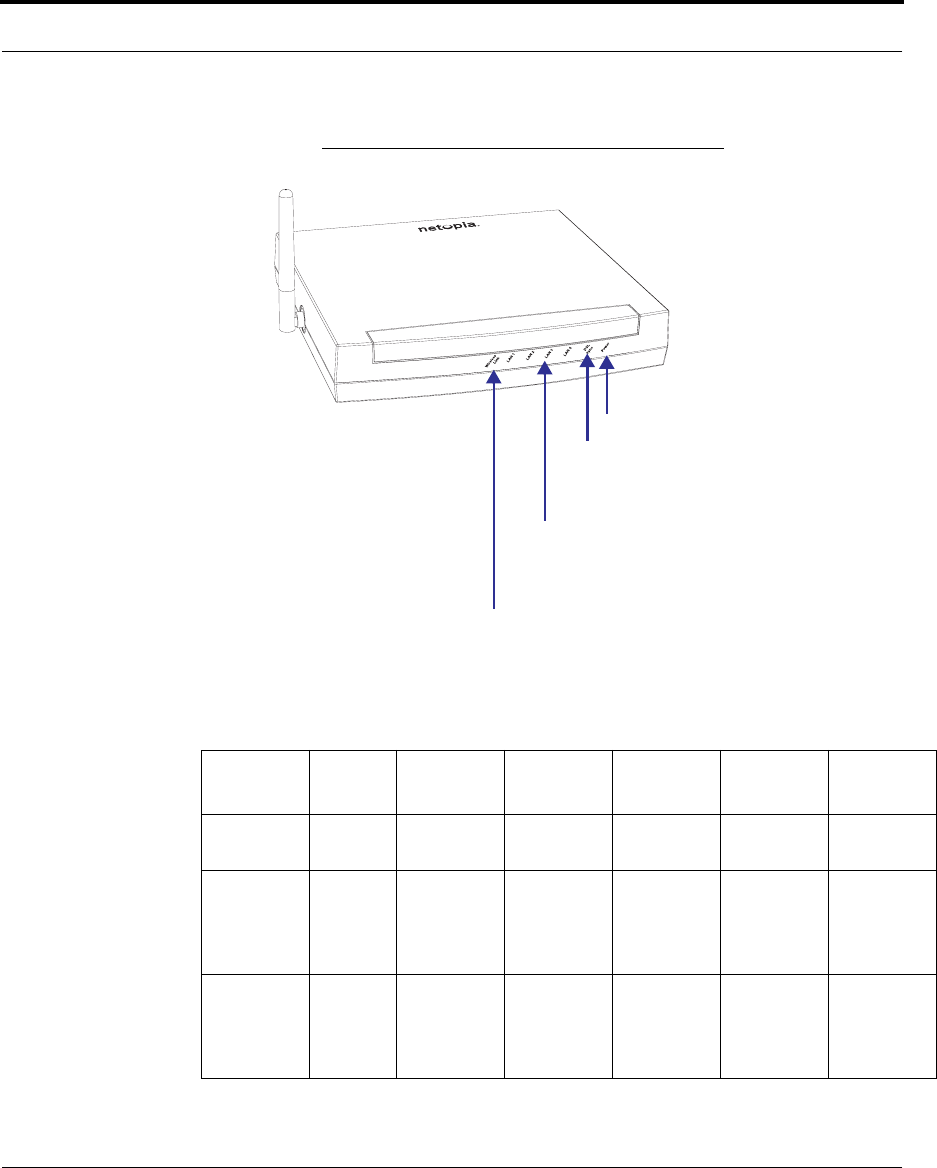
151
Status Indicator Lights
Cayman Gateway 3347W status indicator lights
LED Function Summary Matrix
Power USB
Active DSL
Sync DSL
Traffic Ethernet
Traffic Ethernet
Link
Unlit No
power No signal No signal No signal No signal No signal
Solid
Green Power
on USB port
con-
nected to
PC
DSL line
synched
with the
DSLAM
N/A N/A Synched
with
Ethernet
card
Flashing
Green N/A Activity
on the
USB
cable
Attempt-
ing to
train with
DSLAM
Activity
on the
DSL
cable
Activity
on the
Ethernet
cable
N/A
Power - Green when power is applied
Flashes green when training
Solid green when connected
Solid green when trained
to each port on the LAN.
LAN 1, 2, 3, 4 -
DSL SYNC -
Flash green when there is
activity on each port.
3347W Front View
Flashes green for DSL traffic
Wireless Link - Flashes green when there is
activity on the wireless LAN.

152
If a status indicator light does not look correct, look for these
possible problems:
LED State Possible problems
Power Unlit
1. Make sure the power switch is in the ON
position.
2. Make sure the power adapter is plugged
into the 3300-series DSL Gateway properly.
3. Try a known good wall outlet.
4. Replace the power supply and/or unit.
DSL
Sync Unlit
1. Make sure the you are using the correct
cable. The DSL cable is the thinner stan-
dard telephone cable.
2. Make sure the DSL cable is plugged into
the correct wall jack.
3. Make sure the DSL cable is plugged into
the DSL port on the 3300-series DSL Gate-
way.
4. Make sure the DSL line has been activated
at the central office DSLAM.
5. Make sure the 3300-series DSL Gateway is
not plugged into a micro filter.

153
Status Indicator Lights
EN Link Unlit
Note: EN Link light is inactive if only using USB.
1. Make sure the you are using the Ethernet
cable, not the DSL cable. The Ethernet
cable is thicker than the standard telephone
cable.
2. Make sure the Ethernet cable is securely
plugged into the Ethernet jack on the PC.
3. If plugging a 3300-series DSL Gateway into
a hub the you may need to plug into an
uplink port on the hub, or use an Ethernet
cross over cable.
4. Make sure the Ethernet cable is securely
plugged into the Ethernet port on the 3300-
series DSL Gateway.
5. Try another Ethernet cable if you have one
available.
EN
Traffic Unlit
1. Make sure you have Ethernet drivers
installed on the PC.
2. Make sure the PC’s TCP/IP Properties for
the Ethernet Network Control Panel is set to
obtain an IP address via DHCP.
3. Make sure the PC has obtained an address
in the 192.168.1.x range. (You may have
changed the subnet addressing.)
4. Make sure the PC is configured to access
the Internet over a LAN.
5. Disable any installed network devices
(Ethernet, HomePNA, wireless) that are not
being used to connect to the 3300-series
DSL Gateway.

154
USB
Active Unlit
Note: USB Active light is inactive if only using
Ethernet.
1. Make sure you have USB drivers installed
on the PC.
2. Make sure the PC’s TCP/IP Properties for
the USB Network Control Panel is set to
obtain an IP address via DHCP.
3. Make sure the PC has obtained an address
in the 192.168.1.x range. (You may have
changed the subnet addressing.)
4. Make sure the PC is configured to access
the Internet over a LAN.
5. Disable any installed network devices
(Ethernet, HomePNA, wireless) that are not
being used to connect to the 3300-series
DSL Gateway.
DSL
Traffic Unlit Launch a browser and try to browse the Internet. If
the DSL Active light still does not flash, then pro-
ceed to Advanced Troubleshooting below.
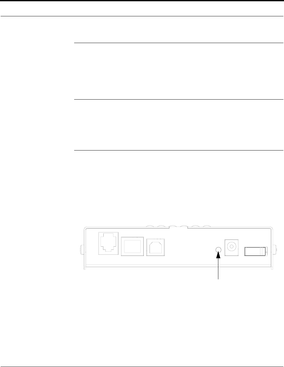
155
Factory Reset Switch
Factory Reset Switch
Lose your password? This section shows how to reset the Cay-
man Gateway so that you can access the configuration screens
once again.
☛ NOTE:
Keep in mind that all of your settings will need to be
reconfigured.
If you don't have a password, the only way to access the Cay-
man Gateway is the following:
1. Referring to the diagram below, find the round Reset Switch
opening.
2. Carefully insert the point of a pen or an unwound paperclip
into the opening.
3. Press this switch very briefly. Don’t hold it more than a sec-
ond.
4. This will reset the unit to factory defaults and you will now be
able to reprogram the Cayman Gateway.
1
Power
4
USB
3
Ethernet
2
DSL On / Off
Factory Reset Switch: Push to clear all settings

156

157
CHAPTER 5 Advanced
Troubleshooting
Advanced Troubleshooting can be accessed from the Gateway’s Web UI.
Point your browser to
http://192.168.1.254
. The main page displays the
device status. (If this does not make the Web UI appear, then do a release
and renew in Windows networking to see what the Gateway address really
is.)
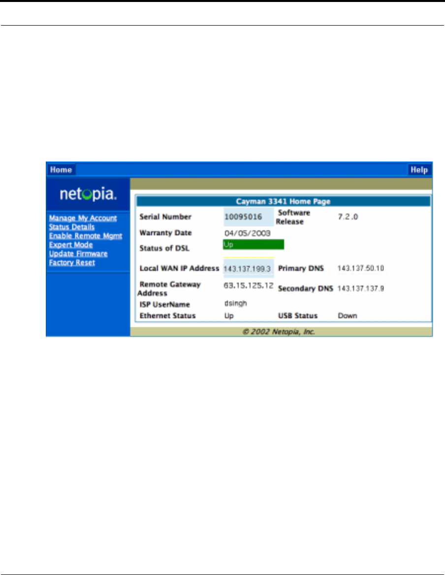
158
Home Page
The home page displays basic information about the Gateway. This includes
the ISP Username, Connection Status, Device Address, Remote Gateway
Address, DNS-1, and DNS-2. If you are not able to connect to the Internet,
verify the following:
Item Description
Local WAN IP
Address This is the negotiated address of the Gateway’s WAN interface.
This address is usually dynamically assigned.
Remote Gateway
Address This is the negotiated address of the remote router to which
this Gateway is connected.

159
Status of Connec-
tion ‘Waiting for DSL’ is displayed while the Gateway is training.
This should change to ‘Up’ within two minutes. If not, make
sure an RJ-11 cable is used, the Gateway is connected to the
correct wall jack, and the Gateway is not plugged into a micro
filter.
‘No Connection’ is displayed if the Gateway has trained but
failed the PPPoE login. This usually means an invalid user
name or password. Go to Expert Mode and change the PPPoE
name and password.
‘Up’ is displayed when the ADSL line is synched and the
PPPoE (or other connection method) session is established.
‘Down’ is displayed if the line connection fails.
ISP Username This should be the valid PPPoE username. If not, go to Expert
Mode and change to the correct username.
Device Address This is the negotiated address of the Gateway’s WAN interface.
This address is often dynamically assigned. Make sure this is a
valid address.
If this is not the correct assigned address, go to Expert Mode
and verify the PPPoE address has not been manually
assigned.
Device Gateway This is the negotiated address of the remote router. Make sure
this is a valid address.
If this is not the correct address, go to Expert Mode and verify
the address has not been manually assigned.
Primary DNS/
Secondary DNS These are the negotiated DNS addresses. Make sure they are
valid DNS addresses. (Secondary DNS is optional, and may
validly be blank (0.0.0.0).)
If these are not the correct addresses, go to Expert Mode and
verify the addresses have not been manually assigned.
Serial Number This is the unique serial number of your Gateway.
Ethernet Status This is the status of your Ethernet connection. If you are con-
necting via Ethernet, it should be Up.
USB Status This is the status of your USB connection (if equipped). If you
are connecting via USB, it should be Up.
Item Description

160
Software Release This is the version number of the current embedded software
in your Gateway.
Warranty Date This is the date that your Gateway was installed and enabled.
If all of the above seem correct, then access Expert Mode by clicking the
Expert Mode
link.
Item Description
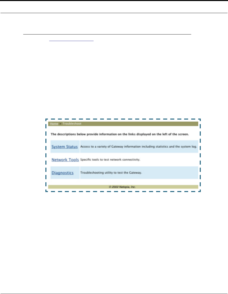
161
Button: Troubleshoot
Expert Mode
Expert Mode has advanced troubleshooting tools that are used to pinpoint
the exact source of a problem.
Clicking the Troubleshoot tab displays a page with links to System Status,
Network Tools, and Diagnostics.
•System Status: Displays an overall view of the system and its condition.
•Network Tools: Includes NSLookup, Ping and TraceRoute.
•Diagnostics: Runs a multi-layer diagnostic test that checks the LAN,
WAN, PPPoE, and other connection issues.
System Status
In the system status screen, there are several utilities that are useful for
troubleshooting. Some examples are given below.

162
Link: Ports: Ethernet
The Ethernet port selection shows the traffic sent and received on the
Ethernet interface. There should be frames and bytes on both the upstream
and downstream sides. If there are not, this could indicate a bad Ethernet
cable or no Ethernet connection. Below is an example:
Ethernet Driver Statistics - 10/100 Ethernet
Type: 100BASET
Port Status: Link up
General:
Transmit OK : 7862
Receive OK : 4454
Tx Errors : 0
Rx Errors : 0
Rx CRC Errors : 0
Rx Frame Errors : 0
Upper Layers:
Rx No Handler : 0
Rx No Message : 0
Rx Octets : 975576
Rx Unicast Pkts : 4156
Rx Multicast Pkts : 203
Tx Discards : 0
Tx Octets : 2117992
Tx Unicast Pkts : 3789
Tx Multicast Pkts : 4073
Ethernet driver statistics - USB
Port Status: Link down
General:
Transmit OK : 0
Receive OK : 0
Tx Errors : 0
Rx Errors : 0
Tx Octets : 0
Rx Octets : 0
Ethernet driver statistics - 10/100 Ethernet
Type: 100BASET
Port Status: Link up
General:
Transmit OK : 7863
Receive OK : 4458
Tx Errors : 0
Rx Errors : 0
Rx CRC Errors : 0
Rx Frame Errors : 0
Upper Layers:
Rx No Handler : 0
Rx No Message : 0
Rx Octets : 976327
Rx Unicast Pkts : 4159
Rx Multicast Pkts : 204
Tx Discards : 0

163
Link: Ports: DSL
The DSL port selection shows the state of the DSL line, whether it is up or
down and how many times the Gateway attempted to train. The state
should indicate ‘up’ for a working configuration. If it is not, check the DSL
cable and make sure it is plugged in correctly and not connected to a micro
filter. Below is an example:
ADSL Line State: Up
ADSL Startup Attempts: 5
ADSL Modulation: Unknown
Datapump Version: 3.22
Downstream Upstream
---------- ----------
SNR Margin: 18.6 14.0 dB
Line Attenuation: 0.4 4.0 dB
Errored Seconds: 14 3
Loss of Signal: 4 4
Loss of Frame: 0 0
CRC Errors: 0 0
Data Rate: 8000 800

164
Link: DSL: Circuit Configuration
The DSL Circuit Configuration screen shows the traffic sent and received
over the DSL line as well as the trained rate (upstream and downstream)
and the VPI/VCI. Verify traffic is being sent over the DSL line. If not, check
the cabling and make sure the Gateway is not connected to a micro filter.
Also verify the correct PVC is listed, which should be 0/35 (some providers
use other values, such as 8/35. Check with your provider). If not go to the
WAN setup and change the VPI/VCI to its correct value. Below is an exam-
ple:
ATM port status : Up
Rx data rate (bps) : 8000
Tx data rate (bps) : 800
ATM Virtual Circuits:
VCC # Type VPI VCI Encapsulation
---- ---- --- ----- --------------------------
1 PVC 8 35 PPP over Ethernet (LLC/SNAP encapsulation)
ATM Circuit Statistics:
Rx Frames : 17092 Tx Frames : 25078
Rx Octets : 905876 Tx Octets : 1329134
Rx Errors : 0 Tx Errors : 0
Rx Discards : 0 Tx Discards : 0
No Rx Buffers : 0 Tx Queue Full : 0

165
Link: System Log: Entire
The system log shows the state of the WAN connection as well as the
PPPoE session. Verify that the PPPoE session has been correctly estab-
lished and there are no failures. If there are error messages, go to the WAN
configuration and verify the settings. The following is an example of a suc-
cessful connection:
Message Log:
3/30/2003 19:22:58> ADSL detected
3/30/2003 19:23:4> ATM Connected
3/30/2003 19:23:4> ATM layer is up, cell delineation achieved
3/30/2003 19:23:4> ADSL connected
3/30/2003 19:23:8> PPP1 PPPoE Session is established.
3/30/2003 19:23:8> PPP PAP Authentication success
3/30/2003 19:23:8> PPP1: PPP IP address is 163.176.224.71
3/30/2003 19:23:8> PPP1: PPP Gateway IP address is 163.176.224.254
3/30/2003 19:23:8> PPP1: DNS Primary IP address is 163.176.4.10
3/30/2003 19:23:8> PPP1: DNS Secondary IP address is 163.176.4.32
3/30/2003 19:23:8> NAT/NAPT Session Start: VC# 0, WAN IP is 163.176.224.71
3/30/2003 19:23:8> NAPT: sesPVC0 session is up.
3/30/2003 19:23:9> PPP1 Session is up.
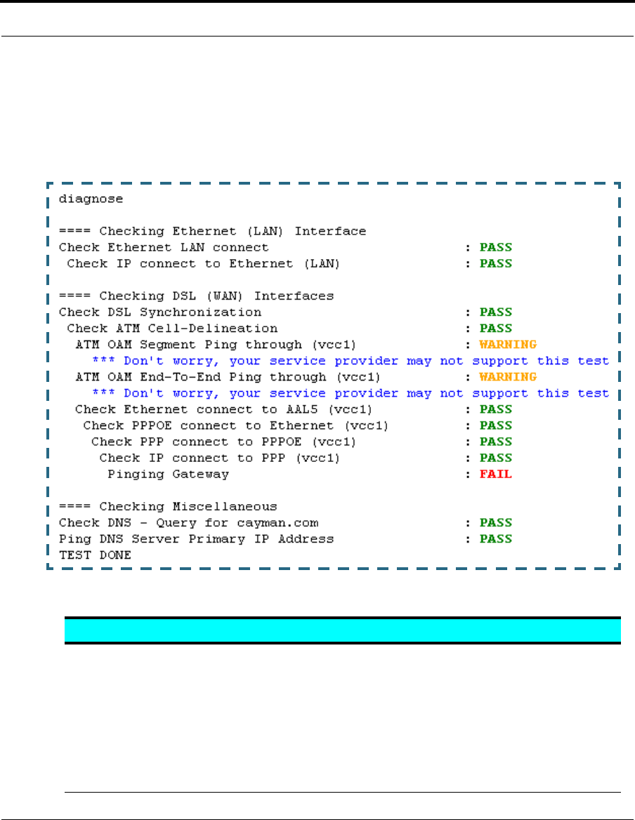
166
Diagnostics
The diagnostics section tests a number of different things at the same
time, including the DSL line, the Ethernet interface and the PPPoE session.
The following table summarizes the possible results.
CODE Description
PASS The test was successful.
FAIL The test was unsuccessful.
SKIPPED The test was skipped because a test on which it depended failed, or it was
not supported by the service provider equipment to which it is connected, or
it does not apply.
PENDING The test timed out without producing a result. Try running the test again.
WARNING The test was unsuccessful. The Service Provider equipment your Gateway
connects to may not support this test.
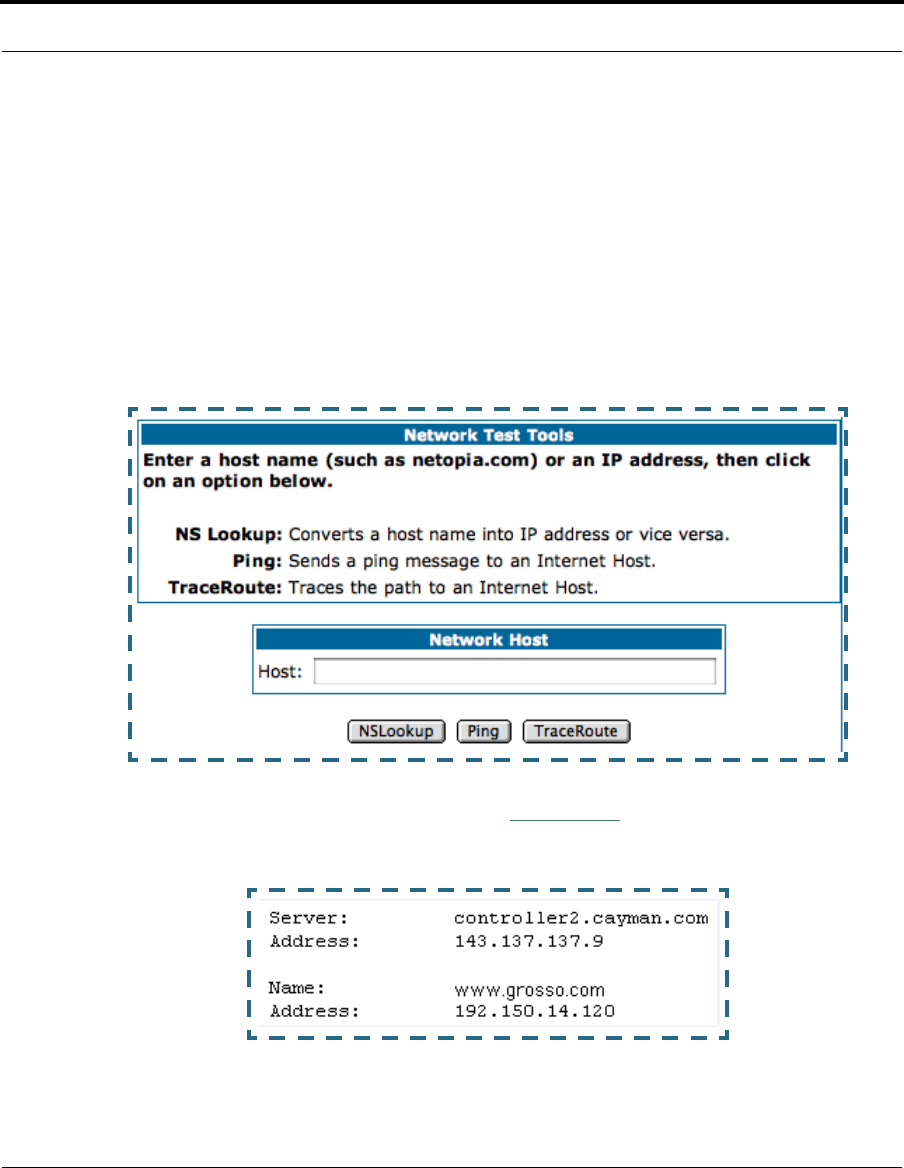
167
Network Tools
Three test tools are available from this page.
•NSLookup - converts a domain name to its IP address and vice versa.
•Ping - tests the “reachability” of a particular network destination by
sending an ICMP echo request and waiting for a reply.
•TraceRoute - displays the path to a destination by showing the number
of hops and the router addresses of these hops.
1. To use the NSLookup capability, type an address (domain name or IP
address) in the text box and click the
NSLookup
button
Example: Show the IP Address for grosso.com.
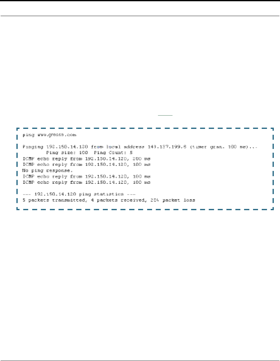
168
Result: The DNS Server doing the lookup is displayed in the Server: and
Address: fields. If the Name Server can find your entry in its table, it is
displayed in the Name: and Address: fields.
PING: The network tools section sends a PING from the Gateway to either
the LAN or WAN to verify connectivity. A PING could be either an IP address
(163.176.4.32) or Domain Name (www.netopia.com).
2. To use the Ping capability, type a destination address (domain name or IP
address) in the text box and click the
Ping
button.
Example: Ping to grosso.com.
Result: The host was reachable with four out of five packets sent.

169
Below are some specific tests:
3. To use the TraceRoute capability, type a destination address (domain
name or IP address) in the text box and click the
TraceRoute
button.
Action If PING is not successful, possible causes are:
From the Gateway's Network
Tools page:
Ping the internet default gateway
IP address DSL is down, DSL or ATM settings are incorrect;
Gateway’s IP address or subnet mask are wrong;
gateway router is down.
Ping an internet site by IP
address Gateway’s default gateway is incorrect, Gateway’s
subnet mask is incorrect, site is down.
Ping an internet site by name DNS is not properly configured on the Gateway;
configured DNS servers are down; site is down.
From a LAN PC:
Ping the Gateway’s LAN IP
address IP address and subnet mask of PC are not on the
same scheme as the Gateway; cabling or other
connectivity issue.
Ping the Gateway’s wan IP
address Default gateway on PC is incorrect.
Ping the Gateway’s internet
default gateway IP address NAT is off on the Gateway and the internal IP
addresses are private.
Ping an internet site by IP
address PC's subnet mask may be incorrect, site is down.
Ping an internet site by name DNS is not properly configured on the PC, config-
ured DNS servers are down, site is down.
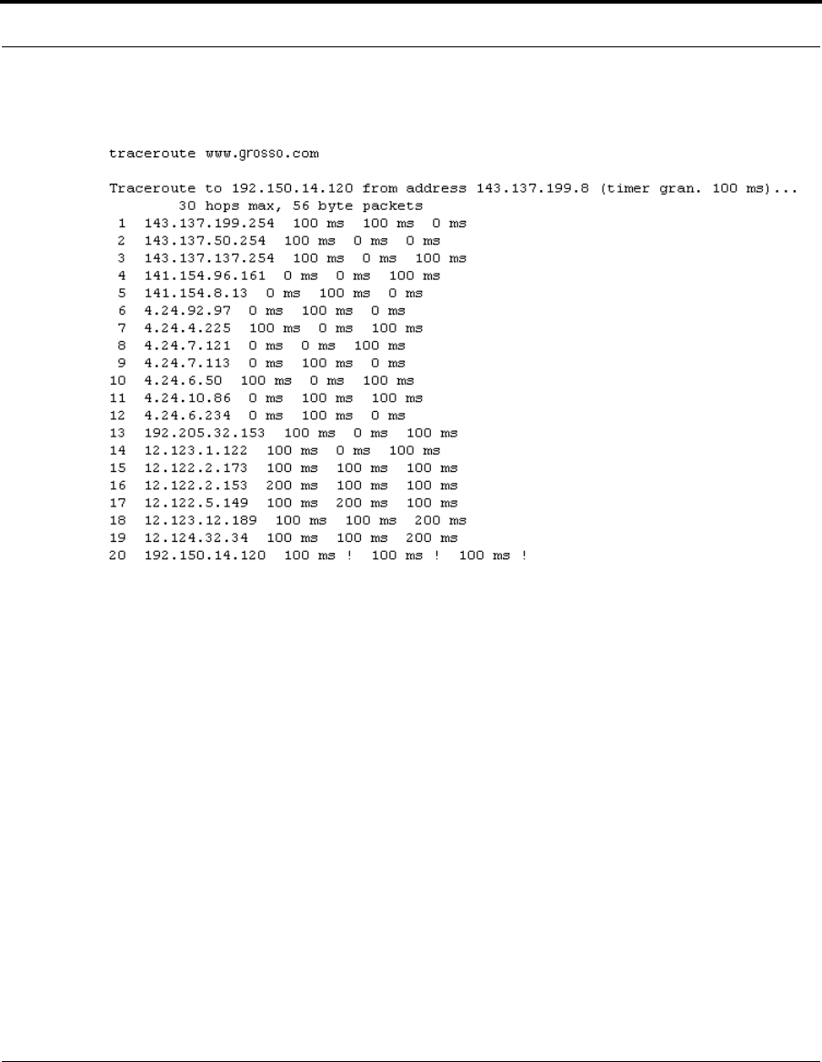
170
Example: Show the path to the grosso.com site.
Result: It took 20 hops to get to the grosso.com web site.

171
CHAPTER 6 Command Line
Interface
The Cayman Gateway operating software includes a command
line interface (CLI) that lets you access your Cayman Gateway
over a telnet connection. You can use the command line inter-
face to enter and update the unit’s configuration settings, mon-
itor its performance, and restart it.
This chapter covers the following topics:
•“Overview” on page 172
•“Starting and Ending a CLI Session” on page 175
•“Using the CLI Help Facility” on page 176
•“About SHELL Commands” on page 177
•“SHELL Commands” on page 178
•“About CONFIG Commands” on page 190
•“CONFIG Commands” on page 196

172
Overview
The CLI has two major command modes: SHELL and CONFIG.
Summary tables that list the commands are provided below.
Details of the entire command set follow in this section.
SHELL Commands
Command Status and/or Description
arp to send ARP request
atmping to send ATM OAM loopback
clear to erase all stored configuration information
configure to configure unit's options
diagnose to run self-test
download to download config file
exit to quit this shell
help to get more: “help all” or “help help”
install to download and program an image into flash
license to enter an upgrade key to add a feature
log to add a message to the diagnostic log
loglevel to report or change diagnostic log level
netstat to show IP information
nslookup to send DNS query for host
ping to send ICMP Echo request
quit to quit this shell
reset to reset subsystems
restart to restart unit
show to show system information
start to start subsystem
status to show basic status of unit
telnet to telnet to a remote host
traceroute to send traceroute probes
upload to upload config file
who to show who is using the shell

173
Overview
CONFIG Commands
Command
Verbs Status and/or Description
set Set configuration data
define Define environment data
delete Delete configuration list data
view View configuration data
script Print configuration data
help Help command option
save Save configuration data
Keywords
system Gateway’s system options
pppoe PPP over Ethernet options
dmt DMT ADSL options
atm ATM options (DSL only)
ip TCP/IP protocol options
dhcp Dynamic Host Configuration Protocol options
ethernet Ethernet options
ip-maps IPmaps options
nat-default Network Address Translation default options
dns Domain Name System options
bridge Bridge options
ppp Peer-to-Peer Protocol options
pinhole Pinhole options
security Security options
servers Internal Server options
state-insp Stateful Inspection Firewall options
validate Validate configuration settings
preferences Shell environment settings
snmp SNMP management options
xposed-addr Exposed Address options

174
Command
Utilities
top Go to top level of configuration mode
quit Exit from configuration mode; return to shell mode
exit Exit from configuration mode; return to shell mode

175
Starting and Ending a CLI Session
Starting and Ending a CLI Session
Open a telnet connection from a workstation on your network.
You initiate a telnet connection by issuing the following com-
mand from an IP host that supports telnet, for example, a per-
sonal computer running a telnet application such as NCSA
Telnet.
telnet <
ip_address
>
You must know the IP address of the Cayman Gateway before
you can make a telnet connection to it. By default, your Cayman
Gateway uses 192.168.1.254 as the IP address for its LAN
interface. You can use a Web browser to configure the Cayman
Gateway IP address.
Logging In
The command line interface log-in process emulates the log-in
process for a UNIX host. To logon, enter the username (either
admin or user), and your password.
•Entering the administrator password lets you display and
update all Cayman Gateway settings.
•Entering a user password lets you display (but not update)
Cayman Gateway settings.
When you have logged in successfully, the command line inter-
face lists the username and the security level associated with
the password you entered in the diagnostic log.
Ending a CLI Session
You end a command line interface session by typing quit from
the SHELL node of the command line interface hierarchy.

176
Saving Settings
In CONFIG mode, the save command saves the working copy of
the settings to the Gateway. The Gateway automatically vali-
dates its settings when you save and displays a warning mes-
sage if the configuration is not correct.
Using the CLI Help Facility
The help command lets you display on-line help for SHELL and
CONFIG commands. To display a list of the commands available
to you from your current location within the command line inter-
face hierarchy, enter help.
To obtain help for a specific CLI command, type help <com-
mand>. You can truncate the
help
command to
h
or a question
mark when you request help for a CLI command.

177
About SHELL Commands
About SHELL Commands
You begin in SHELL mode when you start a CLI session. SHELL
mode lets you perform the following tasks with your Cayman
Gateway:
•Monitor its performance
•Display and reset Gateway statistics
•Issue administrative commands to restart Cayman Gateway
functions
SHELL Prompt
When you are in SHELL mode, the CLI prompt is the name of
the Cayman Gateway followed by a right angle bracket (>). For
example, if you open a CLI connection to the Cayman Gateway
named “Coconut,” you would see
Coconut>
as your CLI prompt.
SHELL Command Shortcuts
You can truncate most commands in the CLI to their shortest
unique string. For example, you can use the truncated com-
mand
q
in place of the full
quit
command to exit the CLI. How-
ever, you would need to enter
rese
for the
reset
command,
since the first characters of
reset
are common to the
restart
command.
The only commands you cannot truncate are
restart
and
clear
.
To prevent accidental interruption of communications, you must
enter the
restart
and
clear
commands in their entirety.
You can use the Up and Down arrow keys to scroll backward
and forward through recent commands you have entered. Alter-
natively, you can use the
!!
command to repeat the last com-
mand you entered.

178
SHELL Commands
Common Commands
arp
nnn.nnn.nnn.nnn
Sends an Address Resolution Protocol (ARP) request to match
the
nnn.nnn.nnn.nnn
IP address to an Ethernet hardware
address.
clear [yes]
Clears the configuration settings in a Cayman Gateway. If you
do not use the optional yes qualifier, you are prompted to con-
firm the clear command.
configure
Puts the command line interface into Configure mode, which
lets you configure your Cayman Gateway with Config com-
mands. Config commands are described starting on page 173.
diagnose
Runs a diagnostic utility to conduct a series of internal checks
and loopback tests to verify network connectivity over each
interface on your Cayman Gateway. The console displays the
results of each test as the diagnostic utility runs. If one test is
dependent on another, the diagnostic utility indents its entry in
the console window. For example, the diagnostic utility indents
the Check IP connect to Ethernet (LAN) entry, since that test
will not run if the Check Ethernet LAN Connect test fails.

179
SHELL Commands
Each test generates one of the following result codes:
download [
server_address
] [
filename
] [confirm]
This command installs a file of configuration parameters into
the Cayman Gateway from a TFTP (Trivial File Transfer Protocol)
server. The TFTP server must be accessible on your Ethernet
network.
You can include one or more of the following arguments with
the download command. If you omit arguments, the console
prompts you for this information.
•The server_address argument identifies the IP address of
the TFTP server from which you want to copy the Cayman
Gateway configuration file.
•The filename argument identifies the path and name of the
configuration file on the TFTP server.
•If you include the optional confirm keyword, the download
begins as soon as all information is entered.
install [
server_address
] [
filename
] [confirm]
Downloads a new version of the Cayman Gateway operating
software from a TFTP (Trivial File Transfer Protocol) server, vali-
dates the software image, and programs the image into the
CODE Description
PASS The test was successful.
FAIL The test was unsuccessful.
SKIPPED The test was skipped because a test on which it
depended failed, or because the test did not
apply to your particular setup or model.
PENDING The test timed out without producing a result.
Try running the test again.

180
Cayman Gateway memory. After you install new operating soft-
ware, you must restart the Cayman Gateway.
The server_address argument identifies the IP address of
the TFTP server on which your Cayman Gateway operating soft-
ware is stored. The filename argument identifies the path
and name of the operating software file on the TFTP server.
If you include the optional keyword confirm, you will not be
prompted to confirm whether or not you want to perform the
operation.
license [key]
This command installs a software upgrade key. An upgrade key
is a purchased item, based on the serial number of the gate-
way.
log
message_string
Adds the message in the message_string argument to the
Cayman Gateway diagnostic log.
loglevel [
level
]
Displays or modifies the types of log messages you want the
Cayman Gateway to record. If you enter the loglevel com-
mand without the optional level argument, the command line
interface displays the current log level setting.
You can enter the loglevel command with the level argu-
ment to specify the types of diagnostic messages you want to
record. All messages with a level number equal to or greater
than the level you specify are recorded. For example, if you
specify loglevel 3, the diagnostic log will retain high-level infor-

181
SHELL Commands
mational messages (level 3), warnings (level 4), and failure
messages (level 5).
Use the following values for the level argument:
•1 or low – Low-level informational messages or greater;
includes trivial status messages.
•2 or medium – Medium-level informational messages or
greater; includes status messages that can help monitor net-
work traffic.
•3 or high – High-level informational messages or greater;
includes status messages that may be significant but do not
constitute errors.
•4 or warning – Warnings or greater; includes recoverable
error conditions and useful operator information.
•5 or failure – Failures; includes messages describing
error conditions that may not be recoverable.
netstat -i
Displays the IP interfaces for your Cayman Gateway.
netstat -r
Displays the IP routes stored in your Cayman Gateway.
nslookup {
hostname
|
ip_address
}
Performs a domain name system lookup for a specified host.
•The hostname argument is the name of the host for which
you want DNS information; for example,
nslookup klaatu
.
•The ip_address argument is the IP address, in dotted dec-
imal notation, of the device for which you want DNS informa-
tion.

182
ping [-s
size
] [-c
count
]{
hostname
|
ip_address
}
Causes the Cayman Gateway to issue a series of ICMP Echo
requests for the device with the specified name or IP address.
•The hostname argument is the name of the device you want
to ping; for example,
ping ftp.netopia.com
.
•The ip_address argument is the IP address, in dotted dec-
imal notation, of the device you want to locate. If a host
using the specified name or IP address is active, it returns
one or more ICMP Echo replies, confirming that it is accessi-
ble from your network.
•The
-s
size argument lets you specify the size of the ICMP
packet.
•The
-c
count argument lets you specify the number of ICMP
packets generated for the ping request. Values greater than
250 are truncated to 250.
You can use the ping command to determine whether a host-
name or IP address is already in use on your network. You can-
not use the ping command to ping the Cayman Gateway’s own
IP address.
quit
Exits the Cayman Gateway command line interface.
reset arp
Clears the Address Resolution Protocol (ARP) cache on your
unit.

183
SHELL Commands
reset crash
Clears crash-dump information, which identifies the contents of
the Cayman Gateway registers at the point of system malfunc-
tion.
reset dhcp server
Clears the DHCP lease table in the Cayman Gateway.
reset enet
Resets Ethernet statistics to zero
reset ipmap
Clears the IPMap table (NAT).
reset log
Rewinds the diagnostic log display to the top of the existing
Cayman Gateway diagnostic log. The reset log command does
not clear the diagnostic log. The next show log command will
display information from the beginning of the log file.
reset security-log
Clears the security monitoring log to make room to capture new
entries.
reset wan-users [all |
ip-address
]
This function disconnects the specified WAN User to allow for
other users to access the WAN. This function is only available if

184
the number of WAN Users is restricted and NAT is on. Use the
all parameter to disconnect all users. If you logon as Admin you
can disconnect any or all users. If you logon as User, you can
only disconnect yourself.
restart [
seconds
]
Restarts your Cayman Gateway. If you include the optional
seconds argument, your Cayman Gateway will restart when
the specified number of seconds have elapsed. You must enter
the complete restart command to initiate a restart.
show bridge interfaces
Displays bridge interfaces maintained by the Cayman Gateway.
show bridge table
Displays the bridging table maintained by the Cayman Gateway.
show crash
Displays the most recent crash information, if any, for your Cay-
man Gateway.
show dhcp server leases
Displays the DHCP leases stored in RAM by your Cayman Gate-
way.
show ip arp
Displays the Ethernet address resolution table stored in your
Cayman Gateway.

185
SHELL Commands
show ip igmp
Displays the contents of the IGMP Group Address table and the
IGMP Report table maintained by your Cayman Gateway.
show ip interfaces
Displays the IP interfaces for your Cayman Gateway.
show ip ipsec
Displays IPSec Tunnel statistics.
show ip firewall
Displays firewall statistics.
show ip routes
Displays the IP routes stored in your Cayman Gateway.
show ip state-insp
Displays whether stateful inspection is enabled on an interface
or not, exposed addresses and blocked packet statistics
because of stateful inspection.
show log
Displays blocks of information from the Cayman Gateway diag-
nostic log. To see the entire log, you can repeat the show log
command or you can enter show log all.

186
show memory [all]
Displays memory usage information for your Cayman Gateway.
If you include the optional
all
argument, your Cayman Gateway
will display a more detailed set of memory statistics.
show pppoe
Displays status information for each PPP socket, such as the
socket state, service names, and host ID values.
show rulesetlist
Displays all the available application hosting rules in the sys-
tem. See “Software Hosting” on page 104.
show status
Displays the current status of a Cayman Gateway, the device's
hardware and software revision levels, a summary of errors
encountered, and the length of time the Cayman Gateway has
been running since it was last restarted. Identical to the sta-
tus command.
telnet {
hostname
|
ip_address
} [
port
]
Lets you open a telnet connection to the specified host through
your Cayman Gateway.
•The hostname argument is the name of the device to which
you want to connect; for example,
telnet ftp.cayman.com
.
•The ip_address argument is the IP address, in dotted dec-
imal notation, of the device to which you want to connect.
•The port argument is the number of t he port over which
you want to open a telnet session.

187
SHELL Commands
upload [
server_address
] [
filename
] [confirm]
Copies the current configuration settings of the Cayman Gate-
way to a TFTP (Trivial File Transfer Protocol) server. The TFTP
server must be accessible on your Ethernet network. The
server_address argument identifies the IP address of the
TFTP server on which you want to store the Cayman Gateway
settings. The filename argument identifies the path and
name of the configuration file on the TFTP server. If you include
the optional confirm keyword, you will not be prompted to
confirm whether or not you want to perform the operation.
who
Displays the names of the current shell and PPP users.
WAN Commands
atmping vcc
n
[ segment | end-to-end ]
Lets you check the ATM connection reachability and network
connectivity. This command sends five Operations, Administra-
tion, and Maintenance (OAM) loopback calls to the specified
vpi/vci destination. There is a five second total timeout interval.
Use the segment argument to ping a neighbor switch.
Use the end-to-end argument to ping a remote end node.
reset dhcp client release [
vcc-id
]
Releases the DHCP lease the Cayman Gateway is currently
using to acquire the IP settings for the specified DSL port. The
vcc-id identifier is a letter in the range B-I. Enter the reset

188
dhcp client release without the variable to see the letter
assigned to each virtual circuit.
reset dhcp client renew [
vcc-id
]
Releases the DHCP lease the Cayman Gateway is currently
using to acquire the IP settings for the specified DSL port. The
vcc-id identifier is a letter in the range B-I. Enter the reset
dhcp client release without the variable to see the letter
assigned to each virtual circuit.
reset dsl
Resets any open DSL connection.
reset ppp
vccn
Resets the point-to-point connection over the specified virtual
circuit. This command only applies to virtual circuits that use
PPP framing.
show atm [all]
Displays ATM statistics for the Cayman Gateway. The optional
all argument displays a more detailed set of ATM statistics.
show dsl
Displays DSL port statistics, such as upstream and down-
stream connection rates and noise levels.

189
SHELL Commands
show ppp [{ stats | lcp | ipcp }]
Displays information about open PPP links. You can display a
subset of the PPP statistics by including an optional stats,
lcp, or ipcp argument for the show ppp command.
start ppp vccn
Opens a PPP link on the specified virtual circuit.

190
About CONFIG Commands
You reach the configuration mode of the command line inter-
face by typing
configure
(or any truncation of
configure
, such
as
con
or
config
) at the CLI SHELL prompt.
CONFIG Mode Prompt
When you are in CONFIG mode, the CLI prompt consists of the
name of the Cayman Gateway followed by your current node in
the hierarchy and two right angle brackets (>>). For example,
when you enter CONFIG mode (by typing
config
at the SHELL
prompt), the Coconut (top)>> prompt reminds you that you
are at the top of the CONFIG hierarchy. If you move to the ip
node in the CONFIG hierarchy (by typing ip at the CONFIG
prompt), the prompt changes to Coconut (ip)>> to identify
your current location.
Some CLI commands are not available until certain conditions
are met. For example, you must enable IP for an interface
before you can enter IP settings for that interface.
Navigating the CONFIG Hierarchy
•Moving from CONFIG to SHELL — You can navigate from
anywhere in the CONFIG hierarchy back to the SHELL level by
entering quit at the CONFIG prompt and pressing RETURN.
Dogzilla (top)>> quit
Dogzilla >
•Moving from
top
to a subnode — You can navigate from
the top node to a subnode by entering the node name (or the
significant letters of the node name) at the CONFIG prompt
and pressing RETURN. For example, you move to the IP subn-
ode by entering ip and pressing RETURN.

191
About CONFIG Commands
Dogzilla (top)>> ip
Dogzilla (ip)>>
As a shortcut, you can enter the significant letters of the node
name in place of the full node name at the CONFIG prompt. The
significant characters of a node name are the letters that
uniquely identify the node. For example, since no other CONFIG
node starts with I, you could enter one letter (“i”) to move to
the IP node.
•Jumping down several nodes at once — You can jump
down several levels in the CONFIG hierarchy by entering the
complete path to a node.
•Moving up one node — You can move up through the CON-
FIG hierarchy one node at a time by entering the up com-
mand.
•Jumping to the top node — You can jump to the top level
from anywhere in the CONFIG hierarchy by entering the top
command.
•Moving from one subnode to another — You can move
from one subnode to another by entering a partial path that
identifies how far back to climb.
•Moving from any subnode to any other subnode — You
can move from any subnode to any other subnode by enter-
ing a partial path that starts with a top-level CONFIG com-
mand.
•Scrolling backward and forward through recent com-
mands — You can use the Up and Down arrow keys to scroll
backward and forward through recent commands you have
entered. When the command you want appears, press Enter
to execute it.

192
Entering Commands in CONFIG Mode
CONFIG commands consist of keywords and arguments. Key-
words in a CONFIG command specify the action you want to
take or the entity on which you want to act. Arguments in a
CONFIG command specify the values appropriate to your site.
For example, the CONFIG command
set ip ethernet A
ip_address
consists of two keywords (
ip
, and
ethernet
A
) and one argu-
ment (ip_address). When you use the command to configure
your Gateway, you would replace the argument with a value
appropriate to your site.
For example:
set ip ethernet A 192.31.222.57

193
About CONFIG Commands
Guidelines: CONFIG Commands
The following table provides guidelines for entering and format-
ting CONFIG commands.
If a command is ambiguous or miskeyed, the CLI prompts you
to enter additional information. For example, you must specify
which virtual circuit you are configuring when you are setting up
a Cayman Gateway.
Command
component Rules for entering CONFIG commands
Command verbs CONFIG commands must start with a command verb
(set, view, delete).
You can truncate CONFIG verbs to three characters
(set, vie, del).
CONFIG verbs are case-insensitive. You can enter
“SET,” “Set,” or “set.”
Keywords Keywords are case-insensitive. You can enter “Ether-
net,” “ETHERNET,” or “ethernet” as a keyword without
changing its meaning.
Keywords can be abbreviated to the length that they are
differentiated from other keywords.
Argument Text Text strings can be as many as 64 characters long,
unless otherwise specified. In some cases they may be
as long as 255 bytes.
Special characters are represented using backslash
notation.
Text strings may be enclosed in double (“) or single (‘)
quote marks. If the text string includes an embedded
space, it must be enclosed in quotes.
Special characters are represented using backslash
notation.
Numbers Enter numbers as integers, or in hexadecimal, where so
noted.
IP addresses Enter IP addresses in dotted decimal notation (0 to
255).

194
Displaying Current Gateway Settings
You can use the
view
command to display the current CONFIG
settings for your Cayman Gateway. If you enter the
view
com-
mand at the top level of the CONFIG hierarchy, the CLI displays
the settings for all enabled functions. If you enter the
view
com-
mand at an intermediate node, you see settings for that node
and its subnodes.
Step Mode: A CLI Configuration Technique
The Cayman Gateway command line interface includes a step
mode to automate the process of entering configuration set-
tings. When you use the CONFIG step mode, the command line
interface prompts you for all required and optional information.
You can then enter the configuration values appropriate for your
site without having to enter complete CLI commands.
When you are in step mode, the command line interface
prompts you to enter required and optional settings. If a setting
has a default value or a current setting, the command line inter-
face displays the default value for the command in parenthe-
ses. If a command has a limited number of acceptable values,
those values are presented in brackets, with each value sepa-
rated by a vertical line. For example, the following CLI step com-
mand indicates that the default value is off and that valid
entries are limited to on and off.
option (off) [on | off]: on
You can accept the default value for a field by pressing the
Return key. To use a different value, enter it and press Return.
You can enter the CONFIG step mode by entering
set
from the
top node of the CONFIG hierarchy. You can enter step mode for
a particular service by entering
set
service_name. In step-

195
About CONFIG Commands
ping set mode (press Control-X <Return/Enter> to exit. For
example:
Dogzilla (top)>> set system
...
system
name (“Dogzilla”): Mycroft
Diagnostic Level (High): medium
Stepping mode ended.
Validating Your Configuration
You can use the validate CONFIG command to make sure
that your configuration settings have been entered correctly. If
you use the validate command, the Cayman Gateway verifies
that all required settings for all services are present and that
settings are consistent.
Dogzilla (top)>> validate
Error: Subnet mask is incorrect
Global Validation did not pass
inspection!
You can use the validate command to verify your configura-
tion settings at any time. Your Cayman Gateway automatically
validates your configuration any time you save a modified con-
figuration.

196
CONFIG Commands
This section describes the keywords and arguments for the var-
ious CONFIG commands.
DSL Commands
ATM Settings. You can use the CLI to set up each ATM virtual
circuit.
set atm option {on | off }
Enables the WAN interface of the Cayman Gateway to be config-
ured using the Asynchronous Transfer Mode (ATM) protocol.
set atm [vcc
n
] option {on | off }
Selects the virtual circuit for which further parameters are set.
Up to eight VCCs are supported; the maximum number is
dependent on your Cayman Operating System tier and the capa-
bilities that your Service Provider offers.
set atm [vcc
n
] qos service-class { cbr | ubr }
Sets the Quality of Service class for the specified virtual circuit
– Constant (cbr) or Unspecified (ubr) Bit Rate.
•ubr: No configuration is needed for UBR VCs. Leave the
default value 0 (maximum line rate).
•cbr: One parameter is required for CBR VCs. Enter the Peak
Cell Rate that applies to the VC. This value should be
between 1 and the line rate. You set this value according to
specifications defined by your service provider.

197
CONFIG Commands
set atm [vcc
n
] qos peak-cell-rate { 1 ...
n
}
If QoS class is set to cbr, then specifiy the peak-cell-rate that
should apply to the specified virtual circuit. This value should
be between 1 and the line rate.
set atm [vcc
n
] vpi { 0 ... 255 }
Select the virtual path identifier (vpi) for VCC n.
Your Service Provider will indicate the required vpi number.
set atm [vcc
n
] vci { 0 ... 65535 }
Select the virtual channel identifier (vci) for VCC n.
Your Service Provider will indicate the required vci number.
set atm [vccn] encap { ppp-vcmux | ppp-llc | ether-llc |
ip-llc | ppoe-vcmux | pppoe-llc }
Select the encapsulation mode for VCC n. The options are:
Your Service Provider will indicate the required encapsulation
mode.
ppp-vcmux PPP over ATM, VC-muxed
ppp-llc PPP over ATM, LLC-SNAP
ether-llc RFC-1483, bridged Ethernet, LLC-SNAP
ip-llc RFC-1483, routed IP, LLC-SNAP
pppoe-vcmux PPP over Ethernet, VC-muxed
pppoe-llc PPP over Ethernet, LLC-SNAP

198
set atm [vccn] pppoe-sessions { 1 ... 8 }
Select the number of PPPoE sessions to be configured for
VCC 1, up to a total of eight. The total number of pppoe-ses-
sions and PPPoE VCCs configured must be less than or equal
to eight.
Bridging Settings
Bridging lets the Cayman Gateway use MAC (Ethernet hard-
ware) addresses to forward non-TCP/IP traffic from one network
to another. When bridging is enabled, the Cayman Gateway
maintains a table of up to 512 MAC addresses. Entries that are
not used within 30 seconds are dropped. If the bridging table
fills up, the oldest table entries are dropped to make room for
new entries.
Virtual circuits that use IP framing cannot be bridged.
☛ NOTE:
For bridging in the 3341 (or any model with a USB
port), you cannot set the bridge option off, or
bridge ethernet option off; these are on by default
because of the USB port.
Common Commands
set bridge option {on | off }
Enables or disables bridging services in the Cayman Gateway.
You must enable bridging services within the Cayman Gateway
before you can enable bridging for a specific interface.

199
CONFIG Commands
set bridge ethernet option { on | off }
Enables or disables bridging services for the specified virtual
circuit using Ethernet framing.
set bridge dsl vcc
n
option { on | off }
Enables or disables bridging services for the specified DSL vir-
tual circuit.
DHCP Settings
As a Dynamic Host Control Protocol (DHCP) server, your Cay-
man Gateway can assign IP addresses and provide configura-
tion information to other devices on your network dynamically. A
device that acquires its IP address and other TCP/IP configura-
tion settings from the Cayman Gateway can use the information
for a fixed period of time (called the DHCP lease).
Common Commands
set dhcp option { off | server | relay-agent }
Enables or disables DHCP services in the Cayman Gateway.
You must enable DHCP services before you can enter other
DHCP settings for the Cayman Gateway.
If you turn off DHCP services and save the new configuration,
the Cayman Gateway clears its DHCP settings.
set dhcp start-address
ip_address
If you selected server, specifies the first address in the
DHCP address range. The Cayman Gateway can reserve a

200
sequence of up to 253 IP addresses within a subnet, beginning
with the specified address for dynamic assignment.
set dhcp end-address
ip_address
If you selected server, specifies the last address in the DHCP
address range.
set dhcp lease-time
lease-time
If you selected server, specifies the default length for DHCP
leases issued by the Cayman Gateway. Enter lease time in
dd:hh:mm:ss (day/hour/minute/second) format.
DMT Settings
DSL Commands
set dmt type [ lite | dmt | ansi | multi ]
Selects the type of Discrete Multitone (DMT) asynchronous digi-
tal subscriber line (ADSL) protocol to use for the WAN interface.
☛ NOTE:
dmt type is not supported for Annex B (335x) plat-
forms.
set dmt autoConfig [ off | on ]
Enables support for automatic VPI/VCI detection and configura-
tion. When set to on (the default), a pre-defined list of VPI/VCI
pairs are searched to find a valid configuration for your ADSL

201
CONFIG Commands
line. Entering a value for the VPI or VCI setting will disable this
feature.
set dmt wiringMode [ auto | tip_ring | A_A1 ]
(not supported on all models) This command configures the wir-
ing mode setting for your ADSL line. Selecting auto (the default)
causes the Gateway to detect which pair of wires (inner or outer
pair) are in use on your phone line. Specifying tip_ring forces
the inner pair to be used; and A_A1 the outer pair.
Domain Name System Settings
Domain Name System (DNS) is an information service for TCP/
IP networks that uses a hierarchical naming system to identify
network domains and the hosts associated with them. You can
identify a primary DNS server and one secondary server.
Common Commands
set dns domain-name
domain-name
Specifies the default domain name for your network. When an
application needs to resolve a host name, it appends the
default domain name to the host name and asks the DNS
server if it has an address for the “fully qualified host name.”
set dns primary-address
ip_address
Specifies the IP address of the primary DNS name server.

202
set dns secondary-address
ip_address
Specifies the IP address of the secondary DNS name server.
Enter
0.0.0.0
if your network does not have a secondary DNS
name server.
IP Settings
You can use the command line interface to specify whether
TCP/IP is enabled, identify a default Gateway, and to enter
TCP/IP settings for the Cayman Gateway LAN and WAN ports.
☛ NOTE:
For the DSL platform you must identify the virtual
PPP interface [vccn], a number from 1 to 8.
Common Settings
set ip option { on | off }
Enables or disables TCP/IP services in the Cayman Gateway.
You must enable TCP/IP services before you can enter other
TCP/IP settings for the Cayman Gateway. If you turn off TCP/IP
services and save the new configuration, the Cayman Gateway
clears its TCP/IP settings.

203
CONFIG Commands
DSL Settings
set ip dsl vccn address
ip_address
Assigns an IP address to the virtual circuit. Enter 0.0.0.0 if you
want the virtual circuit to obtain its IP address from a remote
DHCP server.
set ip dsl vccn broadcast
broadcast_address
Specifies the broadcast address for the TCP/IP network con-
nected to the virtual circuit. IP hosts use the broadcast address
to send messages to every host on your network simulta-
neously.
The broadcast address for most networks is the network num-
ber followed by 255. For example, the broadcast address for
the 192.168.1.0 network would be 192.168.1.255.
set ip dsl vccn netmask
netmask
Specifies the subnet mask for the TCP/IP network connected to
the virtual circuit. The subnet mask specifies which bits of the
32-bit binary IP address represents network information. The
default subnet mask for most networks is 255.255.255.0
(Class C subnet mask).
set ip dsl
vccn
restriction { admin-disabled | none }
Specifies restrictions on the types of traffic the Cayman Gate-
way accepts over the DSL virtual circuit. The admin-dis-
abled argument means that access to the device via telnet,
web, and SNMP is disabled. RIP and ICMP traffic is still
accepted. The none argument means that all traffic is
accepted.

204
set ip dsl vccn addr-mapping { on | off }
Specifies whether you want the Cayman Gateway to use net-
work address translation (NAT) when communicating with
remote routers. Address mapping lets you conceal details of
your network from remote routers. It also permits all LAN
devices to share a single IP address. By default, address map-
ping is turned “On”.
set ip dsl vccn rip-send { off | v1 | v2 | v1-compat | v2-MD5 }
Specifies whether the Cayman Gateway should use Routing
Information Protocol (RIP) broadcasts to advertise its routing
tables to other routers. RIP Version 2 (RIP-2) is an extension of
the original Routing Information Protocol (RIP-1) that expands
the amount of useful information in the RIP packets. While RIP-
1 and RIP-2 share the same basic algorithms, RIP-2 supports
several additional features, including inclusion of subnet masks
in RIP packets and implementation of multicasting instead of
broadcasting (which reduces the load on hosts which do not
support routing protocols. RIP-2 with MD5 authentication is an
extension of RIP-2 that increases security by requiring an
authentication key when routes are advertised.
Depending on your network needs, you can configure your Cay-
man Gateway to support RIP-1, RIP-2, or RIP-2MD5.
If you specify v2-MD5, you must also specify a rip-send-key.
Keys are ASCII strings with a maximum of 31 characters, and
must match the other router(s) keys for proper operation of
MD5 support.

205
CONFIG Commands
set ip dsl vccn rip-receive
{ off | v1 | v2 | v1-compat | v2-MD5 }
Specifies whether the Cayman Gateway should use Routing
Information Protocol (RIP) broadcasts to update its routing
tables with information received from other routers.
If you specify v2-MD5, you must also specify a rip-receive-
key. Keys are ASCII strings with a maximum of 31 characters,
and must match the other router(s) keys for proper operation of
MD5 support.
Ethernet Hub Settings
set ip ethernet option { on | off }
Enables or disables communications through the designated
Ethernet port in the Gateway. You must enable TCP/IP functions
for an Ethernet port before you can configure its network set-
tings.
☛ NOTE:
Currently, the only option is on; it cannot be set to
off.
set ip ethernet A address
ip_address
Assigns an IP address to the Cayman Gateway on the local area
network. The IP address you assign to the local Ethernet inter-
face must be unique on your network. By default, the Cayman
Gateway uses 192.168.1.254 as its LAN IP address.

206
set ip ethernet A broadcast
broadcast_address
Specifies the broadcast address for the local Ethernet inter-
face. IP hosts use the broadcast address to send messages to
every host on your network simultaneously.
The broadcast address for most networks is the network num-
ber followed by 255. For example, the broadcast address for
the 192.168.1.0 network would be 192.168.1.255.
set ip ethernet A netmask
netmask
Specifies the subnet mask for the local Ethernet interface. The
subnet mask specifies which bits of the 32-bit binary IP
address represent network information. The default subnet
mask for most networks is 255.255.255.0 (Class C subnet
mask).
set ip ethernet A restrictions { none | admin-disabled }
Specifies whether an administrator can open a telnet connec-
tion to a Cayman Gateway over the Ethernet interface to moni-
tor and configure the unit. The admin-disabled argument
means that access to the device via telnet, web, and SNMP is
disabled. On the WAN port, you can enable or disable adminis-
trator access or specify that the WAN port can only be used for
administrative traffic. By default, administrative restrictions are
off on the LAN, but Admin-Disabled is set for the WAN, meaning
an administrator can open a telnet connection.
set ip ethernet rip-send { off | v1 | v2 | v1-compat | v2-MD5 }
Specifies whether the Cayman Gateway should use Routing
Information Protocol (RIP) broadcasts to advertise its routing

207
CONFIG Commands
tables to other routers on your network. RIP Version 2 (RIP-2) is
an extension of the original Routing Information Protocol (RIP-1)
that expands the amount of useful information in the RIP pack-
ets. While RIP-1 and RIP-2 share the same basic algorithms,
RIP-2 supports several additional features, including inclusion
of subnet masks in RIP packets and implementation of multi-
casting instead of broadcasting (which reduces the load on
hosts which do not support routing protocols. RIP-2 with MD5
authentication is an extension of RIP-2 that increases security
by requiring an authentication key when routes are advertised.
If you specify v2-MD5, you must also specify a rip-send-key.
Keys are ASCII strings with a maximum of 31 characters, and
must match the other router(s) keys for proper operation of
MD5 support.
Depending on your network needs, you can configure your Cay-
man Gateway to support RIP-1, RIP-2, or RIP-2MD5.
set ip ethernet [ A | B ] rip-receive
{ off | v1 | v2 | v1-compat | v2-MD5 }
Specifies whether the Cayman Gateway should use Routing
Information Protocol (RIP) broadcasts to update its routing
tables with information received from other routers on your net-
work.
If you specify v2-MD5, you must also specify a rip-receive-
key. Keys are ASCII strings with a maximum of 31 characters,
and must match the other router(s) keys for proper operation of
MD5 support.

208
Default IP Gateway Settings
set ip gateway option { on | off }
Specifies whether the Cayman Gateway should send packets to
a default Gateway if it does not know how to reach the destina-
tion host.
set ip gateway interface { ip-address | ppp-vccn }
Specifies how the Cayman Gateway should route information to
the default Gateway. If you select ip-address, you must enter
the IP address of a host on a local or remote network. If you
specify ppp, the Cayman unit uses the default gateway being
used by the remote PPP peer.
IP-over-PPP Settings. Use the following commands to config-
ure settings for routing IP over a virtual PPP interface.
☛ NOTE:
For a DSL platform you must identify the virtual PPP
interface [vccn], a number from vcc1 to vcc8.
set ip ip-ppp [
vccn
] option { on | off }
Enables or disables IP routing through the virtual PPP interface.
By default, IP routing is turned off. You must enable IP routing
before you can enter other IP routing settings for the virtual PPP
interface. If you turn off IP routing and save the new configura-
tion, the Cayman Gateway clears IP routing settings

209
CONFIG Commands
set ip ip-ppp [
vccn
] address
ip_address
Assigns an IP address to the virtual PPP interface. If you spec-
ify an IP address other than 0.0.0.0, your Cayman Gateway will
not negotiate its IP address with the remote peer. If the remote
peer does not accept the IP address specified in the
ip_address argument as valid, the link will not come up.
The default value for the ip_address argument is 0.0.0.0,
which indicates that the virtual PPP interface will use the IP
address assigned to it by the remote peer. Note that the
remote peer must be configured to supply an IP address to your
Cayman Gateway if you enter 0.0.0.0 for the ip_address
argument.
set ip ip-ppp [
vccn
] peer-address
ip_address
Specifies the IP address of the peer on the other end of the PPP
link. If you specify an IP address other than 0.0.0.0, your Cay-
man Gateway will not negotiate the remote peer's IP address. If
the remote peer does not accept the address in the
ip_address argument as its IP address (typically because it
has been configured with another IP address), the link will not
come up.
The default value for the ip_address argument is 0.0.0.0,
which indicates that the virtual PPP interface will accept the IP
address returned by the remote peer. If you enter 0.0.0.0, the
peer system must be configured to supply this address.
set ip ip-ppp [
vccn
] restriction { admin-disabled | none }
Specifies restrictions on the types of traffic the Cayman Gate-
way accepts over the PPP virtual circuit. The admin-dis-

210
abled argument means that access to the device, via telnet,
web and SNMP is disabled. The none argument means that all
traffic is accepted.
set ip ip-ppp [
vccn
] addr-mapping { on | off }
Specifies whether you want the Cayman Gateway to use net-
work address translation (NAT) when communicating with
remote routers. Network address translation lets you conceal
details of your network from remote routers. By default,
address mapping is turned on.
set ip ip-ppp [
vccn
] rip-send
{ off | v1 | v2 | v1-compat | v2-MD5 }
Specifies whether the Cayman Gateway unit should use Routing
Information Protocol (RIP) broadcasts to advertise its routing
tables to routers on the other side of the PPP link. An extension
of the original Routing Information Protocol (RIP-1), RIP Version
2 (RIP-2) expands the amount of useful information in the pack-
ets. While RIP-1 and RIP-2 share the same basic algorithms,
RIP-2 supports several new features. For example, inclusion of
subnet masks in RIP packets and implementation of multicast-
ing instead of broadcasting. This last feature reduces the load
on hosts which do not support routing protocols. RIP-2 with
MD5 authentication is an extension of RIP-2 that increases
security by requiring an authentication key when routes are
advertised.
This command is only available when address mapping for the
specified virtual circuit is turned “off”.

211
CONFIG Commands
set ip ip-ppp [
vccn
] rip-receive
{ off | v1 | v2 | v1-compat | v2-MD5 }
Specifies whether the Cayman Gateway should use Routing
Information Protocol (RIP) broadcasts to update its routing
tables with information received from other routers on the other
side of the PPP link.
This command is only available when address mapping for the
specified virtual circuit is turned “off”.
Static ARP Settings. Your Cayman Gateway maintains a
dynamic Address Resolution Protocol (ARP) table to map IP
addresses to Ethernet (MAC) addresses. Your Cayman Gateway
populates this ARP table dynamically, by retrieving IP address/
MAC address pairs only when it needs them. Optionally, you can
define static ARP entries to map IP addresses to their corre-
sponding Ethernet MAC addresses. Unlike dynamic ARP table
entries, static ARP table entries do not time out.
You can configure as many as 16 static ARP table entries for a
Cayman Gateway. Use the following commands to add static
ARP entries to the Cayman Gateway static ARP table:
set ip static-arp ip-address
ip_address
Specifies the IP address for the static ARP entry. Enter an IP
address in the ip_address argument in dotted decimal for-
mat. The ip_address argument cannot be 0.0.0.0.
set ip static-arp ip-address
ip_address
hardware-address
MAC_address
Specifies the Ethernet hardware address for the static ARP
entry. Enter an Ethernet hardware address in the

212
MAC_address argument in
nn.nn.nn.nn.nn.nn
(hexadecimal)
format.
IGMP Forwarding
set ip igmp-forwarding [ off | on ]
Turns IP IGMP forwarding off or on. The default is off.
IPsec Passthrough
set ip ipsec-passthrough [ off | on ]
Turns IPsec client passthrough off or on. The default is on.
Static Route Settings
A static route identifies a manually configured pathway to a
remote network. Unlike dynamic routes, which are acquired and
confirmed periodically from other routers, static routes do not
time out. Consequently, static routes are useful when working
with PPP, since an intermittent PPP link may make maintenance
of dynamic routes problematic.
You can configure as many as 32 static IP routes for a Cayman
Gateway. Use the following commands to maintain static routes
to the Cayman Gateway routing table:
set ip static-routes destination-network
net_address
Specifies the network address for the static route. Enter a net-
work address in the net_address argument in dotted deci-
mal format. The net_address argument cannot be 0.0.0.0.

213
CONFIG Commands
set ip static-routes destination-network
net_address
netmask
netmask
Specifies the subnet mask for the IP network at the other end
of the static route. Enter the netmask argument in dotted deci-
mal format. The subnet mask associated with the destination
network must represent the same network class (A, B, or C) or
a lower class (such as a class C subnet mask for class B net-
work number) to be valid.
set ip static-routes destination-network
net_address
interface { ip-address | ppp-vccn }
Specifies the interface through which the static route is acces-
sible.
set ip static-routes destination-network
net_address
gateway-address
gate_address
Specifies the IP address of the Gateway for the static route. The
default Gateway must be located on a network connected to the
Cayman Gateway configured interface.
set ip static-routes destination-network
net_address
metric
integer
Specifies the metric (hop count) for the static route. The default
metric is 1. Enter a number from 1 to 15 for the integer argu-
ment to indicate the number of routers (actual or best guess) a
packet must traverse to reach the remote network.
You can enter a metric of 1 to indicate either:
•The remote network is one router away and the static route
is the best way to reach it;

214
•The remote network is more than one router away but the
static route should not be replaced by a dynamic route, even
if the dynamic route is more efficient.
set ip static-routes destination-network
net_address
rip-advertise [ SplitHorizon | Always | Never ]
Specifies whether the gateway should use Routing Information
Protocol (RIP) broadcasts to advertise to other routers on your
network and which mode to use. The default is SplitHorizon.
delete ip static-routes destination-network
net_address
Deletes a static route. Deleting a static route removes all infor-
mation associated with that route.
IPMaps Settings
set ip-maps name <
name
> internal-ip <
ip address
>
Specifies the name and static ip address of the LAN device to
be mapped.
set ip-maps name <
name
> external-ip <
ip address
>
Specifies the name and static ip address of the WAN device to
be mapped.
Up to 8 mapped static IP addresses are supported.

215
CONFIG Commands
Network Address Translation (NAT) Default
Settings
NAT default settings let you specify whether you want your Cay-
man Gateway to forward NAT traffic to a default server when it
doesn’t know what else to do with it. The NAT default host func-
tion is useful in situations where you cannot create a specific
NAT pinhole for a traffic stream because you cannot anticipate
what port number an application might use. For example, some
network games select arbitrary port numbers when a connec-
tion is being opened. By identifying your computer (or another
host on your network) as a NAT default server, you can specify
that NAT traffic that would otherwise be discarded by the Cay-
man Gateway should be directed to a specific hosts.
set nat-default mode { off | default-server |
ip-passthrough }
Specifies whether you want your Cayman Gateway to forward
unsolicited traffic from the WAN to a default server or an IP
passthrough host when it doesn’t know what else to do with it.
See “Default Server” on page 88 for more information.
set nat-default { address
ip_address
|
host-hardware-address
MAC_address
}
Specifies the IP address of the NAT default server or the hard-
ware (MAC) address of the IP passthrough host.

216
Network Address Translation (NAT) Pinhole
Settings
NAT pinholes let you pass specific types of network traffic
through the NAT interfaces on the Cayman Gateway. NAT pin-
holes allow you to route selected types of network traffic, such
as FTP requests or HTTP (Web) connections, to a specific host
behind the Cayman Gateway transparently.
To set up NAT pinholes, you identify the type(s) of traffic you
want to redirect by port number, and you specify the internal
host to which each specified type of traffic should be directed.
The following list identifies protocol type and port number for
common TCP/IP protocols:
•FTP (TCP 21)
•telnet (TCP 23)
•SMTP (TCP 25),
•TFTP (UDP 69)
•SNMP (TCP 161, UDP 161)
set pinhole name
name
Specifies the identifier for the entry in the router's pinhole
table. You can name pinhole table entries sequentially (1, 2, 3),
by port number (21, 80, 23), by protocol, or by some other
naming scheme.
set pinhole name
name
protocol-select { tcp | udp }
Specifies the type of protocol being redirected.
set pinhole name
name
external-port-start [ 0 - 49151 ]
Specifies the first port number in the range being translated.

217
CONFIG Commands
set pinhole name
name
external-port-end [ 0 - 49151 ]
Specifies the last port number in the range being translated.
set pinhole name
name
internal-ip
internal-ip
Specifies the IP address of the internal host to which traffic of
the specified type should be transferred.
set pinhole name
name
internal-port
internal-port
Specifies the port number your Cayman Gateway should use
when forwarding traffic of the specified type. Under most cir-
cumstances, you would use the same number for the external
and internal port.
PPPoE /PPPoA Settings
You can use the following commands to configure basic set-
tings, port authentication settings, and peer authentication set-
tings for PPP interfaces on your Cayman Gateway.
Configuring Basic PPP Settings.
☛ NOTE:
For the DSL platform you must identify the virtual
PPP interface [vccn], a number from 1 to 8.
set PPP module [vccn] option { on | off }
Enables or disables PPP on the Cayman Gateway.

218
set PPP module [vccn] auto-connect { on | off }
Supports manual mode required for some vendors. The default
on is not normally changed. If auto-connect is disabled (off),
you must manually start/stop a ppp connection.
set PPP module [vccn] mru
integer
Specifies the Maximum Receive Unit (MRU) for the PPP inter-
face. The integer argument can be any number between 128
and 1492 for PPPoE; 1500 otherwise.
set PPP module [vccn] magic-number { on | off }
Enables or disables LCP magic number negotiation.
set PPP module [vccn] protocol-compression { on | off }
Specifies whether you want the Cayman Gateway to compress
the PPP Protocol field when it transmits datagrams over the PPP
link.
set PPP module [vccn] lcp-echo-requests { on | off }
Specifies whether you want your Cayman Gateway to send LCP
echo requests. You should turn off LCP echoing if you do not
want the Cayman Gateway to drop a PPP link to a nonrespon-
sive peer.
set PPP module [vccn] failures-max
integer
Specifies the maximum number of Configure-NAK messages the
PPP module can send without having sent a Configure-ACK mes-
sage. The integer argument can be any number between 1 and
20.

219
CONFIG Commands
set PPP module [vccn] configure-max
integer
Specifies the maximum number of unacknowledged configura-
tion requests that your Cayman Gateway will send. The integer
argument can be any number between 1 and 10.
set PPP module [vccn] terminate-max
integer
Specifies the maximum number of unacknowledged termination
requests that your Cayman Gateway will send before terminat-
ing the PPP link. The integer argument can be any number
between 1 and 10.
set PPP module [vccn] restart-timer
integer
Specifies the number of seconds the Cayman Gateway should
wait before retransmitting a configuration or termination
request. The integer argument can be any number between 1
and 30.
set PPP module [vccn] connection-type
{ instant-on | always-on }
Specifies whether a PPP connection is maintained by the Cay-
man Gateway when it is unused for extended periods. If you
specify always-on, the Cayman Gateway never shuts down
the PPP link. If you specify instant-on, the Cayman Gateway
shuts down the PPP link after the number of seconds specified
in the time-out setting (below) if no traffic is moving over the
circuit.
set PPP module [vccn] time-out
integer
If you specified a connection type of instant-on, specifies
the number of seconds, in the range 30 - 3600, with a default

220
value of 300, the Cayman Gateway should wait for communica-
tion activity before terminating the PPP link.
Configuring Port Authentication. You can use the following
command to specify how your Cayman Gateway should respond
when it receives an authentication request from a remote peer.
The settings for port authentication on the local Cayman Gate-
way must match the authentication that is expected by the
remote peer. For example, if the remote peer requires CHAP
authentication and has a name and CHAP secret for the Cay-
man Gateway, you must enable CHAP and specify the same
name and secret on the Cayman Gateway before the link can be
established.
set PPP module [vccn] port-authentication
option [ off | on | pap-only | chap-only ]
username:
password:
Specifying on turns both PAP and CHAP on, or you can select
PAP or CHAP. Specify the username and password when port
authentication is turned on (both CHAP and PAP, CHAP or PAP.)
The username argument is 1- 255 alphanumeric characters.
The information you enter must match the username configured
in the PPP peer's authentication database.
The password argument is 1-32 alphanumeric characters. The
information you enter must match the password used by the
PPP peer.
Authentication must be enabled before you can enter other
information.

221
CONFIG Commands
Ethernet Port Settings
set ethernet ethernet A mode { auto | 100M-full |
100M-half | 10M-full | 10M-half }
Allows mode setting for the ethernet port. Only supported on
units without a LAN switch, or dual ethernet products (338x). In
the dual ethernet case, “ethernet B” would be specified for the
WAN port. The default is auto.
Command Line Interface Preference Settings
You can set command line interface preferences to customize
your environment.
set preference verbose { on | off }
set define verbose { on | off }
Specifies whether you want command help and prompting infor-
mation displayed. By default, the command line interface ver-
bose preference is turned off. If you turn it on, the command
line interface displays help for a node when you navigate to that
node.
set preference more
lines
set define more
lines
Specifies how many lines of information you want the command
line interface to display at one time. The lines argument speci-
fies the number of lines you want to see at one time. The range
is 1-65535. By default, the command line interface shows you
22 lines of text before displaying the prompt: More …[y|n] ?.

222
If you enter 100 for the
lines
argument, the command line
interface displays information as an uninterrupted stream
(which is useful for capturing information to a text file).
Port Renumbering Settings
If you use NAT pinholes to forward HTTP or telnet traffic through
your Cayman Gateway to an internal host, you must change the
port numbers the Cayman Gateway uses for its own configura-
tion traffic. For example, if you set up a NAT pinhole to forward
network traffic on Port 80 (HTTP) to another host, you would
have to tell the Cayman Gateway to listen for configuration con-
nection requests on a port number other than 80, such as
6080.
After you have changed the port numbers the Cayman Gateway
uses for its configuration traffic, you must use those port num-
bers instead of the standard numbers when configuring the Cay-
man Gateway. For example, if you move the router's Web
service to port “6080” on a box with a DNS name of “super-
box”, you would enter the URL http://superbox:6080 in a Web
browser to open the Cayman Gateway graphical user interface.
Similarly, you would have to configure your telnet application to
use the appropriate port when opening a configuration connec-
tion to your Cayman Gateway.
set servers web-http [ 0 - 65534 ]
Specifies the port number for HTTP (web) communication with
the Cayman Gateway. Because port numbers in the range 0-
1024 are used by other protocols, you should use numbers in
the range 2000-65534 when assigning new port numbers to
the Cayman Gateway web configuration interface. A setting of 0
(zero) will turn the server off.

223
CONFIG Commands
set servers telnet-tcp [ 0 - 65534 ]
Specifies the port number for telnet (CLI) communication with
the Cayman Gateway. Because port numbers in the range 0-
1024 are used by other protocols, you should use numbers in
the range 2000-65534 when assigning new port numbers to
the Cayman Gateway telnet configuration interface. A setting of
0 (zero) will turn the server off.
☛ NOTE:
You cannot specify a port setting of 0 (zero) for both
the web and telnet ports at the same time. This
would prevent you from accessing to the Gateway.
Security Settings
Security settings include the Firewall and IPSec parameters. All
of the security functionality is keyed.
Firewall Settings (for BreakWater Firewall)
set security firewall option [ ClearSailing | SilentRunning |
LANdLocked ]
The 3 settings for BreakWater are discussed in detail on page
page 111.

224
IPsec Settings
set security ipsec option [ off | on ]
Turns the IPsec option off or on. Default is off. See “IPSec” on
page 116 for more information.
SafeHarbour IPSec Settings
SafeHarbour VPN is a tunnel between the local network and
another geographically dispersed network that is intercon-
nected over the Internet. This VPN tunnel provides a secure,
cost-effective alternative to dedicated leased lines. Internet
Protocol Security (IPsec) is a series of services including
encryption, authentication, integrity, and replay protection.
Internet Key Exchange (IKE) is the key management protocol of
IPsec that establishes keys for encryption and decryption.
Because this VPN software implementation is built to these
standards, the other side of the tunnel can be either another
Cayman unit or another IPsec/IKE based security product. For
VPN you can choose to have traffic authenticated, encrypted, or
both.
When connecting the Cayman unit in a telecommuting scenario,
the corporate VPN settings will dictate the settings to be used
in the Cayman unit. If a parameter has not been specified from
the other end of the tunnel, choose the default unless you fully
understand the ramifications of your parameter choice.
set security ipsec nat-enable (off) {on | off}
This enables Network Address Translation (NAT) over the Safe-
Harbour tunnel.

225
CONFIG Commands
set security ipsec option (off) {on | off}
Turns on the SafeHarbour IPsec tunnel capability.
set security ipsec tunnels name "123"
The name of the tunnel can be quoted to allow special charac-
ters and embedded spaces.
set security ipsec tunnels name "123" tun-enable
(on) {on | off}
This enables this particular tunnel. Currently, one tunnel is sup-
ported.
set security ipsec tunnels name "123" dest-ext-address
ip-address
Specifies the IP address of the destination gateway.
set security ipsec tunnels name "123" dest-int-network
ip-address
Specifies the IP address of the destination computer or internal
network.
set security ipsec tunnels name "123" dest-int-netmask
netmask
Specifies the subnet mask of the destination computer or inter-
nal network. The subnet mask specifies which bits of the 32-bit
IP address represents network information. The default subnet
mask for most networks is 255.255.255.0 (class C subnet
mask).

226
set security ipsec tunnels name "123" encrypt-protocol
(ESP) { ESP | none }
See page 116 for details about SafeHarbour IPsec tunnel capa-
bility.
set security ipsec tunnels name "123" auth-protocol
(ESP) {AH | ESP | none}
See page 116 for details about SafeHarbour IPsec tunnel capa-
bility.
set security ipsec tunnels name "123" IKE-mode
pre-shared-key-type (hex) {ascii | hex}
See page 116 for details about SafeHarbour IPsec tunnel capa-
bility.
set security ipsec tunnels name "123" IKE-mode
pre-shared-key ("") {hex string}
See page 116 for details about SafeHarbour IPsec tunnel capa-
bility.
Example: 0x1234)
set security ipsec tunnels name "123" IKE-mode
neg-method (main) {main | aggressive}
See page 116 for details about SafeHarbour IPsec tunnel capa-
bility.
Note: Aggressive Mode is a little faster, but it does not provide
identity protection for negotiations nodes.

227
CONFIG Commands
set security ipsec tunnels name "123" IKE-mode
DH-group (1) { 1 | 2 | 5}
See page 116 for details about SafeHarbour IPsec tunnel capa-
bility.
set security ipsec tunnels name "123" IKE_mode
isakmp-SA-encrypt (DES) {DES | 3DES }
See page 116 for details about SafeHarbour IPsec tunnel capa-
bility.
set security ipsec tunnels name "123" isakmp-SA-hash
(MD5) {MD5 | SHA1}
See page 116 for details about SafeHarbour IPsec tunnel capa-
bility.
set security ipsec tunnels name "123"PFS-DH-group
(off) {off | 1 | 2 | 5 }
See page 116 for details about SafeHarbour IPsec tunnel capa-
bility.

228
Internet Key Exchange (IKE) Settings
The following four IPsec parameters configure the rekeying
event.
set security ipsec tunnels name "123" IKE-mode
ipsec-soft-mbytes (1000) {1-1000000}
set security ipsec tunnels name "123" IKE-mode
ipsec-soft-seconds (82800) {60-1000000}
set security ipsec tunnels name "123" IKE-mode
ipsec-hard-mbytes (1200) {1-1000000}
set security ipsec tunnels name "123" IKE-mode
ipsec-hard-seconds (86400) {60-1000000}
•The soft parameters designate when the system negotiates
a new key. For example, after 82800 seconds (23 hours) or
1 Gbyte has been transferred (whichever comes first) the key
will be renegotiated.
•The hard parameters indicate that the renegotiation must be
complete or the tunnel will be disabled. For example, 86400
seconds (24 hours) means that the renegotiation must be
complete within one day.
Both ends of the tunnel set parameters, and typically they will
be the same. If they are not the same, the rekey event will hap-
pen when the longest time period expires or when the largest
amount of data has been sent.

229
CONFIG Commands
Stateful Inspection
Stateful inspection options are accessed by the security state-
insp tag.
set security state-insp [ ip-ppp | dsl ] vcc
n
option [ off | on ]
set security state-insp ethernet [ A | B ] option [ off | on ]
Sets the stateful inspection option off or on on the specified
interface. This option is disabled by default. Stateful inspection
prevents unsolicited inbound access when NAT is disabled.
set security state-insp [ ip-ppp | dsl ] vcc
n
default-mapping [ off | on ]
set security state-insp ethernet [ A | B ]
default-mapping [ off | on ]
Sets stateful inspection default mapping to router option off or
on on the specified interface.
set security state-insp [ ip-ppp | dsl ] vcc
n
tcp-seq-diff
[ 0 - 65535 ]
set security state-insp ethernet [ A | B ] tcp-seq-diff
[ 0 - 65535 ]
Sets the acceptable TCP sequence difference on the specified
interface. The TCP sequence number difference maximum
allowed value is 65535. If the value of tcp-seq-diff is 0, it
means that this check is disabled.

230
set security state-insp [ ip-ppp | dsl ] vcc
n
deny-fragments [ off | on ]
set security state-insp ethernet [ A | B ]
deny-fragments [ off | on ]
Sets whether fragmented packets are allowed to be received or
not on the specified interface.
set security state-insp tcp-timeout [ 30 - 65535 ]
Sets the stateful inspection TCP timeout interval, in seconds.
set security state-insp udp-timeout [ 30 - 65535 ]
Sets the stateful inspection UDP timeout interval, in seconds.
set security state-insp xposed-addr exposed-address# "
n
"
Allows you to add an entry to the specified list, or, if the list
does not exist, creates the list for the stateful inspection fea-
ture.
Example:
set security state-insp xposed-addr exposed-
address# (?): 32
32 has been added to the xposed-addr list.
Sets the exposed list address number.

231
CONFIG Commands
set security state-insp xposed-addr
exposed-address# "
n
" start-ip
ip_address
Sets the exposed list range starting IP address, in dotted quad
format.
set security state-insp xposed-addr
exposed-address# "
n
" end-ip
ip_address
Sets the exposed list range ending IP address, in dotted quad
format.
32 exposed addresses can be created. The range for exposed
address numbers are from 1 through 32.
set security state-insp xposed-addr
exposed-address# "
n
" protocol [ tcp | udp | both | any ]
Sets the protocol for the stateful inspection feature for the
exposed address list. Accepted values for protocol are tcp,
udp, both, or any.
If protocol is not any, you can set port ranges:
set security state-insp xposed-addr
exposed-address# "
n
" start-port [ 1 - 65535 ]
set security state-insp xposed-addr
exposed-address# "
n
" end-port [ 1 - 65535 ]

232
SNMP Settings
The Simple Network Management Protocol (SNMP) lets a net-
work administrator monitor problems on a network by retrieving
settings on remote network devices. The network administrator
typically runs an SNMP management station program on a local
host to obtain information from an SNMP agent such as the
Cayman Gateway.
set snmp community read
name
Adds the specified name to the list of communities associated
with the Cayman Gateway. By default, the Cayman Gateway is
associated with the public community.
set snmp community trap
name
Adds the specified name to the list of communities associated
with the Cayman Gateway.
set snmp trap ip-traps
ip-address
Identifies the destination for SNMP trap messages. The ip-
address argument is the IP address of the host acting as an
SNMP console.
set snmp sysgroup contact
contact_info
Identifies the system contact, such as the name, phone num-
ber, beeper number, or email address of the person responsi-
ble for the Cayman Gateway. You can enter up to 255
characters for the contact_info argument. You must put the
contact_info argument in double-quotes if it contains
embedded spaces.

233
CONFIG Commands
set snmp sysgroup location
location_info
Identifies the location, such as the building, floor, or room num-
ber, of the Cayman Gateway. You can enter up to 255 charac-
ters for the location_info argument. You must put the
location_info argument in double-quotes if it contains
embedded spaces.
System Settings
You can configure system settings to assign a name to your
Cayman Gateway and to specify what types of messages you
want the diagnostic log to record.
set system name
name
Specifies the name of your Cayman Gateway. Each Cayman
Gateway is assigned a name as part of its factory initialization.
The default name for a Cayman Gateway consists of the word
“Cayman-XX” and the serial number of the device; for example,
Cayman-2E810700. A system name can be 1-63 characters
long. Once you have assigned a name to your Cayman Gateway,
you can enter that name in the Address text field of your browser
to open a connection to your Cayman Gateway.
☛ NOTE:
Some broadband cable-oriented Service Providers
use the System Name as an important identification
and support parameter. If your Gateway is part of
this type of network, do NOT alter the System Name
unless specifically instructed by your Service Pro-
vider.

234
set system diagnostic-level
{ off | low | medium | high | alerts | failures }
Specifies the types of log messages you want the Cayman
Gateway to record. All messages with a level equal to or greater
than the level you specify are recorded. For example, if you
specify set system diagnostic-level medium, the diagnostic log
will retain medium-level informational messages, alerts, and
failure messages. Specifying off turns off logging.
Use the following guidelines:
•low - Low-level informational messages or greater; includes
trivial status messages.
•medium - Medium-level informational messages or greater;
includes status messages that can help monitor network
traffic.
•high - High-level informational messages or greater;
includes status messages that may be significant but do not
constitute errors. The default.
•alerts - Warnings or greater; includes recoverable error
conditions and useful operator information.
•failures - Failures; includes messages describing error
conditions that may not be recoverable.
set system password { admin | user }
Specifies the administrator or user password for a Cayman
Gateway. When you enter the set system password com-
mand, you are prompted to enter the old password (if any) and
new password. You are prompted to repeat the new password
to verify that you entered it correctly the first time. To prevent
anyone from observing the password you enter, characters in
the old and new passwords are not displayed as you type them.

235
CONFIG Commands
For security, you cannot use the “step” method to set the sys-
tem password.
A password can be as many as eight characters. Passwords are
case-sensitive.
Passwords go into effect immediately. You do not have to
restart the Cayman Gateway for the password to take effect.
Assigning an administrator or user password to a Cayman Gate-
way does not affect communications through the device.
set system heartbeat { on | off }
protocol [ udp | tcp ]
port-client [ 1 - 65535 ]
ip-server
ip_address
port-server [ 1 - 65535 ]
url-server ("
server_name
")
interval (00:00:00:20)
contact-email ("
string
@
domain_name
")
location ("
string
"):
The heartbeat setting is used in conjunction with the configura-
tion server to broadcast contact and location information about
your Gateway. You can specify the protocol, port, IP-, port-, and
URL-server. The interval setting specifies the broadcast
update frequency. The contact-email setting is a quote-
enclosed text string giving an email address for the Gateway’s
administrator. The location setting is a text string allowing
you to specify your geographical or other location, such as “Bil-
lerica, MA.”

236
set system ntp
option [ off | on ]:
server-address (204.152.184.72)
alt-server-address (""):
time-zone [ -12 - 12 ]
update-period (60) [ 1 - 65535 ]:
Specifies the NTP server address, time zone, and how often the
Gateway should check the time from the NTP server. You can
leave the NTP server set to 204.152.184.72 and it will use the
server addresses known by the Gateway to update the time.
NTP time-zone of 0 is GMT time; options are -12 through 12 (+/
- 1 hour increments from GMT time). The last setting is for
specifying how often, in minutes, the Gateway should update
the clock.
Syslog
set system syslog option [ off | on ]
Enables or disables system syslog feature. If syslog option is
on, the following commands are available:
set system syslog host-nameip [
ip_address
|
hostname
]
Specifies the syslog server’s address either in dotted decimal
format or as a DNS name up to 64 characters.
set system syslog log-facility [ local0 ... local7 ]
Sets the UNIX syslog Facility. Acceptable values are local0
through local7.

237
CONFIG Commands
set system syslog log-violations [ off | on ]
Specifies whether violations are logged or ignored.
set system syslog log-accepted [ off | on ]
Specifies whether acceptances are logged or ignored.
set system syslog log-attempts [ off | on ]
Specifies whether connection attempts are logged or ignored.
Default
syslog
installation procedure
1. Access the router through the serial interface (if available) or
telnet to the product from the private LAN. DHCP server is
enabled on the LAN by default.
2. There will be a prompt to set up the administrative password.
The default Username is
admin
and this cannot be changed.
3. The product’s stateful inspection feature needs to be enabled
in order to prevent TCP, UDP and ICMP packets destined to
the router or the private hosts.
This can be done by entering the CONFIG interface.
• Type config
• Type the command to enable stateful inspection
set security state-insp eth B option on
• Type the command to enable the router to drop fragmented
packets
set security state-insp eth B deny-fragments on
4. Enabling syslog:
• Type config
• Type the command to enable syslog
set system syslog option on

238
• Set the IP Address of the syslog host
set system host-nameip <ip-addr>
(example: set system host-nameip 10.3.1.1)
• Enable/change the options you require
set system syslog log-facility local1
set system syslog log-violations on
set system syslog log-accepted on
set system syslog log-attempts on
5. Set NTP parameters
• Type config
• Set the time-zone – Default is 0 or GMT
set system ntp time-zone <zone>
(example: set system ntp time-zone –8)
• Set NTP server-address if necessary (default is
204.152.184.72)
set system ntp server-address <ip-addr>
(example:
set system server-address 204.152.184.73)
• Set alternate server address
set system ntp alt-server-address <ip-addr>
6. Type the command to save the configuration
• Type save
• Exit the configuration interface by typing
exit
• Restart the router by typing
restart
The router will reboot with the new configuration in effect.

239
CONFIG Commands
Wireless Settings (supported models)
set wireless option ( on | off )
Administratively enables or disables the wireless interface, if
available.
set wireless essid {
network_name
}
Specifies the wireless network id for the Gateway. A unique
essid is generated for each Gateway. You must set your wire-
less clients to connect to this exact id, which can be changed
to any 32-character string.
set wireless default-channel { 1...14 }
Specifies the wireless 2.4GHz sub channel on which the wire-
less Gateway will operate. For US operation, this is limited to
channels 1–11. Other countries vary; for example, Japan is
channel 14 only. The default channel in the US is 6. Channel
selection can have a significant impact on performance,
depending on other wireless activity in proximity to this AP.
Channel selection is not necessary at the clients; clients will
scan the available channels and look for APs using the same
essid as the client.
set wireless closed-system { on | off }
(if supported) When this setting is enabled, a client must know
the essid in order to connect or even see the wireless access
point. When disabled, a client may scan for available wireless
access points and will see this one. Enable this setting for
greater security. The default is on.

240
set wireless wep option { off | on }
(if supported) WEP is Wired Equivalent Privacy, a method of
encrypting data between the wireless Gateway and its clients. It
is strongly recommended to turn this on as it is the primary
way to protect your network and data from intruders. Note that
40bit is the same as 64bit and will work with either type of wire-
less client. The default is off.
A single key is selected (see default-key) for encryption of out-
bound/transmitted packets. The WEP-enabled client must have
the identical key, of the same length, in the identical slot (1..4)
as the wireless Gateway, in order to successfully receive and
decrypt the packet. Similarly, the client also has a ‘default’ key
that it uses to encrypt its transmissions. In order for the wire-
less Gateway to receive the client’s data, it must likewise have
the identical key, of the same length, in the same slot. For sim-
plicity, a wireless Gateway and its clients need only enter,
share, and use the first key.
set wireless wep default-keyid { 1...4 }
Specifies which WEP encryption key (of 4) the wireless Gateway
will use to transmit data. The client must have an identical
matching key, in the same numeric slot, in order to successfully
decode. Note that a client allows you to choose which of its
keys it will use to transmit. Therefore, you must have an identi-
cal key in the same numeric slot on the Gateway.
For simplicity, it is easiest to have both the Gateway and the cli-
ent transmit with the same key. The default is 1.

241
CONFIG Commands
set wireless wep encryption-key1-length
{40/64bit, 128bit, 256bit}
set wireless wep encryption-key2-length
{40/64bit, 128bit, 256bit}
set wireless wep encryption-key3-length
{40/64bit, 128bit, 256bit}
set wireless wep encryption-key4-length
{40/64bit, 128bit, 256bit}
Selects the length of each encryption key. 40bit encryption is
equivalent to 64bit encryption. The longer the key, the stronger
the encryption and the more difficult it is to break the encryp-
tion.
set wireless wep encryption-key1 {
hexadecimal digits
}
set wireless wep encryption-key2 {
hexadecimal digits
}
set wireless wep encryption-key3 {
hexadecimal digits
}
set wireless wep encryption-key4 {
hexadecimal digits
}
The encryption keys. Enter keys using hexadecimal digits. For
40/64bit encryption, you need 10 digits; 26 digits for 128bit,
and 58 digits for 256bit WEP. Valid hexadecimal characters are
0..9, a..f.
Example 40bit key: 02468ACE02.
Example 128bit key: 0123456789ABCDEF0123456789.
Example 256bit key:
592CA140F0A238B0C61AE162F592CA140F0A238B0C61AE162F21A09C.
You must set at least one of these keys, indicated by the
default-keyid.

242

243
CHAPTER 7 Glossary
10Base-T. IEEE 802.3 specification for Ethernet that uses
unshielded twisted pair (UTP) wiring with RJ-45 eight-conductor
plugs at each end. Runs at 10 Mbps.
100Base-T. IEEE 802.3 specification for Ethernet that uses
unshielded twisted pair (UTP) wiring with RJ-45 eight-conductor
plugs at each end. Runs at 100 Mbps.
-----A-----
ACK. Acknowledgment. Message sent from one network device
to another to indicate that some event has occurred. See NAK.
access rate. Transmission speed, in bits per second, of the cir-
cuit between the end user and the network.

244
adapter. Board installed in a computer system to provide net-
work communication capability to and from that computer sys-
tem.
address mask. See subnet mask.
ADSL. Asymmetric Digital Subscriber Line. Modems attached
to twisted pair copper wiring that transmit 1.5-9 Mbps down-
stream (to the subscriber) and 16 -640 kbps upstream,
depending on line distance.
AH. The Authentication Header provides data origin authentica-
tion, connectionless integrity, and anti-replay protection ser-
vices. It protects all data in a datagram from tampering,
including the fields in the header that do not change in transit.
Does not provide confidentiality.
ANSI. American National Standards Institute.
ASCII. American Standard Code for Information Interchange
(pronounced ASK-ee). Code in which numbers from 0 to 255
represent individual characters, such as letters, numbers, and
punctuation marks; used in text representation and communi-
cation protocols.
asynchronous communication. Network system that allows
data to be sent at irregular intervals by preceding each octet
with a start bit and following it with a stop bit. Compare syn-
chronous communication.
Auth Protocol. Authentication Protocol for IP packet header.
The three parameter values are None, Encapsulating Security
Payload (ESP) and Authentication Header (AH).

245
-----B-----
backbone. The segment of the network used as the primary
path for transporting traffic between network segments.
baud rate. Unit of signaling speed equal to the number of num-
ber of times per second a signal in a communications channel
varies between states. Baud is synonymous with bits per sec-
ond (bps) if each signal represents one bit.
binary. Numbering system that uses only zeros and ones.
bps. Bits per second. A measure of data transmission speed.
BRI. Basic Rate Interface. ISDN standard for provision of low-
speed ISDN services (two B channels (64 kbps each) and one
D channel (16 kbps)) over a single wire pair.
bridge. Device that passes packets between two network seg-
ments according to the packets' destination address.
broadcast. Message sent to all nodes on a network.
broadcast address. Special IP address reserved for simulta-
neous broadcast to all network nodes.
buffer. Storage area used to hold data until it can be for-
warded.
-----C-----
carrier. Signal suitable for transmission of information.
CCITT. Comité Consultatif International Télégraphique et
Téléphonique or Consultative Committee for International Tele-

246
graph and Telephone. An international organization responsible
for developing telecommunication standards.
CD. Carrier Detect.
CHAP. Challenge-Handshake Authentication Protocol. Security
protocol in PPP that prevents unauthorized access to network
services. See RFC 1334 for PAP specifications Compare PAP.
client. Network node that requests services from a server.
CPE. Customer Premises Equipment. Terminating equipment
such as terminals, telephones and modems that connects a
customer site to the telephone company network.
CO. Central Office. Typically a local telephone company facility
responsible for connecting all lines in an area.
compression. Operation performed on a data set that reduces
its size to improve storage or transmission rate.
crossover cable. Cable that lets you connect a port on one
Ethernet hub to a port on another Ethernet hub. You can order
an Ethernet crossover cable from Netopia, if needed.
CSU/DSU. Channel Service Unit/Data Service Unit. Device
responsible for connecting a digital circuit, such as a T1 link,
with a terminal or data communications device.
-----D-----
data bits. Number of bits used to make up a character.
datagram. Logical grouping of information sent as a network-
layer unit. Compare frame, packet.

247
DCE. Digital Communication Equipment. Device that connects
the communication circuit to the network end node (DTE). A
modem and a CSU/DSU are examples of a DCE.
dedicated line. Communication circuit that is used exclusively
to connect two network devices. Compare dial on demand.
DES. Data Encryption Standard is a 56-bit encryption algo-
rithm developed by the U.S. National Bureau of Standards (now
the National Institute of Standards and Technology).
3DES. Triple DES, with a 168 bit encryption key, is the most
accepted variant of DES.
DH Group. Diffie-Hellman is a public key algorithm used
between two systems to determine and deliver secret keys
used for encryption. Groups 1, 2 and 5 are supported. Also,
see Diffie-Hellman listing.
DHCP. Dynamic Host Configuration Protocol. A network configu-
ration protocol that lets a router or other device assign IP
addresses and supply other network configuration information
to computers on your network.
dial on demand. Communication circuit opened over standard
telephone lines when a network connection is needed.
Diffie-Hellman. A group of key-agreement algorithms that let
two computers compute a key independently without exchang-
ing the actual key. It can generate an unbiased secret key over
an insecure medium.
domain name. Name identifying an organization on the Inter-
net. Domain names consists of sets of characters separated by
periods (dots). The last set of characters identifies the type of

248
organization (.GOV, .COM, .EDU) or geographical location (.US,
.SE).
domain name server. Network computer that matches host
names to IP addresses in response to Domain Name System
(DNS) requests.
Domain Name System (DNS). Standard method of identifying
computers by name rather than by numeric IP address.
DSL. Digital Subscriber Line. Modems on either end of a single
twisted pair wire that delivers ISDN Basic Rate Access.
DTE. Data Terminal Equipment. Network node that passes
information to a DCE (modem) for transmission. A computer or
router communicating through a modem is an example of a DTE
device.
DTR. Data Terminal Ready. Circuit activated to indicate to a
modem (or other DCE) that the computer (or other DTE) is ready
to send and receive data.
-----E-----
echo interval. Frequency with which the router sends out echo
requests.
Enable. This toggle button is used to enable/disable the con-
figured tunnel.
encapsulation. Technique used to enclose information format-
ted for one protocol, such as AppleTalk, within a packet format-
ted for a different protocol, such as TCP/IP.
Encrypt Protocol. Encryption protocol for the tunnel session.

249
Parameter values supported include NONE or ESP.
encryption. The application of a specific algorithm to a data
set so that anyone without the encryption key cannot under-
stand the information.
ESP. Encapsulation Security Payload (ESP) header provides
confidentiality, data origin authentication, connectionless integ-
rity, anti-replay protection, and limited traffic flow confidentiality.
It encrypts the contents of the datagram as specified by the
Security Association. The ESP transformations encrypt and
decrypt portions of datagrams, wrapping or unwrapping the dat-
agram within another IP datagram. Optionally, ESP transforma-
tions may perform data integrity validation and compute an
Integrity Check Value for the datagram being sent. The com-
plete IP datagram is enclosed within the ESP payload.
Ethernet crossover cable. See crossover cable.
-----F-----
FCS. Frame Check Sequence. Data included in frames for error
control.
flow control. Technique using hardware circuits or control char-
acters to regulate the transmission of data between a computer
(or other DTE) and a modem (or other DCE). Typically, the
modem has buffers to hold data; if the buffers approach capac-
ity, the modem signals the computer to stop while it catches up
on processing the data in the buffer. See CTS, RTS, xon/xoff.
fragmentation. Process of breaking a packet into smaller units
so that they can be sent over a network medium that cannot
transmit the complete packet as a unit.

250
frame. Logical grouping of information sent as a link-layer unit.
Compare datagram, packet.
FTP. File Transfer Protocol. Application protocol that lets one IP
node transfer files to and from another node.
FTP server. Host on network from which clients can transfer
files.
-----H-----
Hard MBytes. Setting the Hard MBytes parameter forces the
renegotiation of the IPSec Security Associations (SAs) at the
configured Hard MByte value.
The value can be configured between 1 and 1,000,000 MB and
refers to data traffic passed.
Hard Seconds. Setting the Hard Seconds parameter forces
the renegotiation of the IPSec Security Associations (SAs) at
the configured Hard Seconds value. The value can be config-
ured between 60 and 1,000,000 seconds.
A tunnel will start the process of renegotiation at the soft
threshold and renegotiation must happen by the hard limit or
traffic over the tunnel is terminated.
hardware handshake. Method of flow control using two con-
trol lines, usually Request to Send (RTS) and Clear to Send
(CTS).
header. The portion of a packet, preceding the actual data,
containing source and destination addresses and error-check-
ing fields.

251
HMAC. Hash-based Message Authentication Code
hop. A unit for measuring the number of routers a packet has
passed through when traveling from one network to another.
hop count. Distance, measured in the number of routers to be
traversed, from a local router to a remote network. See metric.
hub. Another name for a repeater. The hub is a critical network
element that connects everything to one centralized point. A
hub is simply a box with multiple ports for network connections.
Each device on the network is attached to the hub via an Ether-
net cable.
-----I-----
IKE. Internet Key Exchange protocol provides automated key
management and is a preferred alternative to manual key man-
agement as it provides better security. Manual key manage-
ment is practical in a small, static environment of two or three
sites. Exchanging the key is done through manual means.
Because IKE provides automated key exchange, it is good for
larger, more dynamic environments.
INSPECTION. The best option for Internet communications
security is to have an SMLI firewall constantly inspecting the
flow of traffic: determining direction, limiting or eliminating
inbound access, and verifying down to the packet level that the
network traffic is only what the customer chooses. The Cayman
Gateway works like a network super traffic cop, inspecting and
filtering out undesired traffic based on your security policy and
resulting configuration.
interface. A connection between two devices or networks.

252
internet address. IP address. A 32-bit address used to route
packets on a TCP/IP network. In dotted decimal notation, each
eight bits of the 32-bit number are presented as a decimal num-
ber, with the four octets separated by periods.
IPCP. Internet Protocol Control Protocol. A network control pro-
tocol in PPP specifying how IP communications will be config-
ured and operated over a PPP link.
IPSEC. A protocol suite defined by the Internet Engineering
Task Force to protect IP traffic at packet level. It can be used for
protecting the data transmitted by any service or application
that is based on IP, but is commonly used for VPNs.
ISAKMP. Internet Security Association and Key Management
Protocol is a framework for creating connection specific param-
eters. It is a protocol for establishing, negotiating, modifying,
and deleting SAs and provides a framework for authentication
and key exchange. ISAKMP is a part of the IKE protocol.
-----K-----
Key Management . The Key Management algorithm manages
the exchange of security keys in the IPSec protocol architec-
ture. SafeHarbour supports the standard
Internet Key
Exchange (IKE)
-----L-----
LCP. Link Control Protocol. Protocol responsible for negotiating
connection configuration parameters, authenticating peers on
the link, determining whether a link is functioning properly, and
terminating the link. Documented in RFC 1331.

253
LQM Link Quality Monitoring. Optional facility that lets PPP
make policy decisions based on the observed quality of the link
between peers. Documented in RFC 1333.
loopback test. Diagnostic procedure in which data is sent from
a devices's output channel and directed back to its input chan-
nel so that what was sent can be compared to what was
received.
-----M-----
magic number. Random number generated by a router and
included in packets it sends to other routers. If the router
receives a packet with the same magic number it is using, the
router sends and receives packets with new random numbers
to determine if it is talking to itself.
MD5. A 128-bit, message-digest, authentication algorithm used
to create digital signatures. It computes a secure, irreversible,
cryptographically strong hash value for a document. Less
secure than variant SHA-1.
metric. Distance, measured in the number of routers a packet
must traverse, that a packet must travel to go from a router to a
remote network. A route with a low metric is considered more
efficient, and therefore preferable, to a route with a high metric.
See hop count.
modem. Modulator/demodulator. Device used to convert a dig-
ital signal to an analog signal for transmission over standard
telephone lines. A modem at the other end of the connection
converts the analog signal back to a digital signal.
MRU. Maximum Receive Unit. The maximum packet size, in
bytes, that a network interface will accept.

254
MTU. Maximum Transmission Unit. The maximum packet size,
in bytes, that can be sent over a network interface.
MULTI-LAYER. The Open System Interconnection (OSI) model
divides network traffic into seven distinct levels, from the Physi-
cal (hardware) layer to the Application (software) layer. Those in
between are the Presentation, Session, Transport, Network,
and Data Link layers. Simple first and second generation fire-
wall technologies inspect between 1 and 3 layers of the 7 layer
model, while our SMLI engine inspects layers 2 through 7.
-----N-----
NAK. Negative acknowledgment. See ACK.
Name. The Name parameter refers to the name of the config-
ured tunnel. This is mainly used as an identifier for the adminis-
trator. The Name parameter is an ASCII and is limited to 31
characters. The tunnel name is the only IPSec parameter that
does not need to match the peer gateway.
NCP. Network Control Protocol.
Negotiation Method. This parameter refers to the method
used during the Phase I key exchange, or IKE process. SafeHar-
bour supports Main or Aggressive Mode. Main mode requires 3
two-way message exchanges while Aggressive mode only
requires 3 total message exchanges.
null modem. Cable or connection device used to connect two
computing devices directly rather than over a network.

255
-----P-----
packet. Logical grouping of information that includes a header
and data. Compare frame, datagram.
PAP. Password Authentication Protocol. Security protocol within
the PPP protocol suite that prevents unauthorized access to
network services. See RFC 1334 for PAP specifications. Com-
pare CHAP.
parity. Method of checking the integrity of each character
received over a communication channel.
Peer External IP Address. The Peer External IP Address is the
public, or routable IP address of the remote gateway or VPN
server you are establishing the tunnel with.
Peer Internal IP Network. The Peer Internal IP Network is the
private, or Local Area Network (LAN) address of the remote
gateway or VPN Server you are communicating with.
Peer Internal IP Netmask. The Peer Internal IP Netmask is the
subnet mask of the Peer Internal IP Network.
PFS Enable. Enable Perfect Forward Secrecy. PFS forces a DH
negotiation during Phase II of IKE-IPSec SA exchange. You can
disable this or select a DH group 1, 2, or 5. PFS is a security
principle that ensures that any single key being compromised
will permit access to only data protected by that single key. In
PFS, the key used to protect transmission of data must not be
used to derive any additional keys. If the key was derived from
some other keying material, that material must not be used to
derive any more keys.

256
PING. Packet INternet Groper. Utility program that uses an
ICMP echo message and its reply to verify that one network
node can reach another. Often used to verify that two hosts can
communicate over a network.
PPP. Point-to-Point Protocol. Provides a method for transmitting
datagrams over serial router-to-router or host-to-network con-
nections using synchronous or asynchronous circuits.
Pre-Shared Key. The Pre-Shared Key is a parameter used for
authenticating each side. The value can be an ASCII or Hex and
a maximum of 64 characters.
Pre-Shared Key Type. The Pre-Shared Key Type classifies the
Pre-Shared Key. SafeHarbour supports
ASCII
or
HEX
types
protocol. Formal set of rules and conventions that specify how
information can be exchanged over a network.
PSTN. Public Switched Telephone Network.
-----R-----
repeater. Device that regenerates and propagates electrical
signals between two network segments. Also known as a hub.
RFC. Request for Comment. Set of documents that specify the
conventions and standards for TCP/IP networking.
RIP. Routing Information Protocol. Protocol responsible for dis-
tributing information about available routes and networks from
one router to another.
RJ-45. Eight-pin connector used for 10BaseT (twisted pair
Ethernet) networks.

257
route. Path through a network from one node to another. A
large internetwork can have several alternate routes from a
source to a destination.
routing table. Table stored in a router or other networking
device that records available routes and distances for remote
network destinations.
-----S-----
SA Encrypt Type. SA Encryption Type refers to the symmetric
encryption type. This encryption algorithm will be used to
encrypt each data packet. SA Encryption Type values supported
include
DES
and
3DES
.
SA Hash Type. SA Hash Type refers to the Authentication
Hash algorithm used during SA negotiation. Values supported
include
MD5 SHA1
. N/A will display if NONE is chose for Auth
Protocol.
Security Association. From the IPSEC point of view, an SA is
a data structure that describes which transformation is to be
applied to a datagram and how. The SA specifies:
•The authentication algorithm for AH and ESP
•The encryption algorithm for ESP
•The encryption and authentication keys
•Lifetime of encryption keys
•The lifetime of the SA
•Replay prevention sequence number and the replay bit table
An arbitrary 32-bit number called a Security Parameters Index
(SPI), as well as the destination host’s address and the IPSEC
protocol identifier, identify each SA. An SPI is assigned to an SA

258
when the SA is negotiated. The SA can be referred to by using
an SPI in AH and ESP transformations. SA is unidirectional. SAs
are commonly setup as bundles, because typically two SAs are
required for communications. SA management is always done
on bundles (setup, delete, relay).
serial communication. Method of data transmission in which
data bits are transmitted sequentially over a communication
channel
SHA-1. An implementation of the U.S. Government Secure
Hash Algorithm; a 160-bit authentication algorithm.
Soft MBytes. Setting the Soft MBytes parameter forces the
renegotiation of the IPSec Security Associations (SAs) at the
configured Soft MByte value. The value can be configured
between
1 and 1,000,000 MB
and refers to data traffic passed.
If this value is not achieved, the Hard MBytes parameter is
enforced.
Soft Seconds. Setting the Soft Seconds parameter forces the
renegotiation of the IPSec Security Associations (SAs) at the
configured Soft Seconds value. The value can be configured
between 60 and 1,000,000 seconds.
SPI . The Security Parameter Index is an identifier for the
encryption and authentication algorithm and key. The SPI indi-
cates to the remote firewall the algorithm and key being used to
encrypt and authenticate a packet. It should be a unique num-
ber greater than 255.
STATEFUL. The Cayman Gateway monitors and maintains the
state of any network transaction. In terms of network request-
and-reply, state consists of the source IP address, destination
IP address, communication ports, and data sequence. The Cay-

259
man Gateway processes the stream of a network conversation,
rather than just individual packets. It verifies that packets are
sent from and received by the proper IP addresses along the
proper communication ports in the correct order and that no
imposter packets interrupt the packet flow. Packet filtering mon-
itors only the ports involved, while the Cayman Gateway ana-
lyzes the continuous conversation stream, preventing session
hijacking and denial of service attacks.
static route. Route entered manually in a routing table.
subnet mask. A 32-bit address mask that identifies which bits
of an IP address represent network address information and
which bits represent node identifier information.
synchronous communication. Method of data communica-
tion requiring the transmission of timing signals to keep PPP
peers synchronized in sending and receiving blocks of data.
-----T-----
telnet. IP protocol that lets a user on one host establish and
use a virtual terminal connection to a remote host.
twisted pair. Cable consisting of two copper strands twisted
around each other. The twisting provides protection against
electromagnetic interference.
-----U-----
UTP. Unshielded twisted pair cable.

260
-----V-----
VJ. Van Jacobson. Abbreviation for a compression standard
documented in RFC 1144.
-----W-----
WAN. Wide Area Network. Private network facilities, usually
offered by public telephone companies but increasingly avail-
able from alternative access providers (sometimes called Com-
petitive Access Providers, or CAPs), that link business network
nodes.
WWW. World Wide Web.

261
Description
CHAPTER 8 Technical
Specifications
and Safety
Information
Description
Dimensions: 13.5 cm (w) x 13.5 cm (d) x 3.5 cm (h)
5.25” (w) x 5.25” (d) x 1.5” (h)
Communications interfaces: The Netopia 3300 Series Gateways
have an RJ-11 jack for DSL line connections or an RJ-45 jack for cable/DSL
modem connections and 1 or 4–port 10/100Base-T Ethernet switch for your
LAN connections. Some models have a USB port that can be used to
connect to your PC; in some cases, the USB port also serves as the power
source. Some models contain an 802.11b wireless LAN transmitter.

262
Power requirements
■12 VDC input
■1.0 amps
■USB-powered models only: For Use with Listed I.T.E. Only
Environment
Operating temperature: 0° to +40° C
Storage temperature: 0° to +70° C
Relative storage humidity: 20 to 80% noncondensing
Software and protocols
Software media: Software preloaded on internal flash memory; field
upgrades done via download to internal flash memory via TFTP or web
upload.
Routing: TCP/IP Internet Protocol Suite, RIP
WAN support: PPPoE, DHCP, static IP address
Security: PAP, CHAP, UI password security, IPsec
Management/configuration methods: HTTP (Web server), Telnet
Diagnostics: Ping, event logging, routing table displays, statistics
counters, web-based management

263
Agency approvals
Agency approvals
North America
Safety Approvals:
■United States – UL 60950, Third Edition
■Canada – CSA: CAN/CSA-C22.2 No. 60950-00
EMC:
■United States – FCC Part 15 Class B
■Canada – ICES-003
Telecom:
■United States – FCC Part 68
■Canada – CS-03
International
Safety Approvals:
■Low Voltage (European directive) 73/23
■EN60950 (Europe)
EMI Compatibility:
■89/336/EEC (European directive)
■EN55022:1994 CISPR22 Class B
■EN300 386 V1.2.1 (non-wireless products)
■EN 301-489 (wireless products)
Regulatory notices
European Community. This Netopia product conforms to the
European Community CE Mark standard for the design and manufacturing of
information technology equipment. This standard covers a broad area of
product design, including RF emissions and immunity from electrical
disturbances.

264
The Netopia 3300 Series complies with the following EU directives:
■Low Voltage, 73/23/EEC
■EMC Compatibility, 89/336/EEC, conforming to EN 55 022
Manufacturer’s Declaration of
Conformance
☛ Warnings:
This is a Class B product. In a domestic environment this prod-
uct may cause radio interference, in which case the user may
be required to take adequate measures. Adequate measures
include increasing the physical distance between this product
and other electrical devices.
Changes or modifications to this unit not expressly approved by
the party responsible for compliance could void the user’s
authority to operate the equipment.
United States. This equipment has been tested and found to comply
with the limits for a Class B digital device, pursuant to Part 15 of the FCC
Rules. These limits are designed to provide reasonable protection against
harmful interference in a residential installation. This equipment generates,
uses, and can radiate radio frequency energy and, if not installed and used
in accordance with the instructions, may cause harmful interference to radio
communications. However, there is no guarantee that interference will not
occur in a particular installation. If this equipment does cause harmful
interference to radio or television reception, which can be determined by
turning the equipment off and on, the user is encouraged to try to correct
the interference by one or more of the following measures:
■Reorient or relocate the receiving antenna.
■Increase the separation between the equipment and receiver.
■Connect the equipment into an outlet on a circuit different from that to

265
Manufacturer’s Declaration of Conformance
which the receiver is connected.
■Consult the dealer or an experienced radio TV technician for help.
Service requirements. In the event of equipment malfunction, all
repairs should be performed by our Company or an authorized agent. Under
FCC rules, no customer is authorized to repair this equipment. This
restriction applies regardless of whether the equipment is in or our of
warranty. It is the responsibility of users requiring service to report the need
for service to our Company or to one of our authorized agents. Service can
be obtained at Netopia, Inc., 6001 Shellmound Street, Emeryville,
California, 94608. Telephone: 510-597-5400.
☛ Important
This product was tested for FCC compliance under conditions
that included the use of shielded cables and connectors
between system components. Changes or modifications to this
product not authorized by the manufacturer could void your
authority to operate the equipment.
Canada. This Class B digital apparatus meets all requirements of the
Canadian Interference -Causing Equipment Regulations.
Cet appareil numérique de la classe B respecte toutes les exigences du
Réglement sur le matériel brouilleur du Canada.
Declaration for Canadian users
NOTICE: The Canadian Industry Canada label identifies certified
equipment. This certification means that the equipment meets certain
telecommunications network protective, operation, and safety
requirements. The Department does not guarantee the equipment will
operate to the user’s satisfaction.

266
Before installing this equipment, users should ensure that it is permissible
to be connected to the facilities of the local telecommunications
company. The equipment must also be installed using an acceptable
method of connection. In some cases, the company’s inside wiring
associated with a single line individual service may be extended by means
of a certified connector assembly (telephone extension cord). The
customer should be aware that compliance with the above conditions may
not prevent degradation of service in some situations.
Repairs to the certified equipment should be made by an authorized
Canadian maintenance facility designated by the supplier. Any repairs or
alterations made by the user to this equipment, or equipment
malfunctions, may give the telecommunications company cause to
request the user to disconnect the equipment.
Users should ensure for their own protection that the electrical ground
connections of the power utility, telephone lines, and internal metallic
water pipe system, if present, are connected together. This precaution
may be particularly important in rural areas.
Caution
Users should not attempt to make such connections themselves, but should
contact the appropriate electric inspection authority, or electrician, as
appropriate.
The Ringer Equivalence Number (REN) assigned to each terminal device
provides an indication of the maximum number of terminals allowed to be
connected to a telephone interface. The termination on an interface may
consist of any combination of devices subject only to the requirement that
the sum of the Ringer Equivalence Numbers of all the devices does not
exceed 5.

267
Important Safety Instructions
Important Safety Instructions
Australian Safety Information
The following safety information is provided in conformance with Australian
safety requirements:
Caution
DO NOT USE BEFORE READING THE INSTRUCTIONS: Do not connect the
Ethernet ports to a carrier or carriage service provider’s telecommunica-
tions network or facility unless: a) you have the written consent of the
network or facility manager, or b) the connection is in accordance with a
connection permit or connection rules.
Connection of the Ethernet ports may cause a hazard or damage to the tele-
communication network or facility, or persons, with consequential liability for
substantial compensation.
Caution
■The direct plug-in power supply serves as the main power disconnect;
locate the direct plug-in power supply near the product for easy access.
■For use only with CSA Certified Class 2 power supply, rated 12VDC,
1.0A.
Telecommunication installation cautions
■Never install telephone wiring during a lightning storm.
■Never install telephone jacks in wet locations unless the jack is
specifically designed for wet locations.
■Never touch uninsulated telephone wires or terminals unless the
telephone line has been disconnected at the network interface.
■Use caution when installing or modifying telephone lines.
■Avoid using a telephone (other than a cordless type) during an electrical
storm. There may be a remote risk of electric shock from lightning.
■Do not use the telephone to report a gas leak in the vicinity of the leak.

268
FCC Part 68 Information
FCC Requirements
1. The Federal Communications Commission (FCC) has established Rules
which permit this device to be directly connected to the telephone
network. Standardized jacks are used for these connections. This
equipment should not be used on party lines or coin phones.
2. If this device is malfunctioning, it may also be causing harm to the
telephone network; this device should be disconnected until the source
of the problem can be determined and until repair has been made. If
this is not done, the telephone company may temporarily disconnect
service.
3. The telephone company may make changes in its technical operations
and procedures; if such changes affect the compatibility or use of this
device, the telephone company is required to give adequate notice of
the changes. You will be advised of your right to file a complaint with the
FCC.
4. If the telephone company requests information on what equipment is
connected to their lines, inform them of:
a. The telephone number to which this unit is connected.
b. The ringer equivalence number. [0.XB]
c. The USOC jack required. [RJ11C]
d. The FCC Registration Number. [XXXUSA-XXXXX-XX-E]
Items (b) and (d) are indicated on the label. The Ringer Equivalence
Number (REN) is used to determine how many devices can be
connected to your telephone line. In most areas, the sum of the REN's
of all devices on any one line should not exceed five (5.0). If too many
devices are attached, they may not ring properly.
FCC Statements
a) This equipment complies with Part 68 of the FCC rules and the
requirements adopted by the ACTA. On the bottom of this equipment is a
label that contains, among other information, a product identifier in the
format US:AAAEQ##TXXXX. If requested, this number must be provided to
the telephone company.

269
FCC Part 68 Information
b) List all applicable certification jack Universal Service Order Codes
(“USOC”) for the equipment: RJ11.
c) A plug and jack used to connect this equipment to the premises wiring
and telephone network must comply with the applicable FCC Part 68 rules
and requirements adopted by the ACTA. A compliant telephone cord and
modular plug is provided with this product. It is designed to be connected to
a compatible modular jack that is also compliant. See installation
instructions for details.
d) The REN is used to determine the number of devices that may be
connected to a telephone line. Excessive RENs on a telephone line may
result in the devices not ringing in response to an incoming call. In most but
not all areas, the sum of RENs should not exceed five (5.0). To be certain of
the number of devices that may be connected to a line, as determined by
the total RENs, contact the local telephone company. For products approved
after July 23, 2002, the REN for this product is part of the product identifier
that has the format US:AAAEQ##TXXXX. The digits represented by ## are
the REN without a decimal point (e.g., 03 is a REN of 0.3). For earlier
products, the REN is separately shown on the label.
e) If this equipment, the Netopia 3300 Series router, causes harm to the
telephone network, the telephone company will notify you in advance that
temporary discontinuance of service may be required. But if advance notice
isn’t practical, the telephone company will notify the customer as soon as
possible. Also, you will be advised of your right to file a complaint with the
FCC if you believe it is necessary.
f) The telephone company may make changes in its facilities, equipment,
operations or procedures that could affect the operation of the equipment. If
this happens the telephone company will provide advance notice in order for
you to make necessary modifications to maintain uninterrupted service.
g) If trouble is experienced with this equipment, the Netopia 3300 Series
router, for repair or warranty information, please contact:
Netopia Technical Support
510-597-5400
www.netopia.com.
If the equipment is causing harm to the telephone network, the telephone
company may request that you disconnect the equipment until the problem
is resolved.
h) This equipment not intended to be repaired by the end user. In case of
any problems, please refer to the troubleshooting section of the Product
User Manual before calling Netopia Technical Support.

270
i) Connection to party line service is subject to state tariffs. Contact the
state public utility commission, public service commission or corporation
commission for information.
j) If your home has specially wired alarm equipment connected to the
telephone line, ensure the installation of this Netopia 3300 Series router
does not disable your alarm equipment. If you have questions about what
will disable alarm equipment, consult your telephone company or qualified
installer.
RF Exposure Statement:
NOTE: Installation of the wireless models must maintain at least 20 cm
between the wireless router and any body part of the user to be in
compliance with FCC RF exposure guidelines.
Electrical Safety Advisory
Telephone companies report that electrical surges, typically lightning
transients, are very destructive to customer terminal equipment connected
to AC power sources. This has been identified as a major nationwide
problem. Therefore it is advised that this equipment be connected to AC
power through the use of a surge arrestor or similar protection device.

271
Index
Symbols
!! command 177
A
Access the GUI 47
Address resolution table 184
Administrative restrictions 209
Administrator password 47,
109, 175
Arguments, CLI 192
ARP
Command 178, 187
Authentication 220
Authentication trap 232
B
Bridging 198
Broadcast address 203, 206
C
CLI 171
!! command 177
Arguments 192
Command shortcuts 177
Command truncation 191
Configuration mode 190
Keywords 192
Navigating 190
Prompt 177, 190
Restart command 177
SHELL mode 177
View command 194
Command
ARP 178, 187
Ping 182
Telnet 186
Command line interface (see
CLI)
Community 232
Compression, protocol 218
CONFIG
Command List 173
Configuration mode 190
D
Default IP address 47
denial of service 259
DHCP 199
DHCP lease table 183
Diagnostic log 183, 185
Level 234
Diagnostics 39
DNS 201
DNS Proxy 38
Documentation conventions 13
Domain Name System
(DNS) 201
E
Echo request 218
Embedded Web Server 39
Ethernet address 198
Ethernet statistics 183

272
F
Feature Keys
Obtaining 142
firewall 185
FTP 215
H
Hardware address 198
hijacking 259
Hop count 213
How To
Configure a SafeHarbour
VPN 117
Configure Multiple Static IP
Addresses 117
HTTP traffic 222
I
ICMP Echo 182
Install 136
IP address 203, 205
Default 47
IP interfaces 185
IP routes 185
IPSec Tunnel 185
K
Keywords, CLI 192
L
LCP echo request 218
Link
Install Software 136
Quickstart 56, 58, 72
Local Area Network 38
Location, SNMP 232
Log 185
Logging in 175
M
Magic number 218
Memory 186
Metric 213
N
Nameserver 201
NAT 40, 210, 215
Traffic rules 91
NAT Default Server 44
Netmask 206
Network Address
Translation 40
Network Test Tools 39
NSLookup 40
P
PAP 36
Password 109
Administrator 47, 109, 175
User 47, 109, 175
Ping 40
Ping command 182
Pinholes 43, 215
Planning 78
Port authentication 220
Port forwarding 43
Port renumbering 222

273
PPP 188
PPPoE 36
Primary nameserver 201
Prompt, CLI 177, 190
Protocol compression 218
Q
qos peak-cell-rate 197
qos service-class 196
R
Restart 184
Restart command 177
Restart timer 219
Restrictions 209
RIP 204, 206
Routing Information Protocol
(RIP) 204, 206
S
Secondary nameserver 201
Security log 134
Set bncp command 196, 197,
198
Set bridge commands 198
Set dns commands 201
Set ip static-routes
commands 212
Set ppp module port authentica-
tion command 220
Set preference more
command 221
Set preference verbose
command 221
set security state-insp 229
Set servers command 222
Set servers telnet-tcp
command 223
Set snmp sysgroup location
command 233
Set snmp traps authentification-
traps ip-address command 232
Set system diagnostic-level
command 234
Set system heartbeat
command 235
Set system name command 233
Set system NTP command 236
Set system password
command 234
set system syslog 236
Set wireless option
command 239
SHELL
Command Shortcuts 177
Commands 177
Prompt 177
SHELL level 190
SHELL mode 177
Show ppp 188
Simple Network Management
Protocol (SNMP) 232
SMTP 215
SNMP 94, 215, 232
Stateful Inspection 125
stateful inspection 185
Static route 212
Step mode 194
Subnet mask 206

274
Syslog 101
System contact, SNMP 232
System diagnostics 234
T
Telnet 175, 215
Telnet command 186
Telnet traffic 222
TFTP 215
TFTP server 180
Toolbar 51
TraceRoute 40, 167
Trap 232
Trivial File Transfer
Protocol 179
Truncation 191
U
User name 175
User password 47, 109, 175
V
set atm 196, 197
View command 194
VPN
IPSec Pass Through 44
IPSec Tunnel
Termination 46
W
Wide Area Network 36
Wireless 61

Cayman 3300 series by Netopia
Netopia, Inc.
6001 Shellmound Street
Emeryville, CA 94608
July, 2003