ARRIS 45010 802.11b/g User Manual User Guide
ARRIS Group, Inc. 802.11b/g User Guide
UserManual.wiki
>
ARRIS
>
45010 User Manual
User Guide
Navigation menu
Upload a User Manual
Namespaces
Wiki Guide
HTML
PDF
Info
Views
User Manual
Discussion / Help
Navigation


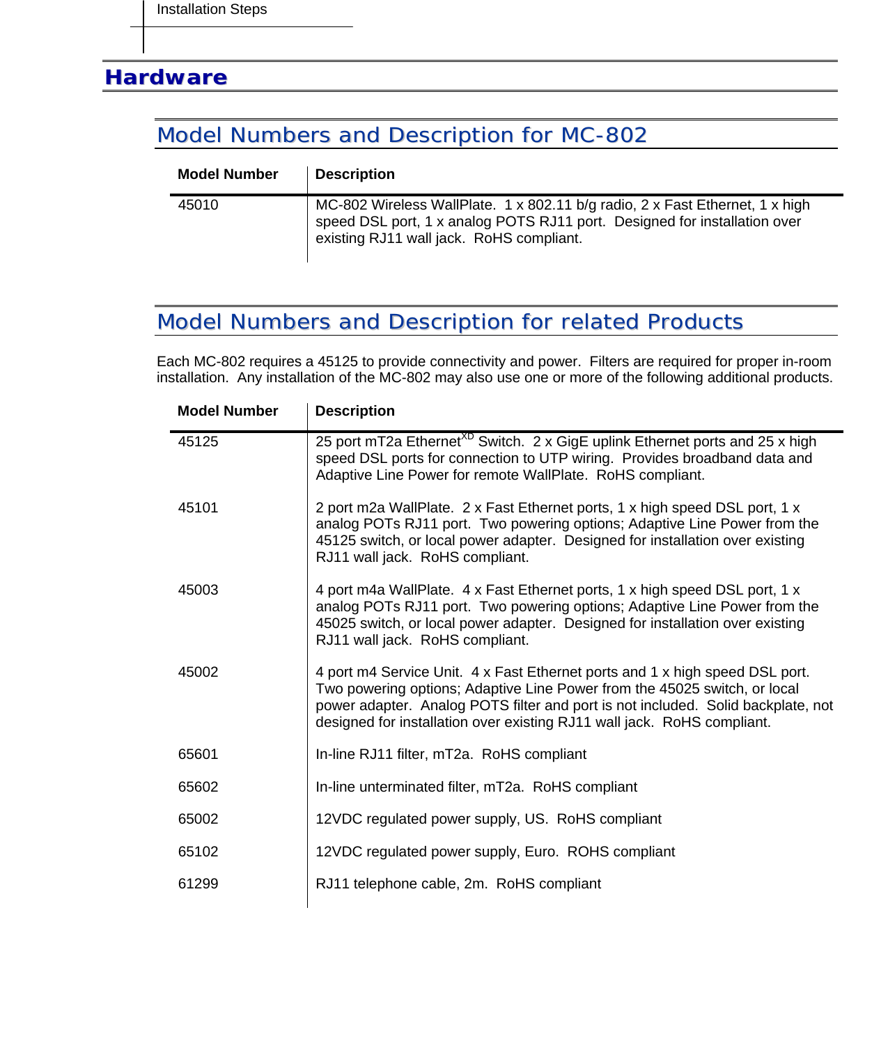
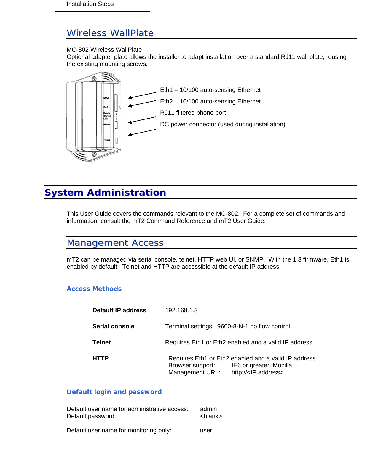
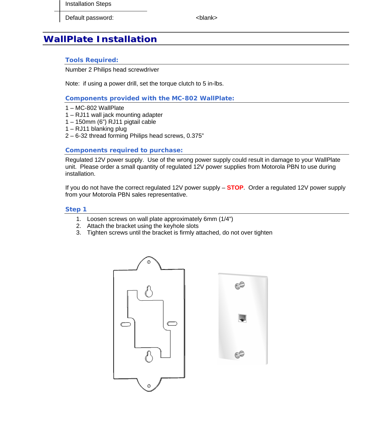
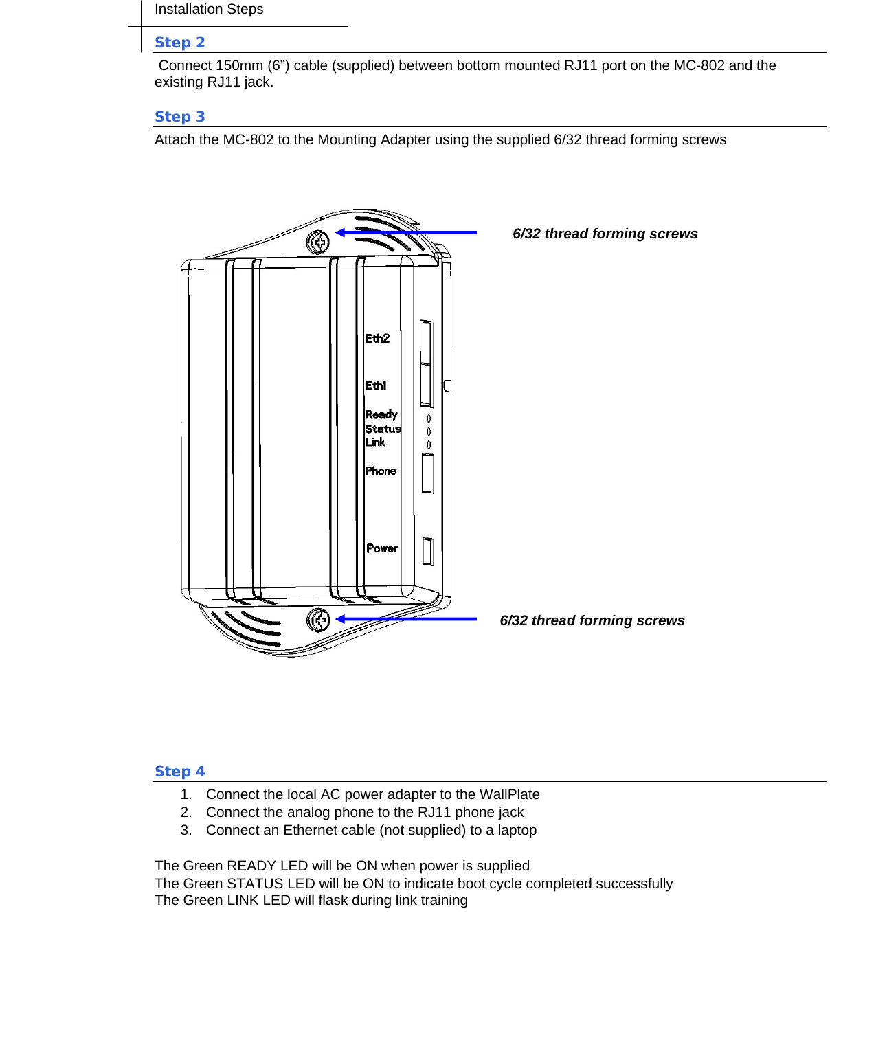
![Installation Steps CCoommmmaanndd RReeffeerreennccee interface wireless config <radio<1-25>(interface-id)> [channel auto|1|2|3|4|5|6|7|8|9|10|11|12|13|14] interface wireless enable <radio<1-25>(interface-id)> interface wireless disable <radio<1-25>(interface-id)> wlan config <wlan<1-25>-1(interface-id)> [ssid string] [security none|wep|wpa-personal] [pre-shared-key string] [wep-key-type 64bit|128bit] length (64 or 128 bits) [wep-key string] wlan enable <wlan<1-25>-1(interface-id)> wlan disable <wlan<1-25>-1(interface-id)> show interface wireless config <radio<1-25>(interface-id)> show interface wireless statistics <radio<1-25>(interface-id)> show wlan config <wlan<1-25>-1(interface-id)> show wlan statistics <wlan<1-25>-1(interface-id)>](https://usermanual.wiki/ARRIS/45010/User-Guide-1060128-Page-13.png)