User Guide

USER GUIDE
MC-802 Wireless WallPlate

No part of this publication may be reproduced or transmitted, in any form or by any means, electronic,
mechanical, photocopying, recording, or otherwise, without the prior written consent of the publisher.
Information in this manual is furnished under license and may only be used in accordance with the terms
of the software license. This publication and the information herein is furnished AS IS, is subject to
change without notice, and should not be construed as a commitment by Motorola. Motorola assumes no
responsibility or liability for any errors or inaccuracies, makes no warranty of any kind (expressed, implied,
or staory) with respect to this publication, and expressly disclaims any and all warranties of
merchantability, fitness for particular purposes, and noninfringement of third-party rights.
Companies, names, and data used in the examples herein are fictitious unless otherwise noted.
Pass-Through Licenses:
Net-SNMP Copyright 1989, 1991, 1992, 1996, 1998-2004
LwIP Copyright © 2001, 2002 Swedish Instie of Computer Science
Net-SNMP and LwIP source code are provided under the terms of their respective license agreements.
Source code and copyright notices are available at http://motorolaonline.com
Copyright © 2005-2006 Motorola, Inc. All rights reserved.
‘Motorola‘ is a registered trademark of Motorola, Inc. in the United States and in other countries.
Other trade names used in this document are trademarks or registered trademarks of the manufacturers
or vendors of the associated products.
Motorola, Inc.
5200 Franklin drive, Suite 100
Pleasanton, CA 94588
1 (925) 201-4500 main
1 (925) 201-4509 fax
1 (800) 998-4888
www.systems.com
Published in the United States of America
August, 2007
MC-802 Wireless WallPlate User Guide
Text part number:
FCC Part 15A
This device complies with part 15 of the FCC Rules. Operation is subject to two conditions:
(1) This device may not cause harmful interference, and (2) this device must accept any interference
received, including interference that may cause undesired operation.
IMPORTANT SAFETY INSTRUCTIONS
MC-802
CAUTION: Use only power supplies listed in the user manual
The maximum operating ambient temperature is 40 degrees Celsius.
When using your telephone equipment, basic safety precautions should always be followed to reduce the
risk of fire, electric shock and injury to persons, including the following:
1. Do not use this product near water, for example, near a bath tub, wash bowl, kitchen sink or laundry
tub, in a wet basement or near a swimming pool.
2. Avoid using a telephone (other than a cordless type) during an electrical storm. There may be a remote
risk of electric shock from lightning.
3. Do not use the telephone to report a gas leak in the vicinity of the leak.
SAVE THESE INSTRUCTIONS
Caring for the Environment by Recycling
When you see this symbol on a Motorola product, do not dispose of the product with residential or
commercial waste.
Recycling your Motorola Equipment
Please do not dispose of this product with your residential or commercial waste. Some
countries or regions, such as the European Union, have set up systems to collect and
recycle electrical and electronic waste items. Contact your local authorities for information
about practices established in your region. If collection systems are not available, contact
Motorola Customer Service for assistance.
WEEE Directive
Motorola is committed to meeting the requirements of the European Union’s Waste Electrical and
Electronic Equipment (WEEE) Directive. This Directive requires producers of electrical and electronic
equipment to finance the take-back for re-use or recycling, of their products placed on the EU market
after 13 August 2005.
Motorola’ products that are within the scope of the Directive are labeled with a crossed-out "wheelie-bin"
symbol as required by the Directive. This indicates that the product was placed on the market after 13
August 2005 and that end-users should segregate the product from other wastes at end-of-life.
Legislation in conformance with the European Commission 2002/96/EC (WEEE) directive can vary from
one member state to the next. Provisions in force in one state do not render another state’s legislation
invalid or convey further requirements than proscribed in the individual state’s legislation.
Product Take-Back and Recycle
Legislative and environmental factors combined with the competitive drive to implement the latest
technology present many companies with the challenge of managing technology surpluses. Motorola
offers customers the Motorola WEEE RMA program to properly dispose of surplus products that have
reached their end of useful life.
Equipment that is returned to Motorola through this program is disposed of in an environmentally safe
manner using processes that comply with the WEEE (EU Directive on Waste Electrical and Electronic
Equipment) regulations, all EPA guidelines, and U.S. environmental laws at all levels of government.
Motorola’ branded products covered by the WEEE RMA program are labeled with a cross-out “wheelie-
bin” symbol as required by the Directive.
WEEE RMA Program
The MC-802 Wireless WallPlate is covered by the WEEE RMA program and subject to the requirements
of the B2B (business to business) provisions of the WEEE legislation in each EC member state. A copy
of the WEEE RMA form can be obtained by emailing support@sys.com.
RoHS Directive
The MC-802 Wireless WallPlate sold to the European Union after July 1, 2006 meet requirements of the
European Union’s Restriction of Hazardous Substances (RoHS) Directive. RoHS restricts the use of
lead, mercury, cadmium, hexavalent chromium and two bromine-containing flame retardants: PBB
(polybrominated biphenyls) and PBDE (polybrominated diphenyl ethers) in electrical and electronic

products placed on the European Market on and after July 1, 2006. Exemptions allow the continued use
of lead in networking infrastructure equipment and a few select components.
Motorola is working closely with its supply chain to assure compliance of all product and materials
provided by our suppliers and partners.

Commands and Syntax 6
Command Hierarchy.................................................................................. 6
Administrative Commands.......................................................................... 6
Hardware 8
Model Numbers and Description for MC-802.................................................. 8
Model Numbers and Description for related Products ...................................... 8
Wireless WallPlate..................................................................................... 9
System Administration 9
Management Access .................................................................................. 9
WallPlate Installation 10
Enable line power.................................................................................... 12
Finish the installation............................................................................... 12
Command Reference 13
Appendix A: Pin-out Assignments 14
Appendix B: Hardware Specifications 15

Commands and Syntax
C
Co
om
mm
ma
an
nd
ds
s
a
an
nd
d
S
Sy
yn
nt
ta
ax
x
The Motorola MC-802 is managed via the Command Line Interface, webUI, and SNMP from a connected
Motorola mT2a EthernetXD Switch. All commands referenced are executed on the mT2a.
C
Co
om
mm
ma
an
nd
d
H
Hi
ie
er
ra
ar
rc
ch
hy
y
The Command Line Interface (CLI) implements a hierarchical command structure. Commands are
organized as a high-level command keyword related to a particular function of the device with sub-
commands related to sub-functions.
You may move down in the command hierarchy by entering root keywords and sub-keywords followed by
the enter key. Your current level in the command hierarchy is referred to as the “command context.” The
top-level context is referred to as the “root command context.” You may move up to the previous
command context by using the exit command. The command prompt displays the current command
context.
Full commands may be entered at the root command context. For example:
system> interface dsl enable port1
You may also move down levels in the command hierarchy, which allows you to execute commands with
less repetitive typing.
For example:
system> interface
system:interface> dsl
system:interface.dsl> enable port1
system:interface.dsl> enable port2
system:interface.dsl> enable port3
system:interface.dsl> exit
system:interface> exit
system>
A
Ad
dm
mi
in
ni
is
st
tr
ra
at
ti
iv
ve
e
C
Co
om
mm
ma
an
nd
ds
s
Most commands discussed in this guide are administrative commands, which change the configuration of
the system or affect the operation of the system. These commands can only be executed from the admin
account. Configuration changes take affect immediately and are recorded in non-volatile memory
(NVRAM) in the default mode. Alternatively, you may choose not to record changes in NVRAM. In this
case, changes will need to be committed before rebooting the system; otherwise the configuration will
revert to the last saved configuration. If automatic commit is enabled, or the configuration is manually
committed, the running configuration will automatically be restored if the system power cycles or is
rebooted.
Show Commands
The show commands are used to view configurations, status and/or statistics. These commands can be
issued from either the user or admin account.
Commands and Syntax
Global Commands
Commands that are available from any command context are called global commands. For example, the
help command can be used whether you are at the root command context or down a few levels in the
command hierarchy. Global commands can also be used from either the user or admin account.
Note: The default prompt is “system>”. If you set the system name using the “system name”
command, the prompt changes to the new system name.
Command Description
clear Clears the screen
exit Use this command to switch to the previous context. Note that using the exit
command at the root command contgext performs the same function as logout.
help Displays the help files
history Shows the history of the commands used in the current session.
logout Can be used with either the login (admin, user, RADIUS network authenticated) and
at any command level to terminate the current session
tree Shows the structure of the command tree
Command Completion
The OS allows you to shorten commands as long as the characters are not ambiguous. While typing a
command, press the tab key to have the system complete the current command word or type (?) to have
the system display a list of available options. The options displayed vary according to the context:
• If you type a ? at a prompt, the system displays a list of all available commands.
• If you type an unambiguous command word, pressing ? displays all available subcommands or
arguments. For example, show ? (note the space before the question mark) displays a list of all show
subcommands.
Style Conventions
The style conventions used in this manual distinguish various elements of the commands and facilitate
the proper interpretation of command syntax, parameters, and their use.
This document refers to actual command syntax as little as possible. For a complete command syntax
document, please refer to the Command Reference guide for a complete list of all available commands,
the proper syntax, and usage examples. In no way does this User Guide attempt to replace or obsolete
the Command Reference.
Interface Range
Multiple interfaces can be specified for a single command using port ranges. Use of hyphens (-) and
commas (,) to delineate ports. Port numbers must be contained in parenthesis. Hyphens and commas
can be combined in the same expression to specify multiple, non-sequential interfaces. For example;
To enable all 25 DSL ports, type: interface dsl enable port(1-25)
To enable only selected DSL ports, type: interface dsl enable port(1,3,5,20-25)
Hyphens and commas can also be used to enable remote Ethernet ports along with DSL ports. For
example;
To enable Eth1 and Eth2 on every WallPlate, type: interface remote enable port(1-25)-(1,2)
VLAN commands can also be completed using interface ranges.
To add VLAN 100 to Eth1 on every WallPlate, type: vlan membership add 100 interface port(1-25)-1

Installation Steps
H
Ha
ar
rd
dw
wa
ar
re
e
M
Mo
od
de
el
l
N
Nu
um
mb
be
er
rs
s
a
an
nd
d
D
De
es
sc
cr
ri
ip
pt
ti
io
on
n
f
fo
or
r
M
MC
C-
-8
80
02
2
Model Number Description
45010 MC-802 Wireless WallPlate. 1 x 802.11 b/g radio, 2 x Fast Ethernet, 1 x high
speed DSL port, 1 x analog POTS RJ11 port. Designed for installation over
existing RJ11 wall jack. RoHS compliant.
M
Mo
od
de
el
l
N
Nu
um
mb
be
er
rs
s
a
an
nd
d
D
De
es
sc
cr
ri
ip
pt
ti
io
on
n
f
fo
or
r
r
re
el
la
at
te
ed
d
P
Pr
ro
od
du
uc
ct
ts
s
Each MC-802 requires a 45125 to provide connectivity and power. Filters are required for proper in-room
installation. Any installation of the MC-802 may also use one or more of the following additional products.
Model Number Description
45125 25 port mT2a EthernetXD Switch. 2 x GigE uplink Ethernet ports and 25 x high
speed DSL ports for connection to UTP wiring. Provides broadband data and
Adaptive Line Power for remote WallPlate. RoHS compliant.
45101 2 port m2a WallPlate. 2 x Fast Ethernet ports, 1 x high speed DSL port, 1 x
analog POTs RJ11 port. Two powering options; Adaptive Line Power from the
45125 switch, or local power adapter. Designed for installation over existing
RJ11 wall jack. RoHS compliant.
45003 4 port m4a WallPlate. 4 x Fast Ethernet ports, 1 x high speed DSL port, 1 x
analog POTs RJ11 port. Two powering options; Adaptive Line Power from the
45025 switch, or local power adapter. Designed for installation over existing
RJ11 wall jack. RoHS compliant.
45002 4 port m4 Service Unit. 4 x Fast Ethernet ports and 1 x high speed DSL port.
Two powering options; Adaptive Line Power from the 45025 switch, or local
power adapter. Analog POTS filter and port is not included. Solid backplate, not
designed for installation over existing RJ11 wall jack. RoHS compliant.
65601 In-line RJ11 filter, mT2a. RoHS compliant
65602 In-line unterminated filter, mT2a. RoHS compliant
65002 12VDC regulated power supply, US. RoHS compliant
65102 12VDC regulated power supply, Euro. ROHS compliant
61299 RJ11 telephone cable, 2m. RoHS compliant
Installation Steps
W
Wi
ir
re
el
le
es
ss
s
W
Wa
al
ll
lP
Pl
la
at
te
e
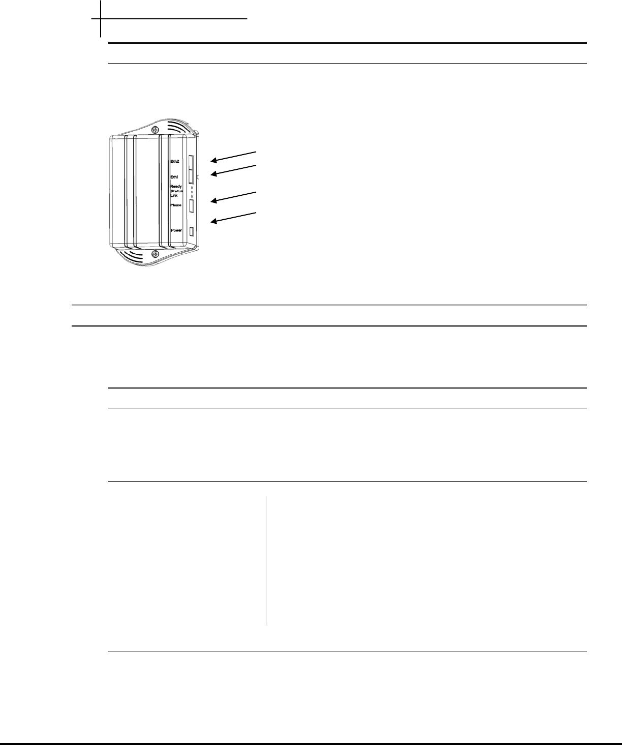
MC-802 Wireless WallPlate
Optional adapter plate allows the installer to adapt installation over a standard RJ11 wall plate, reusing
the existing mounting screws.
S
Sy
ys
st
te
em
m
A
Ad
dm
mi
in
ni
is
st
tr
ra
at
ti
io
on
n
This User Guide covers the commands relevant to the MC-802. For a complete set of commands and
information; consult the mT2 Command Reference and mT2 User Guide.
M
Ma
an
na
ag
ge
em
me
en
nt
t
A
Ac
cc
ce
es
ss
s
mT2 can be managed via serial console, telnet, HTTP web UI, or SNMP. With the 1.3 firmware, Eth1 is
enabled by default. Telnet and HTTP are accessible at the default IP address.
Access Methods
Default IP address 192.168.1.3
Serial console Terminal settings: 9600-8-N-1 no flow control
Telnet Requires Eth1 or Eth2 enabled and a valid IP address
HTTP Requires Eth1 or Eth2 enabled and a valid IP address
Browser support: IE6 or greater, Mozilla
Management URL: http://<IP address>
Default login and password
Default user name for administrative access: admin
Default password: <blank>
Default user name for monitoring only: user
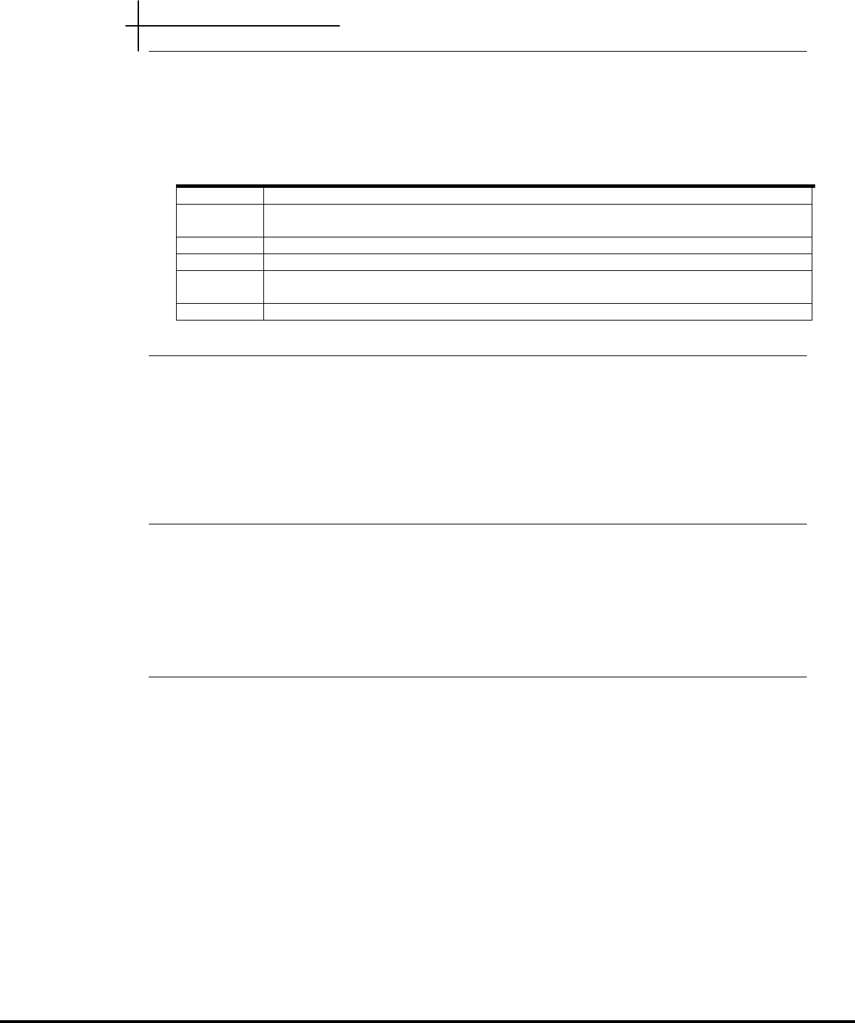
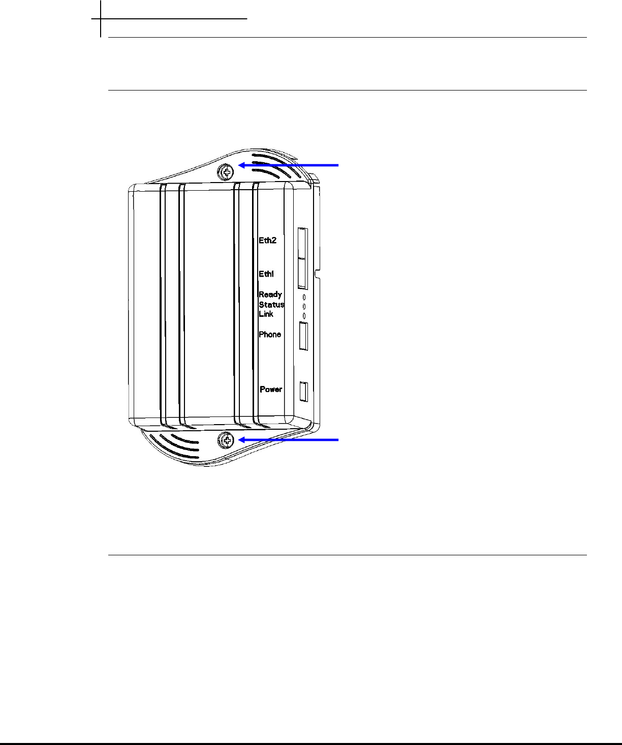
Eth1 – 10/100 auto-sensing Ethernet
Eth2 – 10/100 auto-sensing Ethernet
RJ11 filtered phone port
DC power connector (used during installation)
Installation Steps
Default password: <blank>
W
Wa
al
ll
lP
Pl
la
at
te
e
I
In
ns
st
ta
al
ll
la
at
ti
io
on
n
Tools Required:
Number 2 Philips head screwdriver
Note: if using a power drill, set the torque clutch to 5 in-lbs.
Components provided with the MC-802 WallPlate:
1 – MC-802 WallPlate
1 – RJ11 wall jack mounting adapter
1 – 150mm (6”) RJ11 pigtail cable
1 – RJ11 blanking plug
2 – 6-32 thread forming Philips head screws, 0.375”
Components required to purchase:
Regulated 12V power supply. Use of the wrong power supply could result in damage to your WallPlate
unit. Please order a small quantity of regulated 12V power supplies from Motorola PBN to use during
installation.
If you do not have the correct regulated 12V power supply – STOP. Order a regulated 12V power supply
from your Motorola PBN sales representative.
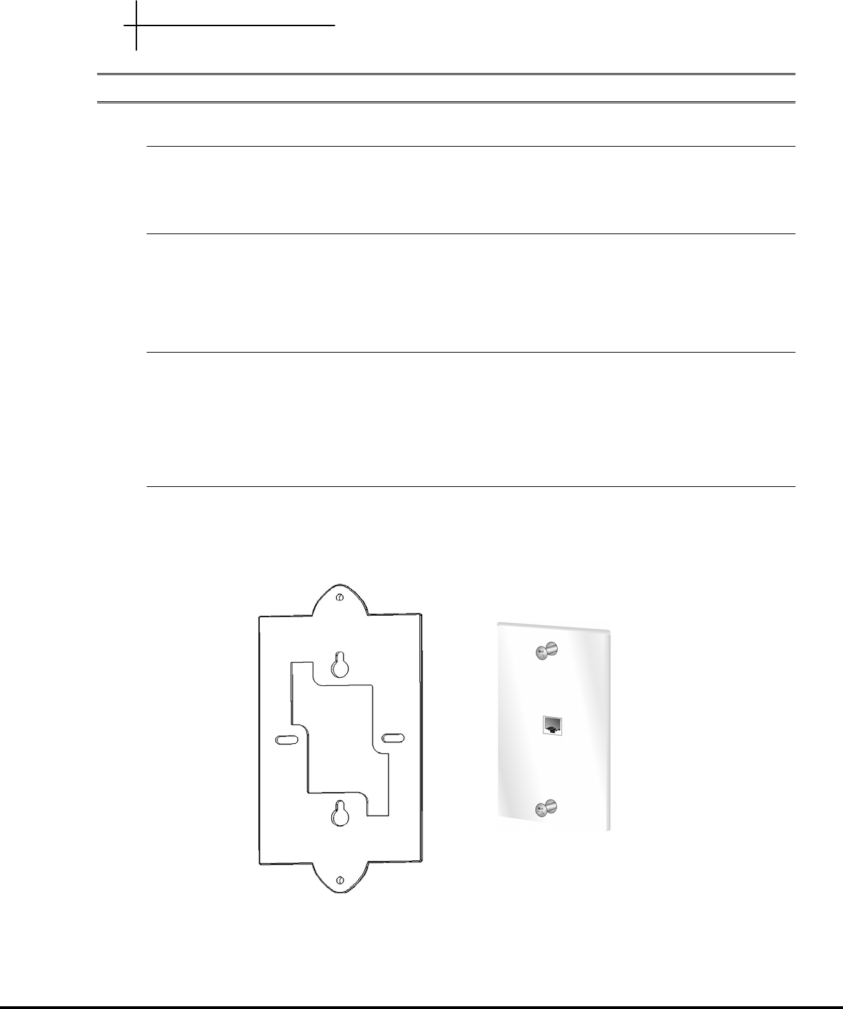
Step 1
1. Loosen screws on wall plate approximately 6mm (1/4”)
2. Attach the bracket using the keyhole slots
3. Tighten screws until the bracket is firmly attached, do not over tighten
Installation Steps
Step 2
Connect 150mm (6”) cable (supplied) between bottom mounted RJ11 port on the MC-802 and the
existing RJ11 jack.
Step 3
Attach the MC-802 to the Mounting Adapter using the supplied 6/32 thread forming screws
Step 4
1. Connect the local AC power adapter to the WallPlate
2. Connect the analog phone to the RJ11 phone jack
3. Connect an Ethernet cable (not supplied) to a laptop
The Green READY LED will be ON when power is supplied
The Green STATUS LED will be ON to indicate boot cycle completed successfully
The Green LINK LED will flask during link training
6/32 thread forming screws
6/32 thread forming screws

Installation Steps
Step 5
After WallPlate Link LED is solid, verify the device is connected using the command, “show int dsl status”
E
En
na
ab
bl
le
e
l
li
in
ne
e
p
po
ow
we
er
r
Login to the mT2 switch using the web UI and HTTP or telnet.
Determine which port is being installed
From the telnet CLI, enter this command:
show bridge address
The MAC address of your PC will appear along with the connected line.
Enable line power
From the telnet CLI, enter this command:
interface dsl power enable portx (enable only the port being installing)
F
Fi
in
ni
is
sh
h
t
th
he
e
i
in
ns
st
ta
al
ll
la
at
ti
io
on
n
Remove the 12V regulated power supply. If the correct port is enabled for line power, the WallPlate will
reset and operate from in-line power.
After the wired network is installed, enable the WLAN on each unit. Example commands below:
interface wireless enable radio(1-25)
interface wlan config wlan(1-25) ssid Motohotel security none
interface wlan enable wlan(1-25)-1
Test the system by connecting to the Internet service provider or other test equipment.

Installation Steps
C
Co
om
mm
ma
an
nd
d
R
Re
ef
fe
er
re
en
nc
ce
e
interface wireless config <radio<1-25>(interface-id)> [channel auto|1|2|3|4|5|6|7|8|9|10|11|12|13|14]
interface wireless enable <radio<1-25>(interface-id)>
interface wireless disable <radio<1-25>(interface-id)>
wlan config <wlan<1-25>-1(interface-id)> [ssid string] [security none|wep|wpa-personal] [pre-shared-key
string] [wep-key-type 64bit|128bit] length (64 or 128 bits) [wep-key string]
wlan enable <wlan<1-25>-1(interface-id)>
wlan disable <wlan<1-25>-1(interface-id)>
show interface wireless config <radio<1-25>(interface-id)>
show interface wireless statistics <radio<1-25>(interface-id)>
show wlan config <wlan<1-25>-1(interface-id)>
show wlan statistics <wlan<1-25>-1(interface-id)>
Appendix A
A
Ap
pp
pe
en
nd
di
ix
x
A
A:
:
P
Pi
in
n-
-o
ou
ut
t
A
As
ss
si
ig
gn
nm
me
en
nt
ts
s
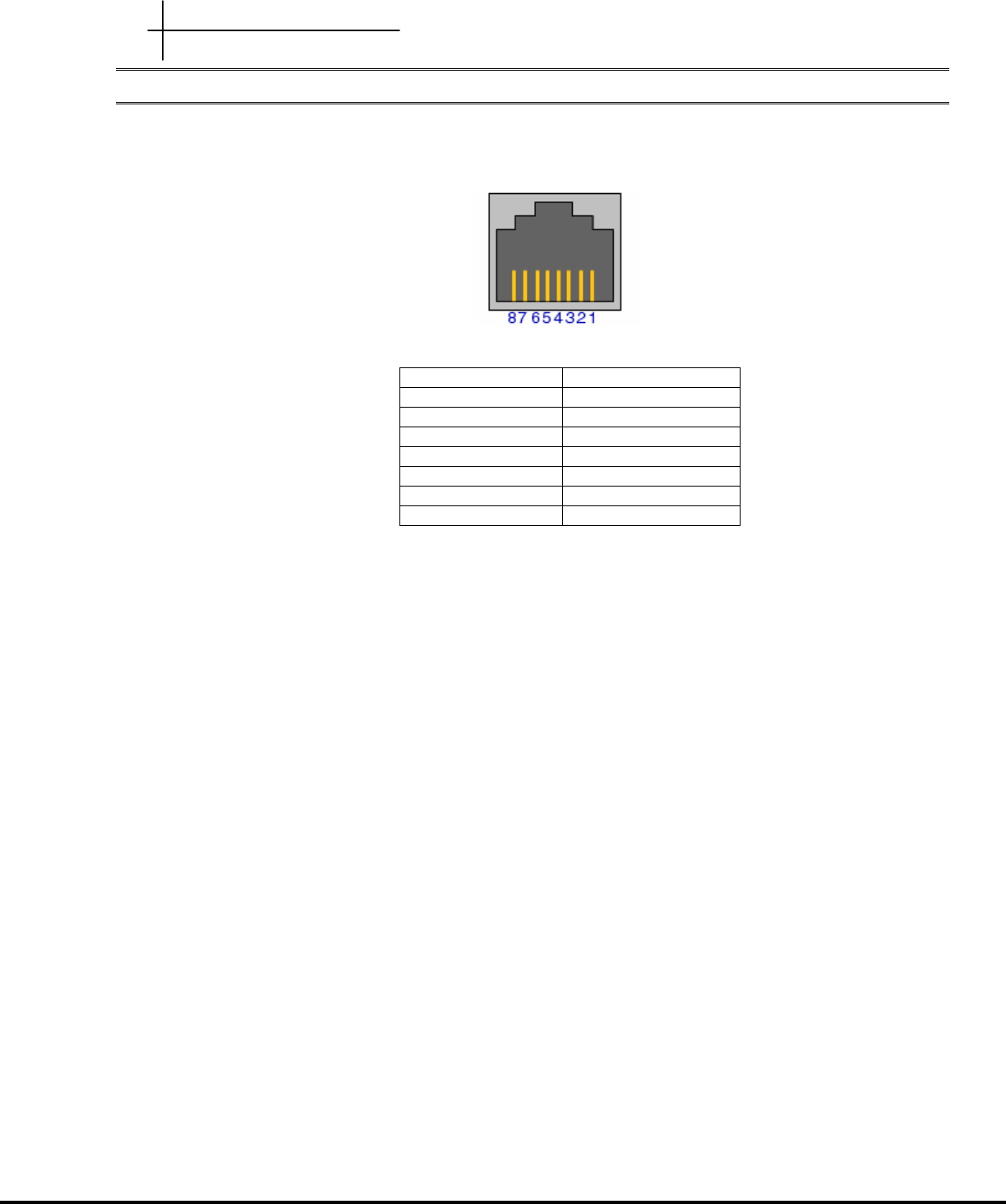
Fast Ethernet WallPlate ports
1 TX+
2 TX-
3 RX+
4 Unused
5 Unused
6 RX-
7 Unused
8 Unused

Appendix C
A
Ap
pp
pe
en
nd
di
ix
x
B
B:
:
H
Ha
ar
rd
dw
wa
ar
re
e
S
Sp
pe
ec
ci
if
fi
ic
ca
at
ti
io
on
ns
s
MC-802 Wireless WallPlate
Interfaces 2 x RJ45, 10/100/Mbps auto-sensing – 328ft (100m)
1 x RJ11, line-in port
1 x RJ11, filtered phone port
Input Voltage Local power supply, 12VDC (not shipped)
Power Consumption 6 watts
Dimensions 3.75” x 6.75” x 1.75”
Weight 11 oz
Environmental Operating Temperature: 0 – 40 degrees Celsius
Relative Humidity 5% to 90% NC
Compliance FCC Part 15A, CISPR 22
FCC Part 15C 15.247
ETSI ETS 300 328 2.4Ghz
EN 55022 : 1994/A1 : 1995/A2 : Class A
EN 55024 : 1998 : Class A
CE, TUV EN60950
RoHS 2002/95/EC
Telephone splitter Integrated analog POTS splitter
Management In Band Management
Telnet, Web UI, SNMP v2 standard and enterprise MIB
Front Panel LEDs 1 x Ready, power status
1 x Status, software booted, errors
1 x Link, xDSL link training
10/100 link status, activity
Mounting Options RJ11 wall plate mounting adapter provided