ARRIS 5200AC Wireless 802.11 uDSL Residential Gateway User Manual user guide 5268
Pace Americas Wireless 802.11 uDSL Residential Gateway user guide 5268
ARRIS >
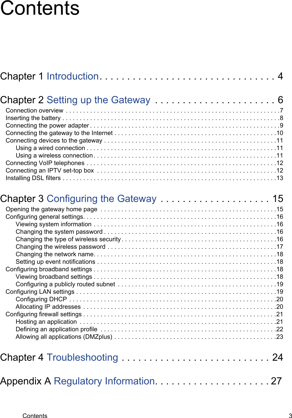
Contents
- 1. User Manual
- 2. RF warnings Insert
- 3. Warning statements insert
User Manual


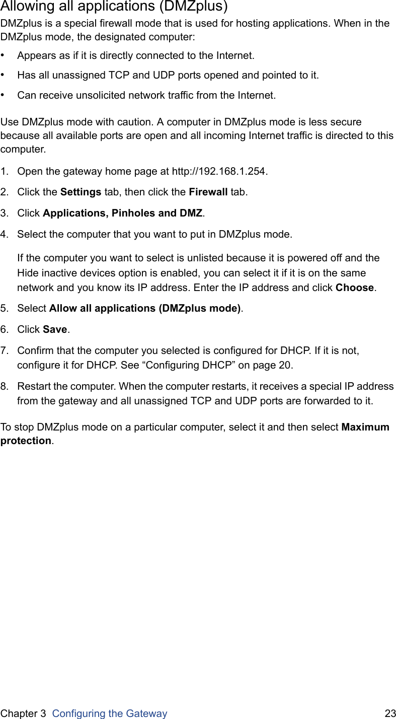
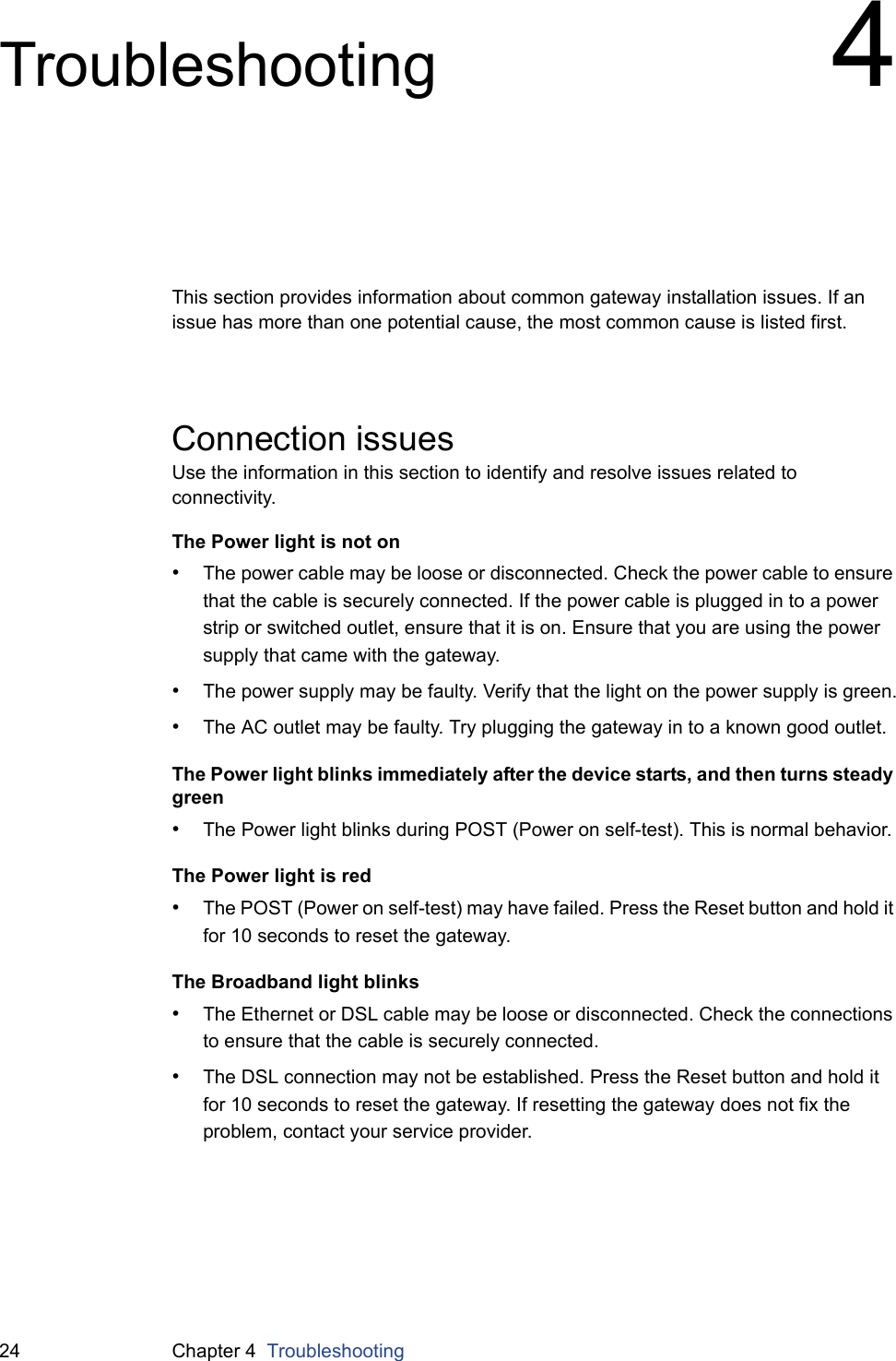
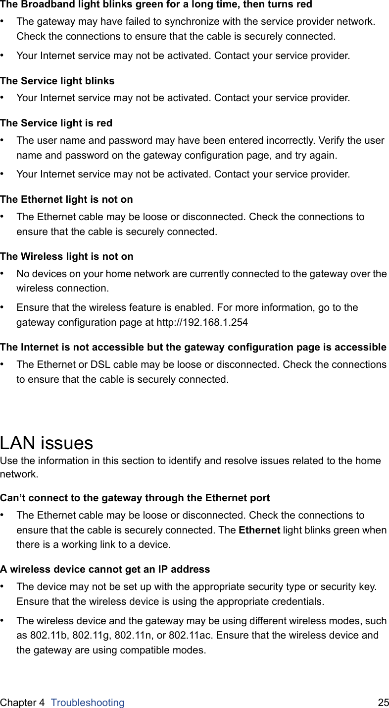
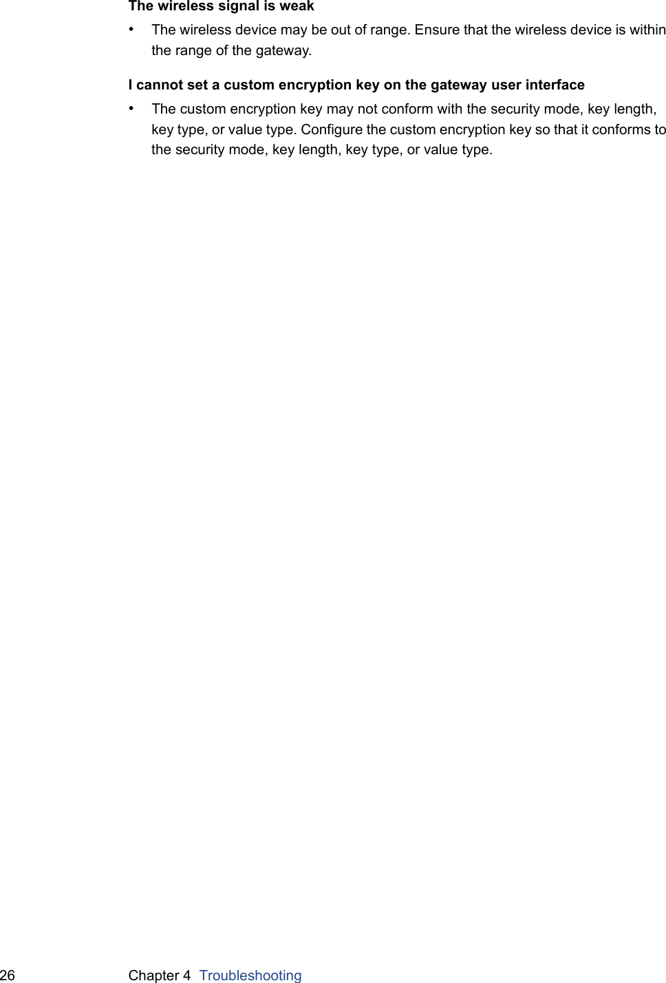
![Chapter 3 Configuring the Gateway 214. Go to the appropriate device and select the following options to override the default DHCP settings:•Firewall. Determines whether the gateway firewall is enabled for the device.•Address Assignment. A specific address or address type.•WAN IP Mapping. The address or address pool from which you want to select an IP address.5. Click Save.Configuring firewall settingsThe gateway’s default firewall settings block unwanted access from the Internet. Most users will not need to change the default firewall settings.If necessary, you can modify the firewall settings to allow certain Internet traffic or users through the firewall to devices on your home network.Hosting an applicationTo allow access from the Internet to applications running on computers inside your home network, you need to open firewall pinholes and associate the intended application with a computer connected with your gateway. If you cannot find a listing for your application, you can define an application with the protocol and port information. For more information, see “Defining an application profile” on page 22.1. Open the gateway home page at http://192.168.1.254.2. Click the Settings tab, then click the Firewall tab.3. Click Applications, Pinholes and DMZ.4. Select the computer that will host the application.If the computer you want to select is unlisted because it is powered off and the Hide inactive devices option is enabled, you can select it if it is on the same network and you know its IP address. Enter the IP address and click Choose.5. Select Allow individual application(s). 6. From the Application List panel, select the application you want to host. You can filter the application list by selecting a category.To select multiple applications, hold down the [Shift] or [Ctrl] keys while making your selections. Using the [Shift] key lets you make your selections in a contiguous order while the [Ctrl] key selects the groups in any order.7. Click Add.8. Click Save.](https://usermanual.wiki/ARRIS/5200AC.User-Manual/User-Guide-2257535-Page-21.png)
![Appendix A Regulatory Information 27Regulatory Information ADeclaration of conformityThe following sections describe regulatory compliance by region.FCC/Industry Canada complianceThis device has been tested and certified as compliant with the regulations and guidelines set forth in the Federal Communication commission - FCC part 15, FCC part 68 and Industry Canada - ICES003 and RSS-210 Radio and telecommunication regulatory requirements.Le présent materiel est conforme aux specifications techniques applicables d'Industrie Canada. Cet appareil numérique de la classe [*] est conforme à la norme NMB-003 du Canada.Manufacturer: Pace AmericasModel(s): 5268acPart 15 of FCC rules / IC RSS-210 - RSS GENThis device complies with part 15 of the FCC Rules and Industry Canada license-exempt RSS standard(s). Operation is subject to the following two conditions: (1) this device may not cause harmful interference, and(2) this device must accept any interference received, including interference that may cause undesired operation of the device.Le présent appareil est conforme aux normes CNR d'Industrie Canada applicables aux appareils radio exempts de licence. L'exploitation est autorisée aux deux conditions suivantes:(1) l'appareil ne doit pas produire de brouillage, et(2) l'utilisateur de l'appareil doit accepter tout brouillage radioélectrique subi, même si le brouillage est susceptible d'en compromettre le fonctionnement.Users should be advised that high-power radars are allocated as primary users (i.e. priority users) of the bands 5250-5350 MHz and 5470-5725 MHz and that these radars could cause interference and/or damage to the LE-LAN device.Les utilisateurs doivent être avisés que les radars de haute puissance sont désignés utilisateurs principaux (c.-à-d., qu'ils ont la priorité) pour les bandes 5250-5350 MHz et 5650-5850 MHz et que ces radars peuvent causer du brouillage et/ou des dommages aux dispositifs LAN-EL.](https://usermanual.wiki/ARRIS/5200AC.User-Manual/User-Guide-2257535-Page-27.png)