ARRIS IPW8X4N Wireless STB User Manual D663 Install
Pace Americas Wireless STB D663 Install
UserManual.wiki
>
ARRIS
>
IPW8X4N User Manual
>
User Manual
Contents
1.
User Manual
2.
User Manual Insert
User Manual
Navigation menu
Upload a User Manual
Namespaces
Wiki Guide
HTML
PDF
Info
Views
User Manual
Discussion / Help
Navigation
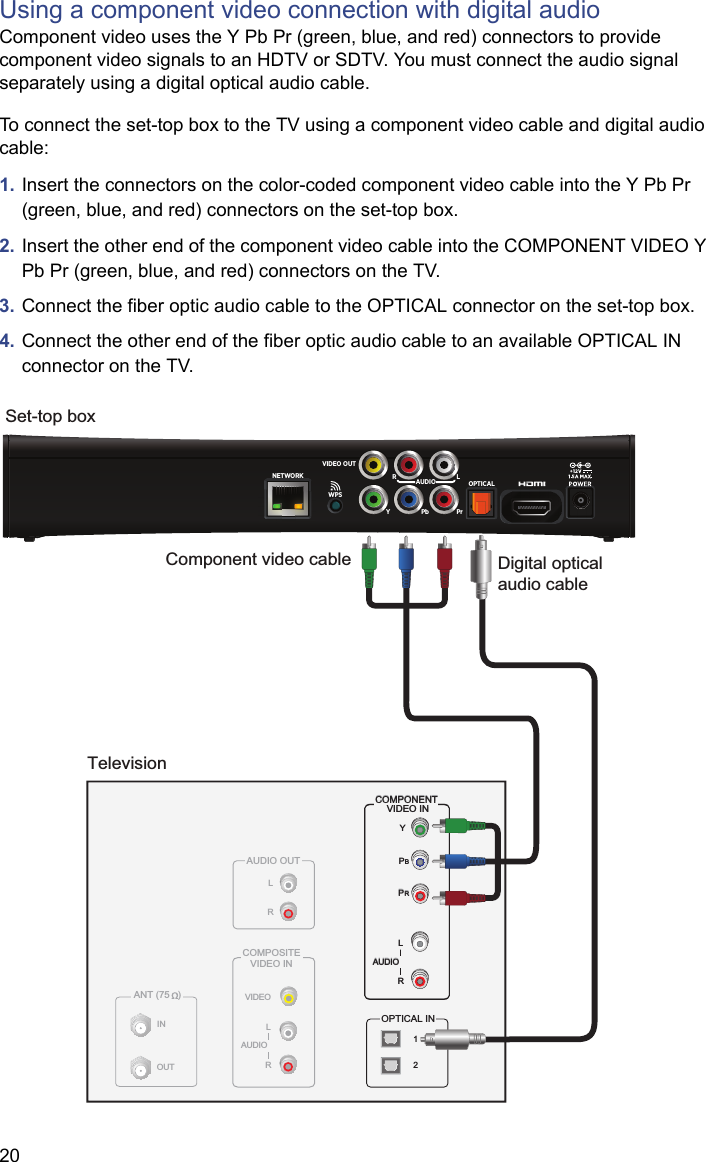
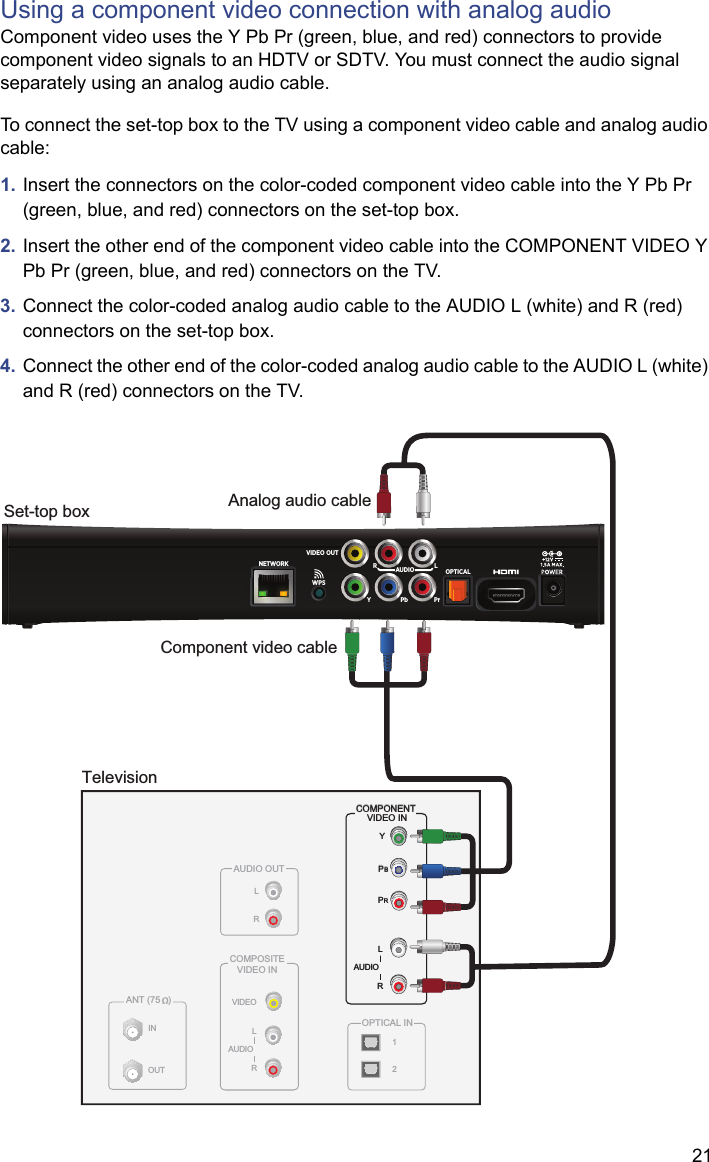
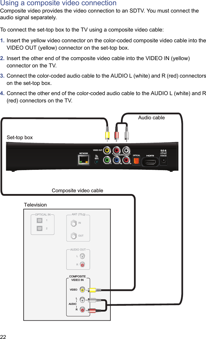
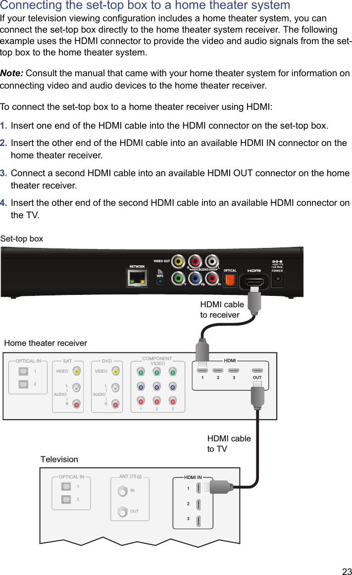
![29Compliance InformationRegulatory informationCAUTION: Do not attempt to modify your set-top box without written authorization from the manufacturer. Unauthorized modification could void your authority to operate your set-top box.Trade Name: Pace AmericasResponsible Party: 2Wire, Inc. DBA Pace AmericasAddress: 1764 Automation Parkway, San Jose, CA 95131Phone: (408) 428-9500Declaration of ConformityFCC / Industry Canada ComplianceThis device has been tested and certified as compliant with the regulations and guidelines set forth in the Federal Communication commission - FCC part 15 and Industry Canada - ICES003 and RSS-210 Radio and telecommunication regulatory requirements / Le présent materiel est conforme aux specifications techniques applicables d'Industrie Canada. Cet appareil numérique de la classe [*] est conforme à la norme NMB-003 du Canada.Manufacturer: 2Wire, Inc. DBA Pace AmericasModel(s): IPW8000Part 15 of FCC Rules / IC RSS-210 – RSS GENThis device complies with part 15 of the FCC Rules and Industry Canada license-exempt RSS standard(s). Operation is subject to the following two conditions: (1) this device may not cause harmful interference, and (2) this device must accept any interference received, including interference that may cause undesired operation of the device.Le présent appareil est conforme aux normes CNR d'Industrie Canada applicables aux appareils radio exempts de licence. L'exploitation est autorisée aux deux conditions suivantes:(1) l'appareil ne doit pas produire de brouillage, et (2) l'utilisateur de l'appareil doit accepter tout brouillage radioélectrique subi, même si le brouillage est susceptible d'en compromettre le fonctionnement.This equipment has been tested and found to comply with the limits for a Class B digital device, pursuant to Part 15 of the FCC Rules. These limits are designed to provide reasonable protection against harmful interference in a residential installation. This equipment generates, uses, and can radiate radio-frequency energy and, if not installed and used in accordance with the instructions, may cause harmful interference to radio communications. However, there is no guarantee that interference will not occur in a particular installation. If this equipment does cause harmful interference to radio or television reception, which can be determined by turning the equipment off and on, you are encouraged to try to correct the interference by one or more of the following measures:•Reorient or relocate the receiving antenna.•Increase the separation between the equipment and the receiver.•Connect the equipment to an outlet on a circuit that is different from the circuit used by the receiver.•Consult your dealer or an experienced radio/TV technician for help.](https://usermanual.wiki/ARRIS/IPW8X4N.User-Manual/User-Guide-2102650-Page-29.png)