Contents
- 1. User Manual
- 2. User Manual Insert
User Manual
BRINGING TECHNOLOGY HOME
www.pace.com
INSTALLATION GUIDE
HD IPTV Set-Top Box
IPW8000
3
Contents
Safety Information . . . . . . . . . . . . . . . . . . . . . . . . . . . . . . . 4
Warnings on the power supply unit . . . . . . . . . . . . . . . . . . . . . . . . . . . . . . . . . . . . . 4
Other warnings . . . . . . . . . . . . . . . . . . . . . . . . . . . . . . . . . . . . . . . . . . . . . . . . . . . . . 4
Important safety instructions . . . . . . . . . . . . . . . . . . . . . . . . . . . . . . . . . . . . . . . . . . 5
Safety aspects of connections . . . . . . . . . . . . . . . . . . . . . . . . . . . . . . . . . . . . . . . . . 7
Note to the installer . . . . . . . . . . . . . . . . . . . . . . . . . . . . . . . . . . . . . . . . . . . . . . . . . 8
Introduction . . . . . . . . . . . . . . . . . . . . . . . . . . . . . . . . . . . . 9
Package contents. . . . . . . . . . . . . . . . . . . . . . . . . . . . . . . . . . . . . . . . . . . . . . . . . . . 9
Model number and serial number. . . . . . . . . . . . . . . . . . . . . . . . . . . . . . . . . . . . . . 10
Front panel . . . . . . . . . . . . . . . . . . . . . . . . . . . . . . . . . . . . . . . . . . . . . . . . . . . . . . . 11
Back panel . . . . . . . . . . . . . . . . . . . . . . . . . . . . . . . . . . . . . . . . . . . . . . . . . . . . . . . 12
Connecting the Set-Top Box . . . . . . . . . . . . . . . . . . . . . . 13
Connect the set-top box to the home network . . . . . . . . . . . . . . . . . . . . . . . . . . . . 14
Connect the set-top box to the TV . . . . . . . . . . . . . . . . . . . . . . . . . . . . . . . . . . . . . 15
Determining the type of connection to use. . . . . . . . . . . . . . . . . . . . . . . . . . . . . 15
Using an HDMI connection . . . . . . . . . . . . . . . . . . . . . . . . . . . . . . . . . . . . . . . . 17
Using a DVI connection with digital audio . . . . . . . . . . . . . . . . . . . . . . . . . . . . . 18
Using a DVI connection with analog audio . . . . . . . . . . . . . . . . . . . . . . . . . . . . 19
Using a component video connection with digital audio . . . . . . . . . . . . . . . . . . 20
Using a component video connection with analog audio . . . . . . . . . . . . . . . . . . 21
Using a composite video connection . . . . . . . . . . . . . . . . . . . . . . . . . . . . . . . . . 22
Connecting the set-top box to a home theater system . . . . . . . . . . . . . . . . . . . 23
Plug in the set-top box . . . . . . . . . . . . . . . . . . . . . . . . . . . . . . . . . . . . . . . . . . . . . . 24
Connecting to the AC power supply. . . . . . . . . . . . . . . . . . . . . . . . . . . . . . . . . . 24
Troubleshooting and Support. . . . . . . . . . . . . . . . . . . . . . 25
Troubleshooting . . . . . . . . . . . . . . . . . . . . . . . . . . . . . . . . . . . . . . . . . . . . . . . . . . . 25
Frequently asked questions . . . . . . . . . . . . . . . . . . . . . . . . . . . . . . . . . . . . . . . . . . 27
Picture formats . . . . . . . . . . . . . . . . . . . . . . . . . . . . . . . . . . . . . . . . . . . . . . . . . . . . 28
Compliance Information . . . . . . . . . . . . . . . . . . . . . . . . . . 29
Regulatory information . . . . . . . . . . . . . . . . . . . . . . . . . . . . . . . . . . . . . . . . . . . . . . 29
Declaration of Conformity . . . . . . . . . . . . . . . . . . . . . . . . . . . . . . . . . . . . . . . . . 29

4
Safety Information
This digital set-top box has been manufactured and tested with your safety in mind.
However, improper use can result in potential electric shock, property damage or fire
hazards. To avoid defeating the safeguards that have been built into your set-top box,
please observe the precautions discussed in this document.
Warnings on the power supply unit
The lightning flash with arrowhead symbol, within a triangle, is intended to
alert you to the presence of uninsulated “dangerous” voltages within your
set-top box’s enclosure that may be of sufficient magnitude to constitute a
risk of electric shock to persons.
The exclamation point within a triangle is intended to alert you to the
presence of important instructions in the literature accompanying your set-
top box.
To ensure correct operation, use this set-top box only with the Pace-approved power
supply unit provided. If you use an unapproved alternative, you will invalidate the
warranty.
Other warnings
•To reduce the risk of electric shock, do not remove the cover of your set-top box.
There are no user-serviceable parts inside it.
•Do not perform any servicing unless you are qualified to do so. Refer all servicing to
qualified service personnel. Servicing the set-top box yourself will invalidate the
warranty.
•To reduce the risk of fire or electric shock, do not expose this set-top box to rain or
moisture.
•On the rear panel of your set-top box there is a tamper-evident label that states
“Warranty void if broken or removed.”
•To avoid possible damage to the apparatus or to a connected TV or component, all
AC power cords must be plugged into properly wired outlets. As with all electrical
products, connection to faulty or defective components, or the failure to connect the
apparatus to a properly wired outlet, may cause sparking, property damage or
damage to any TV or other component connected to the apparatus and pose a fire
hazard.
•Failure to heed the Safety Information provided by failing to connect to a properly
wired outlet may void the manufacturer's warranty.
5
Important safety instructions
Before you install or use the apparatus, you must read and understand these Important
Safety Instructions. At all times when installing or using the apparatus you must follow
these Important Safety Instructions to reduce the risk of fire, electrical shock, property
damage and injury to persons.
1. Read these instructions.
2. Keep these instructions.
3. Heed all warnings.
4. Follow all instructions.
5. Do not use this apparatus near water.
6. Clean only with dry cloth.
7. Do not block any ventilation openings. Install in accordance with the manufacturer’s
instructions.
8. Do not install near any heat sources such as radiators, heat registers, stoves, or
other apparatus (including amplifiers) that produce heat.
9. Protect the power cord from being walked on or pinched, particularly at plugs,
convenience receptacles, and the point where they exit from the apparatus.
10.Only use attachments and accessories specified by the manufacturer.
11. Use only with the cart, stand, tripod, bracket, or table specified by the manufacturer,
or sold with the apparatus. When a cart is used, use caution when moving the cart
or apparatus combination to avoid injury from tip-over.
12.Unplug this apparatus during lightning storms or when unused for long periods of
time.
13.Refer all servicing to qualified service personnel. Servicing is required when the
apparatus is damaged in any way, such as a power-supply cord or plug is
damaged, liquid is spilled or objects have fallen into the apparatus, the apparatus is
exposed to rain or moisture, does not operate normally, or has been dropped.
In addition to the “Important safety instructions” section, please read the safety
information below.
Power sources
The model number, serial number, and electrical rating of this set-top box are on a
label on its base.
You must operate your set-top box only from the type of power source indicated on the
marking label. If you are not sure of the type of power supply to your home, consult
your dealer or local power company. If you move your set-top box between locations at
different temperatures, allow it to reach room temperature before you apply power to it.
6
Overloading
Do not overload wall AC outlets, extension cords, or other power outlets as this can
result in a risk of fire or electric shock.
Lightning
For added protection for your set-top box during a lightning storm, or when it is left
unattended and unused for long periods of time, disconnect your set-top box from the
power supply and disconnect the cable system from your set-top box. See also item 12
in the “Important safety instructions”.
Ambient temperature
The operating temperature range of your set-top box is 32-104° F. If the ambient
temperature around your set-top box falls outside this range, you must correct this in
order for your set-top box to work correctly and safely. For example, if the temperature
is too high, make sure there is sufficient ventilation and that your set-top box is not
directly on top of or underneath other equipment.
Ventilation and location
Slots and openings in the casing of your set-top box are provided for ventilation, to
ensure reliable operation of your set-top box and to protect it from overheating.
•Never block the ventilation openings by placing your set-top box on a bed, sofa, rug,
or other similar surface. Place it on a hard, flat surface.
•Never cover the ventilation openings with items such as newspapers, tablecloths, or
curtains.
•You can place your set-top box near other consumer electronics devices, such as
stereo amplifiers or televisions, but you must not place it directly on top or
underneath them.
•Do not place your set-top box in a built-in installation such as a bookcase or rack
unless proper ventilation is provided and you have adhered to the manufacturer’s
instructions.
•Maintain a minimum distance of three inches around your set-top box for sufficient
ventilation.
See also item 7 in the “Important safety instructions”.
Water and moisture
Do not expose this product to dripping or splashing liquids, rain, or moisture. Objects
filled with liquids, such as vases, should not be placed on the set-top box. See also
item 5 in the “Important safety instructions”.
7
Entry of objects and liquids
Never push objects of any kind into your set-top box through openings as they may
touch dangerous voltage points or short-out parts that could result in fire or electric
shock. Never spill liquid of any kind on your set-top box.
Placement and mounting
Do not place your set-top box on an unstable or uneven surface. Your set-top box may
fall, causing serious injury to a child or adult and serious damage to your set-top box. If
you mount your set-top box, for example to a wall or ceiling, follow the manufacturer’s
instructions and use a mounting accessory recommended by the manufacturer. See
also item 11 in the “Important safety instructions”.
Risk of fire or scorching
Never place open flame sources, such as lighted candles, on or adjacent to your set-
top box.
Replacement parts
When replacement parts are required, be sure that the service technician has used
replacement parts specified by the manufacturer or that have the same characteristics
as the original part. Unauthorized substitutions may result in fire, electric shock, or
other hazards. See also item 13 in the “Important safety instructions”.
Safety check
Upon completion of any service or repairs to this product, the service technician must
perform safety checks to determine that your set-top box is in proper operating
condition. See also item 13 in the “Important safety instructions”.
SAVE THIS INFORMATION FOR FUTURE REFERENCE
Safety aspects of connections
For full details about the rear panel connections, see “Connecting the Set-Top Box” on
page 13.
Connecting
Do not connect your set-top box (or any other equipment such as a TV or VCR) to the
power supply until you have properly connected all the other cables. Your set-top box
is designed for use only with the supplied power supply unit.
On the power supply unit there is a label that specifies the correct AC power supply
input for it. Do not connect the power supply unit to any supply other than this.
Always connect the 12 volt connector from the power supply unit to your set-top box
before you insert the AC power connector from the power supply unit into the wall AC
outlet.
8
Disconnecting
To disconnect power from your set-top box, always detach the power supply unit from
the wall AC outlet (rather than remove the 12 volt connector from your set-top box).
You must install your set-top box near to the wall AC outlet, which should be easily
accessible.
If you are in any doubt about the power supply unit, its plug or its connection, consult a
qualified electrician.
Note to the installer
The servicing instructions in this notice are for use by qualified service personnel only.
To reduce the risk of electric shock, do not perform any servicing other than that
contained in the operating instructions, unless you are qualified to do so. To reduce the
risk of electric shock, do not remove the cover or back. There are no user-serviceable
parts inside the unit. Refer all servicing issues to qualified service personnel.
Service address:
Pace Americas, Inc.
3701 FAU Blvd., Suite 200
Boca Raton, FL 33431
9
Introduction
Welcome to Internet Protocol Television (IPTV). The IPW8000 set-top box brings a
new set of interactive services directly to you through your TV and your in-home IP
network. The set-top box uses a wireless network connection or an Ethernet home
network cable to connect to most entertainment devices.
The following IPTV services may be available through this set-top box:
•Digital Video Recorder (DVR). Allows you to record your favorite programs to an
internal hard disk (or an external DVR device) and watch them at your convenience.
•Pause Live TV. Allows you to pause the live broadcast on your TV and come back
to the show where you left it. (Applies to DVR models only.)
•High-Definition (HD). Provides crystal-clear picture and sound when compared to
standard definition.
•Video-On-Demand (VOD). Gives you access to a library of movies and programs
that you can watch, when you want to watch them.
Note: Contact your service provider to find out if the DVR, HD, or VOD services are
available and how to activate the services.
Package contents
In addition to this installation manual, the set-top box carton contains the following
items:
•IPW8000 receiver. A TV set-top box that supports high-definition (HD) and
standard-definition (SD) video decoding. It supports 720p and 1080i content and
uses Ethernet over CAT-5 or wireless Wi-Fi Protected Setup to connect to the in-
home network.
•Power cord and adapter. A 12 volt power supply unit that provides power from an
AC wall outlet to the set-top box.

10
Before using the set-top box, read the “Important safety instructions” on page 5 of this
manual. This manual describes how to connect your set-top box to both your in-home
IP network and your entertainment system. The manual also outlines safeguards and
installation information. The safety information contained in this manual was
developed and provided solely by the set-top box manufacturer, Pace Americas.
Model number and serial number
At times your service provider may ask for your serial number. To find the model
number and serial number for your set-top box, look at the label affixed to the bottom
of the unit. The model number is the first alphanumeric identifier to the right of the
Pace logo. The serial number is the numeric code to the right of the letters “S/N” on the
label, as shown on the following sample label.
Use the space below to record the model number and serial number for your set-top
box:
Model number: _________________________________
Serial number: _________________________________
GUID: xxxxxxxx-xxxxxxxx-xxxx-xxxxxxxxxx
Model: IPW8000
Pace Wireless DEV STB
Basic SD/HD with Wi-Fi
Electrical Rating: 12V 1.5A
HW: A
SW: IPTVL-1015
Factory ID: CCT
Made in Thailand
Manufactured under license from Dolby
Laboratories. Dolby and the double-D symbol
are trademarks of Dolby Laboratories. LISTED
LISTED
I.T.E.
E205389
US
US
C
C
S/N: 1234567890123
Date of Mfg: MM/YYYY
Wi-Fi MAC: 01:02:03:ab:cd:0d
Wireless Network Key: 1234567890
SSID: PACE009
P/N: 123T567890123
FCC ID: PGRIPW8X4N
ICES/NMB-003 B
IC:3439B-IPW8X4N
This device complies with part 15 of the FCC Rules. Operation is subject
to the following two conditions: (1) this device may not cause harmful
interference, and (2) this device must accept any interference
received, including interference that may cause undesired operation.
Serial number
location
Model number
location
11
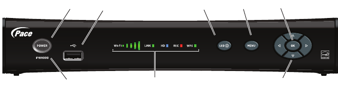
Front panel
The illustration shows the interface elements on the front of the set-top box.
Power button
Turns the set-top box on or off.
Power light
Lights green when the set-top box is powered on. Blinks when receiving input from the
remote control or when the front-panel buttons are pressed.
Model number
Identifies the model number of the set-top box.
USB port
Reserved for future use.
WI-FI light
Lights green to indicate the strength of the Wi-Fi signal. Five bars equals full strength.
LINK light
Lights green when the box has a good connection to the provider network.
HD light
Lights blue to indicate a high-definition input signal.
REC light
Lights red when the DVR is recording content.
WPS light
Blinks green during Wi-Fi Protected Setup pairing with the home network. Lights solid
green for approximately five minutes if device pairing is successful.
LED button
Adjusts the brightness of the LED lights.
MENU button
Launches the on-screen menu.
Arrow buttons
Navigates to on-screen menu options.
OK button
Confirms the on-screen menu choice.
Power button Menu button
Arrow buttons
USB port
Model number Status lights
OK buttonLED button
12
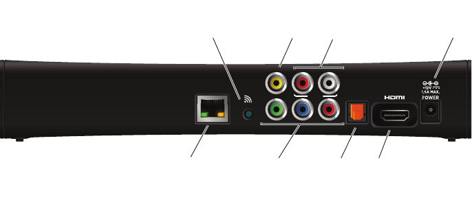
Back panel
The following illustration shows the connectors on the back of the set-top box.
NETWORK
Connects the set-top box to the in-home network using an Ethernet network cable, if
applicable.
WPS
Connects the set-top box to the in-home network using WPS (Wi-Fi Protected Setup),
if a wireless network is available.
VIDEO OUT
Connects the set-top box to a standard-definition TV using a composite video
connection.
Y Pb Pr
Connects the set-top box to a high-definition TV or home theater receiver using a
component video connection.
AUDIO
Connects the set-top box to a TV or home theater receiver using an analog audio
connection.
OPTICAL
Connects the set-top box to a TV or home theater receiver using a digital audio
connection.
HDMI
Connects the set-top box to a high-definition TV or home theater receiver using an
HDMI connection.
POWER
Connects the power adapter to the set-top box. The LED lights green when the set-top
box is receiving power from the wall outlet.
YPbPr
OPTICAL
NETWORK RL
AUDIO
VIDEO OUT
WPS
Wi-Fi Protected
Setup button
Component
video
output
Analog
audio
output
HDMI
output
Network
port
Composite
video
output Power
Digital audio
output
(optical)
13
Connecting the Set-Top Box
To view programs broadcast in high definition, your set-top box must be connected to a
suitable high-definition TV or computer monitor. Your set-top box is also compatible
with standard-definition TVs and VCRs.
Your set-top box should have been connected to your TV by your installer. However, if
you need to disconnect and re-connect your equipment, please read the information in
this chapter carefully before you re-connect the set-top box to your TV or home theater
receiver.
WARNING: Before you begin:
•Do not connect your set-top box (or any other equipment such as a TV or DVD
player) to the AC power supply until you have properly connected all the other
cables.
•Disconnect your set-top box from the AC power supply before you disconnect any
other equipment from its rear panel.
•To disconnect power from your set-top box, always detach the power supply unit
from the wall electrical outlet (rather than removing the cord from your set-top box).
You should install your set-top box near a wall electrical outlet that is easily
accessible.
•Any cable connected to the DIGITAL AUDIO jack must be a fiber optic TOSLINK
connector, not a regular audio cable.
•If you are in any doubt about the power supply cord, its plug or its connection,
consult a qualified electrician.
14
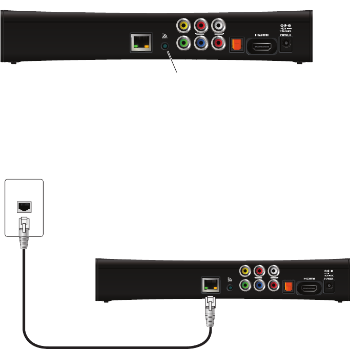
Connect the set-top box to the home network
If you connect to your home network through a wireless connection, use the WPS
(Wi-Fi Protected Setup) connector on the back panel of the set-top box to connect the
set-top box to the network.
To connect to the home network using WPS:
1. Press the WPS button on the back panel of the set-top box. Then, press the WPS
button on the home network gateway.
2. Verify that the WPS indicator on the front panel blinks green during device pairing
with the home network gateway.
3. Verify that the WPS indicator on the front panel lights solid green for approximately
five minutes after the set-top box connects to the gateway.
To connect to the home network using an Ethernet (CAT-5) cable:
1. Insert one end of the Ethernet cable into the NETWORK connector on the set-top
box.
2. Insert the other end of the Ethernet cable into the home network wall outlet.
Note: If an Ethernet connection is made, the wireless interface is disabled.
YPbPr
OPTICAL
NETWORK RL
AUDIO
VIDEO OUT
WPS
Press the WPS button to initiate
pairing with the home network
Set-top box
YPbPr
OPTICAL
NETWORK RL
AUDIO
VIDEO OUT
WPS
Wall outlet
Ethernet cable
Set-top box
15
Connect the set-top box to the TV
The connections for an HD or SD TV are different, and before you begin, you must
determine if your TV is HD or SD. Your TV must receive HD signals for you to enjoy the
benefits of HDTV. Refer to the manual that came with your TV for more information.
Determining the type of connection to use
The connection type you use is determined by the type of connections on your TV or
home theater receiver. The following tables list the connectors that can be used for
high-definition TVs and standard-definition TVs, respectively.
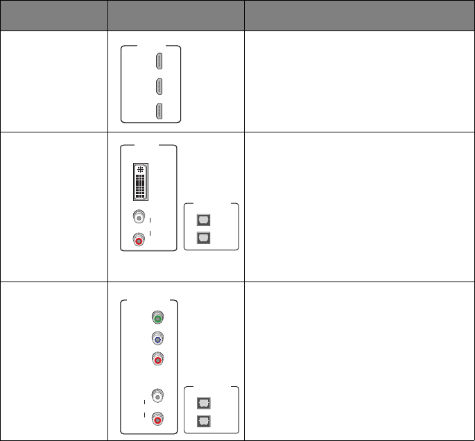
Connections for HDTV
To use the set-top box with high-definition TVs, use one of the following connections to
view HD content. For more information about making HDTV connections, check the
owner’s manual for your TV and the appropriate connection diagrams in this manual.
Note: The labeling on your HDTV may vary slightly from the illustrations shown in the
table.
Name Connector Description
HDMI Provides the HD connection using an
HDMI input on the TV. The HDMI-to-HDMI
connection transmits both HD video and
digital audio. For connection information
using HDMI, see “Using an HDMI
connection” on page 17.
DVI Provides the HD connection using a DVI
input on the TV. The HDMI-to-DVI
connection transmits HD video only. For
digital audio, use a TOSLINK fiber optic
cable to connect to the digital audio
connector on the TV. For standard audio,
use the Audio L/R RCA connectors. For
connection information using DVI, see
“Using a DVI connection with digital audio”
on page 18.
Component video Provides the HD connection using the
component video input on the TV. For
digital audio, use a TOSLINK fiber optic
cable to connect to the digital audio
connector on the TV. For standard audio,
use the Audio L/R RCA connectors. For
connection information using component
video, see “Using a component video
connection with digital audio” on page 20.
HDMI IN
1
2
3
HDMI IN
1
2
3
DVI IN
L
R
AUDIO
L
R
AUDIO
DVI IN
OPTICAL IN
1
2
Y
PB
PR
COMPONENT
VIDEO IN
L
R
AUDIO
Y
PB
PR
L
R
AUDIO
COMPONENT
VIDEO IN
OPTICAL IN
1
2
16
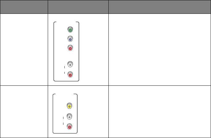
Connections for SDTV
To use the set-top box with standard-definition TVs, you need to use one of the
following connections to view SD content. For more information about making SDTV
connections, check the owner’s manual for your TV and the appropriate connection
diagrams in this manual.
Note: The labeling on your SDTV may vary slightly from the illustrations shown in the
table.
Name Connector Description
Component video Provides the SD connection using the
component video input on the TV. For
standard audio, use the Audio L/R RCA
connectors. For connection information
using component video, see “Using a
component video connection with analog
audio” on page 21.
Composite video Provides the SD connection using the
composite video input on the TV. For
standard audio, use the Audio L/R RCA
connectors. For connection information
using composite video, see “Using a
composite video connection” on page 22.
Y
PB
PR
COMPONENT
VIDEO IN
L
R
AUDIO
Y
PB
PR
L
R
AUDIO
COMPONENT
VIDEO IN
VIDEO
COMPOSITE
VIDEO IN
L
R
AUDIO
VIDEO
COMPOSITE
VIDEO IN
L
R
AUDIO
17
Using an HDMI connection
The HDMI connector provides the connection to an HDTV. HDMI carries signals for
video and audio.
To connect the set-top box to the TV using an HDMI cable:
1. Insert one end of the HDMI cable into the HDMI connector on the set-top box.
2. Insert the other end of the HDMI cable into an available HDMI connector on the TV.
Note: The HDMI port on the TV must support high-bandwidth digital content protection
(HDCP).
Television
HDMI IN
1
2
3
ANT (75 )
IN
OUT
VIDEO
COMPOSITE
VIDEO IN
L
R
AUDIO
DVI IN
L
R
AUDIO
AUDIO OUT
L
R
OPTICAL IN
Y
PB
PR
COMPONENT
VIDEO IN
L
R
AUDIO
1
2
HDMI cable
Set-top box
YPbPr
OPTICAL
NETWORK RL
AUDIO
VIDEO OUT
WPS
HDMI IN
1
2
3
18
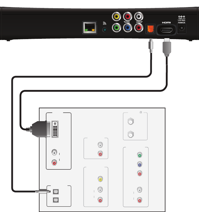
Using a DVI connection with digital audio
The HDMI connector on the set-top box can provide the connection to an HDTV with a
DVI input. If your HDTV has a Digital Visual Interface (DVI) connector, you need an
HDMI-to-DVI cable and a separate digital optical audio cable.
To connect the set-top box to the TV using an HDMI-to-DVI cable and digital audio
cable:
1. Insert the HDMI end of the cable into the HDMI connector on the set-top box.
2. Insert the 24-pin DVI end of the cable into the DVI connector on the TV.
3. Connect the fiber optic audio cable to the OPTICAL connector on the set-top box.
4. Connect the other end of the fiber optic audio cable to an available OPTICAL IN
connector on the TV.
Television
ANT (75 )
IN
OUT
VIDEO
COMPOSITE
VIDEO IN
L
R
AUDIO
DVI IN
L
R
AUDIO
AUDIO OUT
L
R
OPTICAL IN
Y
PB
PR
COMPONENT
VIDEO IN
L
R
AUDIO
1
2
Set-top box
HDMI to DVI cable
YPbPr
OPTICAL
NETWORK RL
AUDIO
VIDEO OUT
WPS
Digital optical audio cable
L
R
AUDIO
DVI IN
19
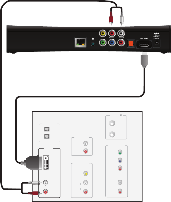
Using a DVI connection with analog audio
The HDMI connector on the set-top box can provide the connection to an HDTV with a
DVI input. If your HDTV has a Digital Visual Interface (DVI) connector, you need an
HDMI-to-DVI cable and a separate analog audio cable.
To connect the set-top box to the TV using an HDMI-to-DVI cable and analog audio
cable:
1. Insert the HDMI end of the cable into the HDMI connector on the set-top box.
2. Insert the 24-pin DVI end of the cable into the DVI connector on the TV.
3. Connect the color-coded analog audio cable to the AUDIO L (white) and R (red)
connectors on the set-top box.
4. Connect the other end of the color-coded analog audio cable to the AUDIO L (white)
and R (red) connectors on the TV.
Television
ANT (75 )
IN
OUT
VIDEO
COMPOSITE
VIDEO IN
L
R
AUDIO
DVI IN
L
R
AUDIO
AUDIO OUT
L
R
OPTICAL IN
Y
PB
PR
COMPONENT
VIDEO IN
L
R
AUDIO
1
2
Set-top box
Analog audio cable
HDMI to DVI cable
YPbPr
OPTICAL
NETWORK RL
AUDIO
VIDEO OUT
WPS
L
R
AUDIO
DVI IN
20
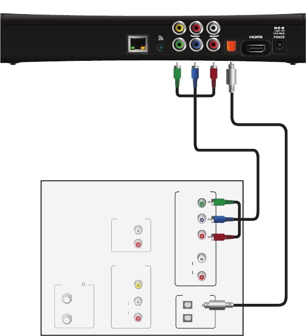
Using a component video connection with digital audio
Component video uses the Y Pb Pr (green, blue, and red) connectors to provide
component video signals to an HDTV or SDTV. You must connect the audio signal
separately using a digital optical audio cable.
To connect the set-top box to the TV using a component video cable and digital audio
cable:
1. Insert the connectors on the color-coded component video cable into the Y Pb Pr
(green, blue, and red) connectors on the set-top box.
2. Insert the other end of the component video cable into the COMPONENT VIDEO Y
Pb Pr (green, blue, and red) connectors on the TV.
3. Connect the fiber optic audio cable to the OPTICAL connector on the set-top box.
4. Connect the other end of the fiber optic audio cable to an available OPTICAL IN
connector on the TV.
Television
ANT (75 )
IN
OUT
VIDEO
COMPOSITE
VIDEO IN
L
R
AUDIO
AUDIO OUT
L
R
OPTICAL IN
Y
P
B
P
R
COMPONENT
VIDEO IN
L
R
AUDIO
1
2
Set-top box
YPbPr
OPTICAL
NETWORK RL
AUDIO
VIDEO OUT
WPS
Y
P
B
P
R
L
R
AUDIO
COMPONENT
VIDEO IN
Component video cable Digital optical
audio cable
21
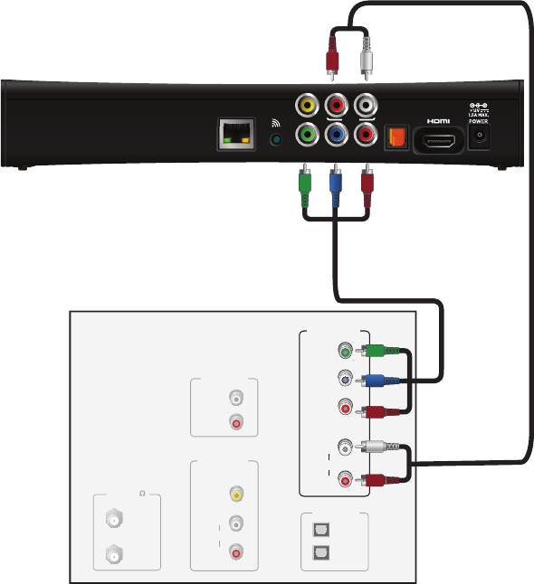
Using a component video connection with analog audio
Component video uses the Y Pb Pr (green, blue, and red) connectors to provide
component video signals to an HDTV or SDTV. You must connect the audio signal
separately using an analog audio cable.
To connect the set-top box to the TV using a component video cable and analog audio
cable:
1. Insert the connectors on the color-coded component video cable into the Y Pb Pr
(green, blue, and red) connectors on the set-top box.
2. Insert the other end of the component video cable into the COMPONENT VIDEO Y
Pb Pr (green, blue, and red) connectors on the TV.
3. Connect the color-coded analog audio cable to the AUDIO L (white) and R (red)
connectors on the set-top box.
4. Connect the other end of the color-coded analog audio cable to the AUDIO L (white)
and R (red) connectors on the TV.
Television
ANT (75 )
IN
OUT
VIDEO
COMPOSITE
VIDEO IN
L
R
AUDIO
AUDIO OUT
L
R
OPTICAL IN
Y
P
B
P
R
COMPONENT
VIDEO IN
L
R
AUDIO
1
2
Set-top box
YPbPr
OPTICAL
NETWORK RL
AUDIO
VIDEO OUT
WPS
Y
P
B
P
R
L
R
AUDIO
COMPONENT
VIDEO IN
Component video cable
Analog audio cable
22
Using a composite video connection
Composite video provides the video connection to an SDTV. You must connect the
audio signal separately.
To connect the set-top box to the TV using a composite video cable:
1. Insert the yellow video connector on the color-coded composite video cable into the
VIDEO OUT (yellow) connector on the set-top box.
2. Insert the other end of the composite video cable into the VIDEO IN (yellow)
connector on the TV.
3. Connect the color-coded audio cable to the AUDIO L (white) and R (red) connectors
on the set-top box.
4. Connect the other end of the color-coded audio cable to the AUDIO L (white) and R
(red) connectors on the TV.
Television
ANT (75 )
IN
OUT
VIDEO
COMPOSITE
VIDEO IN
L
R
AUDIO
AUDIO OUT
L
R
OPTICAL IN
1
2
Set-top box
Audio cable
Composite video cable
YPbPr
OPTICAL
NETWORK RL
AUDIO
VIDEO OUT
WPS
VIDEO
COMPOSITE
VIDEO IN
L
R
AUDIO
23
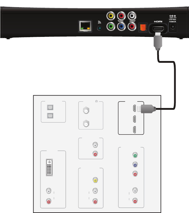
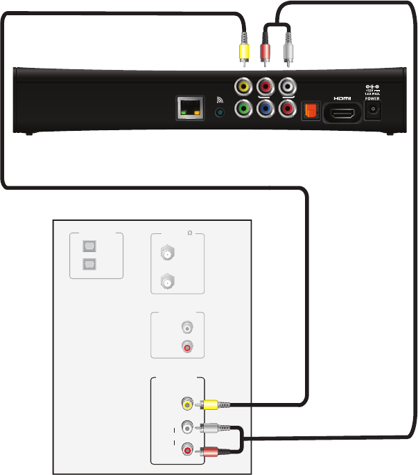
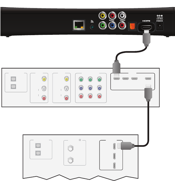
Connecting the set-top box to a home theater system
If your television viewing configuration includes a home theater system, you can
connect the set-top box directly to the home theater system receiver. The following
example uses the HDMI connector to provide the video and audio signals from the set-
top box to the home theater system.
Note: Consult the manual that came with your home theater system for information on
connecting video and audio devices to the home theater receiver.
To connect the set-top box to a home theater receiver using HDMI:
1. Insert one end of the HDMI cable into the HDMI connector on the set-top box.
2. Insert the other end of the HDMI cable into an available HDMI IN connector on the
home theater receiver.
3. Connect a second HDMI cable into an available HDMI OUT connector on the home
theater receiver.
4. Insert the other end of the second HDMI cable into an available HDMI connector on
the TV.
Television
HDMI IN
1
2
3
ANT (75 )
IN
OUT
OPTICAL IN
1
2
Set-top box
HDMI cable
to receiver
HDMI cable
to TV
YPbPr
OPTICAL
NETWORK RL
AUDIO
VIDEO OUT
WPS
Home theater receiver
HDMI
123 OUT
OPTICAL IN
1
2
DVD
VIDEO
L
R
AUDIO
SAT
VIDEO
L
R
AUDIO
COMPONENT
VIDEO
123
24
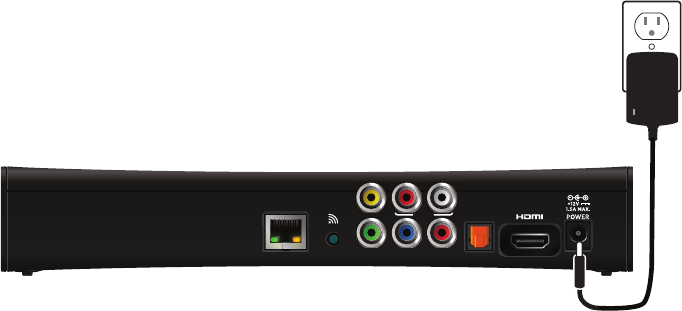
Plug in the set-top box
Use the power adapter included in the container to provide AC power to the set-top
box.
To connect the set-top box to a power supply:
1. Insert the 12 volt connector into the POWER connector on the set-top box.
2. Insert the AC power adapter into an AC electrical outlet.
3. Verify that the LED on the AC power adapter lights green when the set-top box is
receiving power from the wall outlet.
Connecting to the AC power supply
To avoid possible damage to the set-top box or to a connected TV or component, all
AC power cords must be plugged into properly wired outlets. As with all electrical
products, connection to faulty or defective components, or the failure to connect the
apparatus to a properly wired outlet, may cause sparking, property damage, or
damage to any TV or other component connected to the apparatus and pose a fire
hazard.
If you are in any doubt about the power supply lead, its plug or its connection, or are
not certain that the electrical outlets you are using are properly wired and grounded,
consult a qualified electrician before proceeding any further.
YPbPr
OPTICAL
NETWORK RL
AUDIO
VIDEO OUT
WPS
Set-top box
Power supply unit
AC electrical
outlet
25
Troubleshooting and Support
This section contains troubleshooting tips and answers to common issues and
questions.
Troubleshooting
Use the information in this section to identify and resolve issues with the set-top box. If
you need further assistance, contact your service provider.
No Picture
•Verify that the TV is turned on.
•Verify that nothing is blocking the path from your remote control to the front panel of
the set-top box.
•Verify that your remote control is set to operate the set-top box (rather than another
component in your set up). If the remote control does not operate the set-top box,
replace the batteries in your remote control.
•If the set-top box is plugged into a switched power outlet, verify that the switch is on.
Check the LED on the power supply unit. It lights green when the set-top box is
receiving power from the wall outlet. Verify that the Power light on the front panel of
the set-top box is green.
•Verify that all cables are properly connected.
•If WPS (Wi-Fi Protected Setup) is used to connect to the home network, verify that
the network’s wireless gateway has the WPS configuration setting enabled. To
initiate the connection, press the WPS button on the set-top box, and then press the
WPS button on the home network gateway.
•Verify that the Link light on the receiver is green to indicate that the receiver is
connected to the home network. If the receiver is not connected to the home
network, do the following:
– Check the Ethernet cable to the NETWORK connector to verify that the cable to
your home network is connected properly.
– If a wireless connection is used, verify that the WPS indicator light on the front
panel displays solid green for five minutes after pairing is successful. If pairing
was unsuccessful, the WPS indicator light blinks green then shuts off without
displaying solid green. If this occurs, wait two minutes and then press the WPS
button on the set-top box again, followed by pressing the WPS button on the
gateway.
If necessary, reboot the receiver by unplugging the AC power adapter from the
electrical outlet, waiting ten seconds, and then plugging it back into the electrical
outlet.
26
•If your system includes an external DVR recorder or home theater receiver, verify
that you have properly connected the device to the set-top box. Verify that the
Record light on the set-top box lights red when DVR recording is in progress.
•Verify that you are using the proper input selection on your TV or home theater
receiver. If you are using a component video connection, make sure that the TV
display capability settings are appropriate for your TV. If you are using the HDMI
connection, make sure the connection goes directly from your set-top box to your
TV (or your home theater receiver). If the set-top box detects that the link is not
secure, your receiver will not transmit a picture.
•Verify that the HD light on the set-top box is blue when the set-top box receives a
high-definition input signal.
•Verify that the set-top box is set to the proper screen type and resolution. If your TV
is a 16:9 TV, you can use the Auto Pillarbox setting to add black borders to 4:3
transmissions, so that the picture is not stretched.
No Color or Incorrect Color
•Verify that the current TV program is broadcast in color.
•Adjust the TV color controls.
•If you are using a component video connection, check that all connectors are
connected completely and properly.
•If you are using a component video connection and your HDTV has only RGB or
RGB-HV connectors, you must use an adapter. You can obtain the adapter through
an electronics retailer.
•Some programs may include copy protection, which means that if your set-top box
is connected to your HDTV through the component video connectors, the picture is
downgraded to standard TV quality. To prevent this from happening, use an HDMI
connection, if it is supported on your TV.
No Sound
•Verify that all audio and video cables are connected securely and correctly. If your
system includes an external DVD recorder or home theater receiver, verify that you
have properly connected the device to the set-top box.
•Verify that the volume is turned up.
•Verify that the mute function is not on.
•Verify that you are using the proper input selection on your TV or home theater
receiver.
27
Screen burn-in
Images such as letterbox bars or side bars, bright closed-captioning backgrounds,
station logos, or any other stationary images may cause the display in your HDTV to
age unevenly. This is known as screen burn-in. Refer to the owner’s manual that came
with your HDTV for more information about avoiding screen burn-in.
CAUTION: Do not display the same fixed images on your HDTV screen for extended
periods of time.
Frequently asked questions
What is digital television?
Digital television (DTV) is a significant leap forward in television technology compared
to analog television that has been widely available since the 1940s. DTV is delivered
and displayed using digital encoding, similar to the way a computer operates. By using
digital technology, there is no variation in picture and sound quality from the origination
point until it is displayed on your television. You always receive a high-quality picture
without the wavy lines or static that you might get from a weak analog signal. Another
feature of digital television is digital surround sound using Dolby Digital technology,
which is the same technology used to produce the sound you hear in movie theaters.
What is standard definition television?
Standard definition television (SDTV) is basic digital television programming delivered
by your service provider. Typically, the SDTV screen is the same, nearly square shape
as an analog television screen. Digital images on an SDTV set are crisp and clear, and
noticeably better than on a standard analog television set using an antenna.
What is high definition television?
High definition television (HDTV) is an improved way to send and receive television
broadcast signals. HDTV images are made up of pixels that are much smaller and
closer together than those used in standard analog television, and there are millions of
them. Thus, HDTV can display five to six times the detail of analog television to deliver
picture quality that is much more realistic, dimensional, and precise. SDTV programs
can be viewed on an HDTV.
Are local TV stations or other programmers broadcasting in HDTV?
Many local TV stations and programmers are transmitting digital signals. However,
transmitting a digital signal does not mean transmitting an HDTV signal. Some stations
are using the new bandwidth to broadcast several standard definition channels. Most
stations and programmers, once they begin broadcasting in digital, are offering HD
content from their parent network (for example, CBS, ABC, NBC, Fox, and PBS).
Contact your service provider for more information.
Why aren’t all the shows I watch in high definition?
A high definition program must originate in HD format and be broadcast in HD format.
Having an HDTV system does not mean that everything you watch will be viewed in
high definition. Getting the signal from a digital source also does not mean it is high
definition.
28
What is HDMI and does it support Dolby Digital 5.1 audio?
HDMI (High Definition Multimedia Interface) is an uncompressed, all-digital audio/
video interface. The Dolby Digital audio format can provide up to 5.1 separate
channels of surround sound, and is the standard used for DVD-Video. HDMI supports
standard, enhanced, or high-definition video, plus multi-channel digital audio, such as
Dolby Digital audio, on a single cable.
Picture formats
What is the difference between a standard-screen and a wide-screen HDTV?
The type of screen your HDTV has (wide-screen or standard-screen) determines how
the set-top box displays programs on the screen. The picture format for an HDTV is a
combination of aspect ratio and screen resolution and is different for standard-screen
and wide-screen HDTVs.
What is aspect ratio?
An aspect ratio is the ratio of the width to the height of the TV screen. The aspect
ratios differ because the television industry manufactures both standard-screen and
wide-screen HDTVs to appeal to consumer viewing preferences. The two aspect ratios
are as follows:
•On standard-screen (4:3) HDTVs, the programming is displayed in letterbox format
in the middle of the screen. There are bars surrounding the picture.
•On wide-screen (16:9) HDTVs, the programming is displayed on the full screen.
What is the screen resolution?
The screen resolution indicates the amount of detail that the picture displays.
Resolution is identified by the number of display lines on the screen. The techniques
that an HDTV uses to “paint” the picture on the screen are referred to as progressive
and interlaced.
With the progressive scanning method, the lines are drawn on the screen one at a time
in sequential order. Progressive scanning results in a more detailed image on the
screen and is also less susceptible to the flicker commonly associated with interlaced
scanning. The interlaced method involves refreshing pixels in alternation, first the odd
lines and then the even lines.
For advanced setup, select the screen resolution that your TV can support. Refer to
your Feature Guide and HDTV owner’s manuals to choose the proper screen
resolution for your setup. For example, a screen resolution of 1080i indicates that the
screen shows 1080 lines on an interlaced display, and 720p indicates that the screens
shows 720 lines on a progressive-scan display.
29
Compliance Information
Regulatory information
CAUTION: Do not attempt to modify your set-top box without written authorization from the
manufacturer. Unauthorized modification could void your authority to operate your set-top box.
Trade Name: Pace Americas
Responsible Party: 2Wire, Inc. DBA Pace Americas
Address: 1764 Automation Parkway, San Jose, CA 95131
Phone: (408) 428-9500
Declaration of Conformity
FCC / Industry Canada Compliance
This device has been tested and certified as compliant with the regulations and guidelines set
forth in the Federal Communication commission - FCC part 15 and Industry Canada - ICES003
and RSS-210 Radio and telecommunication regulatory requirements / Le présent materiel est
conforme aux specifications techniques applicables d'Industrie Canada. Cet appareil numérique
de la classe [*] est conforme à la norme NMB-003 du Canada.
Manufacturer: 2Wire, Inc. DBA Pace Americas
Model(s): IPW8000
Part 15 of FCC Rules / IC RSS-210 – RSS GEN
This device complies with part 15 of the FCC Rules and Industry Canada license-exempt RSS
standard(s). Operation is subject to the following two conditions:
(1) this device may not cause harmful interference, and
(2) this device must accept any interference received, including interference that may cause
undesired operation of the device.
Le présent appareil est conforme aux normes CNR d'Industrie Canada applicables aux appareils
radio exempts de licence. L'exploitation est autorisée aux deux conditions suivantes:
(1) l'appareil ne doit pas produire de brouillage, et
(2) l'utilisateur de l'appareil doit accepter tout brouillage radioélectrique subi, même si le
brouillage est susceptible d'en compromettre le fonctionnement.
This equipment has been tested and found to comply with the limits for a Class B digital device,
pursuant to Part 15 of the FCC Rules. These limits are designed to provide reasonable protection
against harmful interference in a residential installation. This equipment generates, uses, and can
radiate radio-frequency energy and, if not installed and used in accordance with the instructions,
may cause harmful interference to radio communications. However, there is no guarantee that
interference will not occur in a particular installation. If this equipment does cause harmful
interference to radio or television reception, which can be determined by turning the equipment
off and on, you are encouraged to try to correct the interference by one or more of the following
measures:
•Reorient or relocate the receiving antenna.
•Increase the separation between the equipment and the receiver.
•Connect the equipment to an outlet on a circuit that is different from the circuit used by the
receiver.
•Consult your dealer or an experienced radio/TV technician for help.
30
CAUTION: Changes or modifications not expressly approved by the party responsible for
compliance could void your authority to operate this equipment. Failure to heed the Safety
Information provided by failing to connect to a properly wired outlet may void the manufacturer's
warranty.
Users should be advised that high-power radars are allocated as primary users (i.e. priority
users) of the bands 5250-5350 MHz and 5470-5725 MHz and that these radars could cause
interference and/or damage to the LE-LAN device.
Les utilisateurs doivent être avisés que les radars de haute puissance sont désignés utilisateurs
principaux (c.-à-d., qu'ils ont la priorité) pour les bandes 5250-5350 MHz et 5650-5850 MHz et
que ces radars peuvent causer du brouillage et/ou des dommages aux dispositifs LAN-EL.
The device for operation in the band 5150-5250MHz is only for indoor use to reduce the potential
for harmful interference to co-channel mobile satellite systems.
Les dispositifs fonctionnant dans la bande 5150-5250 MHz sont réservés uniquement pour une
utilisation à l'intérieur afin de réduire les risques de brouillage préjudiciable aux systèmes de
satellites mobiles utilisant les mêmes canaux.
Under Industry Canada regulations, this radio transmitter may only operate using an antenna of a
type and maximum (or lesser) gain approved for the transmitter by Industry Canada. To reduce
potential for radio interference to other users, the antenna type and its maximum gain should be
so chosen that the equivalent isotropically radiated power (e.i.r.p.) is not more than that
necessary for successful communication.
Conformément à la réglementation d'Industrie Canada, le présent émetteur radio peut
fonctionner avec une antenne d'un type et d'un gain maximal (ou inférieur) approuvé pour
l'émetteur par Industrie Canada. Dans le but de réduire les risques de brouillage radioélectrique à
l'intention des autres utilisateurs, il faut choisir le type d'antenne et son gain de sorte que la
puissance isotrope rayonnée équivalente (p.i.r.e.) ne dépasse pas l'intensité nécessaire à
l'établissement d'une communication satisfaisante.
MPE/SAR/RF Exposure Information
This device was verified for RF exposure and found to comply with Council Recommendation
1999/519/EC and FCC OET-65 RF exposure requirements. This equipment complies with FCC
radiation exposure limits set forth for an uncontrolled environment.
WARNING: While this device is in operation, a separation distance of at least 20 cm (8 inches)
must be maintained between the radiating antenna inside the EUT and the bodies of all persons
exposed to the transmitter in order to meet the FCC RF exposure guidelines. Making changes to
the antenna or the device is not permitted. Doing so may result in the installed system exceeding
RF exposure requirements. This device must not be co-located or operated in conjunction with
any other antenna or radio transmitter.

www.pace.com
Pace and the Pace logo are registered trademarks of Pace plc. All other trademarks are the
property of their respective owners.
© 2013 Pace plc. All rights reserved.
Pace provides no warranty with regard to this manual, the software, or other information contained
herein, and hereby expressly disclaims any implied warranties of merchantability or fitness for any
particular purpose with regard to this manual, the software, or such other information, in no event
shall Pace be liable for any incidental, consequential, or special damages, whether based on tort,
contract, or otherwise, arising out of or in connection with this manual, the software, or other
information contained herein or the use thereof.
504T6630001
Trademarks and licenses
This product incorporates copyright protection technology that is protected by U.S. patents and
other intellectual property rights. Use of this copyright protection technology must be authorized
by Rovi corporation, and is intended for home and other limited pay-per-view uses only unless
otherwise authorized by Rovi corporation. Reverse engineering or disassembly is prohibited.
Manufactured under license from Dolby Laboratories. Dolby and the double-D symbol are
trademarks of Dolby Laboratories.
HDMI, the HDMI Logo and High-Definition Multimedia Interface are trademarks or registered
trademarks of HDMI Licensing LLC in the United States and other countries.
Open source licenses
The software contained in this product may be covered by certain components consisting of free
software or open source software. A list of these components and a copy of the relevant copyright
notices and license term notices that are required by such licenses are available at this web page:
http://www.pace.com/opensource/license
®