ARRIS NVG34NX4 NVG34X Series VDSL2 Gateway User Manual rev
ARRIS Group, Inc. NVG34X Series VDSL2 Gateway rev
UserManual.wiki
>
ARRIS
>
NVG34NX4 User Manual
>
User Manual_rev.pdf
Contents
1.
User Manual (Statement)_rev 2.pdf
2.
User Manual_rev.pdf
User Manual_rev.pdf
Navigation menu
Upload a User Manual
Namespaces
Wiki Guide
HTML
PDF
Info
Views
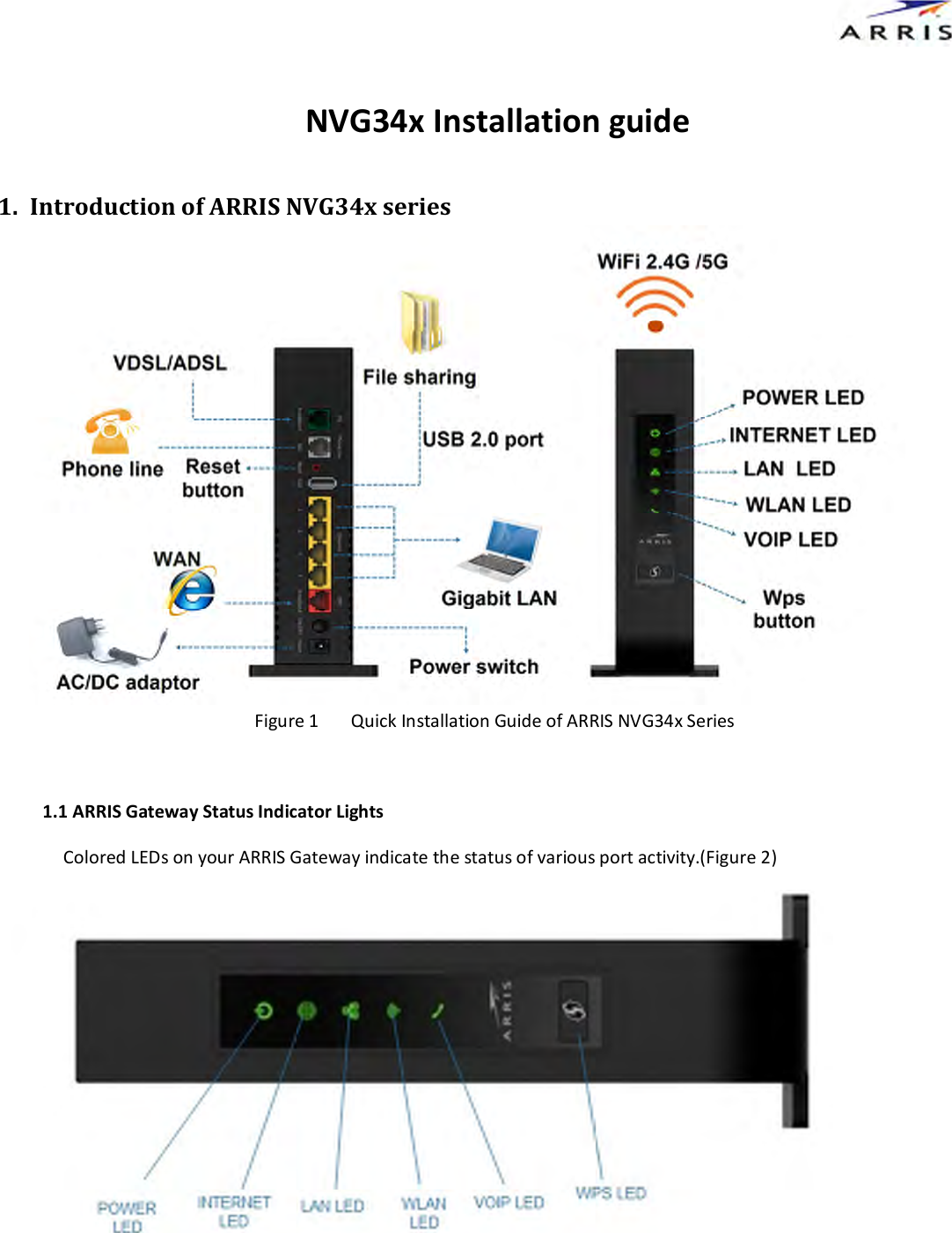
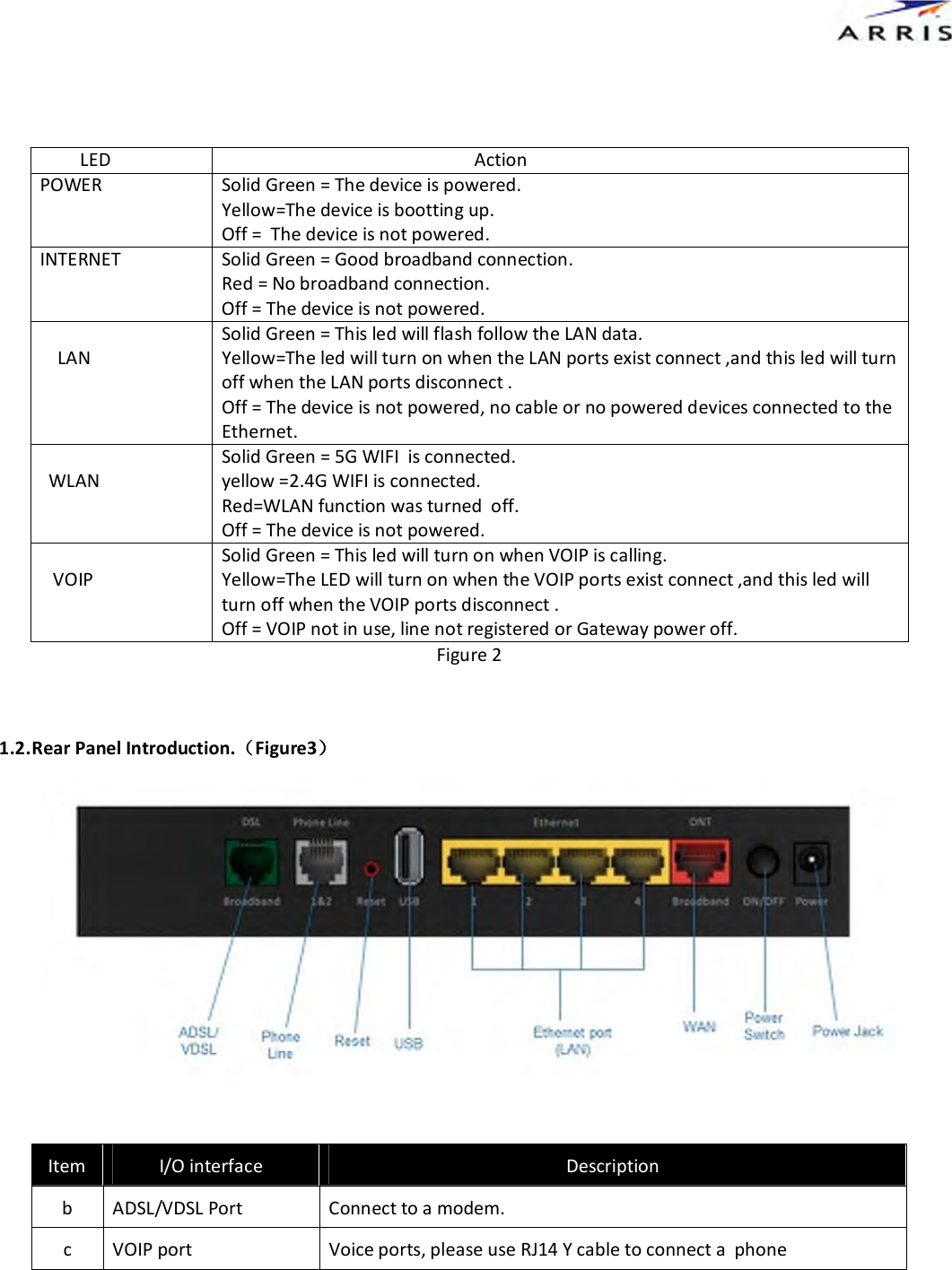
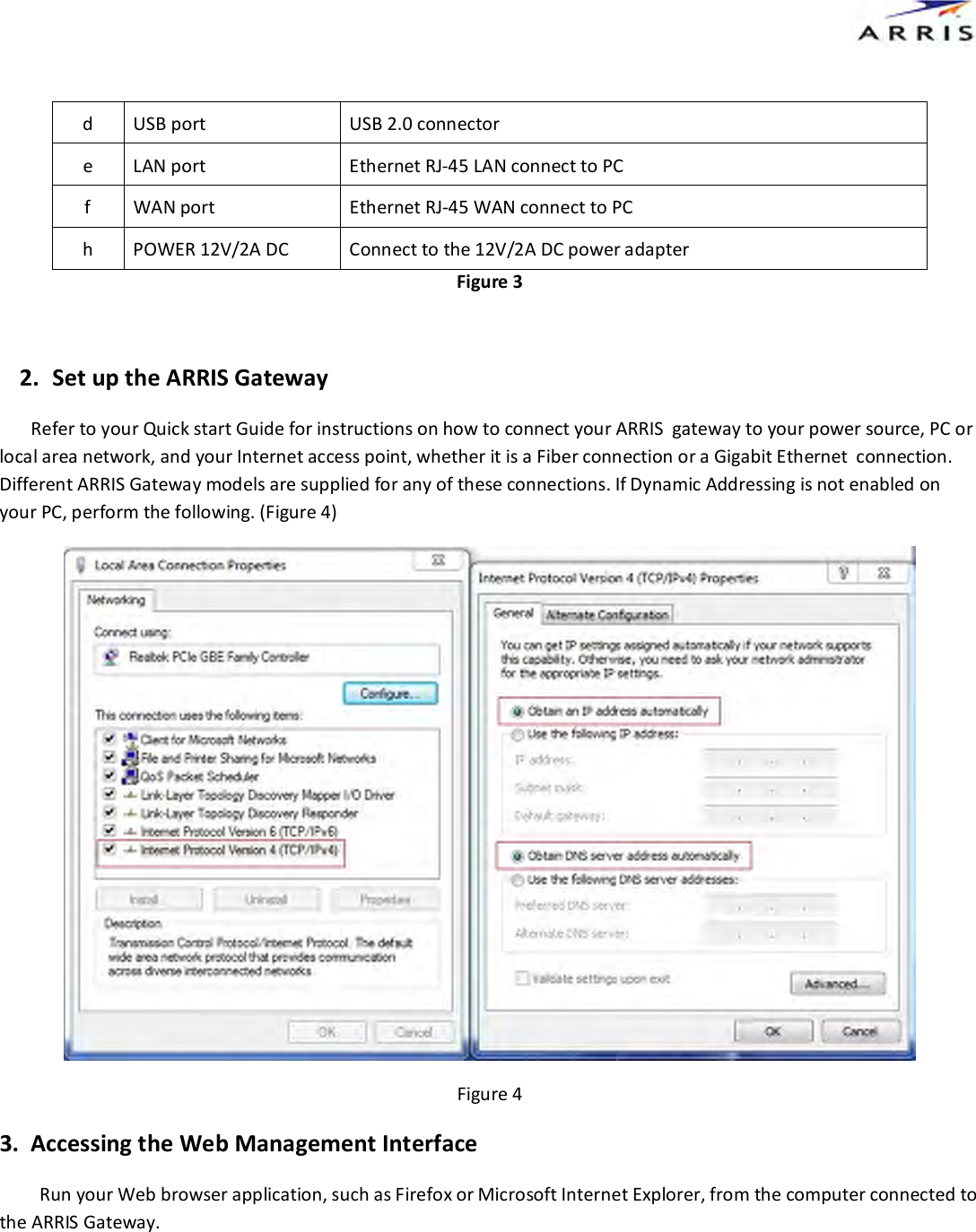
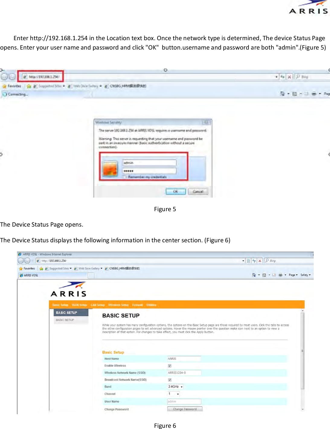
User Manual
Discussion / Help
Navigation