ARRIS NVG34NX4 NVG34X Series VDSL2 Gateway User Manual rev
ARRIS Group, Inc. NVG34X Series VDSL2 Gateway rev
ARRIS >
Contents
- 1. User Manual (Statement)_rev 2.pdf
- 2. User Manual_rev.pdf
User Manual_rev.pdf
NVG34x Installation guide
1. Introduction of ARRIS NVG34x series
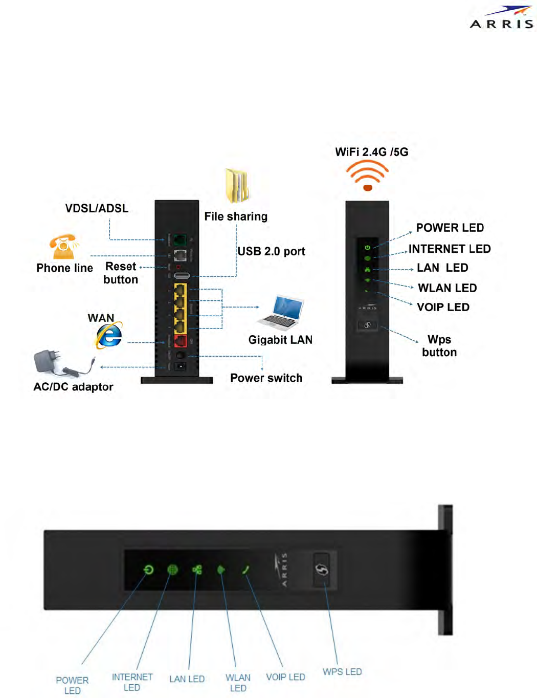
Figure 1 Quick Installation Guide of ARRIS NVG34x Series
1.1 ARRIS Gateway Status Indicator Lights
Colored LEDs on your ARRIS Gateway indicate the status of various port activity.(Figure 2)
LED
Action
POWER
Solid Green = The device is powered.
Yellow=The device is bootting up.
Off = The device is not powered.
INTERNET
Solid Green = Good broadband connection.
Red = No broadband connection.
Off = The device is not powered.
LAN
Solid Green =
This led will flash follow the
LAN
data.
Yellow=The led will turn on when the LAN ports exist connect ,and this led will turn
off when the LAN ports disconnect .
Off = The device is not powered, no cable or no powered devices connected to the
Ethernet.
WLAN
Solid Green =
5G
WIFI
is
connected
.
yellow =2.4G WIFI is connected.
Red=WLAN function was turned off.
Off = The device is not powered.
VOIP
Solid Green = T
his led will turn on when VOIP is calling.
Yellow=The LED will turn on when the VOIP ports exist connect ,and this led will
turn off when the VOIP ports disconnect .
Off = VOIP not in use, line not registered or Gateway power off.
Figure 2
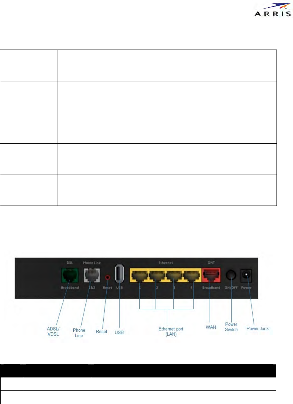
1.2. Rear Panel Introduction.(Figure3)
Item I/O interface Description
b ADSL/VDSL Port Connect to a modem.
c VOIP port Voice ports, please use RJ14 Y cable to connect a phone
d USB port USB 2.0 connector
e LAN port Ethernet RJ-45 LAN connect to PC
f WAN port Ethernet RJ-45 WAN connect to PC
h POWER 12V/2A DC Connect to the 12V/2A DC power adapter
Figure 3
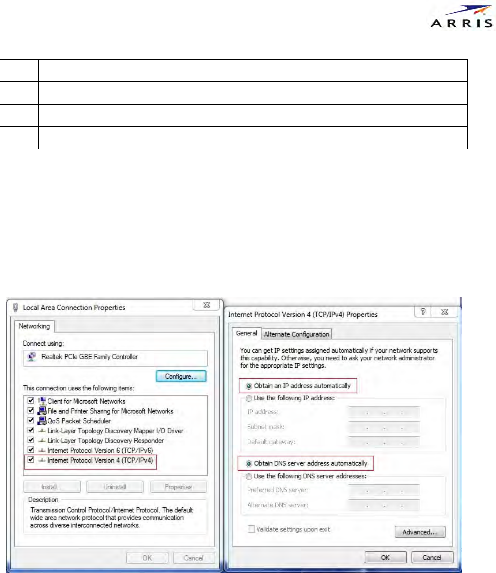
2. Set up the ARRIS Gateway
Refer to your Quick start Guide for instructions on how to connect your ARRIS gateway to your power source, PC or
local area network, and your Internet access point, whether it is a Fiber connection or a Gigabit Ethernet connection.
Different ARRIS Gateway models are supplied for any of these connections. If Dynamic Addressing is not enabled on
your PC, perform the following. (Figure 4)
Figure 4
3. Accessing the Web Management Interface
Run your Web browser application, such as Firefox or Microsoft Internet Explorer, from the computer connected to
the ARRIS Gateway.
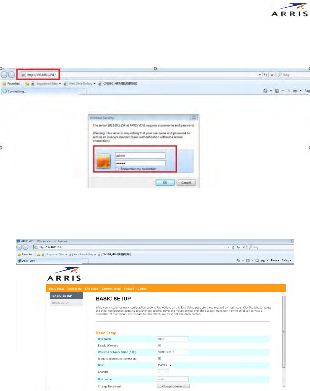
Enter http://192.168.1.254 in the Location text box. Once the network type is determined, The device Status Page
opens. Enter your user name and password and click "OK" button.username and password are both "admin".(Figure 5)
Figure 5
The Device Status Page opens.
The Device Status displays the following information in the center section. (Figure 6)
Figure 6
3.1 Links Bar
The links bar at the top of each page allows you to configure different aspects of the features displayed on the page.
(Figure 7)
Figure 7
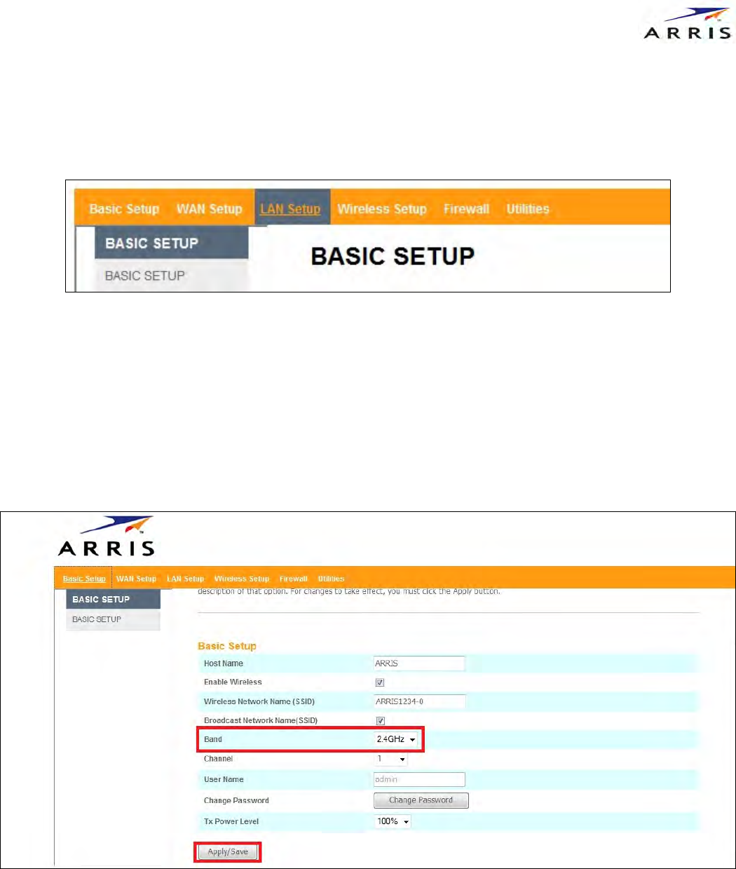
3.2 Basic Setup
Click "Basic Setup",you can change user name and password,and other setting as the figure show.About WIFI
setting ,select "2.4G"or "5G"on "Band",then click "Apply/Save".(Figure 8)
Figure 8
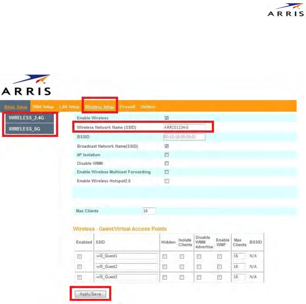
3.3 WIFI setting
Click “Wireless Setup” sub menu “Wireless 2.4G”or "Wireless 5G". Change WIFI SSID in "Wireless Network Name",then
click "Apply/Save".(Figure 9)
Figure 9
Click sub menu ''SECURITY" to change WIFI password .select "WPA2-PSK" in "Network Authentication",then change
password in "WPA/WAPI pass phrase"(Figure 10)
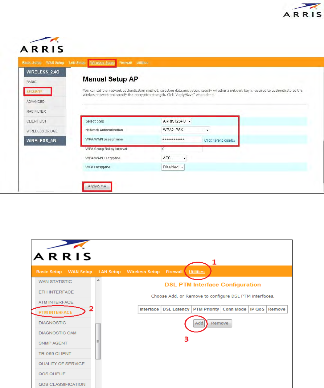
Figure 10
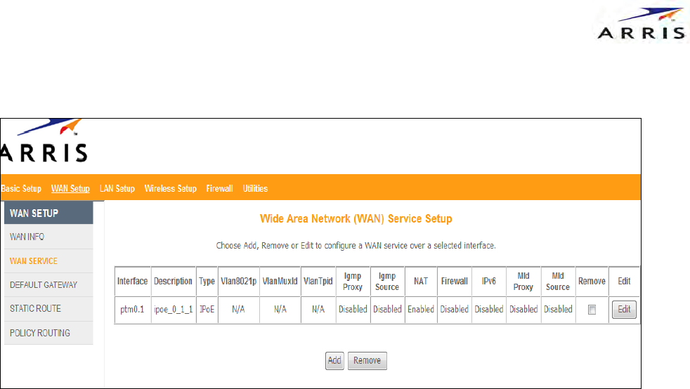
3.4 Setup VDSL
click 'Utilities' and select 'PTM INTERFACE'.Click 'add' and configure a PTM flow then apply.
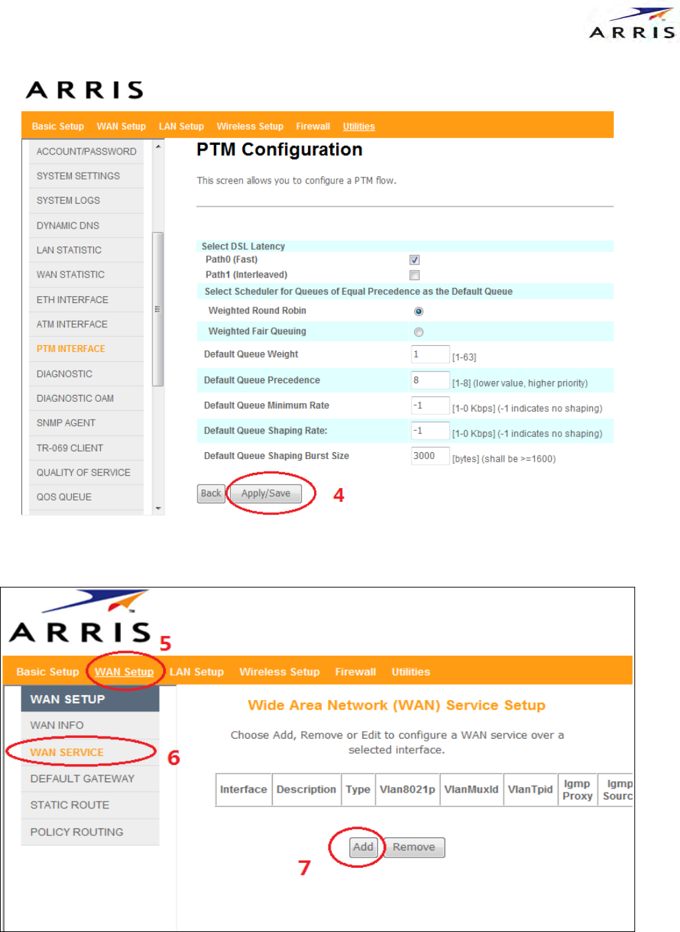
Click 'WAN SETUP' select 'wan service', then click 'add'. If you only want to set xDSL interface with default configure.
Click next, next....and apply in the end.
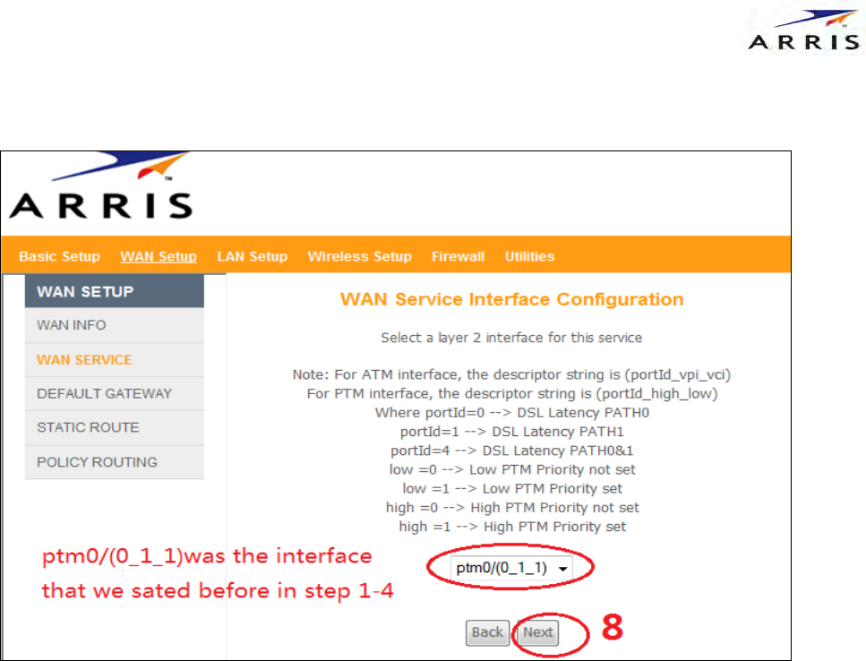
Select the interface you have set in step '1', then next.
Select WAN service type under your environment. Here I select IPOE, then next.
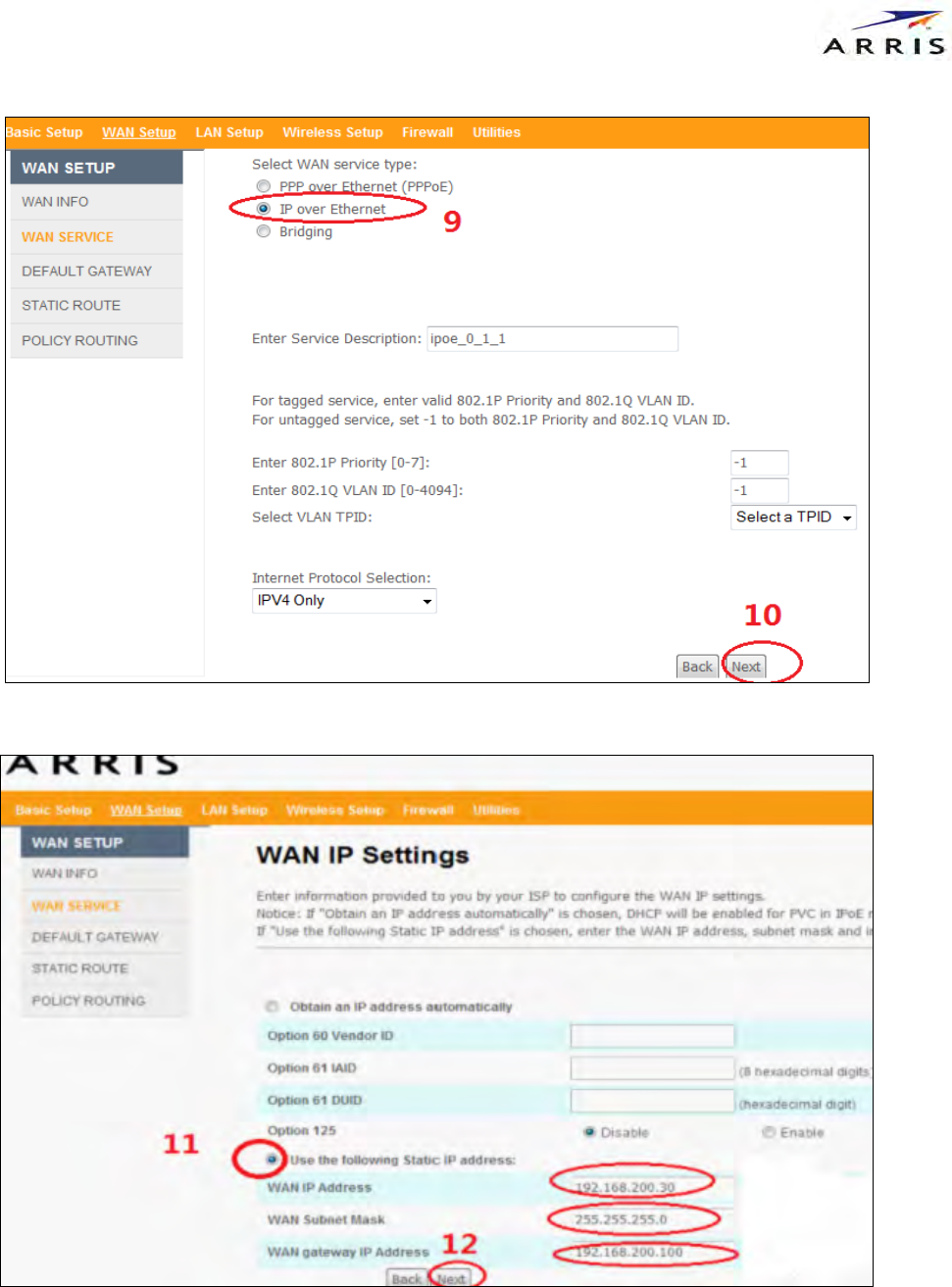
Wan IP set ... next and next.
Default gateway...next.
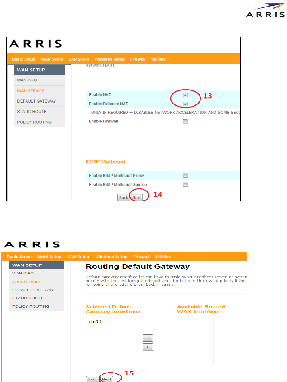
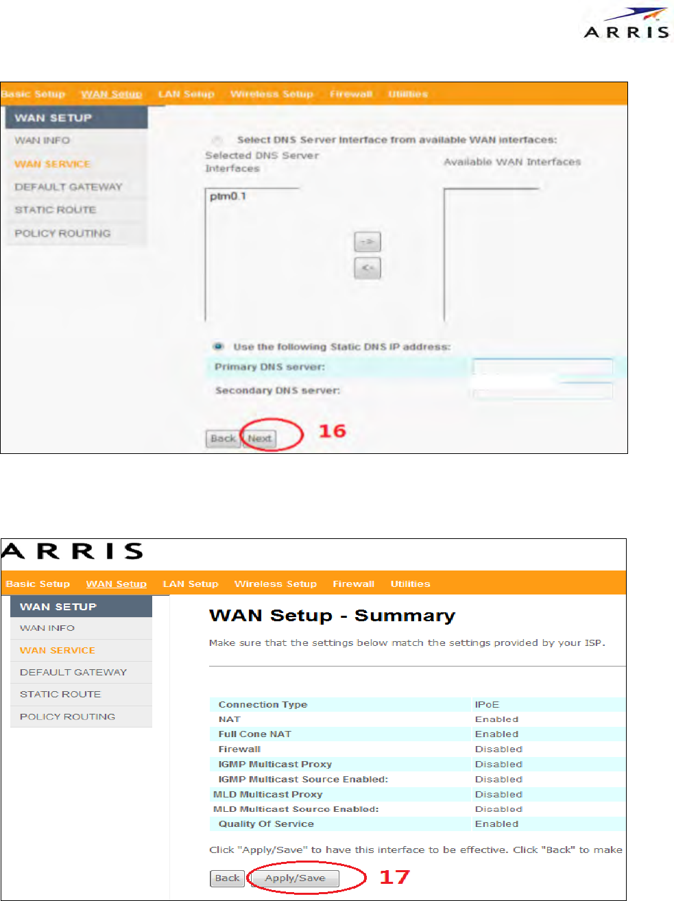
In the end, click ”Apply”. You can see this