ARRIS NVG510 Wireless Voice Gateway, ADSL2+ User Manual Administrator s Handbook V9 0 6 NVG510 att
ARRIS Group, Inc. Wireless Voice Gateway, ADSL2+ Administrator s Handbook V9 0 6 NVG510 att
ARRIS >
User Manual
b
Motorola
®
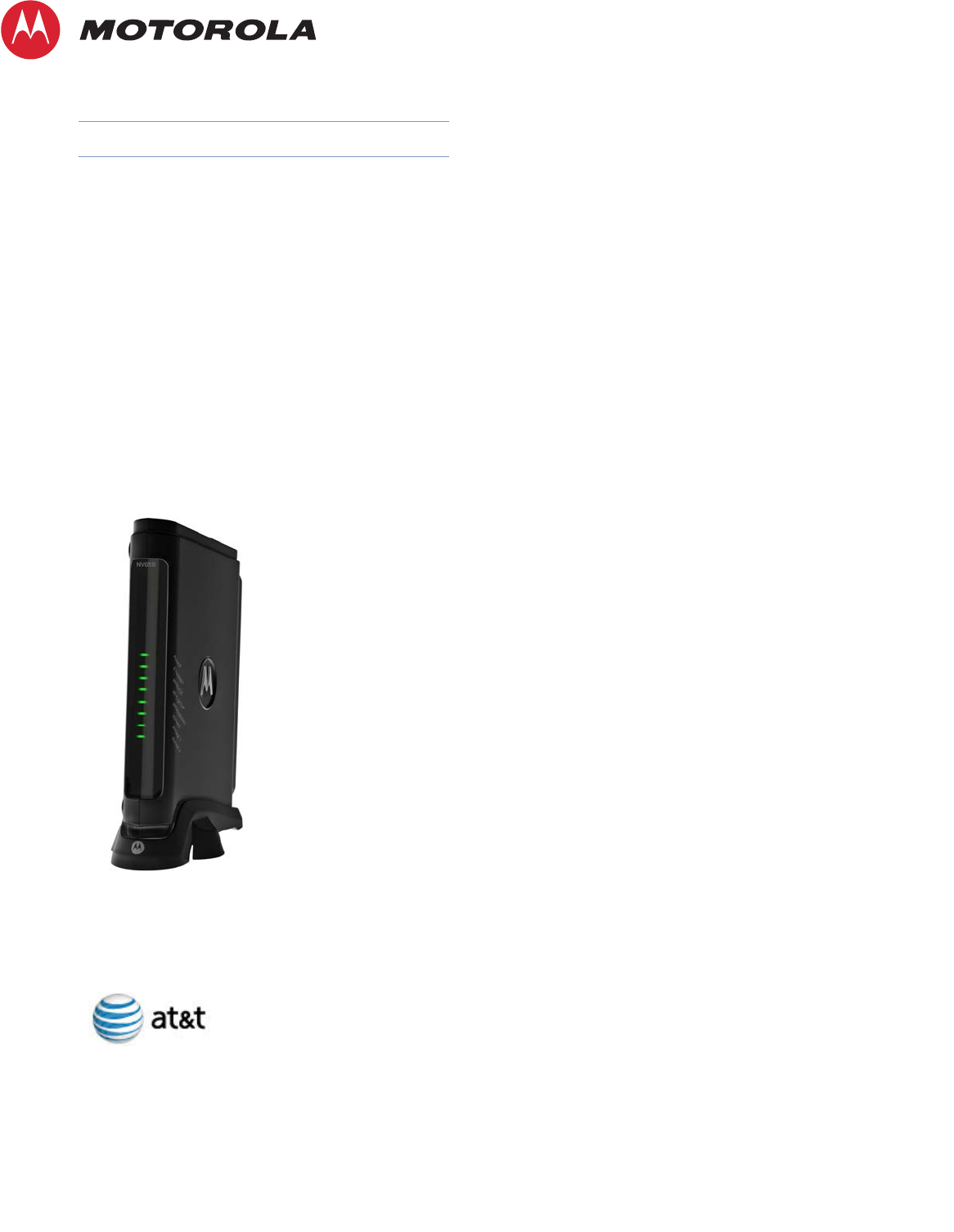
NVG510 Voice Gateway
Motorola
®
Embedded Software Version 9.0.6
Administrator’s Handbook

Administrator’s Handbook
Copyright
©2011 Motorola Mobility, Inc. All rights reserved. MOTOROLA, and the Stylized M logo are trademarks or registered trademarks of Motorola Trademark Holdings, LLC. All
other product or service names are the property of their respective owners. No part of this publication may be reproduced in any form or by any means or used to make
any derivative work (such as translation, transformation, or adaptation) without written permission from Motorola Mobility, Inc. Motorola reserves the right to revise this
publication and to make changes in content from time to time without obligation on the part of Motorola to provide notification of such revision or change. Motorola pro-
vides this guide without warranty of any kind, implied or expressed, including, but not limited to, the implied warranties of merchantability and fitness for a particular pur-
pose. Motorola may make improvements or changes in the product(s) described in this manual at any time.
©2010 Motorola Mobility, Inc. All rights reserved. MOTOROLA, and the Stylized M logo are trademarks or registered trademarks of Motorola Trademark Holdings, LLC. All
other product or service names are the property of their respective owners. No part of this publication may be reproduced in any form or by any means or used to make
any derivative work (such as translation, transformation, or adaptation) without written permission from Motorola Mobility, Inc. Motorola reserves the right to revise this
publication and to make changes in content from time to time without obligation on the part of Motorola to provide notification of such revision or change. Motorola pro-
vides this guide without warranty of any kind, implied or expressed, including, but not limited to, the implied warranties of merchantability and fitness for a particular pur-
pose. Motorola may make improvements or changes in the product(s) described in this manual at any time.
EXCEPT AS INDICATED IN THE APPLICABLE SYSTEM PURCHASE AGREEMENT, THE SYSTEM, DOCUMENTATION AND SERVICES ARE PROVIDED “AS IS”, AS AVAIL-
ABLE, WITHOUT WARRANTY OF ANY KIND. MOTOROLA MOBILITY, INC. DOES NOT WARRANT THAT THE SYSTEM WILL MEET CUSTOMER'S REQUIREMENTS, OR THAT
THEIR OPERATION WILL BE UNINTERRUPTED OR ERROR-FREE, OR THAT ANY ERRORS CAN OR WILL BE FIXED. MOTOROLA MOBILITY, INC. HEREBY DISCLAIMS ALL
OTHER WARRANTIES, EXPRESS OR IMPLIED, ORAL OR WRITTEN, WITH RESPECT TO THE SYSTEM AND SERVICES INCLUDING, WITHOUT LIMITATION, ALL IMPLIED
WARRANTIES OF TITLE, NON-INFRINGEMENT, INTEGRATION, MERCHANTABILITY OR FITNESS FOR ANY PARTICULAR PURPOSE AND ALL WARRANTIES ARISING
FROM ANY COURSE OF DEALING OR PERFORMANCE OR USAGE OF TRADE.
EXCEPT AS INDICATED IN THE APPLICABLE SYSTEM PURCHASE AGREEMENT, MOTOROLA MOBILITY, INC. SHALL NOT BE LIABLE CONCERNING THE SYSTEM OR
SUBJECT MATTER OF THIS DOCUMENTATION, REGARDLESS OF THE FORM OF ANY CLAIM OR ACTION (WHETHER IN CONTRACT, NEGLIGENCE, STRICT LIABILITY OR
OTHERWISE), FOR ANY (A) MATTER BEYOND ITS REASONABLE CONTROL, (B) LOSS OR INACCURACY OF DATA, LOSS OR INTERRUPTION OF USE, OR COST OF PROCUR-
ING SUBSTITUTE TECHNOLOGY, GOODS OR SERVICES, (C) INDIRECT, PUNITIVE, INCIDENTAL, RELIANCE, SPECIAL, EXEMPLARY OR CONSEQUENTIAL DAMAGES
INCLUDING, BUT NOT LIMITED TO, LOSS OF BUSINESS, REVENUES, PROFITS OR GOODWILL, OR (D) DIRECT DAMAGES, IN THE AGGREGATE, IN EXCESS OF THE FEES
PAID TO IT HEREUNDER FOR THE SYSTEM OR SERVICE GIVING RISE TO SUCH DAMAGES DURING THE 12-MONTH PERIOD PRIOR TO THE DATE THE CAUSE OF ACTION
AROSE, EVEN IF COMPANY HAS BEEN ADVISED OF THE POSSIBILITY OF SUCH DAMAGES. THESE LIMITATIONS ARE INDEPENDENT FROM ALL OTHER PROVISIONS OF
THIS AGREEMENT AND SHALL APPLY NOTWITHSTANDING THE FAILURE OF ANY REMEDY PROVIDED HEREIN.
All Motorola Mobility, Inc. products are furnished under a license agreement included with the product. If you are unable to locate a copy of the license agreement,
please contact Motorola Mobility, Inc.
NOTE: THIS IS DRAFT DOCUMENTATION INTENDED FOR TESTING AND EVALUATIVE REVIEW. IT MAY CON-
TAIN ERRORS. IT SHOULD NOT BE CONSIDERED SUITABLE FOR USE IN A PRODUCTION ENVIRONMENT.
Motorola Mobility, Inc.
600 North U.S. Highway 45
Libertyville, Illinois 60048 USA
Telephone: +1 847 523 5000
Part Number
58XXXX-001-00d8 rev a
V9.0.6-sku 64

Table of Contents
Table of Contents
CHAPTER 1
Introduction
. . . . . . . . . . . . . . . . . . . . . . . . . . . . . . . . . . . . . . . . . . . . . . . . 7
About Motorola
®
Documentation
. . . . . . . . . . . . . . . . . . . . . . . . 7
Documentation Conventions
. . . . . . . . . . . . . . . . . . . . . . . . . . . 8
General. . . . . . . . . . . . . . . . . . . . . . . . . . . . . . . . . . . . . . . . . . . . . . . . . . 8
Internal Web Interface . . . . . . . . . . . . . . . . . . . . . . . . . . . . . . . . . . . . . . 8
Command Line Interface . . . . . . . . . . . . . . . . . . . . . . . . . . . . . . . . . . . . 8
Organization
. . . . . . . . . . . . . . . . . . . . . . . . . . . . . . . . . . . . . . . 9
A Word About Example Screens
. . . . . . . . . . . . . . . . . . . . . . . . 9
CHAPTER 2
Device Configuration
. . . . . . . . . . . . . . . . . . . . . . . . . . . . . . . . . . . . .11
Important Safety Instructions
. . . . . . . . . . . . . . . . . . . . . . . . . . 12
POWER SUPPLY INSTALLATION. . . . . . . . . . . . . . . . . . . . . . . . . . . . 12
TELECOMMUNICATION INSTALLATION . . . . . . . . . . . . . . . . . . . . . . 12
PRODUCT VENTILATION . . . . . . . . . . . . . . . . . . . . . . . . . . . . . . . . . . 12
Wichtige Sicherheitshinweise
. . . . . . . . . . . . . . . . . . . . . . . . . 13
NETZTEIL INSTALLIEREN . . . . . . . . . . . . . . . . . . . . . . . . . . . . . . . . . 13
INSTALLATION DER TELEKOMMUNIKATION . . . . . . . . . . . . . . . . . . 13
Motorola
®
Gateway Status Indicator Lights
. . . . . . . . . . . . . . . 14
Set up the Motorola Gateway
. . . . . . . . . . . . . . . . . . . . . . . . . 16
Accessing the Web Management Interface
. . . . . . . . . . . . . . . 19
Device Status page
. . . . . . . . . . . . . . . . . . . . . . . . . . . . . . . . . 21
Device Access Code . . . . . . . . . . . . . . . . . . . . . . . . . . . . . . . . . . . . . . 21
Tab Bar
. . . . . . . . . . . . . . . . . . . . . . . . . . . . . . . . . . . . . . . . . . 23
Help
. . . . . . . . . . . . . . . . . . . . . . . . . . . . . . . . . . . . . . . . . . . . . 23
Links Bar
. . . . . . . . . . . . . . . . . . . . . . . . . . . . . . . . . . . . . . . . . 24
Device List . . . . . . . . . . . . . . . . . . . . . . . . . . . . . . . . . . . . . . 24
System Information . . . . . . . . . . . . . . . . . . . . . . . . . . . . . . . 25
Access Code . . . . . . . . . . . . . . . . . . . . . . . . . . . . . . . . . . . . 26
Restart Device . . . . . . . . . . . . . . . . . . . . . . . . . . . . . . . . . . . 27
Broadband
. . . . . . . . . . . . . . . . . . . . . . . . . . . . . . . . . . . . . . . . 28
Configure . . . . . . . . . . . . . . . . . . . . . . . . . . . . . . . . . . . . . . . 30
Home Network
. . . . . . . . . . . . . . . . . . . . . . . . . . . . . . . . . . . . . 31
Configure . . . . . . . . . . . . . . . . . . . . . . . . . . . . . . . . . . . . . . . 34
Wireless . . . . . . . . . . . . . . . . . . . . . . . . . . . . . . . . . . . . . . . 35
Wireless Security . . . . . . . . . . . . . . . . . . . . . . . . . . . . . . . . . . . . . . . . . 37
WPS . . . . . . . . . . . . . . . . . . . . . . . . . . . . . . . . . . . . . . . . . . 39
MAC Filtering . . . . . . . . . . . . . . . . . . . . . . . . . . . . . . . . . . . . 40
Subnets & DHCP . . . . . . . . . . . . . . . . . . . . . . . . . . . . . . . . . 41
Voice
. . . . . . . . . . . . . . . . . . . . . . . . . . . . . . . . . . . . . . . . . . . . 43
Line Details . . . . . . . . . . . . . . . . . . . . . . . . . . . . . . . . . . . . . 44
Call Statistics . . . . . . . . . . . . . . . . . . . . . . . . . . . . . . . . . . . 45
Firewall
. . . . . . . . . . . . . . . . . . . . . . . . . . . . . . . . . . . . . . . . . . 48
Packet Filter . . . . . . . . . . . . . . . . . . . . . . . . . . . . . . . . . . . . . 49

Administrator’s Handbook
Working with Packet Filters. . . . . . . . . . . . . . . . . . . . . . . . . . . . . . . . . .51
NAT/Gaming . . . . . . . . . . . . . . . . . . . . . . . . . . . . . . . . . . . . 53
Custom Services . . . . . . . . . . . . . . . . . . . . . . . . . . . . . . . . . . . . . . . . . .55
IP Passthrough . . . . . . . . . . . . . . . . . . . . . . . . . . . . . . . . . . . 58
Firewall Advanced . . . . . . . . . . . . . . . . . . . . . . . . . . . . . . . . . 60
Diagnostics
. . . . . . . . . . . . . . . . . . . . . . . . . . . . . . . . . . . . . . . 61
Logs . . . . . . . . . . . . . . . . . . . . . . . . . . . . . . . . . . . . . . . . . . 64
Manual Update . . . . . . . . . . . . . . . . . . . . . . . . . . . . . . . . . . . 66
Resets . . . . . . . . . . . . . . . . . . . . . . . . . . . . . . . . . . . . . . . . . 67
CHAPTER 3
Basic Troubleshooting
. . . . . . . . . . . . . . . . . . . . . . . . . . . . . . . . . . .69
Status Indicator Lights
. . . . . . . . . . . . . . . . . . . . . . . . . . . . . . . 70
LED Function Summary Matrix . . . . . . . . . . . . . . . . . . . . . . . . . . . . . . .72
Factory Reset Switch
. . . . . . . . . . . . . . . . . . . . . . . . . . . . . . . . 75
CHAPTER 4
Command Line Interface
. . . . . . . . . . . . . . . . . . . . . . . . . . . . . . . . .77
Overview
. . . . . . . . . . . . . . . . . . . . . . . . . . . . . . . . . . . . . . . . . 79
Starting and Ending a CLI Session
. . . . . . . . . . . . . . . . . . . . . 81
Logging In . . . . . . . . . . . . . . . . . . . . . . . . . . . . . . . . . . . . . . . . . . . . . . .81
Ending a CLI Session . . . . . . . . . . . . . . . . . . . . . . . . . . . . . . . . . . . . . .81
Using the CLI Help Facility
. . . . . . . . . . . . . . . . . . . . . . . . . . . 81
About SHELL Commands
. . . . . . . . . . . . . . . . . . . . . . . . . . . . 82
SHELL Prompt . . . . . . . . . . . . . . . . . . . . . . . . . . . . . . . . . . . . . . . . . . .82
SHELL Command Shortcuts . . . . . . . . . . . . . . . . . . . . . . . . . . . . . . . . .82
SHELL Commands
. . . . . . . . . . . . . . . . . . . . . . . . . . . . . . . . . 83
Common Commands . . . . . . . . . . . . . . . . . . . . . . . . . . . . . . . . . . . . . .83
WAN Commands. . . . . . . . . . . . . . . . . . . . . . . . . . . . . . . . . . . . . . . . . .90
About CONFIG Commands
. . . . . . . . . . . . . . . . . . . . . . . . . . . 92
CONFIG Mode Prompt . . . . . . . . . . . . . . . . . . . . . . . . . . . . . . . . . . . . .92
Navigating the CONFIG Hierarchy . . . . . . . . . . . . . . . . . . . . . . . . . . . .92
Entering Commands in CONFIG Mode. . . . . . . . . . . . . . . . . . . . . . . . .92
Guidelines: CONFIG Commands . . . . . . . . . . . . . . . . . . . . . . . . . . . . .93
Displaying Current Gateway Settings . . . . . . . . . . . . . . . . . . . . . . . . . .93
Step Mode: A CLI Configuration Technique. . . . . . . . . . . . . . . . . . . . . .93
Validating Your Configuration . . . . . . . . . . . . . . . . . . . . . . . . . . . . . . . .94
CONFIG Commands
. . . . . . . . . . . . . . . . . . . . . . . . . . . . . . . . 95
Connection commands . . . . . . . . . . . . . . . . . . . . . . . . . . . . . . . . . . . . .95
Filterset commands. . . . . . . . . . . . . . . . . . . . . . . . . . . . . . . . . . . . . . . .96
Queue commands. . . . . . . . . . . . . . . . . . . . . . . . . . . . . . . . . . . . . . . .100
IP Gateway commands . . . . . . . . . . . . . . . . . . . . . . . . . . . . . . . . . . . .101
IPv6 Commands . . . . . . . . . . . . . . . . . . . . . . . . . . . . . . . . . . . . . . . . .101
IP DNS commands . . . . . . . . . . . . . . . . . . . . . . . . . . . . . . . . . . . . . . .106
IP IGMP commands . . . . . . . . . . . . . . . . . . . . . . . . . . . . . . . . . . . . . .107
NTP commands. . . . . . . . . . . . . . . . . . . . . . . . . . . . . . . . . . . . . . . . . .109
Application Layer Gateway (ALG) commands . . . . . . . . . . . . . . . . . .110
Dynamic DNS Commands . . . . . . . . . . . . . . . . . . . . . . . . . . . . . . . . .110
Link commands . . . . . . . . . . . . . . . . . . . . . . . . . . . . . . . . . . . . . . . . . . 111
Management commands. . . . . . . . . . . . . . . . . . . . . . . . . . . . . . . . . . .113
Remote access commands. . . . . . . . . . . . . . . . . . . . . . . . . . . . . . . . .115

Table of Contents
Physical interfaces commands. . . . . . . . . . . . . . . . . . . . . . . . . . . . . . 117
PPPoE relay commands . . . . . . . . . . . . . . . . . . . . . . . . . . . . . . . . . . 120
NAT Pinhole commands. . . . . . . . . . . . . . . . . . . . . . . . . . . . . . . . . . . 121
Security Stateful Packet Inspection (SPI) commands . . . . . . . . . . . . 121
VoIP commands . . . . . . . . . . . . . . . . . . . . . . . . . . . . . . . . . . . . . . . . . 122
System commands. . . . . . . . . . . . . . . . . . . . . . . . . . . . . . . . . . . . . . . 130
Debug Commands
. . . . . . . . . . . . . . . . . . . . . . . . . . . . . . . . . 132
Disclaimer & Warning Text . . . . . . . . . . . . . . . . . . . . . . . . . . . . . . . . . 132
Commands. . . . . . . . . . . . . . . . . . . . . . . . . . . . . . . . . . . . . . . . . . . . . 132
CHAPTER 5
Technical Specifications and Safety Information
. . . 135
Description
. . . . . . . . . . . . . . . . . . . . . . . . . . . . . . . . . . . . . . . 135
Power requirements . . . . . . . . . . . . . . . . . . . . . . . . . . . . . . . . . . . . . . 135
Environment . . . . . . . . . . . . . . . . . . . . . . . . . . . . . . . . . . . . . . . . . . . . 135
Software and protocols. . . . . . . . . . . . . . . . . . . . . . . . . . . . . . . . . . . . 135
Agency approvals
. . . . . . . . . . . . . . . . . . . . . . . . . . . . . . . . . 136
Manufacturer’s Declaration of Conformance
. . . . . . . . . . . . . 137
Important Safety Instructions
. . . . . . . . . . . . . . . . . . . . . . . . . 139
47 CFR Part 68 Information
. . . . . . . . . . . . . . . . . . . . . . . . . . 140
FCC Requirements. . . . . . . . . . . . . . . . . . . . . . . . . . . . . . . . . . . . . . . 140
FCC Statements. . . . . . . . . . . . . . . . . . . . . . . . . . . . . . . . . . . . . . . . . 140
Electrical Safety Advisory
. . . . . . . . . . . . . . . . . . . . . . . . . . . 141
Caring for the Environment by Recycling
. . . . . . . . . . . . . . . 142
Beskyttelse af miljøet med genbrug . . . . . . . . . . . . . . . . . . . . . . . . . . 142
Umweltschutz durch Recycling . . . . . . . . . . . . . . . . . . . . . . . . . . . . . 142
Cuidar el medio ambiente mediante el reciclaje . . . . . . . . . . . . . . . . 142
Recyclage pour le respect de l'environnement . . . . . . . . . . . . . . . . . 142
Milieubewust recycleren. . . . . . . . . . . . . . . . . . . . . . . . . . . . . . . . . . . 143
Dba∏oÊç o Êrodowisko - recykling . . . . . . . . . . . . . . . . . . . . . . . . . . 143
Cuidando do meio ambiente através da reciclagem . . . . . . . . . . . . . 143
Var rädd om miljön genom återvinning. . . . . . . . . . . . . . . . . . . . . . . . 143
Appendix A
Motorola
®
Gateway Captive Portal Implementation 145
Overview
. . . . . . . . . . . . . . . . . . . . . . . . . . . . . . . . . . . . . . . . 145
Captive Portal RPC
. . . . . . . . . . . . . . . . . . . . . . . . . . . . . . . . 146
X_00D09E_GetCaptivePortalParams RPC: . . . . . . . . . . . . . . . . . . . 146
X_00D09E_SetCaptivePortalParams RPC:. . . . . . . . . . . . . . . . . . . . 147
Index . . . . . . . . . . . . . . . . . . . . . . . . . . . . . . . . . . . . . . . . . . . . 149

Administrator’s Handbook

7
CHAPTER 1 Introduction
About Motorola
®
Documentation
☛
NOTE:
This guide describes the wide variety of features and functionality of the Motorola
®
Gateway, when
used in Router mode. The Motorola
®
Gateway may also be delivered in Bridge mode. In Bridge
mode, the Gateway acts as a pass-through device and allows the workstations on your LAN to have
public addresses directly on the Internet.
Motorola, Inc. provides a suite of technical information for its family of intelligent enterprise and consumer Gate-
ways. It consists of:
◆
Administrator’s Handbook
◆
Dedicated User Manuals
◆
Specific White Papers
The documents are available in electronic form as Portable Document Format (PDF) files. They are viewed (and
printed) from Adobe Acrobat Reader, Exchange, or any other application that supports PDF files.
They are downloadable from the Motorola’s website:
http://www.motorola.com/support

Administrator’s Handbook
8
Documentation Conventions
General
This manual uses the following conventions to present information:
Internal Web Interface
Command Line Interface
Syntax conventions for the Motorola Gateway command line interface are as follows:
Convention (Typeface) Description
bold italic
monospaced
Menu commands
bold sans serif
Web GUI page links and button names
terminal
Computer display text
bold terminal
User-entered text
Italic
Italic type indicates the complete titles of
manuals.
Convention (Graphics) Description
Denotes an “excerpt” from a Web page or
the visual truncation of a Web page
Denotes an area of emphasis on a Web
page
Convention Description
straight ([ ]) brackets in cmd line Optional command arguments
curly ({ }) brackets, with values
separated with vertical bars (|).
Alternative values for an argument are pre-
sented in curly ({ }) brackets, with values
separated with vertical bars (|).
bold terminal type
face
User-entered text
italic terminal
type face
Variables for which you supply your own
values
blue rectangle or line
solid rounded rectangle
with an arrow

9
Organization
This guide consists of five chapters, an appendix, and
an index. It is organized as follows:
◆
Chapter 1, Introduction
— Describes the Motorola
®
document suite, the purpose of, the audience for, and
structure of this guide. It gives a table of conventions.
◆Chapter 2, “Device Configuration” — Describes how to get up and running with your Motorola® Gateway.
◆Chapter 3, “Basic Troubleshooting” — Gives some simple suggestions for troubleshooting problems with
your Gateway’s initial configuration.
◆Chapter 4, “Command Line Interface” — Describes all the current text-based commands for both the
SHELL and CONFIG modes. A summary table and individual command examples for each mode is provided.
◆Chapter 5, “Technical Specifications and Safety Information”
◆“Appendix A Motorola® Gateway Captive Portal Implementation” — Describes the Motorola® Gateway
Captive Portal Implementation
◆Index
A Word About Example Screens
This manual contains many example screen illustrations. Since Motorola® Gateways offer a wide variety of fea-
tures and functionality, the example screens shown may not appear exactly the same for your particular Gateway
or setup as they appear in this manual. The example screens are for illustrative and explanatory purposes, and
should not be construed to represent your own unique environment.

Administrator’s Handbook
10

11
CHAPTER 2 Device Configuration
Most users will find that the basic Quick Start configuration is all that they ever need to use. The Quick Start sec-
tion may be all that you ever need to configure and use your Motorola® Gateway. For more advanced users, a rich
feature set is available. The following instructions cover installation in Router Mode.
This chapter covers:
◆“Important Safety Instructions” on page 12
◆“Motorola® Gateway Status Indicator Lights” on page 14
◆“Set up the Motorola Gateway” on page 16
◆“Accessing the Web Management Interface” on page 19
◆“Device Status page” on page 21
◆“Tab Bar” on page 23
◆“Broadband” on page 28
◆“Home Network” on page 31
◆“Wireless” on page 35
◆“Voice” on page 43
◆“Firewall” on page 48
◆“Diagnostics” on page 61

Administrator’s Handbook
12
Important Safety Instructions
POWER SUPPLY INSTALLATION
Connect the power supply cord to the power jack on the Motorola® Gateway. Plug the power supply into an appro-
priate electrical outlet. There is no power (on / off) switch to power off the device.
☛ WARNING:
The power supply must be connected to a mains outlet with a protective earth connection.
Do not defeat the protective earth connection.
CAUTION:
Depending on the power supply provided with the product, either the direct plug-in power supply
blades, power supply cord plug or the appliance coupler serves as the mains power disconnect. It is
important that the direct plug-in power supply, socket-outlet or appliance coupler be located so it is
readily accessible.
(Sweden) Apparaten skall anslutas till jordat uttag när den ansluts till ett nätverk
(Norway) Apparatet må kun tilkoples jordet stikkontakt.
TELECOMMUNICATION INSTALLATION
When using your telephone equipment, basic safety precautions should always be followed to reduce the risk of
fire, electric shock and injury to persons, including the following:
◆Do not use this product near water, for example, near a bathtub, wash bowl, kitchen sink or laundry tub, in a
wet basement or near a swimming pool.
◆Avoid using a telephone (other than a cordless type) during an electrical storm. There may be a remote risk of
electrical shock from lightning.
◆Do not use the telephone to report a gas leak in the vicinity of the leak.
◆CAUTION: The external phone should be UL Listed and the connections should be made in accordance with
Article 800 of the NEC.
PRODUCT VENTILATION
The Motorola® Gateway is intended for use in a consumer's home. Ambient temperatures around this product
should not exceed 104°F (40°C). It should not be used in locations exposed to outside heat radiation or trapping
of its own heat. The product should have at least one inch of clearance on all sides except the bottom when prop-
erly installed and should not be placed inside tightly enclosed spaces unless proper ventilation is provided.
SAVE THESE INSTRUCTIONS

13
Wichtige Sicherheitshinweise
NETZTEIL INSTALLIEREN
Verbinden Sie das Kabel vom Netzteil mit dem Power-Anschluss an dem Motorola® Gateway. Stecken Sie dann
das Netzteil in eine Netzsteckdose.
☛ Warnung:
Das Netzteil muss an eine Steckdose, die mit einem Schutzleiter verbunden ist, angeschlos-
sen werden. Die Schutzleiterverbindung darf in keinem Fall unterbrochen werden.
Achtung:
Abhängig von dem mit dem Produkt gelieferten Netzteil, entweder die direkten Steckernetzgeräte,
Stecker vom Netzkabel oder der Gerätekoppler dienen als Hauptspannungsunterbrechung. Es ist
wichtig, dass das Steckernetzgerät, Steckdose oder Gerätekoppler frei zugänglich sind.
(Sweden) Apparaten skall anslutas till jordat uttag när den ansluts till ett nätverk
(Norway) Apparatet må kun tilkoples jordet stikkontakt.
INSTALLATION DER TELEKOMMUNIKATION
Wenn Ihre Telefonausrüstung verwendet wird, sollten grundlegende Sicherheitsanweisungen immer befolgt wer-
den, um die Gefahr eines Feuers, eines elektrischen Schlages und die Verletzung von Personen, zu verringern.
Beachten Sie diese weiteren Hinweise:
◆Benutzen Sie dieses Produkt nicht in Wassernähe wie z.B. nahe einer Badewanne, Waschschüssel,
Küchenspüle, in einem nassen Keller oder an einem Swimmingpool.
◆Vermeiden Sie das Telefonieren (gilt nicht für schnurlose Telefone) während eines Gewitters. Es besteht die
Gefahr eines elektrischen Schlages durch einen Blitz.
◆Nicht das Telefon benutzen um eine Gasleckstelle zu Melden, wenn Sie sich in der Nähe der Leckstelle befin-
den.
Bewahren Sie diese Anweisungen auf

Administrator’s Handbook
14
Motorola® Gateway Status Indicator Lights
Colored LEDs on your Motorola® Gateway indicate the status of various port activity.
Motorola® Gateway NVG510 status indicator lights
LED Action
Power
Solid Green = The device is powered.
Flashing Green = A Power-On Self-Test (POST) is in progress
Flashing Red = A POST failure (not bootable) or device malfunction occurred.
* When the device encounters a POST failure, all indicator lights on the front of the device
continuously flash.
Off = The unit has no AC power.
Ethernet
Solid Green = Powered device connected to the associated port (includes devices with
wake-on-LAN capability where a slight voltage is supplied to the Ethernet connection).
Flickering Green = Activity seen from devices associated with the port. The flickering of the
light is synchronized to actual data traffic.
Off = The device is not powered, no cable or no powered devices connected to the associ-
ated ports.
Wireless
Solid Green = WIFI is powered.
Flickering Green = Activity seen from devices connected via WIFI. The flickering of the light
is synchronized to actual data traffic.
Off = The device is not powered or no powered devices connected to the associated ports.
Wi-Fi
Setup
Flickering Green = Indicates when WPS is broadcasting.
Off = not in use, not broadcasting.
Broadband
Solid Green = Good broadband connection (i.e., good DSL Sync).
Flashing Green = Attempting broadband connection (i.e., DSL attempting sync).
Flashing Green & Red = If the broadband connection fails to be established for more than
three consecutive minutes the LED switches to Flashing Green when attempting or waiting
to establish a broadband connection alternating with a five second steady Red. This pattern
continues until the broadband connection is successfully established.
Flashing Red = No DSL signal on the line. This is only used when there is no signal, not dur-
ing times of temporary ‘no tone’ during the training sequence.
Off = The device is not powered.
Power
Ethernet
Side View
Wireless
Broadband
Service
Phone 1
Phone 2
Wi-Fi Setup
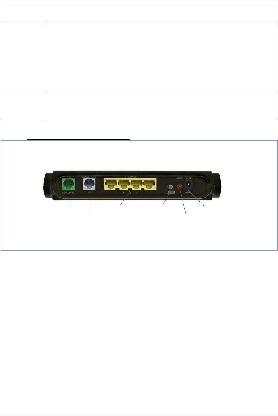
15
Motorola® Gateway NVG510 Rear View
Service
Solid Green = IP connected (The device has a WAN IP address from DHCP or 802.1x
authentication and the broadband connection is
up).
Flashing Green = Attempting PPP connection. Attempting IEEE 802.1X authentication or
attempting to obtain DHCP information.
Red = Device attempted to become IP connected and failed (no DHCP response, no PPPoE
response, 802.1x authentication failed, no IP address from IPCP, etc.). The Red state times
out after two minutes and the Service indicator light returns to the Off state.
Off = The device is not powered or the broadband connection is not present.
Phone 1, 2
Solid Green = The associated VoIP line has been registered with a SIP proxy server.
Flashing Green = Indicates a telephone is off-hook on the associated VoIP line.
Off = VoIP not in use, line not registered or Gateway power off.
LED Action
Factory Reset Switch
DC Power PortWPS PushbuttonEthernet Ports
Phone Port
(use splitter for
2 phones)
DSL Port
Administrator’s Handbook
16
Set up the Motorola Gateway
Refer to your Quickstart Guide for instructions on how to connect your Motorola® gateway to your power source,
PC or local area network, and your Internet access point, whether it is a dedicated DSL outlet or a DSL or cable
modem. Different Motorola® Gateway models are supplied for any of these connections. Be sure to enable
Dynamic Addressing on your PC. Perform the following:
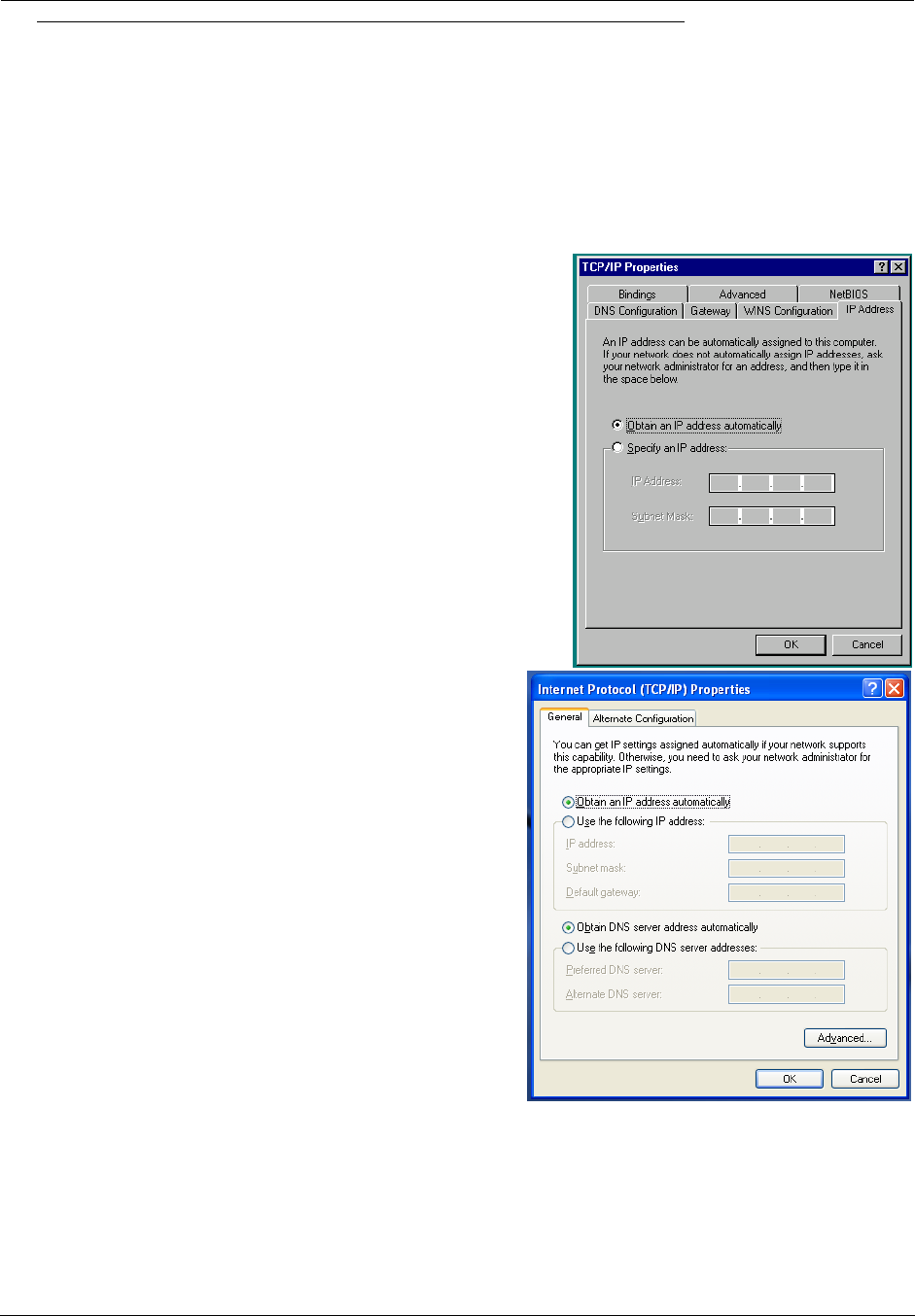
Microsoft Windows:
Step 1. Navigate to the TCP/IP Properties Control Panel.
a. Some Windows versions follow a path like this:
Start menu -> Settings -> Control Panel -> Network (or Network
and Dial-up Connections -> Local Area Connection -> Proper-
ties) -> TCP/IP [your_network_card] or Internet Protocol
[TCP/IP] -> Properties
b. Some Windows versions follow a path like this:
Start menu -> Control Panel -> Network and Internet
Connections -> Network Connections -> Local Area
Connection -> Properties -> Internet Protocol [TCP/IP]
-> Properties
Then go to Step 2.
Step 2. Select Obtain an IP address automatically.
Step 3. Select Obtain DNS server address automatically, if available.
Step 4. Remove any previously configured Gateways, if available.
Step 5. OK the settings. Restart if prompted.
17
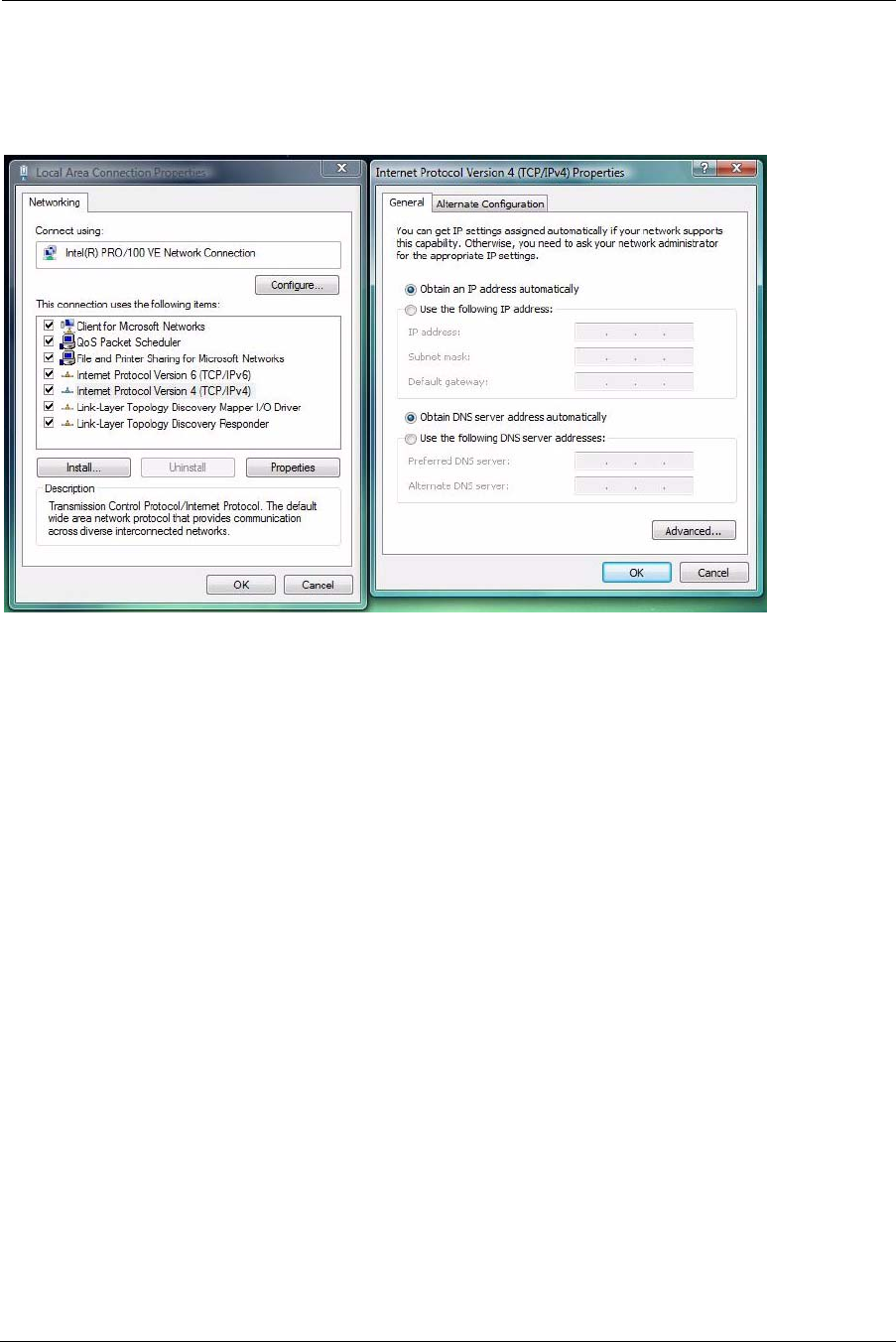
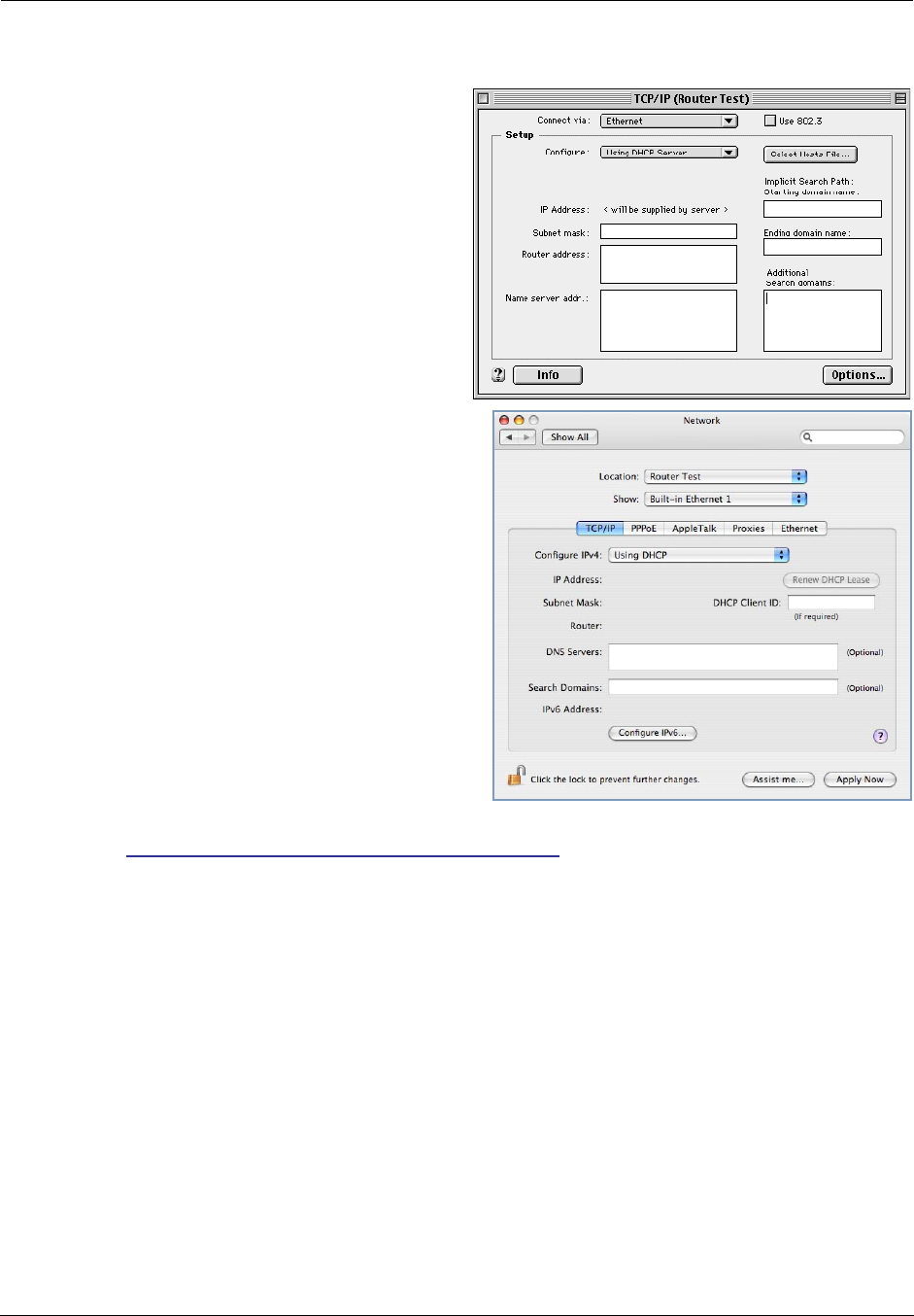
c. Windows Vista and Windows 7 obtain an IP address automatically by default. You may not need to configure it
at all.
To check, open the Networking Control Panel and select Internet Protocol Version 4 (TCP/IPv4). Click the
Properties button.
The Internet Protocol Version 4 (TCP/IPv4) Properties window should appear as shown.
If not, select the radio buttons shown above, and click the OK button.
Administrator’s Handbook
18
Macintosh MacOS 8 or higher or Mac OS X:
Step 1. Access the TCP/IP or Network control panel.
a. MacOS follows a path like this:
Apple Menu -> Control Panels -> TCP/IP Control
Panel
b. Mac OS X follows a path like this:
Apple Menu -> System Preferences -> Network
Then go to Step 2.
Step 2. Select Built-in Ethernet
Step 3. Select Configure Using DHCP
Step 4. Close and Save, if prompted.
Proceed to “Accessing the Web Management Interface” on page 19.
19
Accessing the Web Management Interface
1. Run your Web browser application, such as Firefox or Microsoft Internet Explorer,
from the computer connected to the Motorola® Gateway.
2. Enter http://192.168.1.254 in the Location text box.
The Device Status Page appears.
3. Check to make sure the Broadband and Service LEDs are lit GREEN to verify that
the connection to the Internet is active.
Congratulations! Your installation is complete.
You can now surf to your favorite Web sites by typing an URL in your browser’s location box or by selecting one of
your favorite Internet bookmarks.
21
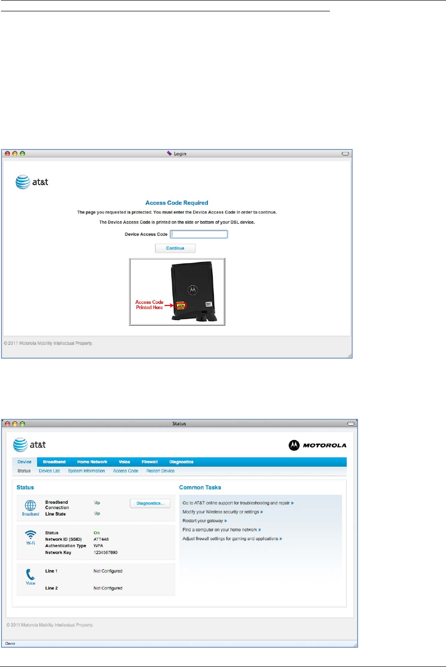
Device Status page
After you have performed the basic Easy Login configuration, any time you log in to your Motorola® Gateway you
will access the Motorola® Gateway Home Page.
You access the Home Page by typing http://192.168.1.254 in your Web browser’s location box.
Device Access Code
You may be required to provide your Device Access Code in order to access the web management configuration
pages. The Device Access Code is unique to your device. It is printed on a label on the side of the Gateway.
Enter your Device Access Code and click the Continue button.
The Device Status Page appears.
Administrator’s Handbook
22
The Device Status displays the following information in the center section:
Some fields may or may not display, depending on your particular setup.
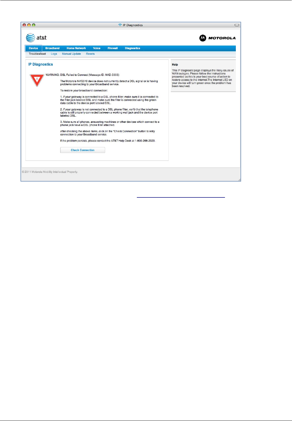
The Diagnostics button will connect you to the Troubleshoot page. See “Diagnostics” on page 61.
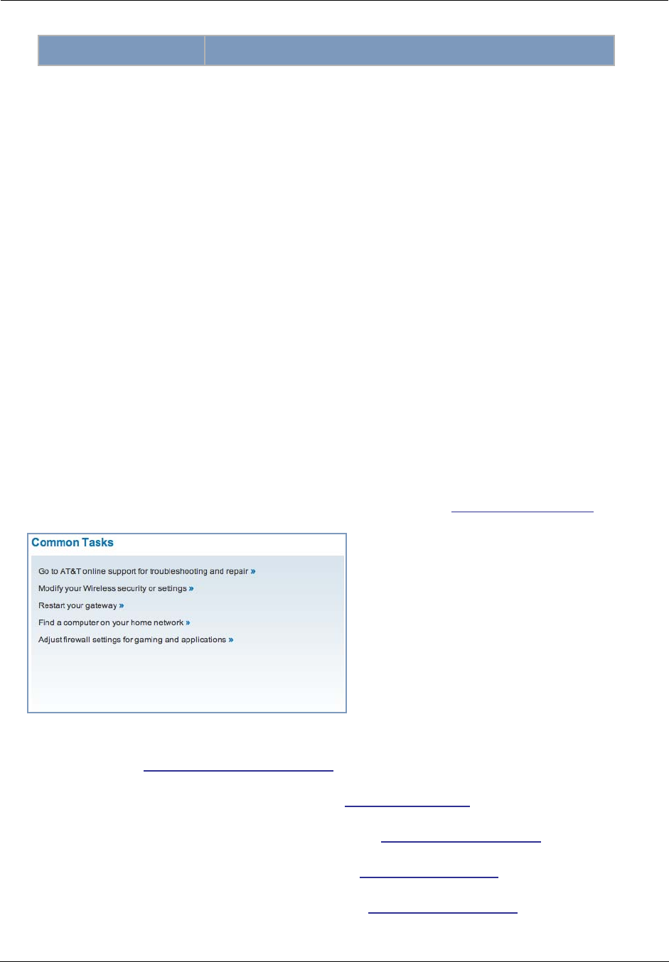
The right-hand frame displays some links to commonly
performed tasks for easy access.
◆Go to AT&T online support for troubleshooting and repair »
This link will connect you to the IP Diagnostics page with help for troubleshooting and the AT&T Help Desk
information. See “IP Diagnostics page” on page 20.
◆Modify your Wireless security or settings »
This link will connect you to the Wireless page. See “Wireless” on page 35.
◆Restart your gateway »
This link will connect you to the Restart Device page. See “Restart Device” on page 27.
◆Find a computer on your home network »
This link will connect you to the Device List page. See “Device List” on page 24.
◆Adjust firewall settings for gaming and applications »
This link will connect you to the NAT/Gaming page. See “NAT/Gaming” on page 53.
Field Description
Broadband
Broadband Connection ‘Waiting for DSL’ is displayed while the Gateway is training. This
should change to ‘Up’ within two minutes.
‘Up’ is displayed when the ADSL line is synched and the PPPoE ses-
sion is established.
‘Down’ indicates inability to establish a connection; possible line fail-
ure.
Line State Line State connection (Internet) is either Up or Down
Wi-Fi
Status Your wireless signal may be ‘On’ or ‘Off’.
Network ID (SSID) This is the name or ID that is displayed to a client scan. The default
SSID for the Gateway is attxxx where xxx is the last 3 digits of the
serial number located on the side of the Gateway.
Authentication Type The type of wireless encryption security in use. May be Disabled,
WPA or WEP, Default Key or Manual.
Network Key Wireless network encryption key in use.
Voice
Line 1 Indication of VoIP or other phone connection.
Line 2 Indication of VoIP or other phone connection.
23
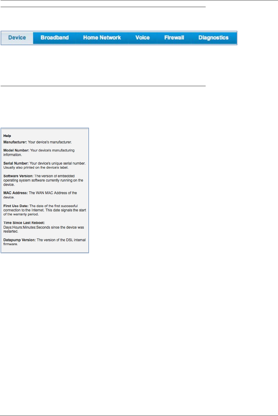
Tab Bar
The tab bar is located at the top of every page, allowing you to move freely about the site.
The tabs reveal a succession of pages that allow you to manage or configure several features of your Gateway.
Each tab is described in its own section.
Help
Help is provided in your Gateway. Help is available in the right hand frame on every page in the Web interface.
Here is an example:
The page shown here is displayed when you are on the
System Information page.
Administrator’s Handbook
24
Links Bar
The links bar at the top of each page allows you to configure different aspects of the features displayed on the
page. For example, on the Home Summary page, the button bar is shown below:
Click the links below to be taken to each section.
◆“Device Status page” on page 21
◆“Device List” on page 24
◆“System Information” on page 25
◆“Access Code” on page 26
◆“Restart Device” on page 27
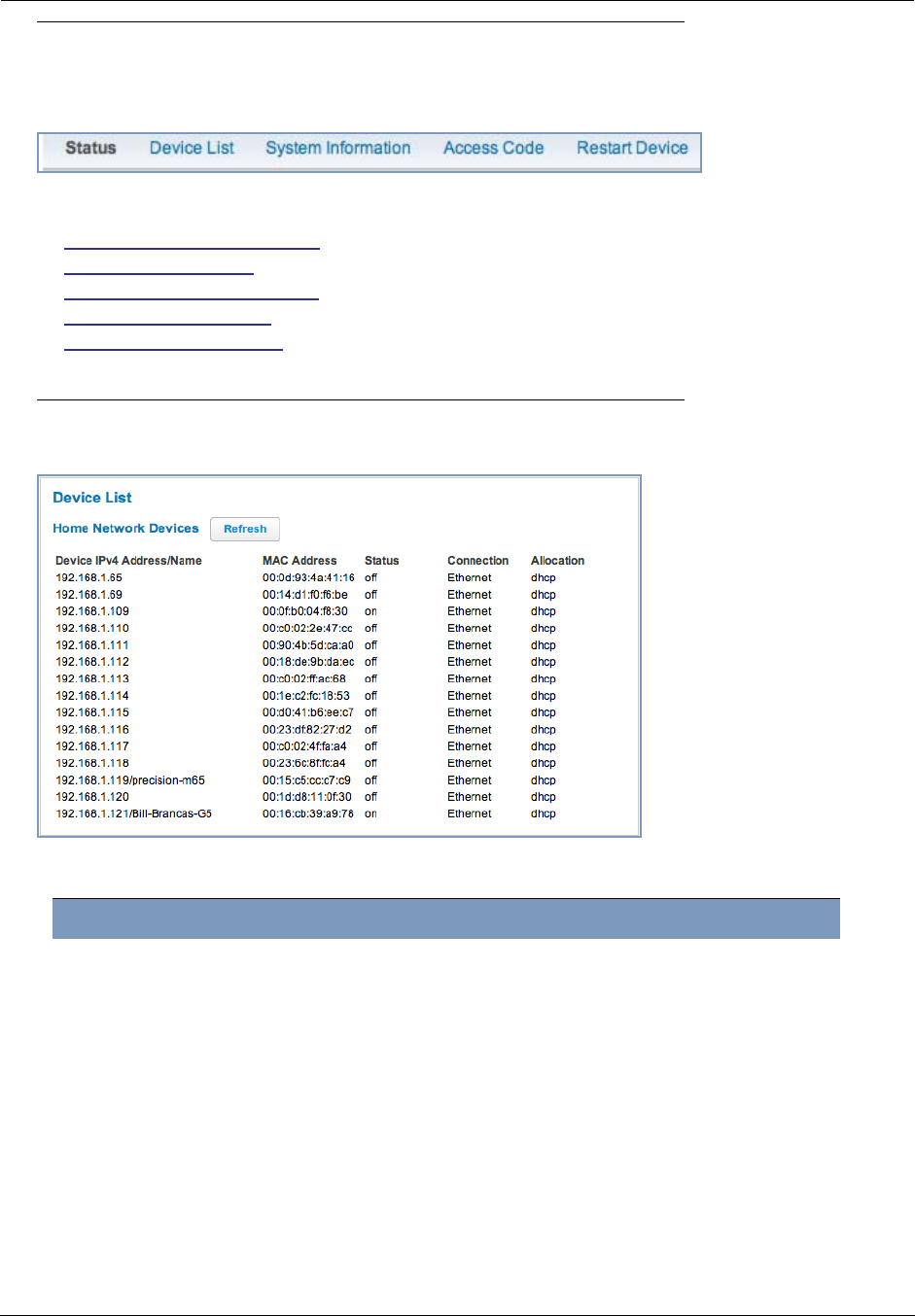
Link: Device List
When you click the Device List link, the Device List page appears.
The page displays the following information:
Click the Refresh button to update the Home Network summary.
Home Network Devices
Home Network Devices Displays the IP Address, Network Name, and MAC Address of
devices connected to this Gateway on your local area network.
Device IPv4 Address Client device’s IP address or device network name.
MAC Address Client device’s unique hardware address.
Status May be off or on.
Connection Type of connection, for example, Ethernet.
Allocation Type of IP address assignment, for example, Static or DHCP.

25
Link: System Information
When you click the System Information link, the System Information page appears.
The page displays the following information:
System Information
Manufacturer This is the manufacturer’s identifier name.
Model Number This is the manufacturer’s model number.
Serial Number This is the unique serial number of your Gateway.
Software Version This is the version number of the current embedded software in your Gateway.
MAC Address Unique hardware address of this Gateway unit.
First Use Date Date and Time when the Gateway is first used. This field changes to the cur-
rent date and time after a reset to factory defaults.
Time Since Last Reboot Elapsed time since last reboot of the Gateway in days:hr:min:sec.
Datapump Version Underlying operating system software datapump version
Legal Disclaimer Clicking the Licenses link displays a listing of software copyright attributions.
Administrator’s Handbook
26
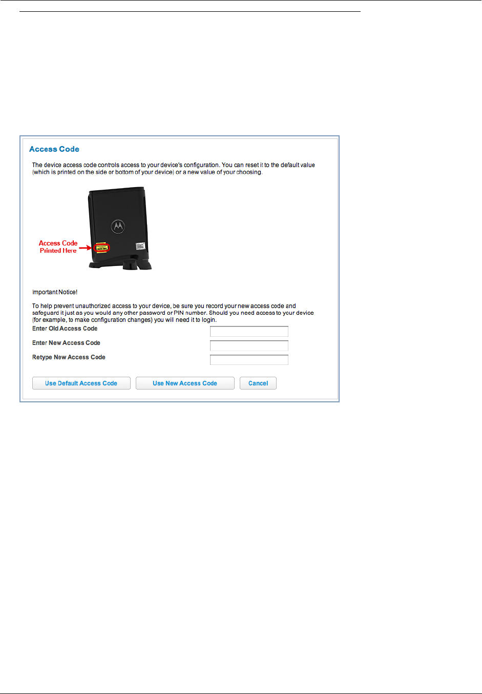
Link: Access Code
Access to your Gateway is controlled through an account named Admin. The default Admin password for your
Gateway is the unique Access Code printed on the label on the side of your Gateway.
As the Admin, you can change this password to a different one of your own choosing up to 32 characters long.
The new password must also include two characters from any these categories: alpha, number, and special char-
acters.
Example: “fru1tfl13s_likeabanana”
Enter your Old Access Code, your New Access Code, and click the Use New Access Code button. The new
Access Code takes effect immediately.
You can always return to the original default password by clicking the Use Default Access Code button.
27
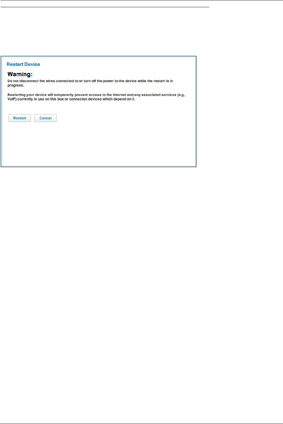
Link: Restart Device
When the Gateway is restarted, it will disconnect all users, initialize all its interfaces, and load the Operating Sys-
tem Software.
When you make configuration changes, you may be required restart for the changes to take effect.
Administrator’s Handbook
28
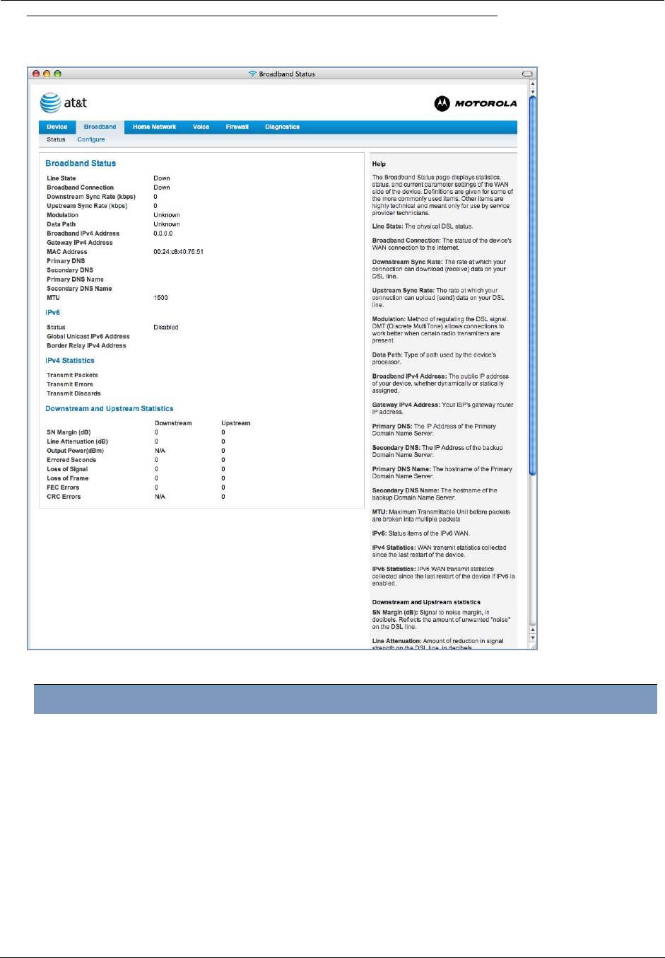
Broadband
When you click the Broadband tab, the Broadband Status page appears.
The Broadband Status page displays information about the Gateway’s WAN connection to the Internet.
Broadband Status
Line State May be Up (connected) or Down (disconnected).
Broadband Connection May be Up (connected) or Down (disconnected).
Downstream Sync Rate This is the rate at which your connection can download (receive) data on your
DSL line, in kilobits per second.
Upstream Sync Rate This is the rate at which your connection can upload (send) data on your DSL
line, in kilobits per second.
Modulation Method of regulating the DSL signal. DMT (Discrete MultiTone) allows connec-
tions to work better when certain radio transmitters are present.
Data Path Type of path used by the device's processor.
Broadband IPv4 Address The public IP address of your device, whether dynamically or statically
assigned.

29
Gateway IPv4 Address Your ISP's gateway router IP address.
MAC Address Your Gateway’s unique hardware address identifier.
Primary DNS The IP Address of the Primary Domain Name Server.
Secondary DNS The IP Address of the backup Domain Name Server, if available.
Primary DNS Name The name of the Primary Domain Name Server.
Secondary DNS Name The name of the backup Domain Name Server, if available.
MTU Maximum Transmittable Unit before packets are broken into multiple packets.
IPv6
Status May be Enabled or Disabled.
Global Unicast IPv6
Address
The public IPv6 address of your device, whether dynamically or statically
assigned.
Border Relay IPv4
Address
The public IPv4 address of your device.
IPv4 Statistics
Transmit Packets IPv4 packets transmitted.
Transmit Errors Errors on IPv4 packets transmitted.
Transmit Discards IPv4 packets dropped.
Downstream and Upstream Statistics
SN Margin (db) Signal to noise margin, in decibels. Reflects the amount of unwanted “noise”
on the DSL line.
Line Attenuation Amount of reduction in signal strength on the DSL line, in decibels.
Output Power (dBm) Measure of power output in decibels (dB) referenced to one milliwatt (mW).
Errored Seconds The number of uncorrected seconds after being down for seven consecutive
seconds.
Loss of Signal The absence of any signal for any reason, such as a disconnected cable or
loss of power.
Loss of Frame A signal is detected but cannot sync with signal caused by mismatched proto-
cols, wrong ISP connection configuration, or faulty cable.
FEC Errors (Forwarded Error Correction errors) Count of received errored packets that
were fixed successfully with out a retry.
CRC Errors Number of times data packets have had to be resent due to errors in transmis-
sion or reception.

Administrator’s Handbook
30
Link: Configure
When you click the Configure link, the Broadband Configure screen appears.
The WAN connection is automatically configured. However, you can adjust the MTU (Maximum Transmittable
Unit) value, if your service provider suggests it. The default 1500 is the maximum value, but some services require
other values. 1492 is common.
If you make any change here, click the Save button.
31
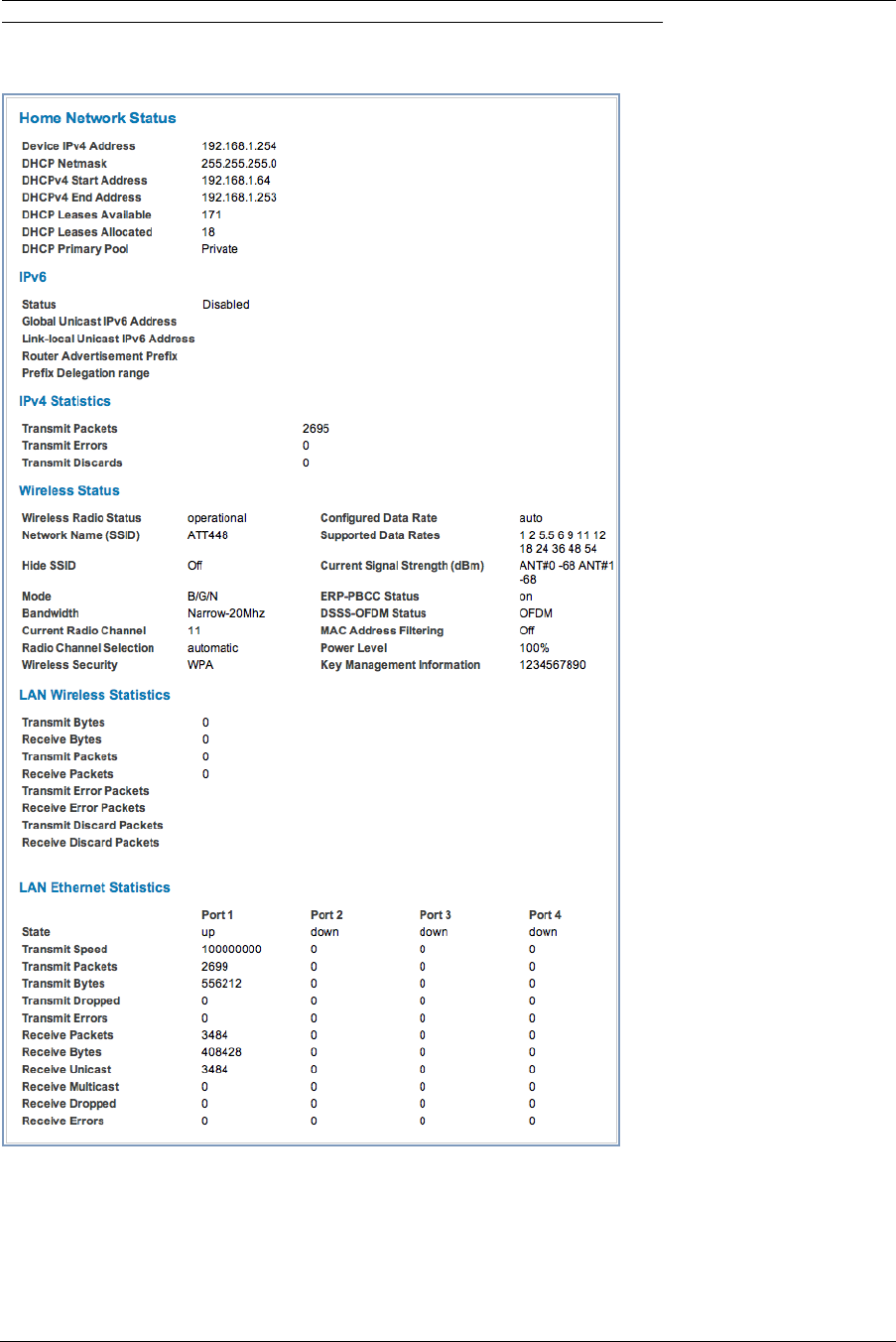
Home Network
When you click the Home Network tab, the Home Network Status page appears.
The Home Network Status page displays information about the Gateway’s local area network.

Administrator’s Handbook
32
Home Network Status
Device IPv4 Address The Gateway’s own IP address on the network.
DHCP Netmask The Gateway’s own netmask on the network.
DHCPv4 Start Address The starting IP address of the DHCP range served by the Gateway.
DHCPv4 End Address The ending IP address of the DHCP range served by the Gateway.
DHCP Leases Available The number of IP addresses of the DHCP range available to be served by the
Gateway.
DHCP Leases Allocated The number of IP addresses of the DHCP range currently being served by the
Gateway.
DHCP Primary Pool Source pool of the IP addresses served by the Gateway, Public or Private.
IPv6
Status May be Enabled or Disabled.
Global Unicast IPv6
Address
The public IPv6 address of your device, whether dynamically or statically
assigned.
Link-local Unicast IPv6
Address
The private IPv6 address of your device, whether dynamically or statically
assigned.
Router Advertisement
Prefix
The IPv6 prefix to include in router advertisements.
Prefix Delegation range The IPv6 prefix range from which prefixes can be delegated to clients by spec-
ifying an IPv6 prefix
IPv4 Statistics
Transmit Packets IPv4 packets transmitted.
Transmit Errors Errors on IPv4 packets transmitted.
Transmit Discards IPv4 packets dropped.
Wireless Status
Wireless Radio Status Indicates whether the Wi-Fi radio is operational or off.
Network Name (SSID) This is the name or ID that is displayed to a client scan. The default SSID for
the Gateway is attxxx where xxx is the last 3 digits of the serial number
located on the side of the Gateway.
Hide SSID May be either On or Off. If On, your SSID will not appear in a client scan.
Mode May be 802.11b only, 802.11g only, 802.11n, or 802.11 b+g+n.
Bandwidth The capacity of the wireless LAN to carry traffic. May be wide or narrow.
Current Radio Channel The radio channel that your Wi-Fi network is broadcasting on.
Radio Channel Selection May be set to automatic or manually selected.
Wireless Security The type of wireless encryption security in use. May be Disabled, WPA-PSK or
WEP, Default Key or Manual.
Configured Data Rate This is the rate that you have configured the wireless driver to use.
Supported Data Rates These are the rates the wireless driver is actually currently advertising and
using. This is a combination of the Configured Rates, plus any run-time limita-
tions that the environment is incurring (for instance, the presence of legacy cli-
ents in the area can limit the offering of higher rates).
Current Signal Strength
(dBm)
This is an average measure of how strong the signals received from clients
are.

33
The links at the top of the Home Network page access a series of pages to allow you to configure and
monitor features of your device. The following sections give brief descriptions of these pages.
◆“Configure” on page 34
◆“Wireless” on page 35
◆“WPS” on page 39
◆“MAC Filtering” on page 40
◆“Subnets & DHCP” on page 41
ERP-PBCC Status This tells whether or not the Gateway is honoring legacy 802.11b compatibility
mode.
DSSS-OFDM Status This is the wireless modulation in use. DSS if in b-only mode, OFDM other-
wise.
MAC Address Filtering May be either On or Off. If On, you can accept or block client devices from
your WLAN based on their MAC address.
Power Level May be adjusted up to 100%, lower if multiple wireless access points are in
use, and might interfere with each other.
Key Management Infor-
mation
Shows the information of the security encryption key in use.
LAN Wireless Statistics
Bytes Transmitted Number of bytes transmitted on the Wi-Fi network.
Bytes Received Number of bytes received on the Wi-Fi network.
Packets Transmitted Number of packets transmitted on the Wi-Fi network.
Packets Received Number of packets received on the Wi-Fi network.
Error Packets Transmitted This is the number of errors on packets transmitted on the Wi-Fi network.
Error Packets Received This is the number of errors on packets received on the Wi-Fi network.
Discard Packets Transmit-
ted
This is the number of packets transmitted on the Wi-Fi network that were
dropped.
Discard Packets Received This is the number of packets received on the Wi-Fi network that were
dropped.
LAN Ethernet Statistics
State up or down
Transmit Speed This is the maximum speed of which the port is capable.
Transmit Packets This is the number of packets sent out from the port.
Transmit Bytes This is the number of bytes sent out from the port.
Transmit Dropped This is the number of packets sent out from the port that were dropped.
Transmit Errors This is the number of errors on packets sent out from the port.
Receive Packets This is the number of packets received on the port.
Receive Bytes This is the number of bytes received on the port.
Receive Unicast This is the number of unicast packets received on the port.
Receive Multicast This is the number of multicast packets received on the port.
Receive Dropped This is the number of packets received on the port that were dropped.
Receive Errors This is the number of errors on packets received on the port.
Administrator’s Handbook
34
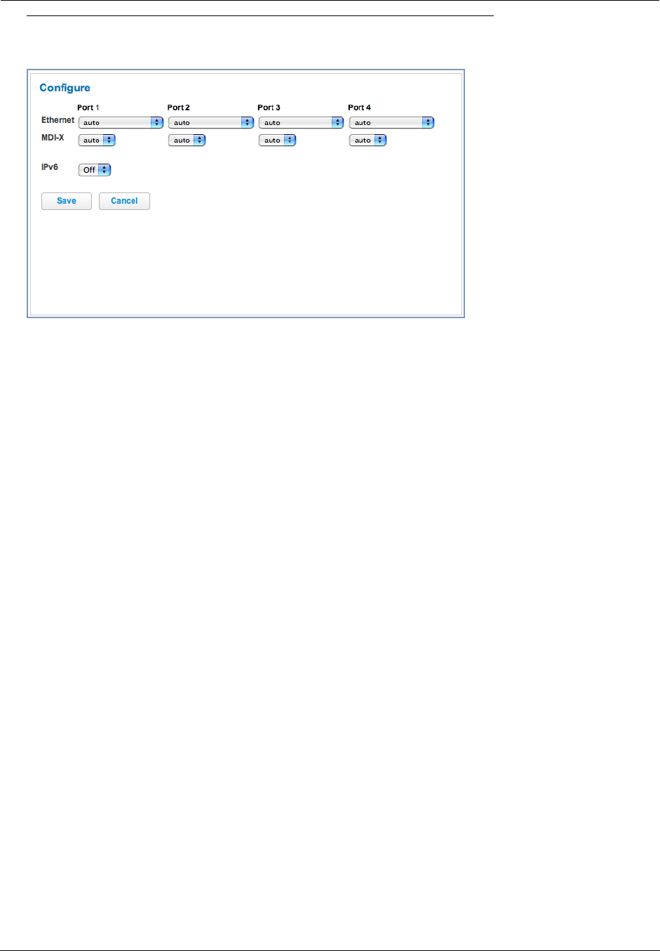
Link: Configure
When you click the Configure link, the Configure page for the Ethernet LAN appears.
For each Ethernet Port, 1 through 4, you can select:
◆Ethernet – auto (the default self-sensing rate), 10M full- or half-duplex, 100M full- or half-duplex, or 1G full- or
half-duplex.
◆MDI-X – auto (the default self-sensing crossover setting), off, or on.
You can also enable or disable IPv6 if your LAN devices support or require it. Select On or Off from the pull-down
menu.
Click the Save button.
35
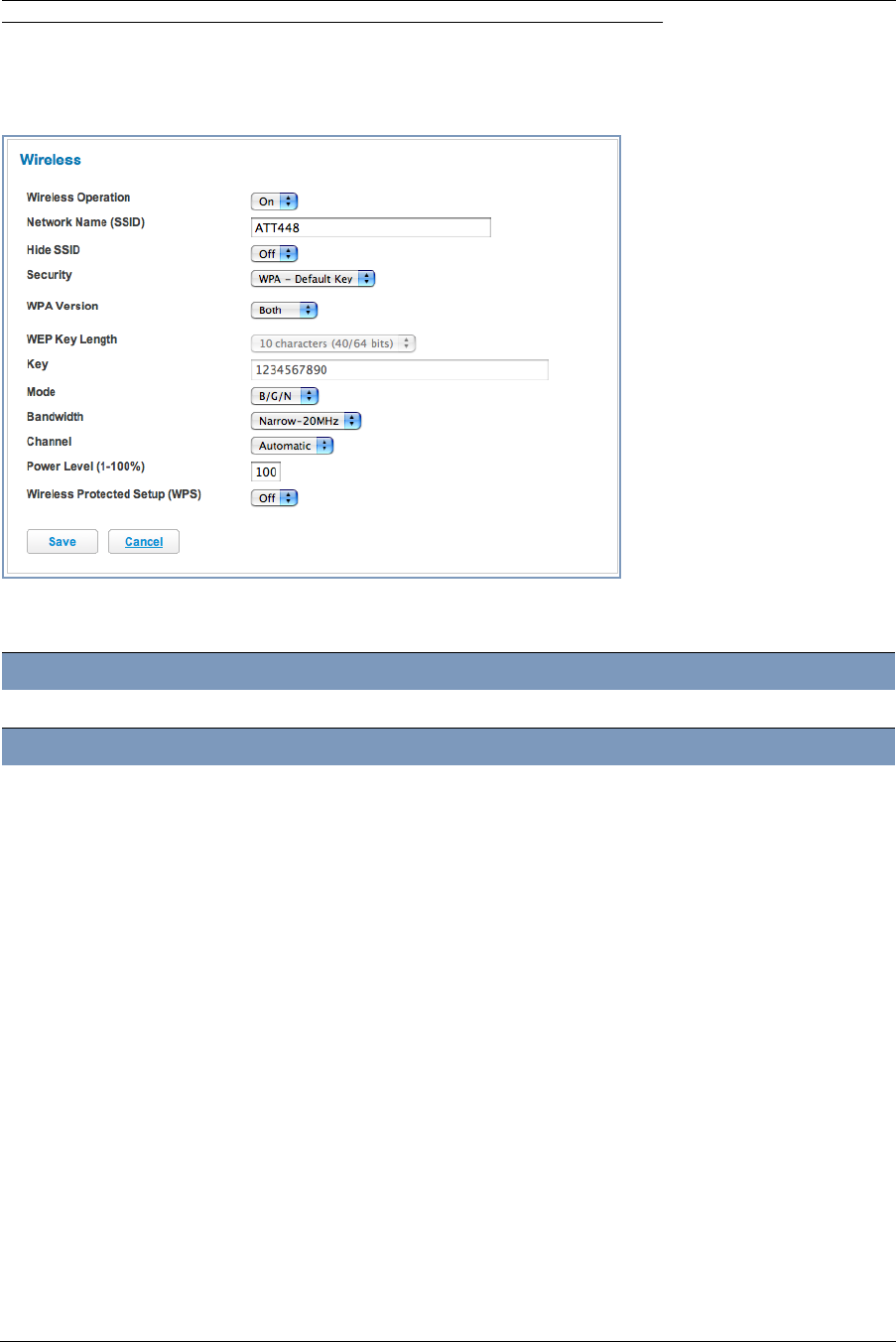
Link: Wireless
When you click the Wireless link the Wireless page appears. The Wireless page displays the status of your
Wireless LAN elements.
The Wireless page’s center section contains a summary of the Wireless Access Point’s configuration
settings and operational status.
◆The Wireless Operation function is automatically enabled by default. If you uncheck the checkbox, the Wire-
less Options are disabled, and the Wireless Access Point will not provide or broadcast its wireless LAN ser-
vices.
Summary Information
Field Status and/or Description
General Information
Wireless Operation May be either
On
or
Off.
Network Name (SSID) This is the name or ID that is displayed to a client scan. The default SSID for the
Gateway is
attxxx
where
xxx
is the last 3 digits of the serial number located on
the side of the gateway.
Hide SSID May be either
Enabled
or
Disabled
. If Enabled, your SSID will not appear in a
client scan.
Security The type of wireless encryption security in use. May be
OFF-No Privacy
,
WPA-
PSK
or
WEP
,
Default
Key
or
Manual
.
WPA Version If WPA is selected, may be Both, WPA-1, or WPA-2,.
WEP Key Length May be 10 characters for 40/64-bit, or 26 characters for 128-bit WP encryption.
Key Here you can enter a manual encryption key.
Mode May be 802.11b only, 802.11g only, 802.11n, or 802.11 b+g+n.
Bandwidth The capacity of the wireless LAN to carry traffic. May be
wide
or
narrow
.
Channel The radio channel that your Wi-Fi network is broadcasting on.
Power Level May be adjusted up to 100%, lower if multiple wireless access points are in use,
and might interfere with each other.
Wireless Protected Setup
(WPS)
May be either
On
or
Off.

Administrator’s Handbook
36
◆Network Name (SSID) – preset to a number unique to your unit. You can either leave it as is, or change it by
entering a freeform name of up to 32 characters, for example “Hercule’s Wireless LAN”. On client PCs’ soft-
ware, this might also be called the Network Name. The Wireless ID is used to identify this particular wireless
LAN. Depending on their operating system or client wireless card, users must either:
• select from a list of available wireless LANs that appear in a scanned list on their client
• or enter this name on their clients in order to join this wireless LAN.
◆Hide SSID – If enabled, this mode hides the wireless network from the scanning features of wireless client
computers. Unless both the wireless clients and the Gateway share the same Network Name (SSID) in hidden
mode, the Gateway’s wireless LAN will not appear as an available network when scanned for by wireless-
enabled computers. Members of the hidden WLAN must log onto the Gateway’s wireless network with the
identical SSID as that configured in the Gateway.
Closed System mode is an ideal way to increase wireless security and to prevent casual detection by
unwanted neighbors, office users, or malicious users such as hackers. If you do not enable Hide SSID, it is
more convenient, but potentially less secure, for clients to access your WLAN by scanning available
access points. You must decide based on your own network requirements.
◆Security, WPA Version, WEP Key Length, Key – see “Wireless Security” on page 37.
◆Mode – The pull-down menu allows you to select and lock the Gateway into the wireless transmission mode
you want: B/G/N, B-only, B/G, G-only, or N-only.
For compatibility with clients using 802.11b (up to 11 Mbps transmission), 802.11g (up to 20+ Mbps), 802.11a
(up to 54 Mbit/s using the 5 GHz band), or 802.11n (from 54 Mbit/s to 600 Mbit/s with the use of four spatial
streams at a channel width of 40 MHz), select B/G/N. To limit your wireless LAN to one mode or the other,
select G-only, N-only, or B-only, or some combination that applies to your setup.
☛ NOTE:
If you choose to limit the operating mode to 802.11b or 802.11g only, clients using the mode you
excluded will not be able to connect.
◆Bandwidth – May only be selected if mode is some combination of 802.11n (from 54 Mbit/s to 600 Mbit/s
with the use of four spatial streams at a channel width of 40 MHz). Measure of the width of a range of frequen-
cies, in megahertz.
◆Channel (1 through 11, for North America) on which the network will broadcast. This is a frequency range
within the 2.4Ghz band. Channel selection depends on government regulated radio frequencies that vary from
region to region. Channel selection can have a significant impact on performance, depending on other wireless
activity close to this Wireless Access Point. You need not select a channel at any of the computers on your
wireless network. They will automatically scan available channels seeking a Gateway broadcasting on the
SSID for which they are configured.
The Automatic setting allows the Wireless Access Point to determine the best channel to broadcast automati-
cally.
◆Wireless Power Level – Sets the wireless transmit power, scaling down the Wireless Access Point’s wireless
transmit coverage by lowering its radio power output. Default is 100% power. Transmit power settings are use-
ful in large venues with multiple wireless routers where you want to reuse channels. Since there are only three
non-overlapping channels in the 802.11 spectrum, it helps to size the Wireless Access Point’s cell to match the
location. This allows you to install a router to cover a small “hole” without conflicting with other routers nearby.
◆Wireless Protected Setup (WPS) is a not a new security protocol. It is simply an easier way to use existing
protocols to provide greater security for your wireless network connections.
By default, Privacy is set to Wireless Protected Access (WPA-PSK). WPS allows you to automatically
generate a new strong WPA key for your Gateway and any client devices on your wireless network.
☛ Note:
Not all client wireless devices support WPS. Refer to their documentation.
37
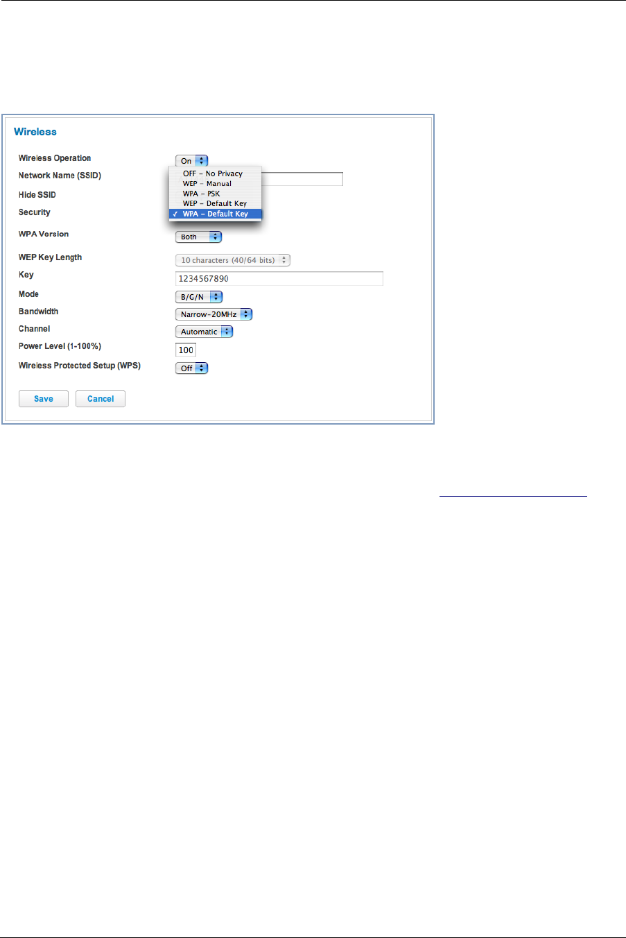
Wireless Security
By default, Wireless Security is set to
WPA-PSK
with a pre-defined WPA-Default Key (Wireless Protected Access
Pre-Shared Key).
Other options are available from the Security pull-down menu:
◆WEP - Manual: WEP Security is a Privacy option that is based on encryption between the Router and any PCs
(“clients”) you have with wireless cards. If you are not using WPA-PSK Privacy, you can use WEP encryption
instead. For this encryption to work, both your Wireless Access Point and each client must share the same
Wireless ID (SSID), and both must be using the same encryption keys. See “WEP-Manual” on page 37.
◆WPA-PSK: allows you to enter your own key, the most secure option for your wireless network. The key can
be between 8 and 63 characters, but for best security it should be at least 20 characters.
If you select WPA-PSK as your privacy setting, the WPA Version pull-down menu allows you to select the WPA
version(s) that will be required for client connections. Choices are:
Both, for maximum interoperability,
WPA-1, for backward compatibility,
WPA-2, for maximum security.
All clients must support the version(s) selected in order to successfully connect.
Be sure that your Wi-Fi client adapter supports this option. Not all Wi-Fi clients support WPA-PSK.
◆OFF - No Privacy: This mode disables privacy on your network, allowing any wireless users to connect to your
wireless LAN. Use this option if you are using alternative security measures such as VPN tunnels, or if your
network is for public use.
Click the Save button.
WEP-Manual
You can provide a level of data security by enabling WEP (Wired Equivalent Privacy) for encryption of net-
work data. You can enable 40- or 128-bit WEP Encr yption (depending on the capability of your client
wireless card) for IP traffic on your LAN.
WEP - Manual allows you to enter your own encryption keys manually. This is a difficult process, but
only needs to be done once. Avoid the temptation to enter all the same characters.

Administrator’s Handbook
38
Key Length: The pull-down menu selects the length of each encryption key. The longer the key, the
stronger the encryption and the more difficult it is to break the encryption.
Key: You enter a key using hexadecimal digits. For 40/64-bit encryption, you need ten digits; 26 digits
for 128-bit WEP. Hexadecimal characters are 0 – 9, and a – f.
Examples:
◆ 40 bits: 02468ACE02
◆ 128 bits: 0123456789ABCDEF0123456789
Any WEP-enabled client must have an identical key of the same length as the Router, in order to suc-
cessfully receive and decrypt the traffic. Similarly, the client also has a ‘default’ key that it uses to
encrypt its transmissions. In order for the Router to receive the client’s data, it must likewise have the
identical key of the same length.
Click the click Save button.
39
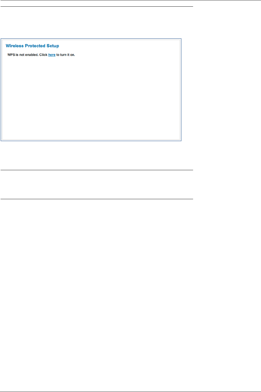
Link: WPS
Wireless Protected Setup (WPS) is a not a new security protocol. It is simply an easier way to use existing pro-
tocols to provide greater security for your wireless network connections.
By default, Privacy is set to Wireless Protected Access (WPA-PSK). WPS allows you to automatically generate a
new strong WPA key for your Gateway and any client devices on your wireless network.
☛ Note:
Not all client wireless devices support WPS. Refer to their documentation.
Adding wireless clients to your network is easier using Wireless Protected Setup (WPS). Before you begin, be
sure WPS is enabled on your device. WPS clients will be "auto-configured" by pushbutton or PIN-entry. Older,
non-WPS clients can still be added to the network by configuring them the standard way with WPA-PSK or WEP.
The client machine(s) to be added should be powered on and their wireless cards operational. Follow any instruc-
tions that came with your wireless client devices.
Click the here link to proceed.
Administrator’s Handbook
40
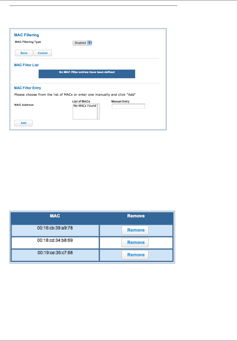
Link: MAC Filtering
When you click the MAC Filtering link the MAC Filtering page appears.
MAC Filtering allows you to specify which client PCs are allowed to join the wireless LAN by unique hardware
(MAC) address.
◆To enable this feature, select Blacklist or Whitelist from the MAC Filtering Type menu. Blacklist means that
only MAC addresses you specify will be denied access; Whitelist means that only MAC addresses you specify
will be allowed access.
◆You add wireless clients that you want to Whitelist or Blacklist for your wireless LAN by selecting them from the
List of MACs or by entering the MAC addresses in the Manual Entry field provided.
◆Click the Add button.
Your entries will be added to a list of clients that will be either authorized (Whitelisted) or disallowed
(Blacklisted) depending on your selection.
◆Click the Save button.
You can Add or Remove any of your entries later by returning to this page.
41
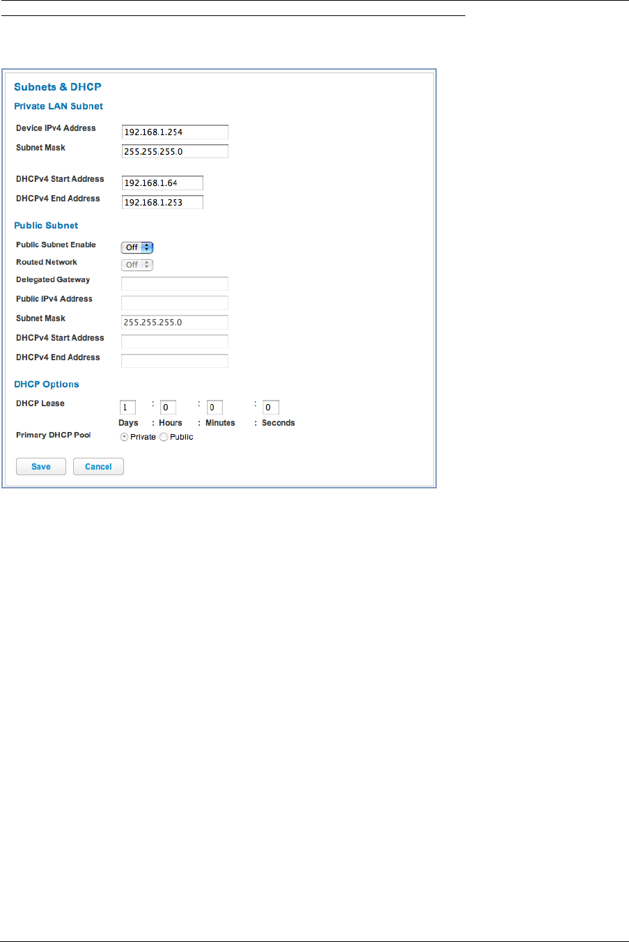
Link: Subnets & DHCP
When you click the Subnets & DHCP link, the Subnets & DHCP page appears.
The Server configuration determines the functionality of your DHCP Settings. This functionality enables the Gate-
way to assign your LAN computer(s) a “private” IP address and other parameters that allow network communica-
tion. This feature simplifies network administration because the Gateway maintains a list of IP address
assignments. Additional computers can be added to your LAN without the hassle of configuring an IP address.
This is the default mode for your Gateway.
Private LAN Subnet
◆Device IP Address: The IP address of your Gateway as seen from the LAN
◆Subnet Mask: Subnet mask of your LAN
◆DHCP Start Address: First IP address in the range being served to your LAN by the Gateway's DHCP server
◆DHCP End Address: Last IP address in the range being served to your LAN by the Gateway's DHCP server
Public Subnet
◆Public Subnet Enable: If you select On from the pull-down menu, you can enable a second subnet to distrib-
ute public addresses to DHCP clients.
◆Routed Network: If Public Subnet Enable is checked, this selection permits you to specify Gateway Selec-
tion by the Gateway Router IP Address or its Router Name.
◆Delegated Gateway: The IP address for a router set up behind this Gateway, if one is used.
◆Public IPv4 Address: The IP address of your Gateway as seen from the WAN
◆Subnet Mask: Public subnet mask
◆DHCPv4 Start Address: First IP address in the range being served from a DHCP public pool.
◆DHCPv4 End Address: Last IP address in the range being served from a DHCP public pool.

Administrator’s Handbook
42
DHCP Options
◆DHCP Lease Time: Specifies the default length for DHCP leases issued by the Router. Enter lease time in
dd:hh:mm:ss (days/hours/minutes/seconds) format.
◆Primary DHCP Pool: Choose the source of the DHCP pool IP address assignment by selecting either the Pri-
vate (local to your LAN) or Public (assigned remotely) radio button.
If you make any changes here, click the Save button, and if prompted, restart the Gateway.
43
Voice
If you click the Voice ink, the Voice page appears.
Voice-over-IP (VoIP) refers to the ability to make voice telephone calls over the Internet. This differs from tradi-
tional phone calls that use the Public Switched Telephone Network (PSTN). VoIP calls use an Internet protocol,
Session Initiation Protocol (SIP), to transmit sound over a network or the Internet in the form of data packets.
◆The Voice page displays information about your VoIP phone lines, if configured. Your Gateway supports two
phones, Line 1 and Line 2.
◆If either one or both are registered with a SIP server by your service provider or not registered, the Voice page
will display their Registration Status.
The links at the top of the Voice page access a series of pages to allow you to configure and monitor
features of your device. The following sections give brief descriptions of these pages.
◆“Line Details” on page 44
◆“Call Statistics” on page 45
Administrator’s Handbook
44
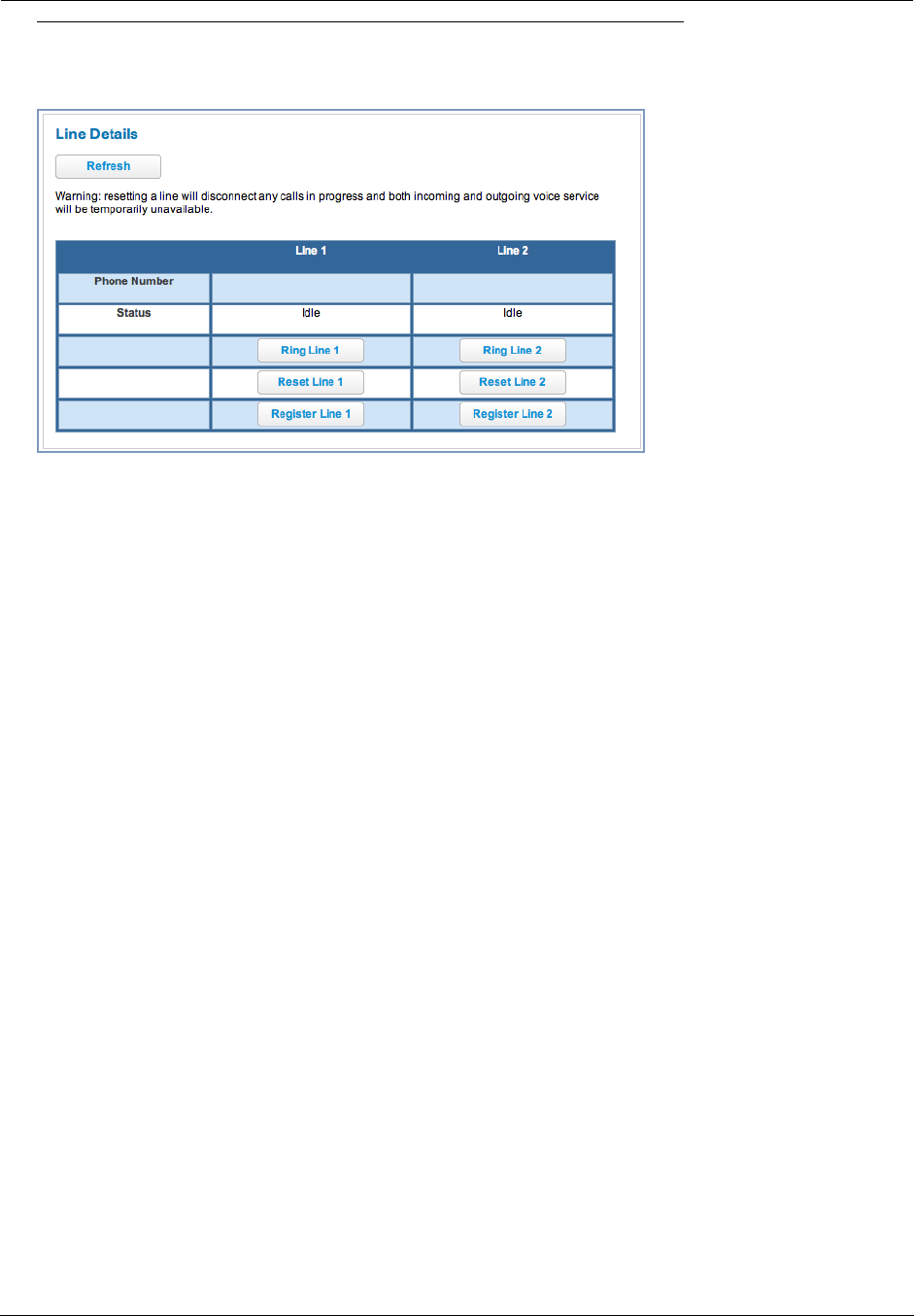
Link: Line Details
When you click the Line Details link, the Line Details page appears.
◆If your service provider has enabled your VoIP phone lines, you can register them by clicking the Register
Line 1 or Register Line 2 button(s).
◆To test if the lines are enabled, click the Ring Line 1 or Ring Line 2 button(s). If enabled and registered, the
respective phone will ring until you click the Stop Ring Line 1 or Stop Ring Line 2 buttons.
◆To update the display, click the Refresh button.
45
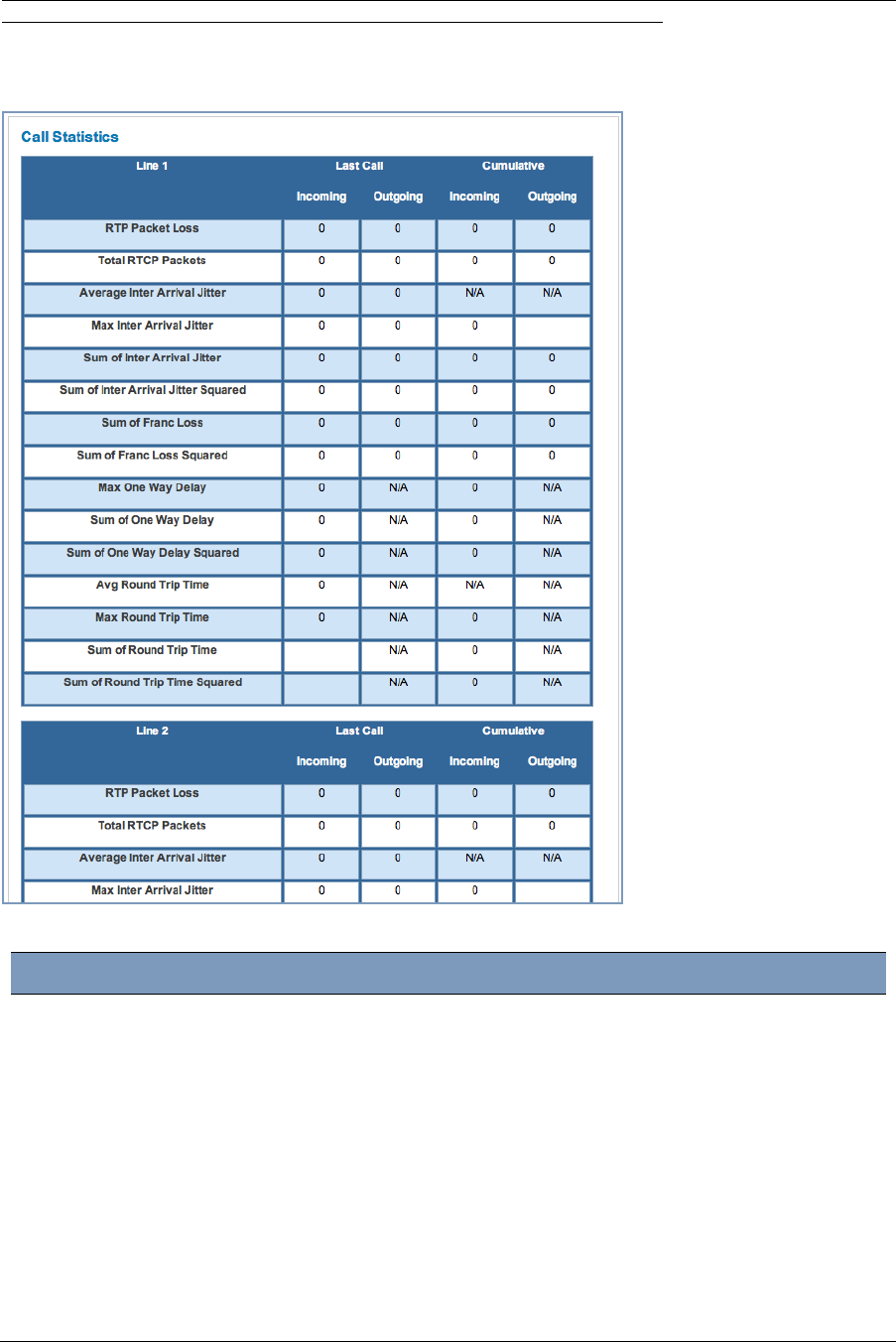
Link: Call Statistics
When you click Call Statistics, the Call Statistics page appears.
For Line 1 and Line 2:, the two available phone lines, the Call Statistics page displays the following information:
Call Statistics - Line 1 and Line 2
Last Call/Cumulative – Incomin/Outgoing
RTP Packet Loss Real-time Transport Protocol packets dropped
Total RTCP Packets Total Real-time Transport Control Protocol packets
Average Inter Arrival Jitter This is calculated continuously as each data packet is received and averaged.
Max Inter Arrival Jitter This is the maximum value recorded as each data packet is received.
Sum of Inter Arrival Jitter This is calculated continuously as each data packet is received and totalled.
Sum of Inter Arrival Jitter
Squared
This is calculated continuously as each data packet is received and the total is
squared.

Administrator’s Handbook
46
Sum of Franc Loss Fraction Lost: The fraction of RTP data packets lost since the previous SR or
RR packet was sent. This fraction is defined to be the number of packets lost
divided by the number of packets expected. This will be calculated on every
RTCP SR packet. Sum of the fraction lost is calculated with all the RTCP pack-
ets.
Sum of Franc Loss
Squared
Fraction lost is squared with every RTCP SR or RR packet. Sum of all this will
give the Sum of Franc Loss Squared.
Max One Way Delay One Way Delay will be calculated on every RTCP SR or RR packet. This value
is ( systime - lsr - dslr) / 2
lsr means last SR timestamp
dslr means delay since last SR.
Sum of One Way Delay The sum of all the one way delays calculated on every RTCP packet is dis-
played as Sum of One Way Delay.
Sum of One Way Delay
Squared
One Way Delay is squared with every RTCP SR or RR packet. Sum of all this
will give the Sum of One Way Delay Squared.
Avg Round Trip Time Average time from this local source to destination address and back again for
all logged calls
Max Round Trip Time Maximum amount of time from this local source to destination address and
back again for all logged calls
Sum of Round Trip Time Sum of time from this local source to destination address and back again for all
logged calls
Sum of Round Trip Time
Squared
Sum squared of time from this local source to destination address and back
again for all logged calls
47
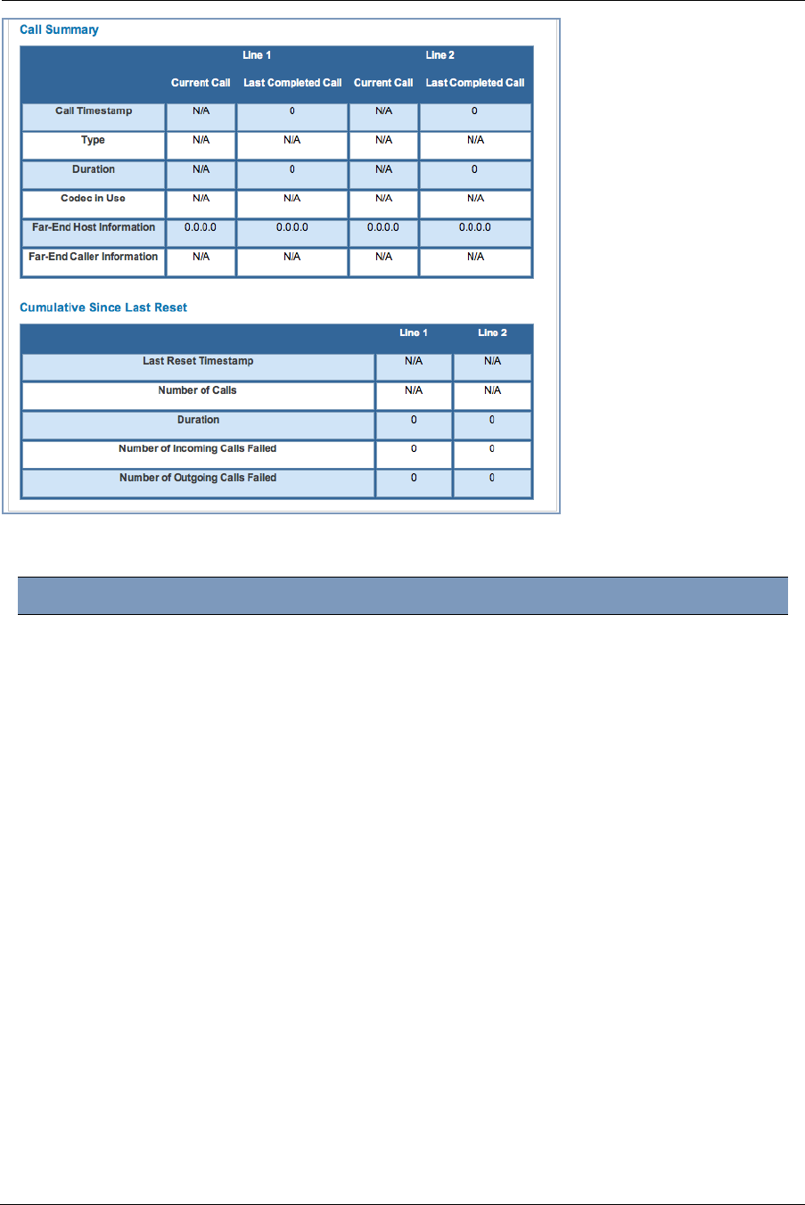
For Line 1 and Line 2:, the two available phone lines, the Call Summary section displays the following informa-
tion:
Call Summary - Line 1 and Line 2
Current Call/Last Completed Call
Call Timestamp Date and Time of the current call
Type May be Incoming or Outgoing
Duration Length of time of call connection
Codec in Use Audio codec used for decoding the call packet traffic.
Far-End Host Information SIP server IP information: IP address and port number
Far-End Caller Information Caller ID information, if available
Cumulative Since Last Reset
Last Reset Timestamp Date and Time of the last call
Number of Calls Total number of calls for each VoIP line
Duration Time since the last call
Number of Incoming Calls Failed Number of Incoming calls that fail to connect
Number of Outgoing Calls Failed Number of Outgoing calls that fail to connect
Administrator’s Handbook
48
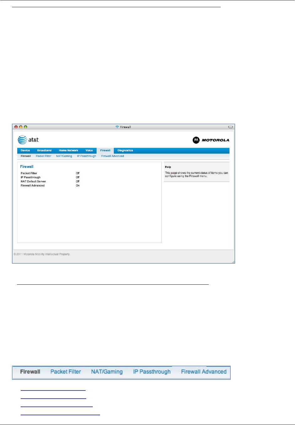
Firewall
When you click the Firewall tab, the Firewall Status page appears. The Firewall page displays the status of your
system firewall elements.
All computer operating systems are vulnerable to attack from outside sources, typically at the operating system or
Internet Protocol (IP) layers. Stateful Inspection firewalls intercept and analyze incoming data packets to deter-
mine whether they should be admitted to your private LAN, based on multiple criteria, or blocked. Stateful inspec-
tion improves security by tracking data packets over a period of time, examining incoming and outgoing packets.
Outgoing packets that request specific types of incoming packets are tracked; only those incoming packets consti-
tuting a proper response are allowed through the firewall.
Stateful inspection is a security feature that prevents unsolicited inbound access when NAT is disabled. You can
configure UDP and TCP “no-activity” periods that will also apply to NAT time-outs if stateful inspection is enabled
on the interface. Stateful Inspection parameters are active on a WAN interface only if enabled on your system.
Stateful inspection can be enabled on a WAN interface whether NAT is enabled or not.
The center section displays the following:
The links at the top of the Firewall page access a series of pages to allow you to configure security features of
your device. The following sections give brief descriptions of these pages.
◆“Packet Filter” on page 49
◆“NAT/Gaming” on page 53
◆“IP Passthrough” on page 58
◆“Firewall Advanced” on page 60
Packet Filter May be On or Off
IP Passthrough May be On or Off
NAT Default Server May be On or Off
Firewall Advanced May be On or Off
49
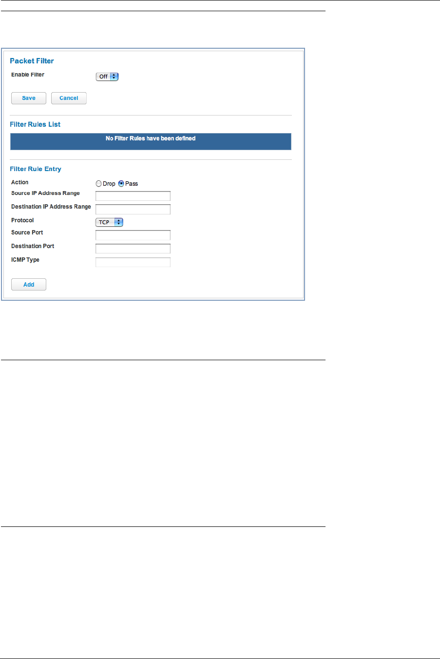
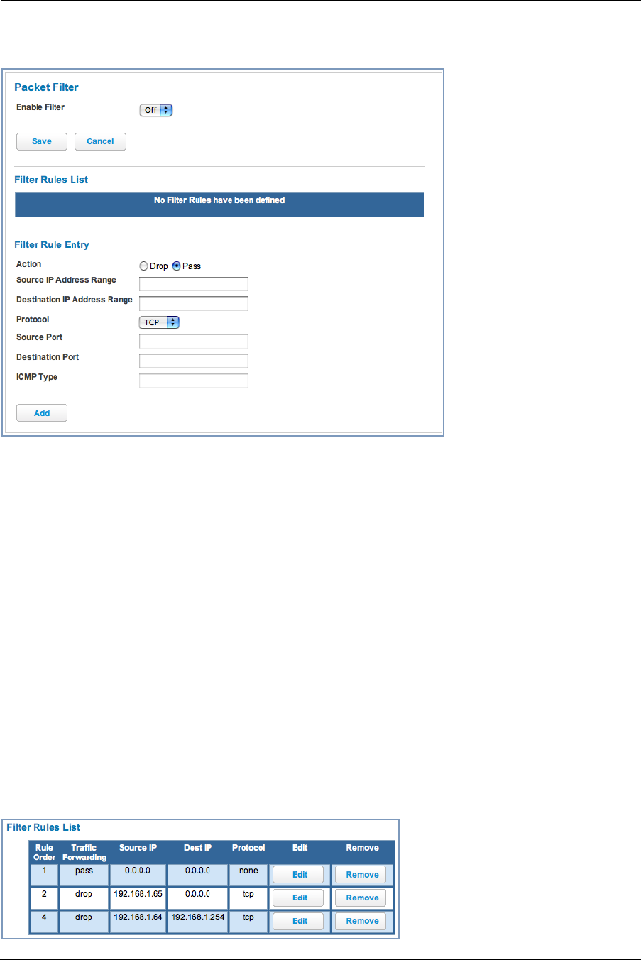
Link: Packet Filter
When you click the Packet Filter link the Packet Filter screen appears.
Security should be a high priority for anyone administering a network connected to the Internet. Using packet fil-
ters to control network communications can greatly improve your network’s security. The Packet Filter engine
allows creation of a maximum of eight Filtersets. Each Filterset can have up to eight rules configured.
☛ WARNING:
Before attempting to configure filters and filtersets, please read and understand this entire section
thoroughly. The Motorola Gateway incorporating NAT has advanced security features built in.
Improperly adding filters and filtersets increases the possibility of loss of communication with the
Gateway and the Internet. Never attempt to configure filters unless you are local to the Gateway.
Although using filtersets can enhance network security, there are disadvantages:
• Filters are complex. Combining them in filtersets introduces subtle interactions, increasing the like-
lihood of implementation errors.
• Enabling a large number of filters can have a negative impact on performance. Processing of pack-
ets will take longer if they have to go through many checkpoints in addition to NAT.
• Too much reliance on packet filters can cause too little reliance on other security methods. Filter-
sets are not a substitute for password protection, effective safeguarding of passwords, and general
awareness of how your network may be vulnerable.
Motorola’s packet filters are designed to provide security for the Internet connections made to and from your net-
work. You can customize the Gateway’s filtersets for a variety of packet filtering applications. Typically, you use fil-
ters to selectively admit or refuse TCP/IP connections from certain remote networks and specific hosts. You will
also use filters to screen particular types of connections. This is commonly called firewalling your network.
Before creating filtersets, you should read the next few sections to learn more about how these powerful security
tools work.

Administrator’s Handbook
50
Parts of a filter
A filter consists of criteria based on packet attributes. A typical filter can match a packet on any one of the follow-
ing attributes:
◆The source IP address (where the packet was sent from)
◆The destination IP address (where the packet is going)
◆The type of higher-layer Internet protocol the packet is carrying, such as TCP or UDP
Other filter attributes
There are three other attributes to each filter:
◆The filter’s order (i.e., priority) in the filterset
◆Whether the filter is currently active
◆Whether the filter is set to forward packets or to block (discard) packets
Design guidelines
Careful thought must go into designing a new filterset. You should consider the following guidelines:
◆Be sure the filterset’s overall purpose is clear from the beginning. A vague purpose can lead to a faulty set, and
that can actually make your network less secure.
◆Be sure each individual filter’s purpose is clear.
◆Determine how filter priority will affect the set’s actions. Test the set (on paper) by determining how the filters
would respond to a number of different hypothetical packets.
◆Consider the combined effect of the filters. If every filter in a set fails to match on a particular packet, the
packet is:
• Forwarded if all the filters are configured to discard (not forward)
• Discarded if all the filters are configured to forward
• Discarded if the set contains a combination of forward and discard filters
An approach to using filters
The ultimate goal of network security is to prevent unauthorized access to the network without compromising
authorized access. Using filtersets is part of reaching that goal.
Each filterset you design will be based on one of the following approaches:
◆That which is not expressly prohibited is permitted.
◆That which is not expressly permitted is prohibited.
It is strongly recommended that you take the latter, and safer, approach to all of your filterset designs.
51
Working with Packet Filters
To work with filters, begin by accessing the Packet Filter pages.
Packet Filter
◆Enable Filter – Select On from the pull-down menu to enable this filter rule.
Filter Rule Entry
◆Action – Select either the drop or pass radio buttons:
• drop: If you select drop, the specified packets will be blocked.
• pass: If you select pass, the specified packets will be forwarded.
◆Enter the Source IP Address this filter will match on.
◆Enter the Destination IP Address this filter will match on.
◆Select Protocol from the pull-down menu: ICMP, TCP, UDP, or None to specify any another IP transport proto-
col.
◆Enter the Source Port this filter will match on.
◆Enter the Destination Port this filter will match on.
◆If you selected ICMP, enter the ICMP Type here.
When you are finished configuring the filter, click the Add button, then the Save button to save the filter.
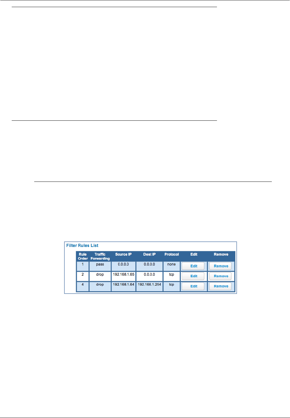
Filter Rules List
Your entries are displayed as a table.
Administrator’s Handbook
52
☛ NOTE:
Default Forwarding Filter
If you create one or more filters that have a matching action of forward, then action on a packet
matching none of the filters is to block any traffic.
Therefore, if the behavior you want is to force the routing of a certain type of packet and pass all oth-
ers through the normal routing mechanism, you must configure one filter to match the first type of
packet and apply Force Routing. A subsequent filter is required to match and forward all other pack-
ets.
Management IP traffic
If the Force Routing filter is applied to source IP addresses, it may inadvertently block communica-
tion with the router itself. You can avoid this by preceding the Force Routing filter with a filter that
matches the destination IP address of the Gateway itself.
Example:
To create a Packet Filter that will block telnet from one LAN client, block access to the Gateway’s web interface
from one LAN client and then allow all other traffic to pass from the LAN to the Gateway, you enable LAN Packet
Filter and create filters and then apply them as an inbound filter.
Input Rules:
Pass Source IP Address Destination IP Address Protocol
No 192.168.1.65 0.0.0.0 TCP
No 192.168.1.64 192.168.1.254 TCP
Yes 0.0.0.0 0.0.0.0 Any
53
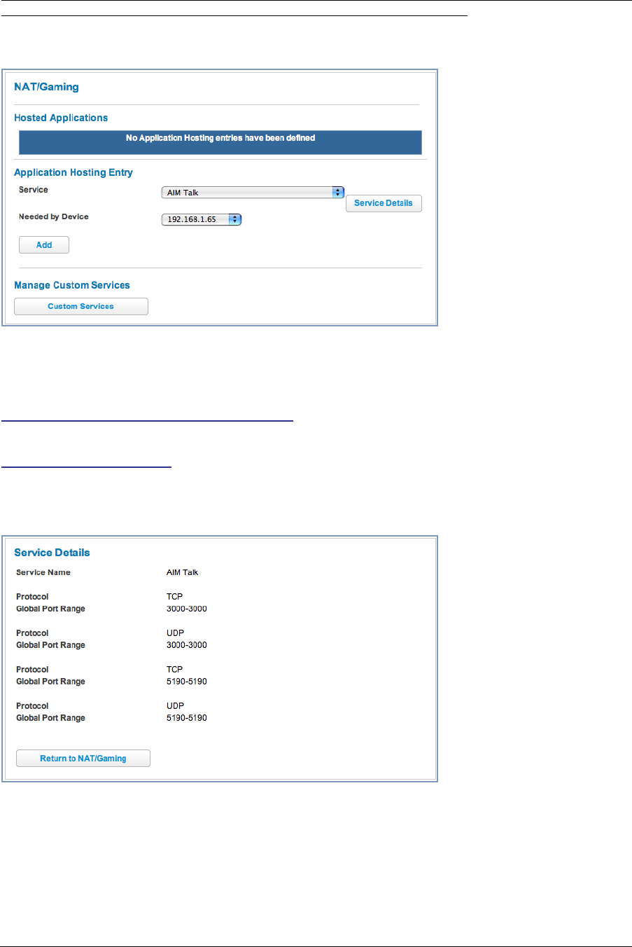
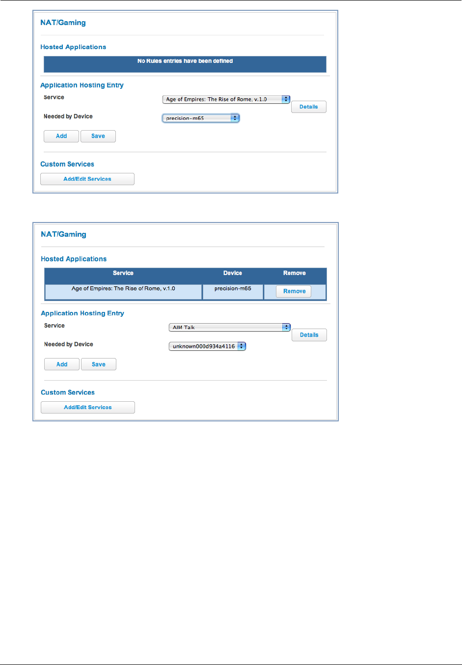
Link: NAT/Gaming
When you click the NAT/Gaming button, the NAT/Gaming page appears.
NAT/Gaming allows you to host internet applications when NAT is enabled. You can host different games and
software on different PCs.
From the Service pull-down menu, you can select any of a large number of predefined games and software. (See
“List of Supported Games and Software” on page 56.)
In addition to choosing from these predefined services you can also select a user defined custom service. (See
“Custom Services” on page 55.)
For each supported game or service, you can view the protocols and port ranges used by the game or service by
clicking the Service Details button. For example:
Select a hosting device from the Needed by Device pull-down menu.
1. Once you choose a software service or game, click Add.
2. Select a PC to host the software from the Select Host Device pull-down menu and
click Save.
Administrator’s Handbook
54
Each time you enable a software service or game your entry will be added to the list of Service names dis-
played on the NAT Configuration page.
To remove a game or software from the hosted list, choose the game or software you want to remove and click the
Remove button.
55
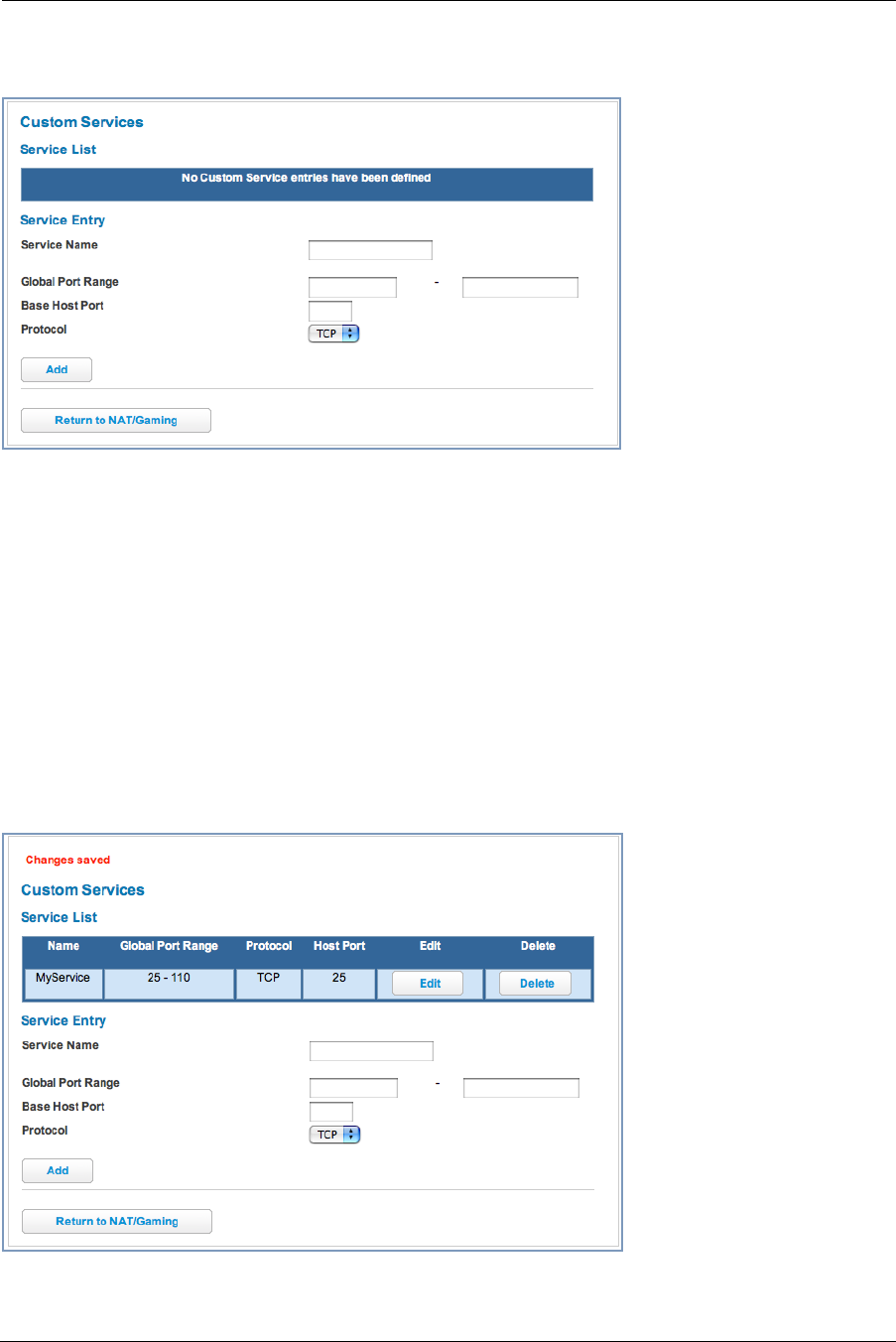
Custom Services
To configure a Custom Service, click the Add/Edit Services button. The Custom Services page appears.
Enter the following information:
◆Service Name: A unique identifier for the Custom Service.
◆Global Port Range: Range of ports on which incoming traffic will be received.
◆Base Host Port: The port number at the start of the port range your Gateway should use when forwarding traf-
fic of the specified type(s) to the internal IP address.
◆Protocol: Protocol type of Internet traffic, TCP or UDP.
Once you define a Custom Service it becomes available in the Application Hosting Entry Service menu as one
of the services to select.
Click the Add button.
Each time you enable a custom service your entry will be added to the list of Service names displayed on the
Custom Services page.
Changes are saved immediately.

Administrator’s Handbook
56
List of Supported Games and Software
AIM Talk Act of War - Direct Action Age of Empires II
Age of Empires, v.1.0 Age of Empires: The Rise of
Rome, v.1.0
Age of Mythology
Age of Wonders America's Army Apache
Asheron's Call Azureus Baldur's Gate I and II
Battlefield 1942 Battlefield Communicator Battlefield Vietnam
BitTornado BitTorrent Black and White
Blazing Angels Online Brothers in Arms - Earned in
Blood
Brothers in Arms Online
Buddy Phone CART Precision Racing, v 1.0 Calista IP Phone
Call of Duty Citrix Metaframe/ICA Client Close Combat III: The Russian
Front, v 1.0
Close Combat for Windows 1.0 Close Combat: A Bridge Too Far, v
2.0
Combat Flight Sim 2: WWII Pacific
Thr, v 1.0
Combat Flight Sim: WWII Europe
Series, v 1.0
Counter Strike DNS Server
Dark Reign Delta Force (Client and Server) Delta Force 2
Delta Force Black Hawk Down Diablo II Server Dialpad
DirecTV STB 1 DirecTV STB 2 DirecTV STB 3
Doom 3 Dues Ex Dune 2000
Empire Earth Empire Earth 2 F-16, Mig 29
F-22, Lightning 3 FTP Far Cry
Fighter Ace II GNUtella Grand Theft Auto 2 Multiplayer
H.323 compliant (Netmeeting,
CUSeeME)
HTTP HTTPS
Half Life Half Life 2 Steam Half Life 2 Steam Server
Half Life Steam Half Life Steam Server Halo
Hellbender for Windows, v 1.0 Heretic II Hexen II
Hotline Server ICQ 2001b ICQ Old
IMAP Client IMAP Client v.3 IPSec IKE
Internet Phone Jedi Knight II: Jedi Outcast Kali
KazaA Lime Wire Links LS 2000
Lord of the Rings Online MSN Game Zone MSN Game Zone DX
MSN Messenger Mech Warrior 3 MechWarrior 4: Vengeance
Medal of Honor Allied Assault Microsoft Flight Simulator 2000 Microsoft Flight Simulator 98

57
Microsoft Golf 1998 Edition, v
1.0
Microsoft Golf 1999 Edition Microsoft Golf 2001 Edition
Midtown Madness, v 1.0 Monster Truck Madness 2, v 2.0 Monster Truck Madness, v 1.0
Motocross Madness 2, v 2.0 Motocross Madness, v 1.0 NNTP
Need for Speed 3, Hot Pursuit Need for Speed, Porsche Net2Phone
Operation FlashPoint Outlaws POP-3
PPTP PlayStation Network Quake 2
Quake 3 Quake 4 Rainbow Six
RealAudio Return to Castle Wolfenstein Roger Wilco
Rogue Spear SMTP SNMP
SSH server ShoutCast Server SlingBox
Soldier of Fortune StarCraft StarLancer, v 1.0
Starfleet Command TFTP TeamSpeak
Telnet Tiberian Sun: Command and Con-
quer
Timbuktu
Total Annihilation Ultima Online Unreal Tournament Server
Urban Assault, v 1.0 VNC, Virtual Network Computing Warlords Battlecry
Warrock Westwood Online, Command and
Conquer
Win2000 Terminal Server
Wolfenstein Enemy Territory World of Warcraft X-Lite
XBox 360 Media Center XBox Live 360 Yahoo Messenger Chat
Yahoo Messenger Phone ZNES eDonkey
eMule eMule Plus iTunes
mIRC Auth-IdentD mIRC Chat mIRC DCC - IRC DCC
pcAnywhere (incoming)
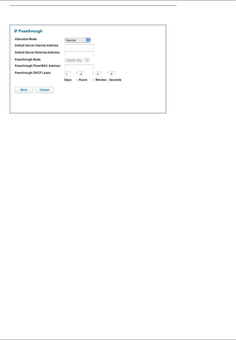
Administrator’s Handbook
58
Link: IP Passthrough
When you click the IP Passthrough button, the IP Passthrough page appears.
IP Passthrough
The IP Passthrough feature allows a single PC on the LAN to have the Router’s public address assigned to it. It
also provides PAT (NAPT) via the same public IP address for all other hosts on the private LAN subnet. Using IP
Passthrough:
◆The public WAN IP is used to provide IP address translation for private LAN computers.
◆The public WAN IP is assigned and reused on a LAN computer.
◆DHCP address serving can automatically serve the WAN IP address to a LAN computer.
When DHCP is used for addressing the designated passthrough PC, the acquired or configured WAN address
is passed to DHCP, which will dynamically configure a single-servable-address subnet, and reserve the
address for the configured PC’s MAC address. This dynamic subnet configuration is based on the local and
remote WAN address and subnet mask. If the WAN interface does not have a suitable subnet mask that is
usable, for example when using PPP or PPPoE, the DHCP subnet configuration will default to a class C sub-
net mask.
◆The Passthrough DHCP Lease – By default, the passthrough host's DHCP leases will be shortened to two
minutes. This allows for timely updates of the host's IP address, which will be a private IP address before the
WAN connection is established. After the WAN connection is established and has an address, the passthrough
host can renew its DHCP address binding to acquire the WAN IP address. You may alter this setting.
◆Click Save. Changes take effect immediately.
A restriction
Since both the Router and the passthrough host will use the same IP address, new sessions that conflict with
existing sessions will be rejected by the Router. For example, suppose you are a teleworker using an IPSec tunnel
from the Router and from the passthrough host. Both tunnels go to the same remote endpoint, such as the VPN
access concentrator at your employer’s office. In this case, the first one to start the IPSec traffic will be allowed;
the second one – since, from the WAN, it's indistinguishable – will fail.

59
NAT Default Server
This feature allows you to:
◆Direct your Gateway to forward all externally initiated IP traffic (TCP and UDP protocols only) to a default host
on the LAN, specified by your entry in the Internal Address field.
◆ Enable it for certain situations:
– Where you cannot anticipate what port number or packet protocol an in-bound application might use. For
example, some network games select arbitrary port numbers when a connection is opened.
– When you want all unsolicited traffic to go to a specific LAN host.
This feature allows you to direct unsolicited or non-specific traffic to a designated LAN station. With NAT “On” in
the Gateway, these packets normally would be discarded.
For instance, this could be application traffic where you don’t know (in advance) the port or protocol that will be
used. Some game applications fit this profile.
◆Click Save. Changes take effect immediately.
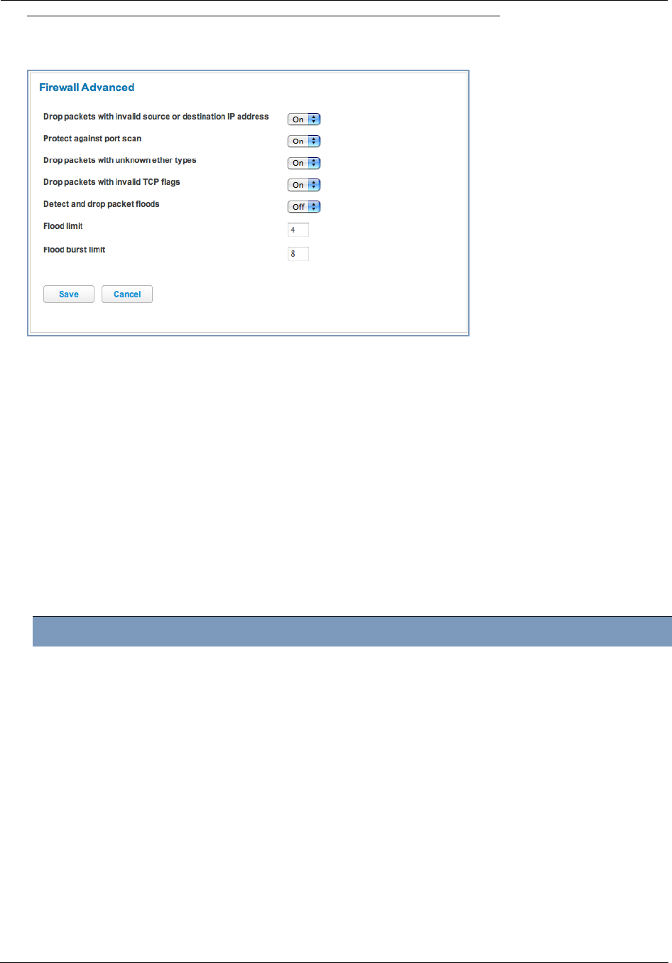
Administrator’s Handbook
60
Link: Firewall Advanced
When you click the Firewall Advanced button the Firewall Advanced screen appears.
All computer operating systems are vulnerable to attack from outside sources, typically at the operating system or
Internet Protocol (IP) layers. Stateful Inspection firewalls intercept and analyze incoming data packets to deter-
mine whether they should be admitted to your private LAN, based on multiple criteria, or blocked. Stateful inspec-
tion improves security by tracking data packets over a period of time, examining incoming and outgoing packets.
Outgoing packets that request specific types of incoming packets are tracked; only those incoming packets consti-
tuting a proper response are allowed through the firewall.
Stateful inspection is a security feature that prevents unsolicited inbound access when NAT is disabled. You can
configure UDP and TCP “no-activity” periods that will also apply to NAT time-outs if stateful inspection is enabled
on the interface. Stateful Inspection parameters are active on a WAN interface only if enabled on your Gateway.
Stateful inspection can be enabled on a WAN interface whether NAT is enabled or not.
DoS Protection – Denial-0f-Service attacks are common on the Internet, and can render an individual PC or a
whole network practically unusable by consuming all its resources. Your Gateway includes default settings to
block the most common types of DoS attacks. For special requirements or circumstances, a variety of additional
blocking characteristics is offered. See the following table.
If you make any changes here, click the Save button.
Menu item Function
Drop packets with invalid source or
destination IP address
Whether packets with invalid source or destination IP address(es)
are to be dropped
Protect against port scan Whether to detect and drop port scans.
Drop packets with unknown ether
types
Whether packets with unknown ether types are to be dropped
Drop packets with invalid TCP flags Whether packets with invalid TCP flag settings (NULL, FIN, Xmas,
etc.) should be dropped
Detect and drop packet floods Whether packet flooding should be detected and offending packets
be dropped
Flood limit (packets per second) Specifies the number limit of packets per second before dropping the
remainder.
Flood burst limit (maximum num-
ber of packets in a burst)
Specifies the number limit of packets in a single burst before dropping
the remainder.
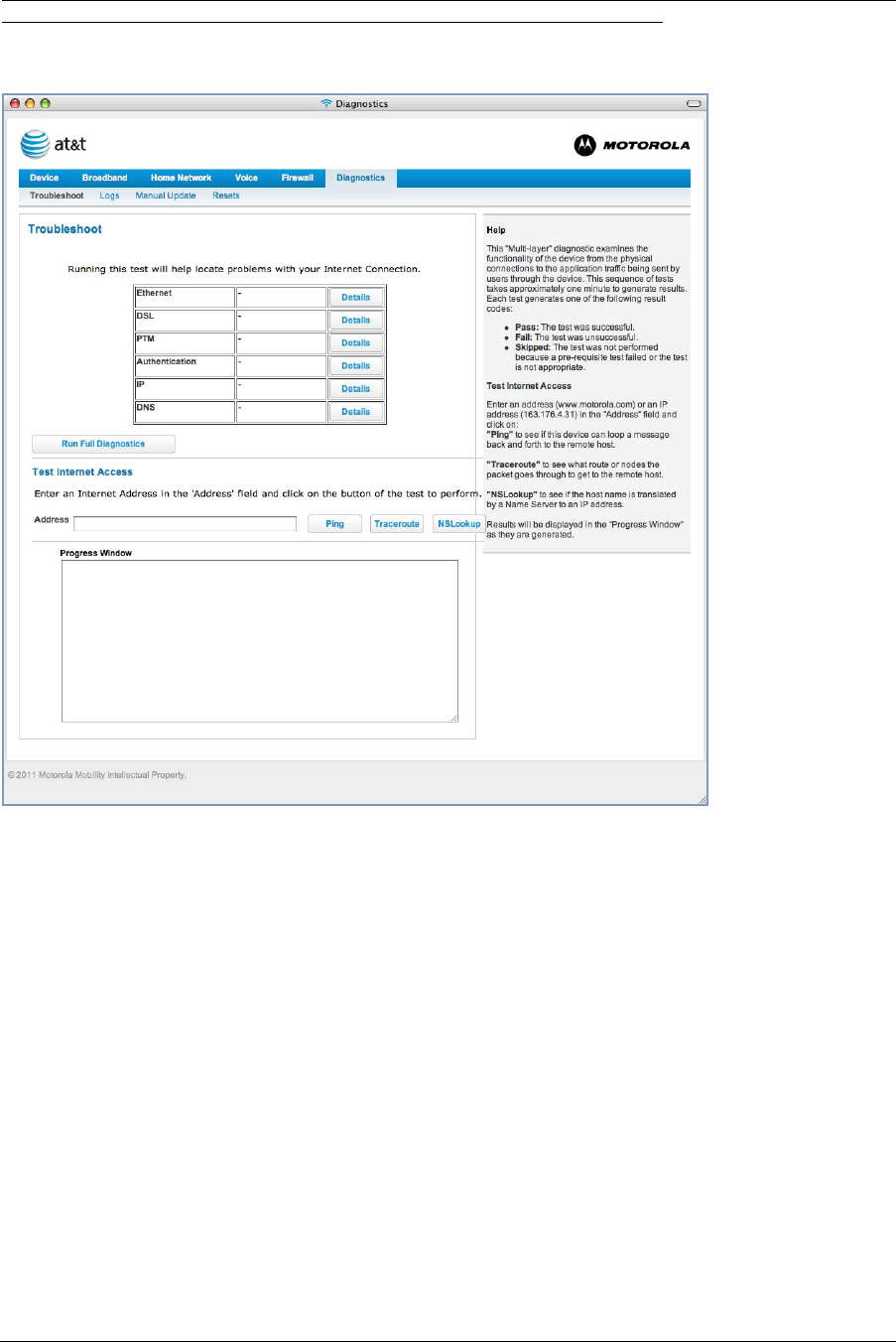
61
Diagnostics
When you click the Diagnostics tab, the Troubleshoot page appears.
This automated multi-layer test examines the functionality of the Router from the physical connections to the data
traffic being sent by users through the Router.
You can run all the tests in order by clicking the Run Full Diagnostics button.
The modem will automatically test a number of components to determine any problems. You can see detailed
results of the tests by clicking the Details buttons for each item.

Administrator’s Handbook
62
Here is an example of the Ethernet Details screen.
Test Internet Access
These tests send a PING from the modem to either the LAN or WAN to verify connectivity. A PING could be either
an IP address (163.176.4.32) or Domain Name (www.motorola.com). You enter a web address URL or an IP
address in the respective field and Select your Preferred protocol radio button, IPv4 or IPv6.
Click the Ping, Trace, or Lookup button.
Results will be displayed in the Progress Window as they are generated.
◆Ping - tests the “reachability” of a particular network destination by sending an ICMP echo request and waiting
for a reply.
◆Traceroute - displays the path to a destination by showing the number of hops and the router addresses of
these hops.
◆NSLookup - converts a domain name to its IP address and vice versa.
To use the Ping capability, type a destination address (domain name or IP address) in the text box and click the
Ping, Trace, or Lookup button. The results are displayed in the Progress Window.
This sequence of tests takes approximately one minute to generate results. Please wait for the test to run to com-
pletion.
Each test generates one of the following result codes:
Result Meaning
* PASS: The test was successful.
* FAIL: The test was unsuccessful.
* SKIPPED: The test was skipped because a test on which it depended failed.
* PENDING: The test timed out without producing a result. Try running the test again.
* WARNING: The test was unsuccessful. The Service Provider equipment your Modem connects to
may not support this test.

63
Below are some specific tests:
Action If PING fails, possible causes are:
From the Check Connection page:
Ping the internet default gateway IP address DSL is down, DSL or ATM settings are incorrect;
Gateway’s IP address or subnet mask are wrong;
gateway router is down.
Ping an internet site by IP address Site is down.
Ping an internet site by name Servers are down; site is down.
From a LAN PC:
Ping the Modem’s LAN IP address IP address and subnet mask of PC are not on the
same scheme as the Modem; cabling or other con-
nectivity issue.
Ping an internet site by IP address PC's subnet mask may be incorrect, site is down.
Ping an internet site by name DNS is not properly configured on the PC, site is
down.
Administrator’s Handbook
64
Link: Logs
When you click Logs, the Logs page appears.
The current status of the Router is displayed for all logs.
◆You can clear all log entries by clicking the Clear Log button.
◆You can save logs to a text (.TXT) file by clicking the Save to File button. This will download the file to your
browser’s default download location on your hard drive. The file can be opened with your favorite text editor.
☛ Note:
Some browsers, such as Internet Explorer for Windows XP, require that you specify the Motorola®
Gateway’s URL as a “Trusted site” in “Internet Options: Security”. This is necessary to allow the
“download” of the log text file to the PC.

65
The following is an example log portion saved as a .TXT file:
P0000-00-00T00:00:08 L6 sdb[306]: log buffer size set to 8192
P0000-00-00T00:00:08 L7 sdb[306]: libmotopia: Closing /dev/motopia
P0000-00-00T00:00:08 L7 sdb[306]: Loading platform module bcm_enet
P0000-00-00T00:00:08 L6 sdb[306]: SSL CA-root-cert directory is ready.
P0000-00-00T00:00:08 L6 sdb[306]: Hardware is 'NVG510'
P0000-00-00T00:00:09 L6 sdb[306]: S/N 157978490448, SKU 64
P0000-00-00T00:00:12 L5 sdb[306]: Wireless subsystem found
P0000-00-00T00:00:15 L5 sdb[306]: VOIP subsystem found
P0000-00-00T00:00:15 L7 sdb[306]: nm_add_supp1x entrypoint
P0000-00-00T00:00:15 L7 sdb[306]: netfilter: redirect object not found. skip prerouting rules
P0000-00-00T00:00:17 L3 sdb[306]: scheduler: no ntp object
P0000-00-00T00:00:17 L6 sdb[306]: ip6.route[1]: Setting state from 'unset' to 'down'
P0000-00-00T00:00:18 L5 sdb[306]: skip authorization-delay timer. not defaulted
P0000-00-00T00:00:18 L3 sdb[306]: ELAN: Error creating 'enet' 'power-save' object: Item not
found
P0000-00-00T00:00:18 L7 sdb[306]: Wi-Fi: Taking down phy.wl80211 interface wl0
P0000-00-00T00:00:18 L6 sdb[306]: Wi-Fi: Adding wireless port ssid-1 (wl0)
P0000-00-00T00:00:18 L6 sdb[306]: Wi-Fi: Adding wireless port ssid-2 (wl0.1)
P0000-00-00T00:00:18 L6 sdb[306]: Wi-Fi: Adding wireless port ssid-3 (wl0.2)
P0000-00-00T00:00:18 L6 sdb[306]: Wi-Fi: Adding wireless port ssid-4 (wl0.3)
P0000-00-00T00:00:18 L5 sdb[306]: DSL: EOC version 157978490448:NVG510:905012
P0000-00-00T00:00:18 L7 sdb[306]: enabling vc[1]
P0000-00-00T00:00:19 L5 sdb[306]: voipexe start returned ret=0
P0000-00-00T00:00:19 L5 sdb[306]: skip authorization-delay timer. not defaulted
P0000-00-00T00:00:19 L4 sdb[306]: Configured for IPDSLAM mode
P0000-00-00T00:00:19 L3 sdb[306]: start[8024] end[8036]
P0000-00-00T00:00:19 L6 sdb[306]: validate <basic> queue(1)
P0000-00-00T00:00:19 L6 sdb[306]: validate <basic> queue(2)
P0000-00-00T00:00:19 L6 sdb[306]: validate <basic> queue(3)
P0000-00-00T00:00:19 L6 sdb[306]: validate <basic> queue(4)
P0000-00-00T00:00:19 L6 sdb[306]: validate <basic> queue(5)
P0000-00-00T00:00:19 L6 sdb[306]: validate <basic> queue(6)
P0000-00-00T00:00:19 L6 sdb[306]: validate <priority> queue(7)
P0000-00-00T00:00:19 L6 sdb[306]: ip6_set_proc: setting </proc/sys/net/ipv6/conf/all/
disable_ipv6> to '1'
P0000-00-00T00:00:19 L6 sdb[306]: ip6_set_proc: setting </proc/sys/net/ipv6/conf/default/
disable_ipv6> to '1'
P0000-00-00T00:00:19 L6 sdb[306]: ip6_set_proc: setting </proc/sys/net/ipv6/conf/all/
forwarding> to '0'
P0000-00-00T00:00:23 L7 sdb[306]: Wi-Fi: First apply - apply everything
P0000-00-00T00:00:23 L7 sdb[306]: Wi-Fi: NAS daemon not found, not killing
P0000-00-00T00:00:23 L7 sdb[306]: Wi-Fi: Taking down phy.wl80211 interface wl0
P0000-00-00T00:00:23 L7 sdb[306]: Wi-Fi: Bringing up phy.wl80211 interface wl0
P0000-00-00T00:00:23 L6 sdb[306]: Wi-Fi: Starting autochannel scan...
P0000-00-00T00:00:24 L7 sdb[306]: Wi-Fi: SIOCDEVPRIVATE ioctl cmd=215 failed: Bad Argument
P0000-00-00T00:00:26 L6 sdb[306]: Wi-Fi: Autochannel found channel 11019
P0000-00-00T00:00:26 L7 sdb[306]: Wi-Fi: Taking down phy.wl80211 interface wl0
P0000-00-00T00:00:26 L7 sdb[306]: Wi-Fi: Bringing up phy.wl80211 interface wl0
P0000-00-00T00:00:26 L7 sdb[306]: Wi-Fi: Setting kernel ip link wl0 to up
P0000-00-00T00:00:26 L7 sdb[306]: Wi-Fi: Setting kernel ip link wl0.1 to down
P0000-00-00T00:00:26 L7 sdb[306]: Wi-Fi: Setting kernel ip link wl0.2 to down
P0000-00-00T00:00:26 L7 sdb[306]: Wi-Fi: Setting kernel ip link wl0.3 to down
P0000-00-00T00:00:26 L6 sdb[306]: Wi-Fi: EAPD daemon started (pid: 1030)
P0000-00-00T00:00:26 L6 sdb[306]: Wi-Fi: NAS daemon started, bringing up phy.wl80211.ssid[1]
P0000-00-00T00:00:26 L7 sdb[306]: Port ssid-1 sending UP event
P0000-00-00T00:00:26 L6 sdb[306]: DSL: Vectoring function is not supported.
P0000-00-00T00:00:26 L6 sdb[306]: DSL: Warning: PTM only.
P0000-00-00T00:00:27 L6 sdb[306]: DSL: set the NLNM Threshold value
...
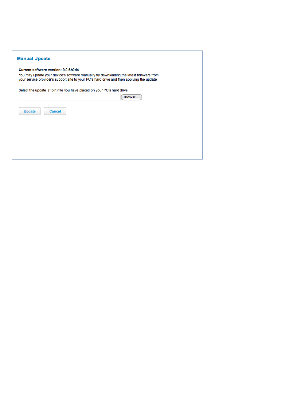
Administrator’s Handbook
66
Link: Manual Update
When you click Manual Update, the Manual Update page appears.
Operating System Software is what makes your Gateway run and occasionally it needs to be updated. Your Cur-
rent version is displayed at the top of the page.
To update your software from a file on your PC, you must first download the software from your Service Provider's
Support Site to your PC's hard drive.
◆Browse your computer for the operating system file you downloaded.
◆Click the Update button.
◆The installation may take a few minutes; wait for it to complete. You will be prompted to restart the Gateway.
◆Restart your Gateway. A counter will countdown 3 times before returning you to home. Your new operating
system will then be running.
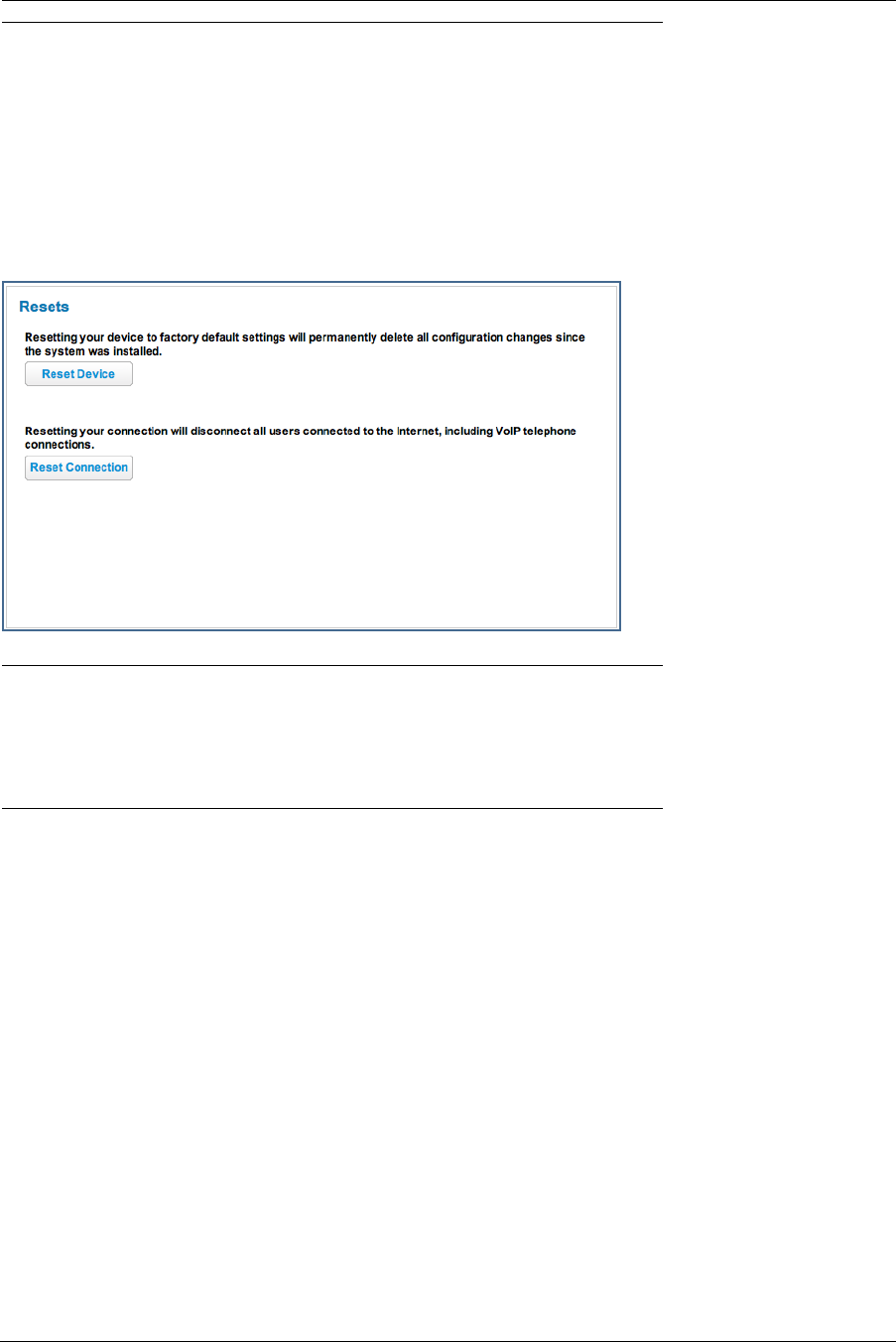
67
Link: Resets
In some cases, you may need to clear all the configuration settings and start over again to program the Motorola®
Gateway. You can perform a factory reset to do this.
It might also be useful to reset your connection to the Internet without deleting all of your configuration settings.
◆Click the Reset Device button to reset the Gateway back to its original factory default settings. You will be
prompted to make sure you want to do this.
◆Click the Reset Connection button to disconnect and reconnect all of your connections, including your VoIP
phones.
☛ NOTE:
Exercise caution before performing a Factory Reset. This will erase any configuration changes that
you may have made and allow you to reprogram your Gateway.

Administrator’s Handbook
68

69
CHAPTER 3 Basic Troubleshooting
This section gives some simple suggestions for troubleshooting problems with your Gateway’s initial configura-
tion.
Before troubleshooting, make sure you have
◆read the User Manual;
◆plugged in all the necessary cables; and
◆set your PC’s TCP/IP controls to obtain an IP address automatically.

Administrator’s Handbook
70
Status Indicator Lights
The first step in troubleshooting is to check the status indicator lights (LEDs) in the order outlined below.
Motorola® Gateway NVG510 status indicator lights
LED Action
Power
Solid Green = The device is powered.
Flashing Green = A Power-On Self-Test (POST) is in progress
Flashing Red = A POST failure (not bootable) or device malfunction occurred.
* When the device encounters a POST failure, all indicator lights on the front of the device
continuously flash.
Off = The unit has no AC power.
Ethernet
Solid Green = Powered device connected to the associated port (includes devices with
wake-on-LAN capability where a slight voltage is supplied to the Ethernet connection).
Flickering Green = Activity seen from devices associated with the port. The flickering of the
light is synchronized to actual data traffic.
Off = The device is not powered, no cable or no powered devices connected to the associ-
ated ports.
Wireless
Solid Green = WIFI is powered.
Flickering Green = Activity seen from devices connected via WIFI. The flickering of the light
is synchronized to actual data traffic.
Off = The device is not powered or no powered devices connected to the associated ports.
Wi-Fi
Setup
Flickering Green = Indicates when WPS is broadcasting.
Off = not in use, not broadcasting.
Broadband
Solid Green = Good broadband connection (i.e., good DSL Sync).
Flashing Green = Attempting broadband connection (i.e., DSL attempting sync).
Flashing Green & Red = If the broadband connection fails to be established for more than
three consecutive minutes the LED switches to Flashing Green when attempting or waiting
to establish a broadband connection alternating with a five second steady Red. This pattern
continues until the broadband connection is successfully established.
Flashing Red = No DSL signal on the line. This is only used when there is no signal, not dur-
ing times of temporary ‘no tone’ during the training sequence.
Off = The device is not powered.
Power
Ethernet
Side View
Wireless
Broadband
Service
Phone 1
Phone 2
Wi-Fi Setup

71
Motorola® Gateway NVG510 Rear View
Service
Solid Green = IP connected (The device has a WAN IP address from DHCP or 802.1x
authentication and the broadband connection is
up).
Flashing Green = Attempting PPP connection. Attempting IEEE 802.1X authentication or
attempting to obtain DHCP information.
Red = Device attempted to become IP connected and failed (no DHCP response, no PPPoE
response, 802.1x authentication failed, no IP address from IPCP, etc.). The Red state times
out after two minutes and the Service indicator light returns to the Off state.
Off = The device is not powered or the broadband connection is not present.
Phone 1, 2
Solid Green = The associated VoIP line has been registered with a SIP proxy server.
Flashing Green = Indicates a telephone is off-hook on the associated VoIP line.
Off = VoIP not in use, line not registered or Gateway power off.
LED Action
Factory Reset Switch
DC Power PortWPS PushbuttonEthernet Ports
Phone Port
(use splitter for
2 phones)
DSL Port

Administrator’s Handbook
72
LED Function Summary Matrix
Power
Solid Green =
The device is
powered.
Flashing
Green = A
Power-On Self-
Test (POST) is
in progress
Flashing Red
= A POST fail-
ure (not boota-
ble) or device
malfunction
occurred.
* When the
device encoun-
ters a POST
failure, all indi-
cator lights on
the front of the
device continu-
ously flash.
Off = The unit
has no AC
power.
Ethernet
Solid Green =
Powered
device con-
nected to the
associated port
(includes
devices with
wake-on-LAN
capability
where a slight
voltage is sup-
plied to the
Ethernet con-
nection).
Flashing
Green = Activ-
ity seen from
devices associ-
ated with the
port. The flick-
ering of the light
is synchro-
nized to actual
data traffic.
Off = The
device is not
powered, no
cable or no
powered
devices con-
nected to the
associated
ports.
Wireless
Solid Green =
WIFI is pow-
ered.
Flashing
Green = Activ-
ity seen from
devices con-
nected via
WIFI. The flick-
ering of the light
is synchro-
nized to actual
data traffic.
Off = The
device is not
powered or no
powered
devices con-
nected to the
associated
ports.
Phone 1, 2
Solid Green =
The associated
VoIP line has
been regis-
tered with a SIP
proxy server.
Flashing
Green = Indi-
cates a tele-
phone is off-
hook on the
associated
VoIP line.
Off = VoIP not
in use, line not
registered or
Gateway power
off.
WPS
Flashing
Green = Indi-
cates when
WPS is broad-
casting.
Off = not in
use, not broad-
casting.

73
Broadband
Solid Green =
Good broad-
band connec-
tion (i.e., good
DSL Sync).
Flashing
Green =
Attempting
broadband con-
nection (i.e.,
DSL attempt-
ing sync).
Flashing
Green & Red =
If the broad-
band connec-
tion fails to be
established for
more than three
consecutive
minutes the
LED switches
to Flashing
Green when
attempting or
waiting to
establish a
broadband con-
nection alter-
nating with a
five second
steady Red.
This pattern
continues until
the broadband
connection is
successfully
established.
Flashing Red
= No DSL sig-
nal on the line.
This is only
used when
there is no sig-
nal, not during
times of tempo-
rary ‘no tone’
during the train-
ing sequence.
Off = The
device is not
powered.
Service
Solid Green =
IP connected
(The device has
a WAN IP
address from
DHCP or
802.1x authen-
tication and the
broadband con-
nection is up).
Flashing
Green =
Attempting PPP
connection.
Attempting
IEEE 802.1X
authentication
or attempting to
obtain DHCP
information.
Red = Device
attempted to
become IP con-
nected and
failed (no
DHCP
response, no
PPPoE
response,
802.1x authen-
tication failed,
no IP address
from IPCP,
etc.). The Red
state times out
after two min-
utes and the
Service indica-
tor light returns
to the Off state.
Off = The
device is not
powered or the
broadband con-
nection is not
present.

Administrator’s Handbook
74
If a status indicator light does not look correct, look for these possible problems:
If LED is
not Lit Possible problems
Power
◆Make sure the power adapter is plugged into the DSL Modem properly.
◆Try a known good wall outlet.
◆If a power strip is used, make sure it is switched on.
Broadband
◆Make sure that any telephone has a microfilter installed.
◆Make sure that you are using the correct cable. The DSL cable is the thinner stan-
dard telephone cable and labeled “Data Cable.”
◆Make sure the DSL cable is plugged into the correct wall jack.
◆Make sure the DSL cable is plugged into the DSL port on the DSL Modem.
◆Make sure the DSL line has been activated at the central office DSLAM.
◆Make sure the DSL Modem is not plugged into a micro filter.
Ethernet
◆Make sure the you are using the yellow Ethernet cable, not the DSL cable. The
Ethernet cable is thicker than the standard telephone cable.
◆Make sure the Ethernet cable is securely plugged into the Ethernet jack on the PC.
◆Make sure the Ethernet cable is securely plugged into the Ethernet port on the DSL
Modem.
◆Make sure you have Ethernet drivers installed on the PC.
◆Make sure the PC’s TCP/IP Properties for the Ethernet Network Control Panel is set
to obtain an IP address via DHCP.
◆Make sure the PC has obtained an address in the 192.168.1.x range. (You may have
changed the subnet addressing.)
◆Make sure the PC is configured to access the Internet over a LAN.
◆Disable any installed network devices (Ethernet, HomePNA, wireless) that are not
being used to connect to the DSL Modem.

75
Factory Reset Switch
Lose your Access Code? This section shows how to reset the Motorola® Gateway so that you can access the
configuration screens once again.
☛ NOTE: Keep in mind that all of your settings will need to be reconfigured.
If you don't have an Access Code, the only way to access the Motorola® Gateway is the following:
1. Referring to the diagram below, find the round Reset Switch opening.
2. Carefully insert the point of a pen or an unwound paperclip into the opening.
◆If you press the factory reset button for less than ten (10) seconds, the device will be rebooted.
The indicator lights on the device will respond immediately and start blinking red within one (1) second of the
reset button being pressed.
This will occur independent of the fact that the button is still being pressed or has been released. The indicator
lights will flash for a minimum of five seconds, even if the reset button is released prior to five seconds after it
has been depressed. If the reset button is held for more than 5 seconds, then it will continue to flash until
released or until 10 seconds (see below).
◆If you press the factory reset button for a longer period of time, the device will be reset to the factory default
shipped settings.
If the button is held for ten seconds, the Power indicator continues to flash, for an additional 5 seconds and
then the indicator lights will return to their normal operating mode, independent of whether or not the reset but-
ton is still depressed.
Factory Reset Switch: Push to clear all settings

Administrator’s Handbook
76

77
CHAPTER 4 Command Line Interface
The Motorola Gateway operating software includes a command line interface (CLI) that lets you access your
Motorola Gateway over a telnet connection. You can use the command line interface to enter and update the unit’s
configuration settings, monitor its performance, and restart it.
This chapter covers the following topics:
◆“Overview” on page 79
◆“Starting and Ending a CLI Session” on page 81
◆“Using the CLI Help Facility” on page 81
◆“About SHELL Commands” on page 82
◆“SHELL Commands” on page 83
◆“About CONFIG Commands” on page 92
◆“CONFIG Commands” on page 95
◆“Debug Commands” on page 132
CONFIG Commands
“Connection commands” on page 95
“Filterset commands” on page 96
“Queue commands” on page 100
“IP Gateway commands” on page 101
“IPv6 Commands” on page 101
“IP DNS commands” on page 106
“IP IGMP commands” on page 107
“NTP commands” on page 109
“Application Layer Gateway (ALG) commands” on page 110
“Dynamic DNS Commands” on page 110
“Link commands” on page 111
“Management commands” on page 113
“Remote access commands” on page 115
“Physical interfaces commands” on page 117
“PPPoE relay commands” on page 120
“NAT Pinhole commands” on page 121
“Security Stateful Packet Inspection (SPI) commands” on page 121


79
Overview
The CLI has two major command modes: SHELL and CONFIG. Summary tables that list the commands are pro-
vided below. Details of the entire command set follow in this section.
SHELL Commands
Command Status and/or Description
arp to send ARP request
atmping to send ATM OAM loopback
clear to erase all stored configuration information
clear_certificate to remove an SSL certificate that has been installed
clear_log to erase all stored log info in flash memory
configure to configure unit's options
diagnose to run self-test
download to download config file
exit to quit this shell
help to get more: “help all” or “help help”
install to download and program an image into flash
log to add a message to the diagnostic log
loglevel to report or change diagnostic log level
netstat to show IP information
nslookup to send DNS query for host
ping to send ICMP Echo request
quit to quit this shell
reset to reset subsystems
restart to restart unit
show to show system information
start to start subsystem
status to show basic status of unit
telnet to telnet to a remote host
traceroute to send traceroute probes
upload to upload config file
view to show configuration information
who to show who is using the shell

Administrator’s Handbook
80
CONFIG Commands
Command Verbs Status and/or Description
delete Delete configuration list data
help Help command option
save Save configuration data
script Print configuration data
set Set configuration data
validate Validate configuration settings
view View configuration data
Keywords
conn Connection options
ip TCP/IP protocol options
dns Domain Name System options
igmp IGMP configuration options
ntp Network Time Protocol options
gateway Gateway options
link WAN link options
mgmt System management options
phy Physical interface options
dsl DSL configuration options
enet Ethernet options
pinhole Pinhole options
system Gateway’s system options
log System activity logging options
Command Utilities
top Go to top level of configuration mode
quit Exit from configuration mode; return to shell mode
exit Exit from configuration mode; return to shell mode

81
Starting and Ending a CLI Session
Open a telnet connection from a workstation on your network.
You initiate a telnet connection by issuing the following command from an IP host that supports telnet, for exam-
ple, a personal computer running a telnet application such as NCSA Telnet.
telnet <
ip_address
>
You must know the IP address of the Motorola Gateway before you can make a telnet connection to it. By default,
your Motorola Gateway uses 192.168.1.254 as the IP address for its LAN interface. You can use a Web browser
to configure the Motorola Gateway IP address.
Logging In
The command line interface log-in process emulates the log-in process for a UNIX host. To logon, enter the user-
name and your password.
Entering the administrator password lets you display and update all Motorola Gateway settings.
When you have logged in successfully, the command line interface lists the username and the security level asso-
ciated with the password you entered in the diagnostic log.
Ending a CLI Session
You end a command line interface session by typing quit from the SHELL node of the command line interface
hierarchy.
Using the CLI Help Facility
The help command lets you display on-line help for SHELL and CONFIG commands. To display a list of the com-
mands available to you from your current location within the command line interface hierarchy, enter help or
type a question mark (?).
To obtain help for a specific CLI command, type help <command>. You can truncate the
help
command to
h
or a question mark when you request help for a CLI command.

Administrator’s Handbook
82
About SHELL Commands
You begin in SHELL mode when you start a CLI session. SHELL mode lets you perform the following tasks with
your Motorola Gateway:
◆Monitor its performance
◆Display and reset Gateway statistics
◆Issue administrative commands to restart Motorola Gateway functions
SHELL Prompt
When you are in SHELL mode, the CLI prompt is the name of the Motorola Gateway followed by a right angle
bracket (>). For example, if you open a CLI connection to the Motorola Gateway named “Motorola-3000/
9437188,” you would see
Motorola-3000/9437188>
as your CLI prompt.
SHELL Command Shortcuts
You can truncate most commands in the CLI to their shortest unique string. For example, you can use the trun-
cated command
q
in place of the full
quit
command to exit the CLI. However, you would need to enter
rese
for
the
reset
command, since the first characters of
reset
are common to the
restart
command.
The only commands you cannot truncate are
restart
and
clear
. To prevent accidental interruption of communi-
cations, you must enter the
restart
and
clear
commands in their entirety.
You can use the Up and Down arrow keys to scroll backward and forward through recent commands you have
entered. Alternatively, you can use the
!!
command to repeat the last command you entered.

83
SHELL Commands
Common Commands
arp nnn.nnn.nnn.nnn
Sends an Address Resolution Protocol (ARP) request to match the
nnn.nnn.nnn.nnn
IP address to an
Ethernet hardware address.
clear [ yes ]
Clears the configuration settings in a Motorola Gateway. You are prompted to confirm the clear command by
entering yes.
clear_certificate
Removes an SSL certificate that has been installed.
configure
Puts the command line interface into Configure mode, which lets you configure your Motorola Gateway with Con-
fig commands. Config commands are described starting on page 95.
download [ server_address ] [ filename ] [ confirm ]
This command installs a file of configuration parameters into the Motorola Gateway from a TFTP (Trivial File
Transfer Protocol) server. The TFTP server must be accessible on your Ethernet network.
You can include one or more of the following arguments with the download command. If you omit arguments, the
console prompts you for this information.
◆The
server_address
argument identifies the IP address of the TFTP server from which you want to copy
the Motorola Gateway configuration file.
◆The
filename
argument identifies the path and name of the configuration file on the TFTP server.
◆If you include the optional confirm keyword, the download begins as soon as all information is entered.
You can also download an SSL certificate file from a trusted Certification Authority (CA), on platforms that support
SSL, as follows:
download [-cert] [server_address ] [filename] [confirm]
install [ server_address ] [ filename ] [ confirm ]
Downloads a new version of the Motorola Gateway operating software from a TFTP (Trivial File Transfer Protocol)
server, validates the software image, and programs the image into the Motorola Gateway memory. After you install
new operating software, you must restart the Motorola Gateway.
The
server_address
argument identifies the IP address of the TFTP server on which your Motorola Gateway
operating software is stored. The
filename
argument identifies the path and name of the operating software file
on the TFTP server.
If you include the optional keyword
confirm
, you will not be prompted to confirm whether or not you want to per-
form the operation.

Administrator’s Handbook
84
log message_string
Adds the message in the
message_string
argument to the Motorola Gateway diagnostic log.
loglevel [ level ]
Displays or modifies the types of log messages you want the Motorola Gateway to record. If you enter the
loglevel command without the optional
level
argument, the command line interface displays the current
log level setting.
You can enter the loglevel command with the
level
argument to specify the types of diagnostic messages
you want to record. All messages with a level number equal to or greater than the level you specify are recorded.
For example, if you specify loglevel 3, the diagnostic log will retain high-level informational messages (level 3),
warnings (level 4), and failure messages (level 5).
Use the following values for the
level
argument:
◆1 or low – Low-level informational messages or greater; includes trivial status messages.
◆2 or medium – Medium-level informational messages or greater; includes status messages that can help
monitor network traffic.
◆3 or high – High-level informational messages or greater; includes status messages that may be significant
but do not constitute errors.
◆4 or warning – Warnings or greater; includes recoverable error conditions and useful operator informa-
tion.
◆5 or failure – Failures; includes messages describing error conditions that may not be recoverable.
netstat -i
Displays the IP interfaces for your Motorola Gateway.
netstat -r
Displays the IP routes stored in your Motorola Gateway.
nslookup [ hostname | ip_address ]
Performs a domain name system lookup for a specified host.
◆The
hostname
argument is the name of the host for which you want DNS information; for example,
nslookup klaatu
.
◆The
ip_address
argument is the IP address, in dotted decimal notation, of the device for which you want
DNS information.
ping [-s size] [-c count ] [ hostname | ip_address ]
Causes the Motorola Gateway to issue a series of ICMP Echo requests for the device with the specified name or
IP address.
◆The
hostname
argument is the name of the device you want to ping; for example,
ping ftp.motorola.com
.
◆The
ip_address
argument is the IP address, in dotted decimal notation, of the device you want to locate. If
a host using the specified name or IP address is active, it returns one or more ICMP Echo replies, confirming
that it is accessible from your network.
◆The
-s
size
argument lets you specify the size of the ICMP packet.
◆The
-c
count
argument lets you specify the number of ICMP packets generated for the ping request. Values
greater than 250 are truncated to 250.

85
You can use the ping command to determine whether a hostname or IP address is already in use on your net-
work. You cannot use the ping command to ping the Motorola Gateway’s own IP address.
quit
Exits the Motorola Gateway command line interface.
reset arp
Clears the Address Resolution Protocol (ARP) cache on your unit.
reset crash
Clears crash-dump information, which identifies the contents of the Motorola Gateway registers at the point of sys-
tem malfunction.
reset dhcp server
Clears the DHCP lease table in the Motorola Gateway.
reset enet [ all ]
Resets Ethernet statistics to zero. Resets individual LAN switch port statistics as well as wireless and WAN Ether-
net statistics (where applicable).
reset firewall-log
Rewinds the firewall log to the first entry.
reset ipmap
Clears the IPMap table (NAT).
reset log
Rewinds the diagnostic log display to the top of the existing Motorola Gateway diagnostic log. The reset log
command does not clear the diagnostic log. The next show log command will display information from the
beginning of the log file.
reset wan
This function resets WAN interface statistics.
reset wepkeys
This function allows you to force your wireless WEP key settings back to the default values, if there are default val-
ues. For example, on some models, the WEP keys are based on the serial number. This allows you to get back
those default settings if you have changed them without the need to reset the entire configuration of the unit.
restart [ seconds ]
Restarts your Motorola Gateway. If you include the optional
seconds
argument, your Motorola Gateway will
restart when the specified number of seconds have elapsed. You must enter the complete restart command
to initiate a restart.

Administrator’s Handbook
86
show all-info
Displays all settings currently configured in the Motorola Gateway.
show bridge interfaces
Displays bridge interfaces maintained by the Motorola Gateway.
show bridge table
Displays the bridging table maintained by the Motorola Gateway.
show config
Dumps the Motorola Gateway’s configuration script just as the script command does in config mode.
show crash
Displays the most recent crash information, if any, for your Motorola Gateway.
show daylight-savings
Displays the auto-daylight savings time settings information.
show dhcp agent
Displays DHCP relay-agent leases.
show dhcp server leases
Displays the DHCP leases stored in RAM by your Motorola Gateway.
show diffserv
Displays the Differentiated Services and QoS values configured in the Motorola Gateway.
show dslf device-association
Displays LAN devices that conform with the TR111 Gateway requirement. It displays - IP Address, Manufacture
OUI and Serial number.
show enet [ all ]
Displays Ethernet interface statistics maintained by the Motorola Gateway. Supports display of individual LAN
switch port statistics as well as WAN Ethernet statistics (where applicable).
Example:
Ethernet driver full statistics - 10/100 Ethernet
Port Status: Link up
Type: 100BASET Duplex: Full
General:
Transmit OK : 434
Receive OK : 267

87
Tx Errors : 0
Rx Errors : 0
Receiver:
Incompl Packet Errors : 0
No RBD's For Packet : 0
Carrier Sense Lost : 0
Deferred Replen : 0
Transmitter:
TX Retries : 0
Single Collisions : 0
No Buf For Packet : 0
Upper Layers:
Rx No Handler : 0
Rx No Message : 0
Rx Octets : 30773
Rx Unicast Pkts : 267
Rx Multicast Pkts : 0
Tx Discards : 0
Tx Octets : 31692
10/100 Ethernet phy.enet.port
Port Status: Link up
Duplex: Full-duplex active
Speed: 100BASE-T
Transmit OK : 434
Transmit unicastpkts : NA
Receive OK : 267
Receive unicastpkts : 267
show group-mgmt
Displays the IGMP Snooping Table. See “IP IGMP commands” on page 107 for detailed explanation.
show ip arp
Displays the Ethernet address resolution table stored in your Motorola Gateway.
show ip igmp
Displays the contents of the IGMP Group Address table and the IGMP Report table maintained by your Motorola
Gateway.
show ip interfaces
Displays the IP interfaces for your Motorola Gateway.
show ip firewall
Displays firewall statistics.

Administrator’s Handbook
88
show ip lan-discovery
Displays the LAN Host Discovery Table of hosts on the wired or wireless LAN, and whether or not they are cur-
rently online.
show ip routes
Displays the IP routes stored in your Motorola Gateway.
show ipmap
Displays IPMap table (NAT).
6rd-check 6rd_ip_v6_conn_name
Sends out 6rd loopback packets to the 6rd BG. Verifies 6rd connectivity to the 6rd BG
show ipv6 interfaces
Display IPv6 interfaces.
show ipv6 routes
Display IPv6 route table.
show ipv6 neighbors
Display IPv6 neighbor table.
show ipv6 dhcp server leases
Display DHCPv6 server lease table.
show ipv6 statistics
Display IPv6 statistics information.
show log
Displays blocks of information from the Motorola Gateway diagnostic log. To see the entire log, you can repeat the
show log command or you can enter show log all.
show memory [ all ]
Displays memory usage information for your Motorola Gateway. If you include the optional
all
argument, your
Motorola Gateway will display a more detailed set of memory statistics.
show pppoe
Displays status information for each PPPoE socket, such as the socket state, service names, and host ID values.
show rootcert [ all | supplicant | openssl ]
Dumps the Subject line for the list of all the trusted root certificates for the supplicant, which is currently a superset
of the OpenSSL trusted root certificates.

89
This syntax is for the 802.1x-supplicant-supported builds only. The openssl trust list is used in all TLS/SSL situa-
tions except the 802.1X supplicant.
The default, if you don't append a qualifier, is all. all will show both 802.1x supplicant and openssl trust list root
certs; supplicant will show the supplicant trust list root certs; openssl will show openssl trust list root certs
show rtsp
Displays RTSP ALG session activity data.
show status
Displays the current status of a Motorola Gateway, the device's hardware and software revision levels, a summary
of errors encountered, and the length of time the Motorola Gateway has been running since it was last restarted.
Identical to the status command.
show summary
Displays a summary of WAN, LAN, and Gateway information.
show vlan
Displays detail of VLAN status and statistics.
show wireless [ all ]
Shows wireless status and statistics.
show wireless clients [ MAC_address ]
Displays details on connected clients, or more details on a particular client if the MAC address is added as an
argument.
telnet [ hostname | ip_address ] [ port ]
Lets you open a telnet connection to the specified host through your Motorola Gateway.
◆The
hostname
argument is the name of the device to which you want to connect; for example,
telnet
ftp.Motorola.com
.
◆The
ip_address
argument is the IP address, in dotted decimal notation, of the device to which you want to
connect.
◆The
port
argument is the number of t he port over which you want to open a telnet session.
traceroute ( ip_address | hostname )
Traces the routing path to an IP destination.
upload [ server_address ] [ filename ] [ confirm ]
Copies the current configuration settings of the Gateway to a TFTP (Trivial File Transfer Protocol) server. The
TFTP server must be accessible on your Ethernet network. The
server_address
argument identifies the IP
address of the TFTP server on which you want to store the Motorola Gateway settings. The
filename
argu-
ment identifies the path and name of the configuration file on the TFTP server. If you include the optional con-
firm keyword, you will not be prompted to confirm whether or not you want to perform the operation.

Administrator’s Handbook
90
view config
Dumps the Motorola Gateway’s configuration just as the view command does in config mode.
who
Displays the names of the current shell and PPP users.
WAN Commands
atmping vccn [ segment | end-to-end ]
Lets you check the ATM connection reachability and network connectivity. This command sends five Operations,
Administration, and Maintenance (OAM) loopback calls to the specified vpi/vci destination. There is a five second
total timeout interval.
Use the segment argument to ping a neighbor switch.
Use the end-to-end argument to ping a remote end node.
reset dhcp client release [ vcc-id ]
Releases the DHCP lease the Motorola Gateway is currently using to acquire the IP settings for the specified DSL
port. The
vcc-id
identifier is an “index” letter in the range B-I, and does not directly map to the VCC in use.
Enter the reset dhcp client release command without the variable to see the letter assigned to
each virtual circuit.
reset dhcp client renew [ vcc-id ]
Renews the DHCP lease the Motorola Gateway is currently using to acquire the IP settings for the specified DSL
port. The
vcc-id
identifier is an “index” letter in the range B-I, and does not directly map to the VCC in use.
Enter the reset dhcp client release without the variable to see the letter assigned to each virtual
circuit.
reset dsl
Resets any open DSL connection.
reset ppp vccn
Resets the point-to-point connection over the specified virtual circuit. This command only applies to virtual circuits
that use PPP framing.
show atm [all]
Displays ATM statistics for the Motorola Gateway. The optional all argument displays a more detailed set of ATM
statistics.
show dsl [ all ]
Displays DSL port statistics, such as upstream and downstream connection rates and noise levels.

91
show ppp [{ stats | lcp | ipcp }]
Displays information about open PPP links. You can display a subset of the PPP statistics by including an optional
stats, lcp, or ipcp argument for the show ppp command.
start ppp vccn
Opens a PPP link on the specified virtual circuit.

Administrator’s Handbook
92
About CONFIG Commands
You reach the configuration mode of the command line interface by typing
configure
(or any truncation of
con-
figure
, such as
con
or
config
) at the CLI SHELL prompt.
CONFIG Mode Prompt
When you are in CONFIG mode, the CLI prompt consists of the name of the Motorola Gateway followed by your
current node in the hierarchy and two right angle brackets (>>). For example, when you enter CONFIG mode (by
typing
config
at the SHELL prompt), the Motorola-3000/9437188 (top)>> prompt reminds you
that you are at the top of the CONFIG hierarchy. If you move to the ip node in the CONFIG hierarchy (by typing
ip at the CONFIG prompt), the prompt changes to Motorola-3000/9437188 (ip)>> to identify your
current location.
Some CLI commands are not available until certain conditions are met. For example, you must enable IP for an
interface before you can enter IP settings for that interface.
Navigating the CONFIG Hierarchy
◆Moving from CONFIG to SHELL — You can navigate from anywhere in the CONFIG hierarchy back to the
SHELL level by entering quit at the CONFIG prompt and pressing Return.
Motorola-3000/9437188 (top)>> quit
Motorola-3000/9437188 >
◆Moving from
top
to a subnode — You can navigate from the top node to a subnode by entering the node
name (or the significant letters of the node name) at the CONFIG prompt and pressing RETURN. For example,
you move to the IP subnode by entering ip and pressing RETURN.
Motorola-3000/9437188 (top)>> ip
Motorola-3000/9437188 (ip)>>
As a shortcut, you can enter the significant letters of the node name in place of the full node name at the CONFIG
prompt. The significant characters of a node name are the letters that uniquely identify the node. For example,
since no other CONFIG node starts with b, you could enter one letter (“b”) to move to the bridge node.
◆Jumping down several nodes at once — You can jump down several levels in the CONFIG hierarchy by
entering the complete path to a node.
◆Moving up one node — You can move up through the CONFIG hierarchy one node at a time by entering the
up command.
◆Jumping to the top node — You can jump to the top level from anywhere in the CONFIG hierarchy by enter-
ing the top command.
◆Moving from one subnode to another — You can move from one subnode to another by entering a partial
path that identifies how far back to climb.
◆Moving from any subnode to any other subnode — You can move from any subnode to any other subnode
by entering a partial path that starts with a top-level CONFIG command.
◆Scrolling backward and forward through recent commands — You can use the Up and Down arrow keys
to scroll backward and forward through recent commands you have entered. When the command you want
appears, press Enter to execute it.
Entering Commands in CONFIG Mode
CONFIG commands consist of keywords and arguments. Keywords in a CONFIG command specify the action
you want to take or the entity on which you want to act. Arguments in a CONFIG command specify the values
appropriate to your site. For example, the CONFIG command

93
set ip ethernet A ip_address
consists of two keywords (
ip
, and
ethernet
A
) and one argument (
ip_address
). When you use the com-
mand to configure your Gateway, you would replace the argument with a value appropriate to your site.
For example:
set ip ethernet A 192.31.222.57
Guidelines: CONFIG Commands
The following table provides guidelines for entering and formatting CONFIG commands.
If a command is ambiguous or miskeyed, the CLI prompts you to enter additional information. For example, you
must specify which virtual circuit you are configuring when you are setting up a Motorola Gateway.
Displaying Current Gateway Settings
You can use the
view
command to display the current CONFIG settings for your Motorola Gateway. If you enter
the
view
command at the top level of the CONFIG hierarchy, the CLI displays the settings for all enabled func-
tions. If you enter the
view
command at an intermediate node, you see settings for that node and its subnodes.
Step Mode: A CLI Configuration Technique
The Motorola Gateway command line interface includes a step mode to automate the process of entering configu-
ration settings. When you use the CONFIG step mode, the command line interface prompts you for all required
and optional information. You can then enter the configuration values appropriate for your site without having to
enter complete CLI commands.
When you are in step mode, the command line interface prompts you to enter required and optional settings. If a
setting has a default value or a current setting, the command line interface displays the default value for the com-
mand in parentheses. If a command has a limited number of acceptable values, those values are presented in
brackets, with each value separated by a vertical line. For example, the following CLI step command indicates that
the default value is off and that valid entries are limited to on and off.
Command
component Rules for entering CONFIG commands
Command verbs CONFIG commands must start with a command verb (set, view, delete).
You can truncate CONFIG verbs to three characters (set, vie, del).
CONFIG verbs are case-insensitive. You can enter “SET,” “Set,” or “set.”
Keywords Keywords are case-insensitive. You can enter “Ethernet,” “ETHERNET,” or “ethernet” as a
keyword without changing its meaning.
Keywords can be abbreviated to the length that they are differentiated from other key-
words.
Argument Text Text strings can be as many as 64 characters long, unless otherwise specified. In some
cases they may be as long as 255 bytes.
Special characters are represented using backslash notation.
Text strings may be enclosed in double (“) or single (‘) quote marks. If the text string
includes an embedded space, it must be enclosed in quotes.
Special characters are represented using backslash notation.
Numbers Enter numbers as integers, or in hexadecimal, where so noted.
IP addresses Enter IP addresses in dotted decimal notation (0 to 255).

Administrator’s Handbook
94
option (off) [on | off]: on
You can accept the default value for a field by pressing the Return key. To use a different value, enter it and press
Return.
You can enter the CONFIG step mode by entering
set
from the top node of the CONFIG hierarchy. You can enter
step mode for a particular service by entering
set
service_name
. In stepping set mode (press Control-X
<Return/Enter> to exit. For example:
Motorola-3000/9437188 (top)>> set system
...
system
name (“Motorola-3000/9437188”): Mycroft
Diagnostic Level (High): medium
Stepping mode ended.
Validating Your Configuration
You can use the validate CONFIG command to make sure that your configuration settings have been
entered correctly. If you use the validate command, the Motorola Gateway verifies that all required settings
for all services are present and that settings are consistent.
Motorola-3000/9437188 (top)>> validate
Error: Subnet mask is incorrect
Global Validation did not pass inspection!
You can use the validate command to verify your configuration settings at any time. Your Motorola Gateway
automatically validates your configuration any time you save a modified configuration.

95
CONFIG Commands
This section describes the keywords and arguments for the various CONFIG commands.
Connection commands
conns are used to create connections, for example, a WAN or LAN conn. There may be more than one of each
depending on your model. names correspond to the system object IDs (OIDs) but you can name them yourself.
set conn name name link-oid value
Sets the connection named name to point to an associated link specified by the link-oid value.
set conn name name type [ static | dhcpc ]
Specifies whether the type of the connection named name is static or dhcpc.
set conn name name side [ lan | wan ]
Specifies whether this conn is LAN- or WAN-side. A conn can be either lan or wan.
set conn name name dhcp-server-enable [ on | off ]
Turns the DHCP server for this connection on or off. The DHCP server can be enabled per connection. The
default is on.
set conn name name mcast-forwarding [ off | on ]
Turns IP IGMP multicast forwarding for this connection off or on. The default is off.
set conn name name static ipaddr ipaddr
Specifies a static IP address when the connection type has been set to static. The default is 192.168.1.254
set conn name name static netmask netmask
Specifies a static netmask when the connection type has been set to static. The default is 255.255.255.0.
set conn name name dhcp-server start-addr ipaddr
If dhcp-server-enable is set to on, specifies the first address in the DHCP address range. The Motorola Gateway
can reserve a sequence of up to 253 IP addresses within a subnet, beginning with the specified address for
dynamic assignment. The default is 192.168.1.64
set conn name name dhcp-server end-addr ipaddr
If dhcp-server-enable is set to on, specifies the last address in the DHCP address range. The default is
192.168.1.253
set conn name name dhcp-server lease-time seconds
If dhcp-server-enable is set to on, specifies the default length for DHCP leases issued by the Motorola Gateway.
Lease time is in seconds. Default is 3600.

Administrator’s Handbook
96
set conn name name nat-enable [ on | off ]
Specifies whether you want the Motorola Gateway to use network address translation (NAT) when communicating
with remote Gateways. NAT lets you conceal details of your network from remote Gateways. It also permits all
LAN devices to share a single IP address. By default, address NAT is turned on.
set conn name name dhcp-client discover-time seconds
The DHCP client parameters appear when the connection type has been set to dhcpc. discover-time is in sec-
onds; the default is 30.
set conn name name dhcp-client dns-enable [ on | off ]
This allows you to enable or disable the default behavior of acting as a DNS proxy. The default is on.
set conn name name dhcp-client dns-override [ off | on ]
This allows you to enable or disable overriding default DNS behavior. The default is off.
set conn name name dhcp-client vendor-class string
The vendor-class default information varies by model and components. This is information that identifies the unit.
set conn name name fs-egress filterset_name
Attaches a user filterset to a conn which is applied to transmitted packets. See “Filterset commands” on page 96.
set conn name name fs-ingress filterset_name
Attaches a user filterset to a conn which is applied to received packets. See “Filterset commands” on page 96.
Filterset commands
Filtersets provide packet filtering and QoS configuration. Packets are identified by characteristics that allow QoS
and forwarding decisions to be made. These characteristics can be at the MAC layer, IP layer, TCP | UDP | ICMP
layer(s), or (in applicable circumstances) 802.1q/p (VLAN-tagging) layer.
A maximum of 8 filtersets are supported. Each filterset can have up to 8 rules configured. A maximum 8 egress
queues are supported. Each queue can have up to 8 entries.
A filterset rule identifies packet attributes to match with its match parameters. It acts on these packets using its
default action parameters.
set filterset name filterset_name rule number order number
Determines order of execution of filterset rules (1 before 2, etc).
set filterset name filterset_name rule number match-eth-proto number
Matches ethernet protocol field to the supplied value.
set filterset name filterset_name rule number match-eth-length number
Matches ethernet length field to the supplied value.

97
set filterset name filterset_name rule number match-eth-p-bits number
Matches VLAN priority bits.
set filterset name filterset_name rule number match-eth-vid number
Matches VLAN id number.
set filterset name filterset_name rule number
match-eth-src-mac-addr mac_address
Matches supplied source MAC address field.
set filterset name filterset_name rule number
match-eth-dst-mac-addr mac_address
Matches supplied destination MAC address field.
set filterset name filterset_name rule number
match-src-ip-addr ip_address_range
Matches supplied value with packet's source ip address field.
set filterset name filterset_name rule number match-dst-ip-addr ip_address_range
Matches supplied value with packet's destination ip address field.
set filterset name filterset_name rule number match-protocol protocol_string
Matches supplied value with packet's protocol field.
set filterset name filterset_name rule number
match-tos [ number | descriptive_value ]
Matches tos field from numeric value 0-255; or one of the following descriptive values:
Minimize-Delay (0x10)
Maximize-Throughput (0x08)
Maximize-Reliability (0x04)
Minimize-Cost (0x02)
Normal-Service (0x00)
set filterset name filterset_name rule number
match-dscp [ number | diffserv_class_string ]
Matches diffserv class with supplied numerical value, which can be in decimal(ex: 32) or in Hex(ex: 0x20);
Or match the supplied diffserv class. This value may be any of the BE, EF, AFxx or CSx classes. A full list is:
{ "CS0", 0x00 }
{ "CS1", 0x08 }
{ "CS2", 0x10 }
{ "CS3", 0x18 }
{ "CS4", 0x20 }
{ "CS5", 0x28 }
{ "CS6", 0x30 }

Administrator’s Handbook
98
{ "CS7", 0x38 }
{ "BE", 0x00 }
{ "AF11", 0x0a }
{ "AF12", 0x0c }
{ "AF13", 0x0e }
{ "AF21", 0x12 }
{ "AF22", 0x14 }
{ "AF23", 0x16 }
{ "AF31", 0x1a }
{ "AF32", 0x1c }
{ "AF33", 0x1e }
{ "AF41", 0x22 }
{ "AF42", 0x24 }
{ "AF43", 0x26 }
{ "EF", 0x2e }
set filterset name filterset_name rule number match-src-port number [ number ]
Matches TCP|UDP source port field or port range.
set filterset name filterset_name rule number match-dst-port number [ number ]
Matches TCP|UDP destination port field or port range.
set filterset name filterset_name rule number match-tcp-flags tcp_flag_string
Matches TCP flags in a packet. The flag string is comma-delimited.
set filterset name filterset_name rule number match-pkt-length number [ number ]
Matches packet length against value or range.
set filterset name filterset_name rule number
action forward [ pass | drop | reject ]
Executes the named filterset’s default action: pass, drop, or reject.
set filterset name filterset_name rule number
action set-qos-marker qos_marker_string
Tags the packet according to the queue marker name. See “Queue commands” on page 100.
set filterset name filterset_name rule number action set-tos number
Sets the packet tos field to the supplied value.
set filterset name filterset_name rule number
action set-dscp [ number | diffserv_class_string ]
Sets the dscp field to the supplied value.
set filterset name filterset_name rule number action set-eth-p-bits number
Sets vlan priority bits to the supplied value.

99
set filterset filterset_name rule number action do-filterset name
Executes the supplied filterset.
Default actions
If a packet passes through all of a filter's rules without a match, then the filterset's default-actions come into play.
These behave the same way that rule actions behave.
set filterset name filterset_name default-action set-qos-marker qos_marker_string
Tags the packet according to the queue marker name.
set filterset name filterset_name default-action set-tos number
Sets the packet tos field to the supplied value.
set filterset name filterset_name default-action set-dscp [ number |
diffserv_class_string ]
Sets the dscp field to the supplied value.
set filterset name filterset_name default-action set-eth-p-bits number
Sets vlan priority bits to the supplied value.
set filterset name filterset_name default-action do-filterset name
Executes the supplied filterset.
set filterset name filterset_name default-action forward [ pass | drop | reject ]
Executes the named filterset’s default action: pass, drop, or reject.

Administrator’s Handbook
100
Queue commands
Queue configuration typically requires a classification component to set a QoS marker to a packet and a queueing
component to schedule the marked packets to the link. This is accomplished using filtersets (“Filterset com-
mands” on page 96).
the following types of queue “building blocks” are supported:
◆basic queue
◆ingress queue
◆priority queue
◆wfq (weighted fair queue)
Basic queues have three different packet dropping options
◆byte|packet fifo (bpfifo)
◆random early discard (red)
◆stochastic fairness queuing (sfq)
set queue name queue_name type [ basic | ingress | priority | wfq ]
Sets the type of queue.
set queue name queue_name options [ off | red | sfq ]
Sets the queue packet dropping options.
set queue name queue_name size [ 1... 64 ]
Sets the maximum packet size in the queue.
set queue name queue_name bytes [ 2048... 131072 ]
Sets the maximum byte size in the queue.
set queue name queue_name perturb [ 0... 100 ]
Sets the interval in seconds for queue algorithm perturbation when queue option is sfq.
set queue name queue_name police-rate [ 0... 100000000 ]
Sets the rate in milliseconds that is used for policing traffic when the queue type is ingress.
set queue name queue_name police-burst [ 0... 100000000 ]
Sets the burst rate in milliseconds that is used for policing traffic when the queue type is ingress.
set queue name queue_name bw-sharing [ on | off ]
Enables or disables bandwidth sharing, when the queue type is either priority or wfq.
set queue name queue_name bps-mode [ bps | relative ]
Sets the mode of the weighted fair queue. bps indicates that weights are defined as “bits-per-second”. relative
indicates that weights are defined as a proportion of the sum of the weights of all inputs to the wfq.

101
set queue name queue_name entry number input queue_name
Sets the input to a priority or weighted fair queue.
set queue name queue_name entry number marker queue_marker
Sets the marker with which packets must be marked to be directed to this queue entry's input queue when the
type is priority or wfq.
set queue name queue_name entry number priority [ 0... 255 ]
Sets the priority level of this queue. A lower value indicates a higher priority. All entries of equal priority will be sub-
ject to a round robin algorithm.
◆for (strict) priority queue, the higher priority gets link resource first.
◆for wfq queue, each entry gets reserved bandwidth according to its weight. If different priority is given, any
excess bandwidth is offered to higher priority entry first; otherwise any excess bandwidth is distributed to the
weights ratio.
set queue name queue_name entry number weight [ 0... 100 ]
Sets the weight level of this weighted fair queue. Weight units are dependent on bps-mode setting.
◆If bps-mode is set to bps, then setting the weight to 0 will allocate the remaining available bandwidth to the
queue entry.
◆If no priority specified, excess bandwidth will be distributed proportionately to the weight ratio.
set queue name queue_name default-entry queue_name
Indicates the input queue which is used if there is no match between the packet queue marker and the configured
markers in any of the queue's inputs when the queue type is priority or wfq.
IP Gateway commands
set ip gateway enable [ on | off ]
Specifies the conn of the gateway. Normally, this would be the WAN connection. Specifies whether the Motor-
ola Gateway should send packets to a default Gateway if it does not know how to reach the destination
host.
set ip gateway conn-oid value
Sets the default Gateway to point to an associated link specified by the conn-oid value.
set ip gateway address ip_address
Specifies the IP address of a host on a local or remote network in standard dotted-quad format.
IPv6 Commands
set ip6 enable [ on | off ]
Enables/disables IPv6 globally.

Administrator’s Handbook
102
ip6 conn
set ip6 conn name name enable [ on | off ]
Enables/disables the IPv6 connection named
name
.
set ip6 conn name name type [ static | autoconf | rd | dp | aiccu ]
Type of connection. See below for connection types.
set ip6 conn name name mtu octets
Specified MTU of connection.
set ip6 conn name name side [ lan | wan ]
Specified whether the connection is LAN side or WAN side.
set ip6 conn name name mcast-fwding [ off | on ]
Turns IPv6 multicast forwarding for this connection off or on. The default is off. (not yet implemented)
set ip6 conn name name old-prefix-purge-timer
The time in seconds for which old, invalid prefixes are advertised with a lifetime of zero. The intent is to “flush out”
global prefixes on attached IPv6 hosts which suddenly become invalid.
Static Connections
ip6 conn (type = static): Statically configured IPv6 connection.
set ip6 conn name name static link-oid link_name
Sets the connection named name to point to an associated link specified by the link-oid
link_name
.
set ip6 conn name name static ipaddr ipv6_address
Specifies a static IPv6 address.
set ip6 conn name name static prefix-length value
Specifies the prefix length of the connection's static IPv6 address. Default is 64.
6rd Connections
ip6 conn (type = rd, side = wan). This WAN connection type is a 6rd tunnel over an IPv4 conn in accordance
with RFC 5569.
set ip6 conn name name 6rd-tunnel type [ cpe | gateway ]
The 6rd connection can operate in “cpe” or “gateway” mode as configured by the type parameter. “cpe” mode is
used when operating as a CPE; “gateway” mode is used when operating as a “6rd relay” as per RFC 5569.

103
set ip6 conn name name 6rd-tunnel ipv4-conn-oid ipv4_name
Sets the 6rd connection named
name
to tunnel over an associated IPv4 connection named
ipv4_name
.
set ip6 conn name name 6rd-tunnel use-dhcp-values [ off | on ]
If this parameter is on, 6rd-provisioned parameters are obtained via the underlying DHCPv4 client associated with
IPv4 connection named ipv4-name. See “draft-ietf-softwire-ipv6-6rd-10” for DHCP format description.
ip6 conn (type = rd, 6rd-tunnel use-dhcp-values = off).
set ip6 conn name name 6rd-tunnel prefix IPv6_address
6rd domain prefix.
set ip6 conn name name 6rd-tunnel prefix-length value [ 1 - 63 ]
6rd domain prefix length.
set ip6 conn name name 6rd-tunnel ipv4-common-bits value [ 0 - 31 ]
The number of bits common to all IPv4 addresses within the 6rd domain. The top-most bits of the IPv4 address
will be “subtracted” from the 6rd address. If the whole 32-bit IPv4 address is contained in the 6rd IPv6 address,
this value is set to zero. Default is 0, meaning all 42 bits of the IPv4 address are embedded in the 6rd prefix.
set ip6 conn name name 6rd-tunnel relay-ipv4-addr IPv4_address
The IPv4 anycast address of the 6rd border gateway.
set ip6 conn name name 6rd-tunnel ipv4-tx-tos-mode [ off | use-ipv6 ]
off means the TOS field in the IPv4 header is set to zero for transmitted 6rd packets. use-ipv6 means the the TOS
field in the IPv4 header is set to the DS field of the 6rd-encapsulated IPv6 packet.
set ip6 conn name name 6rd-tunnel ipv4-tx-to-br [ off | on ]
off means each packet set to a destination IPv6 address within the originating 6rd domain is sent directly to the
6rd endpoint. on means that all packets are transmitted to the 6rd border gateway.
AICCU (SixXS tunnel broker) Connections
ip6 conn (type = aiccu, side = wan). This connection type enables an IPv6 connection to the IPv6 internet
over an IPv4/NAT/UDP tunnel to a tunnel endpoint administered by tunnel broker SIXXS (www.sixxs.net).
You set up an account with SIXXS, and subsequently get assigned a tunnel and a subnet (usually a /48 subnet).
set ip6 conn name name aiccu username username
SIXXS username.
set ip6 conn name name aiccu password password
SIXXS password.

Administrator’s Handbook
104
Delegated Prefix Connections
ip6 conn (type = dp, side = lan). A conn of type “delegated prefix” obtains its global prefix information from
one or more prefix another IPv6 conn (typically a WAN conn) , if available. In order for a “dp” connection to
become fully operational, its underlying link must be up AND the IPv6 connection which delegates the prefix must
have created one or more prefixes from which to draw the “dp” connection's global prefix.
set ip6 conn name name dp link-oid link_name
set ip6 conn name name dp conn-oid ipv6_conn_name
Sets the dp connection named name to obtain its prefix from IPv6 connection named
ipv6_conn_name
.
set ip6 conn name name dp subnet-length value [ 0 - 16 ]
The length of the subnet portion of the delegated prefix. Default is 0.
set ip6 conn name name dp subnet-id value [ 0 - 65535 ]
If a subnet length is specified, the value that would occupy the of the subnet portion of the conn's IPv6 prefix.
Default is 0.
set ip6 conn name name dp stay-up [ off | on ]
If the delegated prefix parameter stay-up is set to on, the global prefix assigned from the conn delegating the pre-
fix remains active in the event that the conn delegating the prefix goes down, and the prefix becomes invalid. This
enables local LAN-side hosts to continue to use the global prefix uninterrupted. If parameter stay-up is set to off,
the connection's delegated prefix becomes invalid when the connection named ipv6-conn-name delegating the
prefix goes down.
Router Advertisement and DHCPv6 Server
ip6 conn (side = lan). Router Advertisements and the DHCPv6 server are available on LAN-side conns as the
means to provide clients with stateful or stateless IPv6 prefixes and addresses, as well as addition client parame-
ters such as MTU size and IPv6-addressable DNS servers.
set ip6 conn name name radv enable [ off | on ]
on means radv is enabled for this conn.
set ip6 conn name name radv min-rtr-adv-interval seconds [ 3 - 1350 ]
The minimum time allowed between sending unsolicited multicast router advertisements from the link, in seconds.
set ip6 conn name name radv max-rtr-adv-interval seconds [ 4 - 1800 ]
The maximum time allowed between sending unsolicited multicast router advertisements from the interface, in
seconds.
set ip6 conn name name dhcp-server enable [ off | on ]
on means the DHCPv6 server is enabled for this conn.

105
set ip6 conn name name dhcp-server addr-count value [ 0 - 256 ]
The number of IPv6 addresses available to serve to DHCPv6 stateful clients. If the addr-count parameter is set to
zero, the DHCPv6 server operates in “stateless” mode.
set ip6 conn name name dhcp-server start-addr-offset value [ 0 - 65536 ]
If the addr-count parameter is greater than zero, the start address is an offset from the base address of the prefix
which is assigned to the LAN conn.
set ip6 conn name name dhcp-server lease-time seconds [ 180 - 8553600 ]
DHCPv6 lease time.
set ip6 conn name name dhcp-server dns-server optional IPv6 address
IPv6 address of advertised DNS server (optiona).
Static Routes
ip6 static-route.
set ip6 static-route name conn-oid ipv6_conn_name
Route is directed to IPv6 connection named
ipv6_conn_name
.
set ip6 static-route name nexthop IPv6_address
Next-hop IPv6 address for forwarding. Can be a global or link-local address.
set ip6 static-route name prefix IPv6_prefix
IPv6 prefix.
set ip6 static-route name prefix-length value [ 1 - 64 ]
IPv6 prefix-length.
set ip6 static-route name metric value [ 0 - 255 ]
metric assigned to route.

Administrator’s Handbook
106
IP DNS commands
set ip dns domain-name domain_name
Specifies the default domain name for your network. When an application needs to resolve a host name, it
appends the default domain name to the host name and asks the DNS server if it has an address for the “fully
qualified host name.”
set ip dns primary-address ip_address
Specifies the IP address of the primary DNS name server.
set ip dns secondary-address ip_address
Specifies the IP address of the secondary DNS name server. Enter 0.0.0.0 if your network does not have a sec-
ondary DNS name server.
set ip dns proxy-enable [ on | off ]
This allows you to disable the default behavior of acting as a DNS proxy. The default is on.

107
IP IGMP commands
Multicasting is a method for transmitting large amounts of information to many, but not all, computers over an
internet. One common use is to distribute real time voice, video, and data services to the set of computers which
have joined a distributed conference. Other uses include updating the address books of mobile computer users in
the field, or sending out company newsletters to a distribution list.
Since a router should not be used as a passive forwarding device, Motorola Gateways use a protocol for forward-
ing multicasting: Internet Group Management Protocol (IGMP).
Motorola Gateways support IGMP Version 1, Version 2, or Version 3.
IGMP “Snooping” is a feature of Ethernet layer 2 switches that “listens in” on the IGMP conversation between
computers and multicast routers. Through this process, it builds a database of where the multicast routers reside
by noting IGMP general queries used in the querier selection process and by listening to other router protocols.
From the host point of view, the snooping function listens at a port level for an IGMP report. The switch then pro-
cesses the IGMP report and starts forwarding the relevant multicast stream onto the host's port. When the switch
receives an IGMP leave message, it processes the leave message, and if appropriate stops the multicast stream
to that particular port. Basically, customer IGMP messages although processed by the switch are also sent to the
multicast routers.
In order for IGMP snooping to function with IGMP Version 3, it must always track the full source filter state of each
host on each group, as was previously done with Version 2 only when Fast Leave support was enabled.
IGMP Version 3 supports:
IGMP Source Filtering: the ability for group memberships to incorporate source address filtering. This allows
“Source-Specific Multicast” (SSM). By adding source filtering, a Gateway that proxies IGMP can more selectively
join the specific multicast group for which there are interested LAN multicast receivers.
These features require no user configuration on the Gateway.
You can set the following options:
◆IGMP Snooping – enables the Motorola Gateway to “listen in” to IGMP traffic. The Gateway discovers multi-
cast group membership for the purpose of restricting multicast transmissions to only those ports which have
requested them. This helps to reduce overall network traffic from streaming media and other bandwidth-inten-
sive IP multicast applications.
◆Robustness – a way of indicating how sensitive to lost packets the network is. IGMP can recover from robust-
ness minus 1 lost IGMP packet. The default value is 2.
◆Query Interval– the amount of time in seconds between IGMP General Query messages sent by the querier
gateway. The default query interval is 125 seconds.
◆Query Response Interval – the maximum amount of time in tenths of a second that the IGMP Gateway waits
to receive a response to a General Query message. The default query response interval is 10 seconds and
must be less than the query interval.
◆Unsolicited Report Interval – the amount of time in seconds between repetitions of a particular computer’s
initial report of membership in a group. The default unsolicited report interval is 10 seconds.
◆Querier Version – select a version of the IGMP Querier: version 1, version 2, or version 3. If you know you will
be communicating with other hosts that are limited to v1 or v2, for backward compatibility, select accordingly;
otherwise, allow the default v3.
☛ NOTE:
IGMP Querier version is relevant only if the Gateway is configured for IGMP forwarding. If any IGMP
v1 routers are present on the subnet, the querier must use IGMP v1. The use of IGMP v1 must be
administratively configured, since there is no reliable way of dynamically determining whether IGMP
v1 routers are present on a network. IGMP forwarding is enabled per IP Profile and WAN Connec-

Administrator’s Handbook
108
tion Profile.
◆Last Member Query Interval – the amount of time in tenths of a second that the IGMP gateway waits to
receive a response to a Group-Specific Query message. The last member query interval is also the amount of
time in seconds between successive Group-Specific Query messages. The default last member query interval
is 1 second (10 deci-seconds).
◆Last Member Query Count – the number of Group-Specific Query messages sent before the gateway
assumes that there are no members of the host group being queried on this interface. The default last member
query count is 2.
◆Fast Leave – set to off by default, fast leave enables a non-standard expedited leave mechanism. The querier
keeps track of which client is requesting which channel by IP address. When a leave message is received, the
querier can check its internal table to see if there are any more clients on this group. If there are none, it imme-
diately sends an IGMP leave message to the upstream querier.
◆Log Enable – If set to on, all IGMP messages on both the LAN and the WAN will be logged.
◆Wireless Multicast to Unicast conversion – Only available if IGMP Snooping is enabled. If set to on, the
Gateway replaces the multicast MAC-address with the physical MAC-address of the wireless client. If there is
more than one wireless client interested in the same multicast group, the Gateway will revert to multicasting
the stream immediately. When one or more wireless clients leave a group, and the Gateway determines that
only a single wireless client is interested in the stream, it will once again unicast the stream.
set ip igmp querier-version [ 1 | 2 | 3 ]
Sets the IGMP querier version: version 1, version 2, or version 3. If you know you will be communicating with
other hosts that are limited to v1, for backward compatibility, select 1; otherwise, allow the default 3.
set ip igmp robustness value
Sets IGMP robustness range: from 2 – 255. The default is 2.
set ip igmp query-interval value
Sets the query-interval range: from 10 seconds – 600 seconds, The default is 125 seconds.
set ip igmp query-response-interval value
Sets the query-response interval range: from 5 deci-seconds (tenths of a second) – 255 deci-seconds. The default
is 100 deci-seconds.
set ip igmp unsolicited-report-interval value
Sets the unsolicited report interval: the amount of time in seconds between repetitions of a particular computer’s
initial report of membership in a group. The default is 10 seconds.
set ip igmp last-member-interval value
Sets the last member query interval: the amount of time in tenths of a second that the IGMP gateway waits to
receive a response to a Group-Specific Query message. The last member query interval is also the amount of
time in seconds between successive Group-Specific Query messages. The default is 1 second (10 deci-seconds).
set ip igmp last-member-count value
Sets the last member query count: the number of Group-Specific Query messages sent before the gateway
assumes that there are no members of the host group being queried on this interface. The default is 2.

109
set ip igmp snoop-entry-time seconds
The snoop-entry-time is the amount of time an entry will remain in the snooping table (in seconds) after being
added. An entry is added when a “JOIN” is seen from a multicast client. Any new joins (triggered by upstream que-
ries) will reset the timeout back to seconds. If no additional joins are seen, the entry will expire after seconds.
Default is 130.
set ip igmp snooping-unreg-mode [ block | flood ]
The snooping-unreg-mode can be set to block or flood. This indicates what should happen to unregistered mul-
ticast traffic – traffic that hasn't been subscribed to by any clients. If set to flood, the traffic will be sent to all LAN
ports. If set to block, the traffic will not be sent to any LAN ports; it will be dropped. Default is block.
NTP commands
set ip ntp enable [ on | off ]
Enables or disables acquiring the time of day from an NTP (Network Time Protocol) server.
set ip ntp server-address server_address
set ip ntp alt-server-address alt_server_address
Specify the NTP server(s) to use for time updates. The NTP server-address and alt-server-address can be
entered as DNS names as well as IP addresses.
set ip ntp update-period minutes
update-period specifies how often, in minutes, the Gateway should update the clock. Default is 60.

Administrator’s Handbook
110
Application Layer Gateway (ALG) commands
These commands allow you to enable or disable the router’s support for a variety of Application Layer Gateways
(ALGs). An application layer gateway (ALG) is a NAT component that helps certain application sessions to pass
cleanly through NAT. Each ALG has a slightly different function based on the particular application’s protocol-spe-
cific requirements.
An internal client first establishes a connection with the ALG. The ALG determines if the connection should be
allowed or not and then establishes a connection with the destination computer. All communications go through
two connections – client to ALG and ALG to destination. The ALG monitors all traffic against its rules before decid-
ing whether or not to forward it. The ALG is the only address seen by the public Internet so the internal network is
concealed. In some situations, it may be desirable to disable some of the ALGs.
set ip alg esp-enable [ on | off ]
Turns the ESP (Encapsulated Security Payload) ALG for file transfers on or off. Default is on.
set ip alg esp-setup-timeout value
Specifies the timeout value for the ESP ALG setup. Default is 180.
set ip alg esp-stream-timeout value
Specifies the timeout value for the ESP ALG streaming. Default is 300.
set ip alg ftp-enable [ on | off ]
Turns the FTP (File Transfer Protocol) ALG for file transfers on or off. Default is on.
set ip alg h323-enable [ on | off ]
Turns the H323 ALG for audio, video, and data communications across IP-based networks on or off. Default is
on.
set ip alg pptp-enable [ on | off ]
Turns the PPTP (Point-to-Point Transfer Protocol) ALG for authentication on or off. Default is on.
set ip alg sip-enable [ on | off ]
Turns the SIP (Session Initiation Protocol) ALG for voice communication initiation on or off. Default is on.
set ip alg tftp-enable [ on | off ]
Turns the TFTP (Trivial File Transfer Protocol) ALG for simple file transfers and firmware updates on or off.
Default is on.
Dynamic DNS Commands
set ip dynamic-dns enable [ off | on ]
Enables or disables Dynamic DNS. Dynamic DNS support allows you to use the free services of www.dyndns.org.
Dynamic DNS automatically directs any public Internet request for your computer's name to your current dynami-
cally-assigned IP address. This allows you to get to the IP address assigned to your Gateway, even though your
actual IP address may change as a result of a PPPoE connection to the Internet.

111
set ip dynamic-dns service-type [ dyndns ]
set ip dynamic-dns username myusername
set ip dynamic-dns password mypassword
set ip dynamic-dns hostname myhostname
set ip dynamic-dns retries [ 1 - 64 ]
Enables or disables dynamic DNS services. The default is off. If you specify dyndns.org, you must supply your
hostname, username for the service, and password. Number of retries defaults to 5.
Default server settings
Set ip allocate-wan mode [ normal | defaultserver ]
Sets the WAN mode to direct your Gateway to forward all externally initiated IP traffic (TCP and UDP protocols
only) to a default host on the LAN, otherwise this feature is disabled. Default is normal.
Link commands
links represent physical connections. Currently, port-based VLAN support is provided at this level.
set link name name type [ ethernet | ppp ]
Specifies whether the type of the link named name is ethernet or ppp.
set link name name igmp-snooping [ off | on ]
Turns igmp-snooping off or on on the link named name.
set link name name port-vlan ports [ lan | ptm | vc-1 | vc-2 ]
Specifies a port-based VLAN on the selected ports on the link named name.
set link name name port-vlan priority [ 0 - 7 ]
Specifies the 802.1p priority bit. If you set this to a value greater than 0, all packets of this VLAN with unmarked
priority bits (pbits) will be re-marked to this priority.
set link name name ppp sub-link link_name
Specifies a name
link_name
for this secondary link when one is required.
set link name name ppp auth-type [ on | off ]
Enables or disables PPP login authorization.
set link name name ppp username uname
Specifies a username
uname
for authentication on the specified link when ppp auth-type is set to on.
set link name name ppp password pwd
Specifies a password
pwd
for authentication on the specified link when ppp auth-type is set to on.

Administrator’s Handbook
112
set link name name ppp magic-number [ on | off ]
Enables or disables LCP magic number negotiation.
set link name name ppp protocol-compression [ off | on ]
Specifies whether you want the Gateway to compress the PPP Protocol field when it transmits datagrams over the
PPP link.
set link name name ppp max-failures integer
Specifies the maximum number of Configure-NAK messages the PPP module can send without having sent a
Configure-ACK message. The
integer
argument can be any number between 1 and 20.
set link name name ppp max-configures integer
Specifies the maximum number of unacknowledged configuration requests that your Gateway will send. The
inte-
ger
argument can be any number between 1 and 20.
set link name name ppp max-terminates integer
Specifies the maximum number of unacknowledged termination requests that your Gateway will send before ter-
minating the PPP link. The
integer
argument can be any number between 1 and 10.
set link name name ppp restart-timer integer
Specifies the number of seconds the Gateway should wait before retransmitting a configuration or termination
request. The
integer
argument can be any number between 1 and 30.
set link name name ppp connection-type [ instant-on | always-on ]
Specifies whether a PPP connection is maintained by the Motorola® Gateway when it is unused for extended peri-
ods. If you specify
always-on
, the Gateway never shuts down the PPP link. If you specify
instant-on
, the Gate-
way shuts down the PPP link after the number of seconds specified in the time-out setting (below) if no traffic is
moving over the circuit.
set link name name ppp echo-request [ on | off ]
Specifies whether you want your Gateway to send LCP echo requests. You should turn off LCP echoing if you do
not want the Gateway to drop a PPP link to a nonresponsive peer.
set link name name ppp echo-failures integer
Specifies the maximum number of lost echoes the Gateway should tolerate before bringing down the PPP con-
nection. The
integer
argument can be any number from between 1 and 20.
set link name name ppp echo-interval integer
Specifies the number of seconds the Gateway should wait before sending another echo from an LCP echo
request. The
integer
argument can be any number from between 5 and 300 (seconds).
set link name name ppp mru integer
Specifies the Maximum Receive Unit (MRU) for the PPP interface. The
integer
argument can be any number
between 128 and 1492 for PPPoE; 1500 otherwise.

113
set link name name ppp peer-dns [ on | off ]
Controls whether the Gateway accepts nameserver addresses from the peer.
◆The default is on, which means the Gateway expects to get nameserver addresses when the PPP link comes
up. This especially applies when the primary WAN connection is PPP.
◆However, there are some unusual situations where the PPP connection is
not
the primary WAN, for example
when the connection is used only for management. In that situation it may be desirable to
not
pick up more
nameserver addresses. You can do that by setting the parameter to off.
☛ NOTE:
This is an expert-mode setting that will rarely be used. The setting should be left on, unless you are
an expert user who knows you do not want the Gateway to acquire any nameserver addresses from
this PPP connection.
set link name name pppoe service-name name
Specifies an ISP name or a class or quality of service. The Service Name tells the access concentrator which net-
work service the Motorola Gateway is trying to reach.
set link name name pppoe ac-name name
Specifies this particular Access Concentrator unit from all others.. Some access provider networks may have mul-
tiple PPPoE servers, and having the Motorola Gateway indicate an AC Name specifies to which one the Motorola
Gateway is trying to connect.
Management commands
All management related items are grouped in this section.
set management account administrator username username
Specifies the username for the administrative user – the default is admin.
set management account user username username
Specifies the username for the non-administrative user – the default is user.
set management cwmp enable [ off | on ]
Turns cwmp (TR-069 CPE WAN Management Protocol) on or off. TR-069 allows a remote Auto-Config Server
(ACS) to provision and manage the Motorola Gateway. TR-069 protects sensitive data on the Gateway by not
advertising its presence, and by password protection.
set management cwmp acs-url acs_url:port_number
set management cwmp acs-username acs_username
set management cwmp acs-password acs_password
If TR-069 WAN side management services are enabled, specifies the auto-config server URL and port number. A
username and password must also be supplied, if TR-069 is enabled.
The auto-config server is specified by URL and port number. The format for the ACS URL is as follows:

Administrator’s Handbook
114
http://
some_url.com
:
port_number
or
http://
123.45.678.910
:
port_number
On units that support SSL, the format for the ACS URL can also be:
https://
some_url.com
:
port_number
or
https://
123.45.678.910
:
port_number
set management shell idle-timeout [ 1...120 ]
Specifies a timeout period of inactivity for telnet access to the Gateway, after which a user must re-login to the
Gateway. Default is 15 minutes for telnet.
set management shell telnet-port [ 1 - 65534 ]
Specifies the port number for telnet (CLI) communication with the Motorola Gateway. Because port numbers in
the range 0-1024 are used by other protocols, you should use numbers in the range 1025-65534 when assigning
new port numbers to the Motorola Gateway telnet configuration interface. A setting of 0 (zero) will turn the server
off.
set management web http-port [ 1 - 65534 ]
Specifies the port number for HTTP (web) communication with the Motorola Gateway. Because port numbers in
the range 0-1024 are used by other protocols, you should use numbers in the range 1025-65534 when assigning
new port numbers to the Motorola Gateway web configuration interface. A setting of 0 (zero) will turn the server
off.
set management web idle-timeout [ 1...120 ]
Specifies a timeout period of inactivity for HTTP access to the Gateway, after which a user must re-login to the
Gateway. Default is 5 minutes for HTTP.
☛ NOTE:
You cannot specify a port setting of 0 (zero) for both the web and telnet ports at the same time. This
would prevent you from accessing the Gateway.

115
Remote access commands
set management remote-access http-port [ 1 - 65534 ]
Sets the web access port for remote access management of the Gateway. Default is port 51003.
set management remote-access http-idle-timeout [ 1...120 ]
Specifies a timeout period of inactivity for remote HTTP access to the Gateway, after which a user must re-login to
the Gateway. Default is 20 minutes for HTTP.
set management remote-access http-total-timeout [ 1...120 ]
Specifies a total timeout period of inactivity for remote HTTP access to the Gateway, after which a user must re-
login to the Gateway. Default is 20 minutes for HTTP.
set management remote-access http-max-clients number
Specifies the maximum number of client sessions for remote web access management. Defaults to 1 (one).
set management remote-access https-port [ 1 - 65534 ]
Sets the secure web access port for remote access management of the Gateway. Default is port 51443.
set management remote-access https-idle-timeout [ 1...120 ]
Specifies a timeout period of inactivity for secure remote HTTPS access to the Gateway, after which a user must
re-login to the Gateway. Default is 20 minutes for HTTPS.
set management remote-access https-total-timeout [ 1...120 ]
Specifies a total timeout period of inactivity for secure remote HTTPS access to the Gateway, after which a user
must re-login to the Gateway. Default is 20 minutes for HTTPS.
set management remote-access https-max-clients number
Specifies the maximum number of client sessions for secure remote web access management. Defaults to 1
(one).
set management remote-access telnet-port [ 1 - 65534 ]
Specifies the port number for remote access telnet (CLI) communication with the Motorola Gateway. Because port
numbers in the range 0-1024 are used by other protocols, you should use numbers in the range 1025-65534 when
assigning new port numbers to the Motorola Gateway telnet configuration interface. A setting of 0 (zero) will turn
the server off. Defaults to port 23.
set management remote-access telnet-idle-timeout [ 1...120 ]
Specifies a timeout period of inactivity for remote telnet access to the Gateway, after which a user must re-login to
the Gateway. Default is 5 minutes for telnet.
set management remote-access telnet-total-timeout [ 1...120 ]
Specifies a total timeout period of inactivity for remote telnet access to the Gateway, after which a user must re-
login to the Gateway. Default is 20 minutes for telnet.

Administrator’s Handbook
116
set management remote-access telnet-max-clients number
Specifies the maximum number of client sessions for remote telnet access management. Defaults to 4.
set management remote-access ssh-port [ 1 - 65534 ]
Specifies the port number for secure shell (SSH) communication with the Motorola Gateway. Defaults to port 22.
set management remote-access ssh-idle-timeout [ 1...120 ]
Specifies a timeout period of inactivity for remote secure shell (SSH) access to the Gateway, after which a user
must re-login to the Gateway. Default is 5 minutes for SSH.
set management remote-access ssh-total-timeout [ 1...120 ]
Specifies a total timeout period of inactivity for remote secure shell (SSH) access to the Gateway, after which a
user must re-login to the Gateway. Default is 20 minutes for SSH.
set management remote-access ssh-max-clients number
Specifies the maximum number of client sessions for remote secure shell (SSH) access management. Defaults to
4.
set management lan-redirect enable [ off | on ]
If set to on, if a WAN failure condition is detected, the LAN client's browser is redirected to a web page of failure
and help text information. The redirect will only occur once, as the web UI maintains a state variable to determine
whether the redirect has occurred; to continually redirect would block the user from reconfiguring the router.
set management lan-access wan-cpe-mgmt-block [ off | web | all ]
Blocks management of the device from the LAN via the web or all interface(s).
TR-064
DSL Forum LAN Side CPE Configuration (TR-064) is an extension of UPnP. It defines more services to locally
manage the Motorola® Gateway. While UPnP allows open access to configure the Gateway's features, TR-064
requires a password to execute any command that changes the Gateway's configuration.
set management lanmgmt enable [ off | on ]
Turns TR-064 LAN side management services on or off. The default is off.

117
Physical interfaces commands
DSL interfaces
set physical dsl enable [ off | on ]
Turns the physical DSL interface off or on. Default is on.
set physical dsl loopback [ off | on ]
Turns the DSL loopback mode off or on. Default is off.
set physical dsl modulation auto [ off | on ]
Turns automatic DSL modulation off or on. Default is on.
set physical dsl transport [ atm | ptm | auto | off ]
Sets the DSL transport mode: Asynchronous (atm), Packet (ptm), Automatic (auto), or none (off). Default is auto.
set physical dsl atm vcc 1 enable [ off | on ]
Turns atm on or off on vcc 1. Default is on.
set physical dsl atm vcc 1 aal-type [ aal5 | aal0pkt | aal0cell ]
Sets the ATM Adaptation Layer type (aal-type): AAL5, AAL0-packet, or AAL0-cell. Default is aal5.
set physical dsl atm vcc 1 datapath [ phy0fast | phy0interleaved ]
Sets the ATM datapath, Fast Path or Interleaved. Default is phy0fast.
set physical dsl atm vcc 1 encap-type [ llcsnap-eth | llcsnap-rtip | llcencaps-ppp
| vcmux-eth | vcmux-ipoa | vcmux-pppoa ]
Specifies the data link encapsulation type. Default is llcsnap-eth.
set physical dsl atm vcc 1 vpi [ 0 - 255 ]
Sets the Virtual Path Identifier (vpi) for the circuit. Default is 0.
set physical dsl atm vcc 1 vci [ 32 - 65535 ]
Sets the Virtual Channel Identifier (vci) for the circuit. Default is 35.
set physical dsl atm vcc 2 enable [ off | on ]
Turns atm on or off on vcc 2. Default is on.
set physical dsl atm vcc 2 aal-type [ aal5 | aal0pkt | aal0cell ]
Sets the ATM Adaptation Layer type (aal-type): AAL5, AAL0-packet, or AAL0-cell. Default is aal5.

Administrator’s Handbook
118
set physical dsl atm vcc 2 datapath [ phy0fast | phy0interleaved ]
Sets the ATM datapath, Fast Path or Interleaved. Default is phy0fast.
set physical dsl atm vcc 2 encap-type [ llcsnap-eth | llcsnap-rtip | llcencaps-ppp
| vcmux-eth | vcmux-ipoa | vcmux-pppoa ]
Specifies the data link encapsulation type. Default is llcsnap-eth.
set physical dsl atm vcc 2 vpi [ 0 - 255 ]
Sets the Virtual Path Identifier (vpi) for the circuit. Default is 8.
set physical dsl atm vcc 2 vci [ 32 - 65535 ]
Sets the Virtual Channel Identifier (vci) for the circuit. Default is 35.
set physical dsl atm vcc vcc_num tx-queue queue_name
Attaches the egress queue template to the atm vc when the queue type is egress.
set physical dsl atm vcc vcc_num rx-queue queue_name
Attaches the ingress queue to the atm vc when the queue type is ingress.
set physical dsl ptm datapath [ phy0fast | phy0interleaved ]
Sets the ATM datapath, Fast Path or Interleaved. Default is phy0fast.
set physical dsl ptm priority [ low | high ]
Sets the Packet Transfer Mode (ptm) priority. Default is low.
set physical dsl ptm tx-queue queue_name
Attaches the egress queue template to the ptm interface when the queue type is egress.
set physical dsl ptm rx-queue queue_name
Attaches the ingress queue to the ptm interface when the queue type is ingress.
set physical enet enet_num tx-queue queue_name
Attaches the egress queue template to the ethernet interface when the queue type is egress.
set physical enet enet_num rx-queue queue_name
Attaches the ingress queue to the ethernet interface when the queue type is ingress.
set physical dsl power-save enable [ off | on ]
Turns power saving mode off or on. Default is off.

119
Ethernet interfaces
set physical enet 1 mac-addr-override mac_addr
You can override your Gateway’s Ethernet MAC address with any necessary setting. Some ISPs require your
account to be identified by the MAC address, among other things. Enter your 12-character Ethernet MAC override
address as instructed by your service provider, for example: 12 34 AB CD 19 64
set physical enet 1 port media [ auto | 100-fd | 100-hd | 10-fd | 10-hd ]
Sets the Ethernet port’s media flow control: Automatic, 100 Mbps Full-Duplex, 100 Mbps Half-Duplex, 10 Mbps
Full-Duplex, or 10 Mbps Half-Duplex. Default is auto.
set physical enet 1 port mdix [ auto | on | off ]
Sets the Ethernet port’s crossover detection. Default is off.
Wireless interfaces
set physical wireless enable [ on | off ]
Enables or disables the wireless capability for supported Wi-Fi Gateways. Default is on.
set physical wireless standard [ bg | b-only | g-only | bgn | n-only | an | a-only ]
Sets and locks the Gateway into the wireless transmission mode you want: bg, b-only, g-only, bgn, n-only, an, or
a-only. For compatibility with clients using 802.11b (up to 11 Mbps transmission), 802.11g (up to 20+ Mbps),
802.11a (up to 54 Mbit/s using the 5 GHz band), or 802.11n (from 54 Mbit/s to 600 Mbit/s with the use of four spa-
tial streams at a channel width of 40 MHz), select B/G/N. To limit your wireless LAN to one mode or the other,
select G-only, N-only, A-only, or B-only, or some combination that applies to your setup. Default is bgn.
set physical wireless auto-channel [ off | on ]
Turns auto-channel detection on or off.
set physical wireless default-channel [ 1... 11 ]
(1 through 11, for North America) on which the network will broadcast. This is a frequency range within the 2.4Ghz
band. Channel selection depends on government regulated radio frequencies that vary from region to region. The
widest range available is from 1 to 14. Europe, France, Spain and Japan differ. Channel selection can have a sig-
nificant impact on performance, depending on other wireless activity close to this Router. Channel selection is not
necessary at the client computers; the clients will scan the available channels seeking access points using the
same SSID as the client. Defaults to 6.
set physical wireless power [ 1 - 100 ]
Sets some value lower than 100 percent transmit power if your Gateway is located close to other Wi-Fi Gateways
and causes interference. Defaults to 100 (percent).
set physical wireless ssid 1 enable [ on | off ]
Enables or disables the first (default) Wi-Fi SSID.
set physical wireless ssid 1 name name
Specifies a name for the first Wi-Fi SSID. Defaults to a unique value per router.

Administrator’s Handbook
120
set physical wireless ssid 1 access-type [ none | allow | deny ]
Specifies the type of address list for defining MAC address filtering. If set to allow, only hosts with the specified
addresses will be permitted to join the WLAN of the specified SSID. If set to deny, any hosts except those with the
specified addresses will be permitted to join the specified SSID. Default is none.
set physical wireless ssid 1 access-list mac_address
Specifies the MAC address of devices controlled by MAC address filtering.
set physical wireless ssid 1 hidden [ off | on ]
Enables or disables “closed system mode” for the specified SSID. If set to on, the specified SSID will not appear
on client scans. Clients must log into the SSID with the exact SSID name and credentials specified for that SSID.
set physical wireless ssid 1 isolate [ off | on ]
If set to on, blocks wireless clients from communicating with other wireless clients on the LAN side of the Gate-
way. Defaults to off.
set physical wireless ssid 1 security [ none | wep | wpa ]
Sets the wireless privacy type: none, wep, or wpa-psk. Default is none.
set physical wireless ssid 2 enable [ off | on ]
Enables or disables the second available SSID.
set physical wireless ssid 3 enable [ off | on ]
Enables or disables the third available SSID.
set physical wireless ssid 4 enable [ off | on ]
Enables or disables the fourth available SSID.
set physical wireless wps [ on | off ]
Enables or disables Wi-Fi Protected Setup (WPS) for simplified security configuration with Wi-Fi clients that sup-
port it.
set physical wireless wmm enable [ off | on ]
Enables or disables Wi-Fi Multimedia settings for multimedia queueing characteristics.
PPPoE relay commands
set pppoe-relay enable [ on | off ]
Allows the Gateway to forward PPPoE packets. Default is on.
set pppoe-relay max-sessions [ 0... 4 ]
Specifies the maximum number of PPPoE relay sessions. Default is 4.

121
NAT Pinhole commands
NAT pinholes let you pass specific types of network traffic through the NAT interfaces on the Motorola Gateway.
NAT pinholes allow you to route selected types of network traffic, such as FTP requests or HTTP (Web) connec-
tions, to a specific host behind the Motorola Gateway transparently.
To set up NAT pinholes, you identify the type(s) of traffic you want to redirect by port number, and you specify the
internal host to which each specified type of traffic should be directed.
The following list identifies protocol type and port number for common TCP/IP protocols:
◆FTP (TCP 21)
◆telnet (TCP 23)
◆SMTP (TCP 25),
◆TFTP (UDP 69)
set pinhole name name protocol [ tcp | udp ]
Specifies the identifier for the entry in the Gateway's pinhole table. You can name pinhole table entries sequen-
tially (1, 2, 3), by port number (21, 80, 23), by protocol, or by some other naming scheme. Specifies the type of
protocol being redirected.
set pinhole name name ext-port-range [ 0 - 49151 ]
Specifies the first and last port number in the range being translated.
set pinhole name name int-addr ipaddr
Specifies the IP address of the internal host to which traffic of the specified type should be transferred.
set pinhole name name int-start-port [ 0 - 65535 ]
Specifies the port number your Motorola Gateway should use when forwarding traffic of the specified type. Under
most circumstances, you would use the same number for the external and internal port.
Security Stateful Packet Inspection (SPI) commands
set security firewall-level [ low | high | off ]
All computer operating systems are vulnerable to attack from outside sources, typically at the operating system or
Internet Protocol (IP) layers. Stateful Inspection firewalls intercept and analyze incoming data packets to deter-
mine whether they should be admitted to your private LAN, based on multiple criteria, or blocked. Stateful inspec-
tion improves security by tracking data packets over a period of time, examining incoming and outgoing packets.
Outgoing packets that request specific types of incoming packets are tracked; only those incoming packets consti-
tuting a proper response are allowed through the firewall.
The high setting is recommended, but for special circumstances, a low level of firewall protection is available. You
can also turn all firewall protection off. Defaults to low.
set security spi invalid-address-drop [ on | off ]
Enables or disables whether Broadband packets with invalid source or destination addresses should be dropped.
Default is on.
set security spi unknown-ethertypes-drop [ on | off ]
Enables or disables whether packets with unknown ether types are to be dropped. Default is on.

Administrator’s Handbook
122
set security spi portscan-protect [ on | off ]
Enables or disables whether to detect and drop port scans. Default is on.
set security spi invalid-tcp-flags-drop [ on | off ]
Enables or disables whether packets with invalid TCP flag settings (NULL, FIN, Xmas, etc.) are to be dropped.
Default is on.
set security spi flood-limit enable [ on | off ]
Enables or disables whether packet flooding should be detected and offending packets be dropped. Default is on.
set security spi flood-limit limit pps_value
Sets a maximum Packets Per Second (PPS) value for packet flood criterion.
set security spi flood-limit burst-limit max_value
Sets a maximum value in a packet-burst for packet flood criterion.
VoIP commands
(supported models only}
Voice-over-IP (VoIP) refers to the ability to make voice telephone calls over the Internet. This differs from tradi-
tional phone calls that use the Public Switched Telephone Network (PSTN). VoIP calls use an Internet protocol,
Session Initiation Protocol (SIP), to transmit sound over a network or the Internet in the form of data packets. Cer-
tain Motorola Gateway models have one or more voice ports for connecting telephone handsets. These models
support VoIP. If your Gateway is a VoIP model, you can configure the VoIP features.
set voip phone n sip-option [ off | on ]
Turns SIP on or off for the phone specified by
n
, usually 1 or 2, depending on your Gateway’s number of physical
voice ports. Default is off.
set voip phone n sip-proxy-server [
server_name
|
ip_address
]
Specifies the SIP proxy server for the specified phone by fully qualified server name or IP address.
set voip phone n sip-proxy-server-port [ 1 - 65535 ]
Specifies the SIP proxy server port number for the specified phone. Default is 5060.
set voip phone n sip-proxy-server-transport [ udp | tcp ]
Specifies the SIP proxy server transport protocol for the specified phone. Default is UDP.
set voip phone n sip-registrar-server [
server_name
|
ip_address
]
Specifies the SIP registration server for the specified phone by fully qualified server name or IP address.
set voip phone n sip-registrar-server-port [ 1 - 65535 ]
Specifies the SIP registration server port number for the specified phone. Default is 5060.

123
set voip phone n sip-registrar-server-transport [ udp | tcp ]
Specifies the SIP registration server transport protocol for the specified phone. Default is UDP.
set voip phone n sip-expires-time [ 5 - 65535 ]
Specifies the SIP registration server time-out duration from 0 – 65535 seconds for the specified phone. Default is
3600 (1 hour).
set voip phone n sip-outproxy-server [
server_name
|
ip_address
]
Specifies the SIP outbound proxy server for the specified phone by fully qualified server name or IP address.
set voip phone n sip-outproxy-server-port [ 1 - 65535 ]
Specifies the SIP outbound proxy server port for the specified phone. Default is 5060.
set voip phone n sip-user-display-name name
Specifies the user name that is displayed on the web UI Home page, or other caller-id displays for the specified
phone.
set voip phone n sip-user-name username
Specifies the user name that authenticates the user to SIP for the specified phone.
set voip phone n sip-user-password password
Specifies the password that authenticates the user to SIP for the specified phone.
set voip phone n auth-id string
Specifies the authorization ID that authenticates the user to SIP for the specified phone. Most SIP Servers expect
this to be the username itself but some may use auth-id.
set voip phone n sip-user-port [ 1 - 65535 ]
Specifies the SIP user port for the specified phone, Default is 5060.
set voip phone n codec G711U priority [ 1 | 2 | 3 | 4 | 5 | 6 | 7 | none ]
Assigns a priority to the
ulaw
codec, the common analog voice encoding method used in North America.
set voip phone n codec G711A priority [ 1 | 2 | 3 | 4 | 5 | 6 | 7 | none ]
Assigns a priority to the
alaw
codec, the common analog voice encoding method used outside North America.
set voip phone n codec G729 priority [ 1 | 2 | 3 | 4 | 5 | 6 | 7 | none ]
Assigns a priority to the
G729 annex A
codec, the common analog voice compression implementation used in
North America.
set voip phone n codec G726_16 priority [ 1 | 2 | 3 | 4 | 5 | 6 | 7 | none ]
Assigns a priority to the
G726-16
codec, a common audio media type implementation at 16 kbit/s.

Administrator’s Handbook
124
set voip phone n codec G726_24 priority [ 1 | 2 | 3 | 4 | 5 | 6 | 7 | none ]
Assigns a priority to the
G726-24
codec, a common audio media type implementation at 24 kbit/s.
set voip phone n codec G726_32 priority [ 1 | 2 | 3 | 4 | 5 | 6 | 7 | none ]
Assigns a priority to the
G726-32
codec, a common audio media type implementation at 32 kbit/s.
set voip phone n codec G726_40 priority [ 1 | 2 | 3 | 4 | 5 | 6 | 7 | none ]
Assigns a priority to the
G726-40
codec, a common audio media type implementation at 40 kbit/s.
Advanced settings
set voip phone n sip-advanced-setting sip-dtmf-mode [ inband | rfc2833 | info ]
sip-dtmf-mode – sets the Dual Tone Multi-Frequency Mode:
◆inband: sends the DTMF digits as a normal inband tone.
◆rfc2833: (default) sends the DTMF digits as an event as part of the RTP packet header
information.
◆info: sends the DTMF digits in the SIP INFO message.
set voip phone n sip-advanced-setting sip-hk-flash-mode [ cpe | info ]
Sets the behavior of the flash hook mode for the specified phone line. Default is info.
set voip phone n sip-advanced-setting sip-session-refresher
[ local | remote | auto ]
Sets the method for refreshing the SIP session. Default is auto.
set voip phone n sip-advanced-setting sip-dynamic-payload [ 96 - 110 ]
Specifies a default dynamic payload value for a named telephony event. Default is 101.
set voip phone n sip-advanced-setting sip-digit-map string
Specifies rules used to recognize a number dialed by the user and to ensure this number matches the
dial plan defined by the ITSP.
set voip phone n sip-advanced-setting sip-compact-header [ off | on ]
Forces all headers in the message to use compact format when set to on. Sends the SIP messages with Compact
Headers, reducing the size of the SIP messages.
set voip phone n sip-advanced-setting sip-q-value [ 0 - 10 ]
This is used to prioritize the SIP account based on the value.
set voip phone n sip-advanced-setting sip-qos-tos-value [ 0 - 255 ]
Specifies the SIP Diff-Serv Type of Service (ToS) values for Quality of Service (QoS) assignment. Default is 136.

125
set voip phone n sip-advanced-setting sip-qos-p-bit-value [ 0 - 7 ]
Sets a QoS P-bit value for the SIP session. Default is 6.
set voip phone n sip-advanced-setting sip-qos-marker-value value
Sets a QoS marker on the SIP session packets on the specified phone line.
set voip phone n sip-advanced-setting rtp-qos-tos-value [ 0 - 255 ]
Specifies the RTP Diff-Serv Type of Service (ToS) values for Quality of Service (QoS) assignment. Default is 184.
set voip phone n sip-advanced-setting rtp-qos-p-bit-value [ 0 - 7 ]
Sets a QoS P-bit value for the RTP session. Default is 6..
set voip phone n sip-advanced-setting rtp-qos-marker-value value
Sets a QoS marker on the RTP session packets on the specified phone line.
set voip phone n sip-advanced-setting fax-redundancy-level [ 0 - 1 ]
Specifies the level of fax redundancy for t38 fax data rate management.
set voip phone n sip-advanced-setting sip-init-de-register [ off | on ]
Turns SIP de-registration on or off. Default is off.
set voip phone n sip-advanced-setting sip-known-ip-list string
Specifies a known IP address list of SIP servers for the SIP session.
Advanced telephony settings
The telephony features include advanced settings for fine tuning phone behavior. The following codecs and asso-
ciated
value
defaults are supported:
Codec G711U Codec G711A Codec G729 Codec G726_16
packetization-time 20 20 20 20
jitter-max-reorder-delay 50 50 50 50
jitter-max-accept-late-seq-
num
200 200 200 200
jitter-initial-delay 80 80 80 80
jitter-exe-frame-del-mode off off off off
jitter-max-transit-delay 250 250 250 250
jitter-peak-transit-delay 475 475 475 475
jitter-delay-buff-inc 10 10 10 10
jitter-transit-delay-threshold 10000 10000 10000 10000

Administrator’s Handbook
126
Syntax is as follows:
set voip advanced-telephony-setting codec codec packetization-time value
set voip advanced-telephony-setting codec codec jitter-max-reorder-delay value
set voip advanced-telephony-setting codec codec
jitter-max-accept-late-seq-num value
set voip advanced-telephony-setting codec codec jitter-initial-delay value
set voip advanced-telephony-setting codec codec jitter-exe-frame-del-mode
[ off | on ]
set voip advanced-telephony-setting codec codec jitter-max-transit-delay value
set voip advanced-telephony-setting codec codec jitter-peak-transit-delay value
set voip advanced-telephony-setting codec codec jitter-delay-buff-inc value
set voip advanced-telephony-setting codec codec
jitter-transit-delay-threshold value
set voip advanced-telephony-setting fxs-port-setting-for-fxo
[ none | fxs1 | fxs2 | both | emgncy ]
Sets a port to be used for the FXS (Foreign eXchange Subscriber interface) port to the FXO (Foreign eXchange
Office interface -- the phone) port. Default is none,
Codec G726_24 Codec G726_32 Codec G726_40
packetization-time 20 20 20
jitter-max-reorder-delay 50 50 50
jitter-max-accept-late-seq-
num
200 200 200
jitter-initial-delay 80 80 80
jitter-exe-frame-del-mode off off off
jitter-max-transit-delay 250 250 250
jitter-peak-transit-delay 475 475 475
jitter-delay-buff-inc 10 10 10
jitter-transit-delay-threshold 10000 10000 10000

127
set voip advanced-telephony-setting rtp-port-range-start value
set voip advanced-telephony-setting rtp-port-range-end value
Sets the start and end port values for the RTP port range. Although no ports are specified for the RTP protocol, the
RTP data is to be carried on an even UDP port number. The defaults in use for the Motorola Gateway are 8024
and 8036, respectively.
set voip advanced-telephony-setting rtcp-option [ off | on ]
Turns Real-Time Transport Control Protocol on or off. RTCP supports and controls RTP media streams, but does
not itself deliver media streams. Default is off.
set voip advanced-telephony-setting t38-option [ off | on ]
Turns T.38 fax capability on or off. Default is off.
set voip advanced-telephony-setting sip-session-timer-value seconds
Sets a timer in seconds for SIP sessions to periodically verify that an established session is still active. Default is
2280.
set voip advanced-telephony-setting sip-t1-timer-value milliseconds
Sets a SIP T1 timer value, an estimate of the round trip time, in milliseconds from 100 – 5000. Default is 500.
set voip advanced-telephony-setting sip-dynamic-line-selection [ off | on ]
Turns dynamic (next available) line selection off or on. Default is off.
set voip RegionSpecificSettings Region-Code region_code
Specifies the set of standards in use for the geographical region. Example: "USA_DEFAULT".
set voip RegionSpecificSettings fxs-hook-flash-min-time seconds
Specifies the minimum Foreign Exchange Station ( FXS) hookflash time in seconds. Default is 280.
set voip RegionSpecificSettings fxs-hook-flash-max-time seconds
Specifies the maximum Foreign Exchange Station ( FXS) hookflash time in seconds. Default is 1100.
set voip RegionSpecificSettings fxs-debounce-onoff-hook-delay seconds
Specifies the on/off-hook debounce time delay for removing the ripple signal, in seconds. Default is 100.
set voip RegionSpecificSettings fxs-debounce-offon-hook-delay seconds
Specifies the off/on-hook debounce time delay for removing the ripple signal, in seconds. Default is 300.
Call feature settings
set voip phone n call-feature call-forwarding-all-option [ off | on ]
call-forwarding-all-option – turns unconditional call forwarding on or off.

Administrator’s Handbook
128
set voip phone n call-feature call-forwarding-on-busy-option [ off | on ]
call-forwarding-on-busy-option – turns call forwarding when line is busy on or off.. Default is off.
set voip phone n call-feature call-forwarding-on-no-answer-option [ off | on ]
call-forwarding-on-no-answer-option – turns call forwarding when there is no answer on or off.
set voip phone n call-feature call-waiting-option [ off | on ]
call-waiting-option – enables or disables call waiting.
set voip phone n call-feature call-conferencing-option [ off | on ]
call-conferencing-option – enables or disables 3-way call conferencing.
set voip phone n call-feature do-not-disturb-option [ off | on ]
do-not-disturb-option – enables or disables option to prevent the phone from ringing.
set voip phone n call-feature subscribe-mwi-option [ off | on ]
subscribe-mwi-option – if set to on, the Message Waiting Indicator is enabled when new voice mail is received.
set voip phone n call-feature anonymous-call-block-option [ off | on ]
anonymous-call-block-option – if set to on, blocks calls from unidentified sources, such as those with caller-ID
blocking.
set voip phone n call-feature call-transfer-option [ off | on ]
call-transfer-option – if set to on, permits call transfer to another phone.
DSP settings
set voip phone n dsp-settings echo-option [ echo-off | echo-on | echo-on-nlp |
echo-on-cng-nlp ]
echo-option – specifies under what conditions the system invokes or disables echo cancellation. Default is echo-
on-cng-nlp (Comfort Noise Generation with non-linear processor).
set voip phone n dsp-settings echo-start-attenuation [ 0 - 65535 ]
echo-start-attenuation – specifies the minimum attenuation level at which to invoke echo cancellation. Default is
8192.
set voip phone n dsp-settings echo-max-attenuation [ 0 - 65535 ]
echo-max-attenuation – specifies the maximum attenuation level at which to invoke echo cancellation. Default is
16384.
set voip phone n dsp-settings echo-tail-length [ 0 - 65535 ]
echo-tail-length – specifies the duration of an echo tail required to invoke cancellation. Default is 0.

129
set voip phone n dsp-settings vad-option [ off | on ]
When vad-option is set to on – enables Voice Activity Detection/Comfort Noise Generation. When speech is not
present, the CNG algorithm generates a noise signal at the level sent from the transmit side.

Administrator’s Handbook
130
System commands
set system name name
Specifies the name of your Motorola Gateway. Each Motorola Gateway is assigned a name as part of its factory
initialization. The default name for a Motorola Gateway consists of the word “Motorola-7000/XXX” where “XXX” is
the serial number of the device; for example, Motorola-7000/9437188. A system name can be 1 – 255 characters
long. Once you have assigned a name to your Motorola Gateway, you can enter that name in the Address text
field of your browser to open a connection to your Motorola Gateway.
☛ NOTE:
Some broadband cable-oriented Service Providers use the System Name as an important identifi-
cation and support parameter. If your Gateway is part of this type of network, do NOT alter the Sys-
tem Name unless specifically instructed by your Service Provider.
set system time-zone [ UTC | HST10 | AKST9AKDT | YST8 | PST8PDT |
MST7MDT | MST7 | CST6CDT | CST6 | EST5EDT | AST4ADT | NST3:30NDT ]
time-zone of 0 is Coordinated Universal Time (UTC); options are -12 through 12 (+/- 1 hour increments from UTC
time).
set system auto-daylight-savings [ on | off ]
Time zones honoring Daylight Saving Time may be automatically designated.
set system firewall-log enable [ on | off ]
Turns firewall logging on or off. The firewall log tracks attempted violations of the firewall rules. Default is on.
set system firewall-log file-size [ 4096... 65536 ]
Specifies a size for the firewall logs. The most recent entries are posted to the beginning of the log. When the log
becomes full, the oldest entries are dropped. The default is 16384.
set system firewall-log file-count [ 2... 8 ]
Specifies the number of possible log files. The default is 4.
set system log buffer-size [ 4096... 65536 ]
Specifies a size for the system log. The most recent entries are posted to the beginning of the log. When the log
becomes full, the oldest entries are dropped. The default is 16384.
set system log level [ low | medium | high | alerts | failures ]
Specifies the types of log messages you want the Motorola Gateway to record. All messages with a level equal to
or greater than the level you specify are recorded. For example, if you specify set system diagnostic-level
medium, the diagnostic log will retain medium-level informational messages, alerts, and failure messages.
Use the following guidelines:
◆low - Low-level informational messages or greater; includes trivial status messages.
◆medium - Medium-level informational messages or greater; includes status messages that can help monitor
network traffic.

131
◆high - High-level informational messages or greater; includes status messages that may be significant but do
not constitute errors. The default.
◆alerts - Warnings or greater; includes recoverable error conditions and useful operator information.
◆failures - Failures; includes messages describing error conditions that may not be recoverable.

Administrator’s Handbook
132
Debug Commands
When you are in SHELL mode, the DEBUG prompt is the name of the Motorola Gateway/DEBUG followed by a
right angle bracket (>). For example, if you open a CLI connection to the Motorola Gateway named “Motorola-
3000/9437188,” then type “debug” you would see
Motorola-3000/9437188/DEBUG>
as your prompt.
Debug level is available for field debugging purposes.There is no service and quality level guarantee from Motor-
ola. This level is intended for SEs or Telcos lab people, not for normal operation at home for end users.
Disclaimer & Warning Text
The following is displayed when entering Debug level from normal Config level.
“Warning: Accessing these commands may impact the normal operation of this device. Exit now if you entered by
mistake”
Commands
console
Make this session the console.
mirror <src-port> <dst-port>
To mirror one port's traffic to another. Causes traffic transmitted or received on <src-port> to be mirrored on <dst-
port>. Ports must support Ethernet (IPoA and PPPoA ATM ports are not supported).
mirror off
Turns off port mirroring.
trace
To see the "trace" messages, first enable console. Toggles routing tracing for:
arp
dhcp server agent client
bridge
dns
dyndns
fw
http server client shell stcp tls
igmp proxy snooping
ip
ipesp
ipmap
ipsec
key
pptp
rip
tftp
sip

133
wireless
voip sip dsp

Administrator’s Handbook
134

135
CHAPTER 5 Technical Specifications and Safety
Information
Description
Dimensions:
(Unit without the stand) H: 194 mm, W: 32 mm, D: 148 mm, Weight: 403 grams
(Unit with the stand) H: 210 mm, W: 77 mm, D: 166 mm, Weight: 449 grams
Communications interfaces: The Motorola® Gateways have an RJ-11 jack for DSL line connections and a 4-
port 10/100Base-T Ethernet switch for your LAN connections, and a 400 mW wireless radio for Wi-Fi connections.
Power requirements
■Min10.5W/110VAC
■Max17.2W/110AC
■Min 8.4W/12VDC@2A
■Max 14.4W/12VDC@2A (2phone,5REN, RINGING)
Environment
Operating temperature: 0° to +40° C
Storage temperature: 0° to +70° C
Relative storage humidity: 20 to 80% noncondensing
Software and protocols
Software media: Software preloaded on internal flash memory; field upgrades done via download to internal
flash memory via CLI or web upload.
Routing: TCP/IP Internet Protocol Suite, RIP
WAN support: PPPoA, PPPoE, DHCP, static IP address
Security: PAP, CHAP, UI password security, IPsec
Management/configuration methods: HTTP (Web server), telnet command line inter face
Diagnostics: Ping, event logging, routing table displays, statistics counters, web-based management,
traceroute, nslookup, and diagnostic commands.

Administrator’s Handbook
136
Agency approvals
North America
Safety Approvals:
■United States – UL 60950, Third Edition
■Canada – CSA: CAN/CSA-C22.2 No. 60950-00
EMC:
■United States – FCC Part 15 Class B
■Canada – ICES-003
Telecom:
■United States – 47 CFR Part 68
■Canada – CS-03

137
Manufacturer’s Declaration of Conformance
☛ Warnings:
This is a Class B product. In a domestic environment this product may cause radio interference, in
which case the user may be required to take adequate measures. Adequate measures include
increasing the physical distance between this product and other electrical devices.
Changes or modifications to this unit not expressly approved by the party responsible for compli-
ance could void the user’s authority to operate the equipment.
United States. This equipment has been tested and found to comply with the limits for a Class B digital device,
pursuant to Part 15 of the FCC Rules. These limits are designed to provide reasonable protection against harmful
interference in a residential installation. This equipment generates, uses, and can radiate radio frequency energy
and, if not installed and used in accordance with the instructions, may cause harmful interference to radio commu-
nications. However, there is no guarantee that interference will not occur in a particular installation. If this
equipment does cause harmful interference to radio or television reception, which can be determined by turning
the equipment off and on, the user is encouraged to try to correct the interference by one or more of the following
measures:
■Reorient or relocate the receiving antenna.
■Increase the separation between the equipment and receiver.
■Connect the equipment into an outlet on a circuit different from that to which the receiver is connected.
■Consult the dealer or an experienced radio TV technician for help.
This device complies with Part 15 of the FCC Rules. Operation is subject to the following two conditions:
1. This device may not cause harmful interference, and
2. this device must accept any interference received, including interference that may cause undesired operation.
Service requirements. In the event of equipment malfunction, if under warranty we will exchange a product
deemed defective. Under FCC rules, no customer is authorized to repair this equipment. This restriction applies
regardless of whether the equipment is in or out of warranty.
Technical Support for Hardware Products
1-877-466-8646
http://www.motorola.com/support
☛ Important
This product was tested for FCC compliance under conditions that included the use of shielded
cables and connectors between system components. Changes or modifications to this product not
authorized by the manufacturer could void your authority to operate the equipment.
Canada. This Class B digital apparatus meets all requirements of the Canadian Inter ference -Causing Equipment
Regulations.
Cet appareil numérique de la classe B respecte toutes les exigences du Réglement sur le matériel brouilleur du
Canada.
Declaration for Canadian users
NOTICE: The Canadian Industry Canada label identifies certified equipment. This certification means
that the equipment meets certain telecommunications network protective, operation, and safety
requirements. The Department does not guarantee the equipment will operate to the user’s
satisfaction.

Administrator’s Handbook
138
Before installing this equipment, users should ensure that it is permissible to be connected to the
facilities of the local telecommunications company. The equipment must also be installed using an
acceptable method of connection. In some cases, the company’s inside wiring associated with a
single line individual service may be extended by means of a certified connector assembly
(telephone extension cord). The customer should be aware that compliance with the above
conditions may not prevent degradation of service in some situations.
Repairs to the certified equipment should be made by an authorized Canadian maintenance facility
designated by the supplier. Any repairs or alterations made by the user to this equipment, or
equipment malfunctions, may give the telecommunications company cause to request the user to
disconnect the equipment.
Users should ensure for their own protection that the electrical ground connections of the power
utility, telephone lines, and internal metallic water pipe system, if present, are connected together.
This precaution may be particularly important in rural areas.
Caution
Users should not attempt to make such connections themselves, but should contact the appropriate electric
inspection authority, or electrician, as appropriate.
The Ringer Equivalence Number (REN) assigned to each terminal device provides an indication of the maximum
number of terminals allowed to be connected to a telephone interface. The termination on an interface may
consist of any combination of devices subject only to the requirement that the sum of the Ringer Equivalence
Numbers of all the devices does not exceed 5.

139
Important Safety Instructions
Caution
DO NOT USE BEFORE READING THE INSTRUCTIONS: Do not connect the Ethernet ports to a carrier or carriage
service provider’s telecommunications network or facility unless: a) you have the written consent of the network or
facility manager, or b) the connection is in accordance with a connection permit or connection rules.
Connection of the Ethernet ports may cause a hazard or damage to the telecommunication network or facility, or
persons, with consequential liability for substantial compensation.
Caution
■The direct plug-in power supply serves as the main power disconnect; locate the direct plug-in power supply
near the product for easy access.
■For use only with CSA Certified Class 2 power supply, rated 12VDC, 1.0A.
Telecommunication installation cautions
■Never install telephone wiring during a lightning storm.
■Never install telephone jacks in wet locations unless the jack is specifically designed for wet locations.
■Never touch uninsulated telephone wires or terminals unless the telephone line has been disconnected at the
network interface.
■Use caution when installing or modifying telephone lines.
■Avoid using a telephone (other than a cordless type) during an electrical storm. There may be a remote risk of
electric shock from lightning.
■Do not use the telephone to report a gas leak in the vicinity of the leak.

Administrator’s Handbook
140
47 CFR Part 68 Information
FCC Requirements
1. The Federal Communications Commission (FCC) has established Rules which permit this device to be directly
connected to the telephone network. Standardized jacks are used for these connections. This equipment
should not be used on party lines or coin phones.
2. If this device is malfunctioning, it may also be causing harm to the telephone network; this device should be
disconnected until the source of the problem can be determined and until repair has been made. If this is not
done, the telephone company may temporarily disconnect service.
3. The telephone company may make changes in its technical operations and procedures; if such changes affect
the compatibility or use of this device, the telephone company is required to give adequate notice of the
changes. You will be advised of your right to file a complaint with the FCC.
4. If the telephone company requests information on what equipment is connected to their lines, inform them of:
a. The telephone number to which this unit is connected.
b. The ringer equivalence number. [0.XB]
c. The USOC jack required. [RJ11C]
d. The FCC Registration Number. [XXXUSA-XXXXX-XX-E]
Items (b) and (d) are indicated on the label. The Ringer Equivalence Number (REN) is used to determine how
many devices can be connected to your telephone line. In most areas, the sum of the REN's of all devices on
any one line should not exceed five (5.0). If too many devices are attached, they may not ring properly.
FCC Statements
a) This equipment complies with Part 68 of the FCC rules and the requirements adopted by the ACTA. On the
bottom of this equipment is a label that contains, among other information, a product identifier in the format
US:AAAEQ##TXXXX. If requested, this number must be provided to the telephone company.
b) List all applicable certification jack Universal Service Order Codes (“USOC”) for the equipment: RJ11.
c) A plug and jack used to connect this equipment to the premises wiring and telephone network must comply with
the applicable FCC Part 68 rules and requirements adopted by the ACTA. A compliant telephone cord and modular
plug is provided with this product. It is designed to be connected to a compatible modular jack that is also
compliant. See installation instructions for details.
d) The REN is used to determine the number of devices that may be connected to a telephone line. Excessive RENs
on a telephone line may result in the devices not ringing in response to an incoming call. In most but not all areas,
the sum of RENs should not exceed five (5.0). To be certain of the number of devices that may be connected to a
line, as determined by the total RENs, contact the local telephone company. For products approved after July 23,
2002, the REN for this product is part of the product identifier that has the format US:AAAEQ##TXXXX. The digits
represented by ## are the REN without a decimal point (e.g., 03 is a REN of 0.3). For earlier products, the REN is
separately shown on the label.
e) If this equipment, the Motorola® Gateway, causes harm to the telephone network, the telephone company will
notify you in advance that temporary discontinuance of service may be required. But if advance notice isn’t
practical, the telephone company will notify the customer as soon as possible. Also, you will be advised of your
right to file a complaint with the FCC if you believe it is necessary.
f) The telephone company may make changes in its facilities, equipment, operations or procedures that could
affect the operation of the equipment. If this happens the telephone company will provide advance notice in order
for you to make necessary modifications to maintain uninterrupted service.
g) If trouble is experienced with this equipment, the Motorola® Gateway, for warranty information, please contact:
Technical Support for Hardware Products
1-877-466-8646
http://www.motorola.com/support
If the equipment is causing harm to the telephone network, the telephone company may request that you
disconnect the equipment until the problem is resolved.
h) This equipment not intended to be repaired by the end user. In case of any problems, please refer to the trouble-
shooting section of the Product User Manual before calling Motorola Technical Support.
i) Connection to party line service is subject to state tariffs. Contact the state public utility commission, public
service commission or corporation commission for information.

141
j) If your home has specially wired alarm equipment connected to the telephone line, ensure the installation of this
Motorola® Series Gateway does not disable your alarm equipment. If you have questions about what will disable
alarm equipment, consult your telephone company or qualified installer.
RF Exposure Statement:
NOTE: Installation of the wireless models must maintain at least 20 cm between the wireless Gateway and any
body part of the user to be in compliance with FCC RF exposure guidelines.
Electrical Safety Advisory
Telephone companies report that electrical surges, typically lightning transients, are very destructive to customer
terminal equipment connected to AC power sources. This has been identified as a major nationwide problem.
Therefore it is advised that this equipment be connected to AC power through the use of a surge arrestor or similar
protection device.

Administrator’s Handbook
142
Caring for the Environment by Recycling
Recycling your Motorola Equipment
Please do not dispose of this product with your
residential or commercial waste. Some countries
or regions, such as the European Union, have set
up systems to collect and recycle electrical and
electronic waste items. Contact your local authori-
ties for information about practices established for
your region.
If collection systems are not available, call Motor-
ola Customer Service for assistance.
Please visit www.motorola.com/recycle
<http://www.motorola.com/recycle> for instructions on recycling.
Genbrug af dit Motorola-udstyr
Dette produkt må ikke bortskaffes sammen med husholdningsaffald eller erh-
vervsaffald. Nogle lande eller områder, f.eks. EU, har oprettet systemer til ind-
samling og genbrug af elektriske og elektroniske affaldsprodukter. Kontakt de
lokale myndigheder for oplysninger om gældende fremgangsmåder i dit
område. Hvis der ikke findes tilgængelige indsamlingssystemer, kan du kon-
takte Motorola Kundeservice.
Recycling bei Geräten von Motorola
Bitte entsorgen Sie dieses Produkt nicht als gewöhnlichen Haus- oder
Büromüll. In einigen Ländern und Gebieten, z. B. in der Europäischen Union,
wurden Systeme für die Rücknahme und Wiederverwertung von Elek-
troschrott eingeführt. Erkundigen Sie sich bitte bei Ihrer Stadtoder Kreisver-
waltung nach der geltenden Entsorgungspraxis. Falls bei Ihnen noch kein
Abfuhroder Rücknahmesystem besteht, wenden Sie sich bitte an den Kun-
dendienst von Motorola.
Reciclaje de su equipo Motorola
No deseche este producto junto con sus residuos residenciales o comer-
ciales. Algunos países o regiones, tales como la Unión Europea, han orga-
nizado sistemas para recoger y reciclar desechos eléctricos y electrónicos.
Comuníquese con las autoridades locales para obtener información acerca
de las prácticas vigentes en su región. Si no existen sistemas de recolección
disponibles, solicite asistencia llamando el Servicio al Cliente de Motorola.
Recyclage de votre équipement Motorola
Veuillez ne pas jeter ce produit avec vos ordures ménagères ou vos rebuts
d'entreprise. Certains pays ou certaines régions comme l'Union Européenne
ont mis en place des systèmes de collecte et de recyclage des produits élec-
triques et électroniques mis au rebut. Veuillez contacter vos autorités locales
pour vous informer des pratiques instaurées dans votre region. Si aucun
système de collecte n'est disponible, veuillez appeler le Service clientèle de
Motorola qui vous apportera son assistance.
When you see this symbol on a
Motorola product, do not dispose
of the product with residential or
commercial waste.
B
es
k
y
tt
e
l
se a
f
m
ilj
øe
t
med genbrug
Når du ser dette symbol på et
Motorola-produkt, må produktet
ikke bortskaffes sammen med
husholdningsaffald eller erh-
vervsaffald.
U
mwe
lt
sc
h
u
t
z
d
urc
h
Recycling
Wenn Sie dieses Zeichen auf
einem Produkt von Motorola
sehen, entsorgen Sie das
Produkt bitte nicht als gewöhnli-
chen Hausoder Büromüll.
C
u
id
ar e
l
me
di
o
ambiente mediante el
reciclaje
Cuando vea este símbolo en un
producto Motorola, no lo
deseche junto con residuos resi-
denciales o comerciales.
R
ecyc
l
age pour
l
e
respect de
l'environnement
Lorsque vous voyez ce symbole
sur un produit Motorola, ne le
jetez pas avec vos ordures
ménagères ou vos rebuts
d'entreprise.

143
Uw Motorola-materiaal recycleren.
Gooi dit product niet bij het huishoudelijk afval het of bedrijfsafval. In sommige
landen of regio's zoals de Europese Unie, zijn er bepaalde systemen om elek-
trische of elektronische afvalproducten in te zamelen en te recycleren. Neem
contact op met de plaatselijke overheid voor informatie over de geldende
regels in uw regio. Indien er geen systemen bestaan, neemt u contact op met
de klantendienst van Motorola.
Recykling posiadanego sprzętu Motorola
Produktu nie należy wyrzucać do komunalnych pojemników na śmieci. W niek-
tórych krajach i regionach, np. w Unii Europejskiej, istnieją systemy zbierania i
recyklingu sprzętu elektrycznego i elektronicznego. Informacje o utylizacji tego
rodzaju odpadów należy uzyskać od władz lokalnych. Jeśli w danym regionie
nie istnieją systemy zbierania odpadów elektrycznych i elektronicznych, infor-
macje o utylizacji należy uzyskać od biura obsługi klienta firmy Motorola
(Motorola Customer Service).
Reciclagem do seu equipamento Motorola
Não descarte este produto junto com o lixo residencial ou comercial. Alguns
países ou regiões, tais como a União Européia, criaram sistemas para cole-
cionar e reciclar produtos eletroeletrônicos. Para obter informações sobre as
práticas estabelecidas para sua região, entre em contato com as autoridades
locais. Se não houver sistemas de coleta disponíveis, entre em contato com o
Serviço ao Cliente da Motorola para obter assistência.
Återvinning av din Motorola-utrustning
Kasta inte denna produkt tillsammans med det vanliga avfallet. Vissa länder
eller regioner, som t.ex. EU, har satt upp ett system för insamling och återvin-
ning av el- och elektronikavfall. Kontakta dina lokala myndigheter för informa-
tion om vilka regler som gäller i din region. Om det inte finns något
insamlingssystem ska du kontakta Motorolas kundtjänst för hjälp.
Mili
eu
b
ewus
t
recycleren
Als u dit symbool op een Motor-
ola-product ziet, gooi het dan
niet bij het huishoudelijk afval of
het bedrijfsafval.
Db
a
ł
o
ść
o
ś
ro
d
ow
i
s
k
o
- recykling
Produktów Motorola oznac-
zonych tym symbolem nie należy
wyrzucać do komunalnych pojem-
ników na śmieci.
C
u
id
an
d
o
d
o me
i
o
ambiente através da
reciclagem
Quando você ver este símbolo
em um produto Motorola, não
descarte o produto junto com lixo
residencial ou comercial.
V
ar r
ädd
om m
iljö
n
genom återvinning
När du ser den här symbolen på
en av Motorolas produkter ska
du inte kasta produkten tillsam-
mans med det vanliga avfallet.

Administrator’s Handbook
144
Please visit http://www.motorola.com/recycle for instructions on recycling.

145
Appendix A Motorola® Gateway Captive Portal
Implementation
This section contains information about the Motorola Gateway Captive Portal Support.
Overview
Motorola follows the 2Wire RPC specification for implementation of Captive Portal.
The Captive Portal feature redirects all TCP traffic destined to port 80 and redirects it to a captive por-
tal URL. White-IP address list can be configured. HTTP traffic destined to IP addresses in the white IP
address list will not be redirected. Changes to Captive Portal parameters take place immediately with-
out reboot.
■ PortalURL can be a maximum of 512 characters long.
■ A maximum of 500 WhiteIPAddresses are supported WhiteIPAddresses list takes a comma-sepa-
rated string, which can be Individual IP addresses or a range of IP addresses. For a range of IP
Addresses, subnet mask is required.
■ The following formats of IP address are accepted:
■ Individual IP address - 144.130.120.62 or 144.130.120.62/32
■ Range of 64 IP addresses - 144.130.120.64/26
■ White IP Address list gets rewritten on any changes.
■ Clearing the Captive Portal URL disables Captive Portal. Turning OFF the enable parameter can
also disable captive Portal functionality.
■ Captive Portal is disabled by default and enabled via TR-069
■ White List can be a combination of FQDN (Fully Qualified Domain Names) and white IP Address/
cidr.
■ FQDNs will be resolved to IP addresses on BOOT and whenever a new list is pushed.
■ For NVG510, Captive Portal implementation only redirects port 80 traffic.Traffic to port 443 is
allowed.
■ DNS Traffic will not be blocked

Administrator’s Handbook
146
Captive Portal RPC
RPC supported per 2Wire requirements that will set Captive Portal Parameters.
<xs:schema xmlns:xs="http://www.w3.org/2001/XMLSchema"
xmlns:soapenv="http://schemas.xmlsoap.org/soap/envelope/"
xmlns:soapenc="http://schemas.xmlsoap.org/soap/encoding/"
xmlns:tns="urn:dslforum-org:cwmp-1-0"
targetNamespace="urn:dslforum-org:cwmp-1-0"
elementFormDefault="unqualified"
attributeFormDefault="unqualified">
<xs:import namespace="http://schemas.xmlsoap.org/soap/envelope/"
schemaLocation="soapenv.xsd"/>
<xs:import namespace="http://schemas.xmlsoap.org/soap/encoding/"
schemaLocation="soapenc.xsd"/>
<xs:complexType name="CaptivePortalParamStruct">
<xs:sequence>
<xs:element name="Enable" type="soapenc:boolean">
<xs:annotation>
<xs:documentation>If true, the Captive Portal is enabled.<
xs:documentation>
<xs:documentation>If false, the Captive Portal is
disabled.</xs:documentation>
</xs:annotation>
</xs:element>
<xs:element name="RedirectURL">
<xs:annotation>
<xs:documentation>the URL to be redirected to.<
xs:documentation>
</xs:annotation>
<xs:simpleType>
<xs:restriction base="xs:string">
<xs:maxLength value="512"/>
</xs:restriction>
</xs:simpleType>
</xs:element>
<xs:element name="WhiteList" type="tns:WhiteList">
<xs:annotation>
<xs:documentation>a list of sites and IP address to be
escaped by the Captive Portal.</xs:documentation>
</xs:annotation>
</xs:element>
</xs:sequence>
</xs:complexType>
X_00D09E_GetCaptivePortalParams RPC:
<!-- X_00D09E_GetCaptivePortalParams -->
<xs:element name="X_00D09E_GetCaptivePortalParams">
<xs:annotation>
<xs:documentation>X_00D09E_GetCaptivePortalParams message is
to get the Captive Portal parameters on a CPE.</xs:documentation>

147
</xs:annotation>
<xs:complexType/>
</xs:element>
<!-- X_00D09E_GetCaptivePortalParamsResponse -->
<xs:element name="X_00D09E_GetCaptivePortalParamsResponse">
<xs:annotation>
<xs:documentation>X_00D09E_GetCaptivePortalParamsResponse
response message for X_00D09E_GetCaptivePortalParams request.<
xs:documentation>
</xs:annotation>
<xs:complexType>
<xs:sequence>
<xs:element name="CaptivePortalParamStruct"
type="tns:CaptivePortalParamStruct"/>
</xs:sequence>
</xs:complexType>
</xs:element>
X_00D09E_SetCaptivePortalParams RPC:
<!-- X_00D09E_SetCaptivePortalParams -->
<xs:element name="X_00D09E_SetCaptivePortalParams">
<xs:annotation>
<xs:documentation>X_00D09E_SetCaptivePortalParams message to
set the Captive Portal parameters on a CPE.</xs:documentation>
</xs:annotation>
<xs:complexType>
<xs:sequence>
<xs:element name="CaptivePortalParamStruct"
type="tns:CaptivePortalParamStruct"/>
</xs:sequence>
</xs:complexType>
</xs:element>
<!-- X_00D09E_SetCaptivePortalParamsResponse -->
<xs:element name="X_00D09E_SetCaptivePortalParamsResponse">
<xs:annotation>
<xs:documentation>X_00D09E_SetCaptivePortalParamsResponse
response message is a response for X_00D09E_SetCaptivePortalParams
request.</xs:documentation>
</xs:annotation>
<xs:complexType/>
</xs:element>

Administrator’s Handbook
148

149
Index
Symbols
!! command 82
A
Access Code 26
Address resolution table 87
Administrator password 81
Arguments, CLI 92
ARP
Command 83, 90
B
Broadband Status 28
C
Call Statistics 45
Captive Portal 145
CLI 77
!! command 82
Arguments 92
Command shortcuts 82
Command truncation 92
Configuration mode 92
Keywords 92
Navigating 92
Prompt 82, 92
Restart command 82
SHELL mode 82
View command 93
Command
ARP 83, 90
Ping 84
Telnet 89
Command line interface (see CLI)
CONFIG
Command List 80
Configuration mode 92
Connection commands 95
Custom Service 55
D
Default Server 59
designing a new filter set 50
Device Access Code 21
Device List 24
DHCP lease table 85
Diagnostic log 85, 88
Diagnostics 61
Documentation conventions 8
E
Ethernet statistics 85
F
filter
parts 50
parts of 50
filter sets
disadvantages 49
using 51
filters
using 50, 51
firewall 87
Firewall Advanced 60
Firewall Status 48
H
Help 23
Home Network 31
I
ICMP Echo 84
IGMP 107
IGMP Snooping 107
IP DNS commands 106
IP Gateway commands 101
IP IGMP commands 107
IP interfaces 87
IP Passthrough 58
IP routes 88
IPMap table 88
K
Keywords, CLI 92
L
LAN Ethernet Statistics 33
LAN Host Discovery Table 88
LEDs 14
Link commands 111
links bar 24
Log 88
Logging in 81

Administrator’s Handbook
150
Logs 64
M
MAC Filtering 40
Management commands 113
Manual Update 66
Memory 88
N
NAT Pinhole commands 121
NAT/Gaming 53
NSLookup 62
NTP commands 109
P
Packet Filters 49
Password
Administrator 81
User 81
Physical interfaces commands 117
Ping 62
Ping command 84
PPP 91
Prompt, CLI 82, 92
R
Reset Connection 67
Reset Device 67
Restart 85
Restart command 82
Restart Modem 27
S
Safety Instructions 12
Security
filters 49
Session Initiation Protocol 122
SHELL
Command Shortcuts 82
Commands 82
Prompt 82
SHELL level 92
SHELL mode 82
show config 86
Show ppp 91
SIP 122
Step mode 93
Subnets & DHCP 41
Supported Games and Software 56
System commands 130
System Information 25
T
tab bar 23
Telnet 81
Telnet command 89
Test Web Access 62
TFTP server 83
Traceroute 62
Trivial File Transfer Protocol 83
Troubleshoot 61
Truncation 92
U
User name 81
User password 81
V
View command 93
view config 90
Voice 43
Voice-over-IP 122
VoIP 122
W
WiFi-Key 37
Wireless 35
Wireless Security 37

151
Motorola® Mobility DSL Gateways
Motorola Mobility, Inc.
600 North U.S. Highway 45
Libertyville, Illinois 60048 USA
Telephone: +1 847 523 5000
April 19, 2011

Administrator’s Handbook
152