ARRIS VT2500 Broadband Voice Gateway User Manual 521569 001 VT2400 VT2500 Manual
ARRIS Group, Inc. Broadband Voice Gateway 521569 001 VT2400 VT2500 Manual
UserManual.wiki
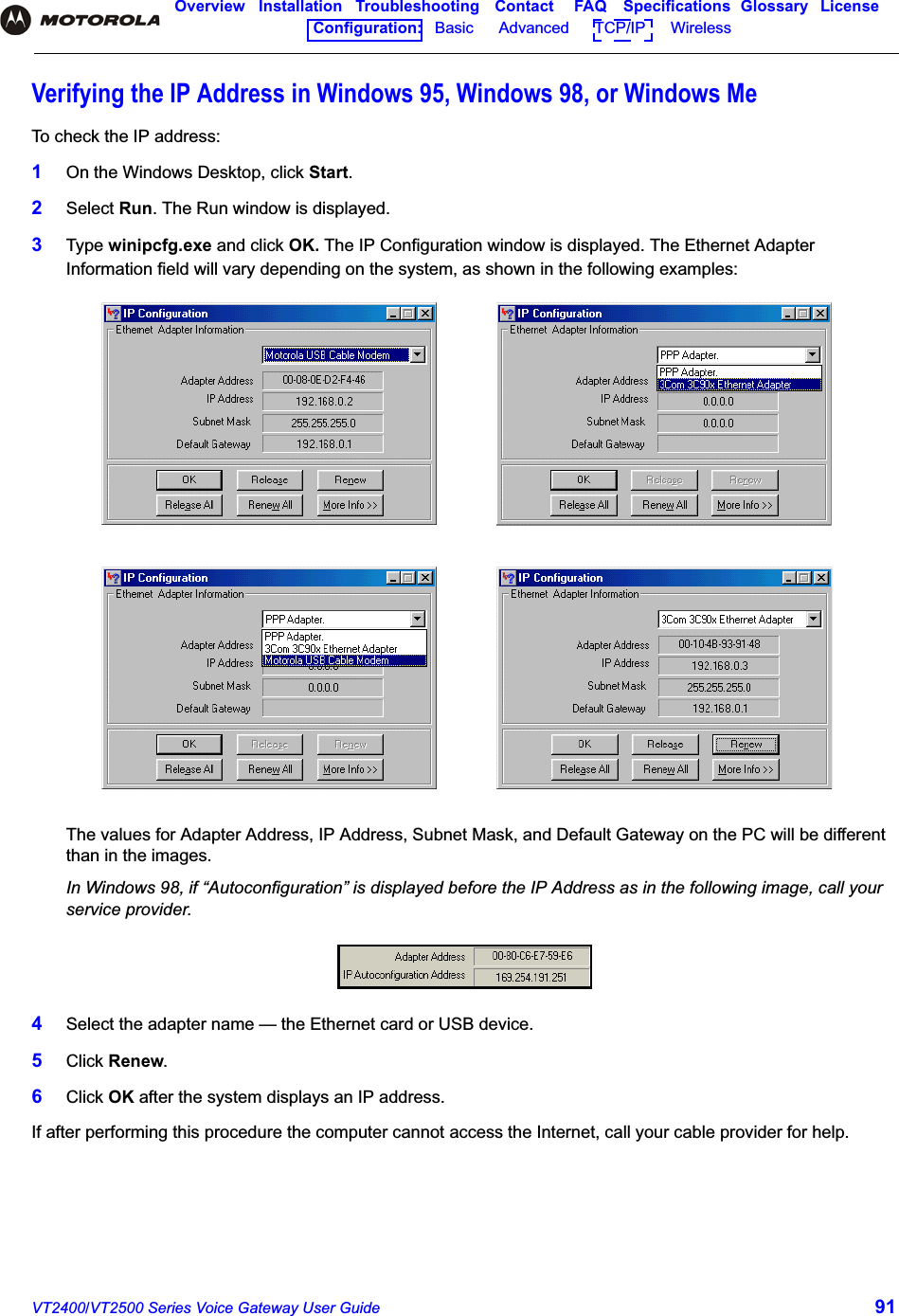
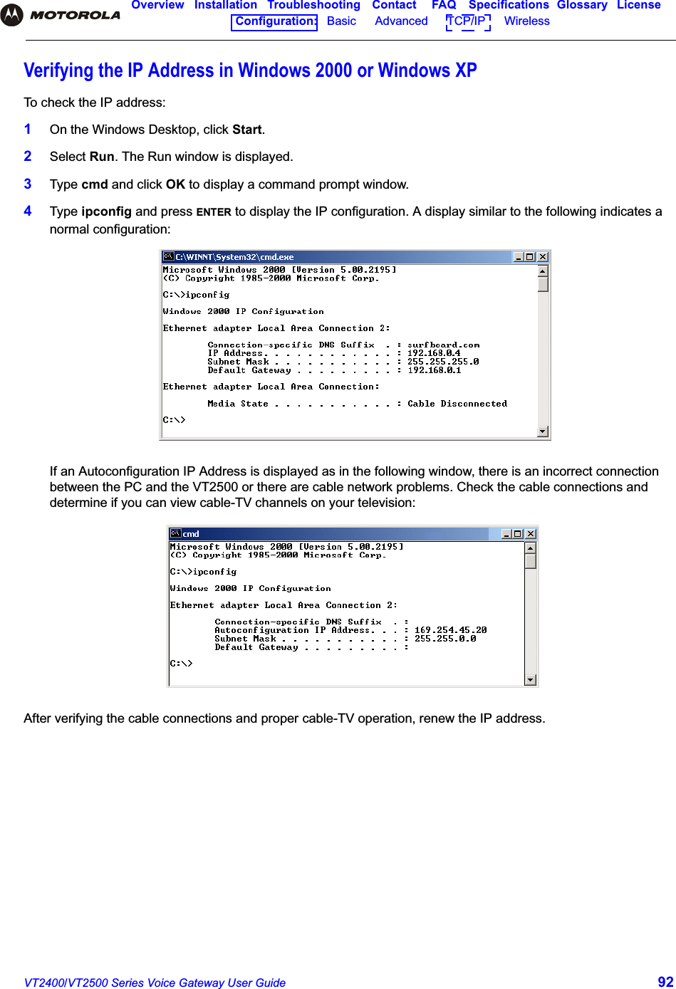
>
ARRIS
>
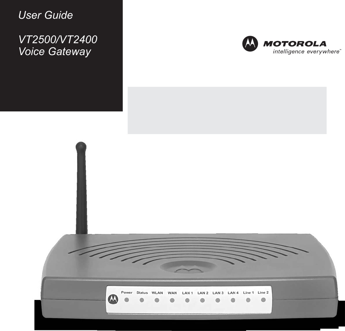
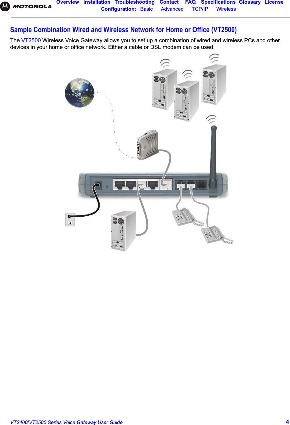
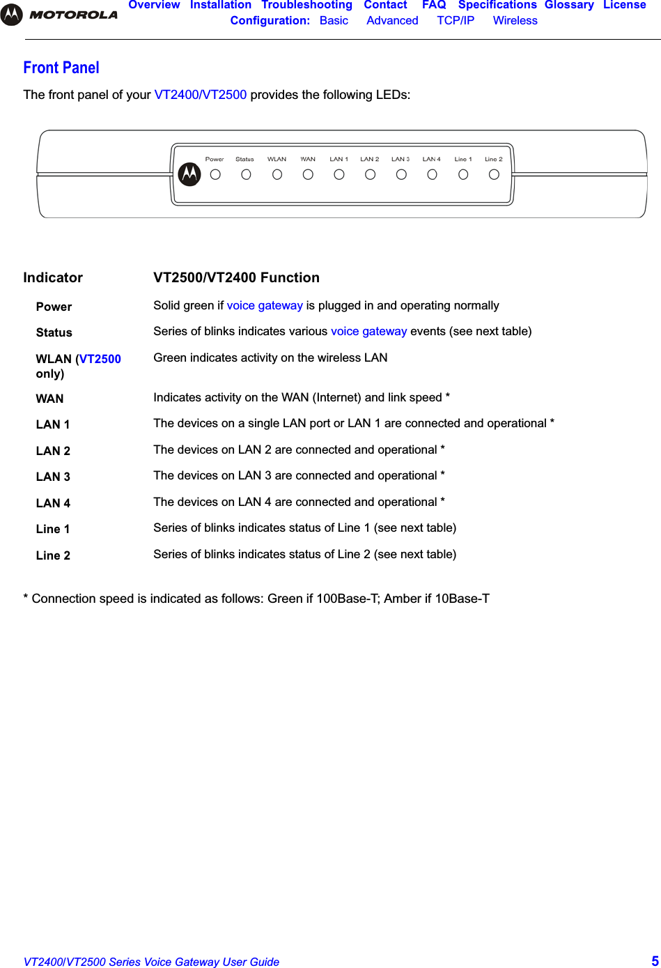
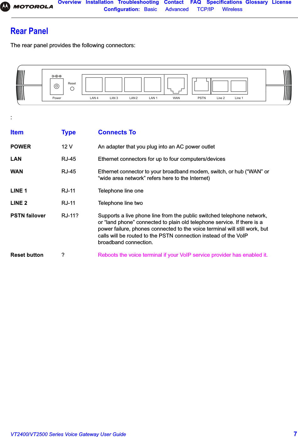
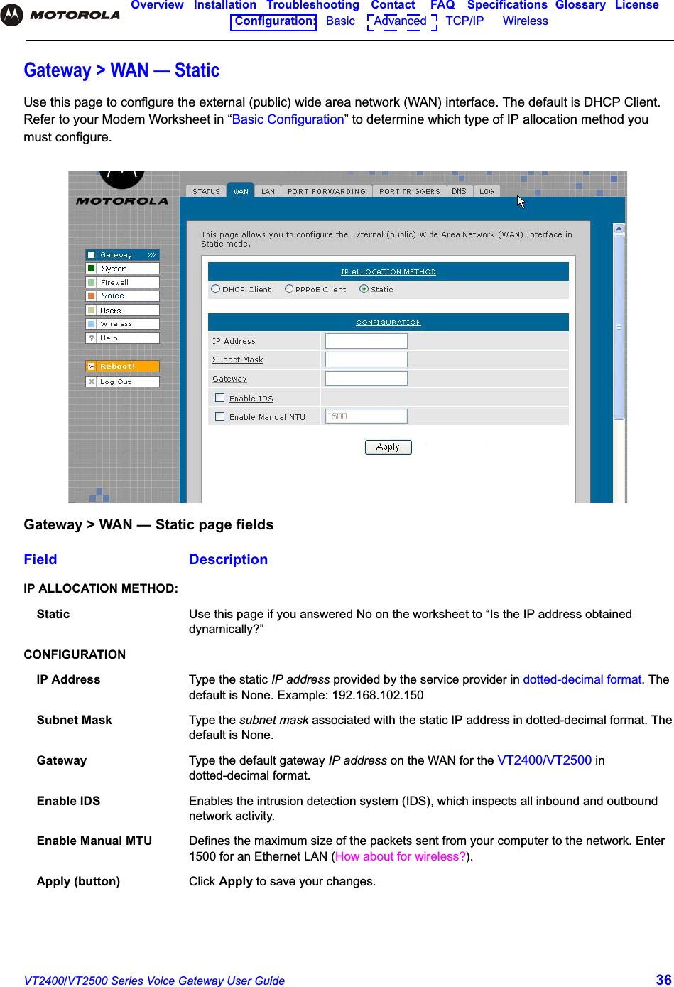
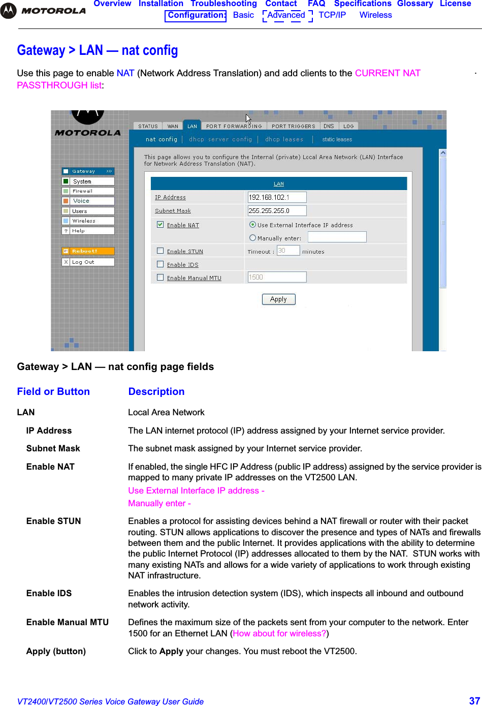
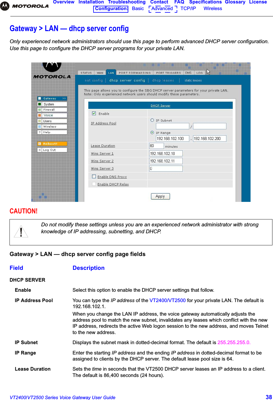
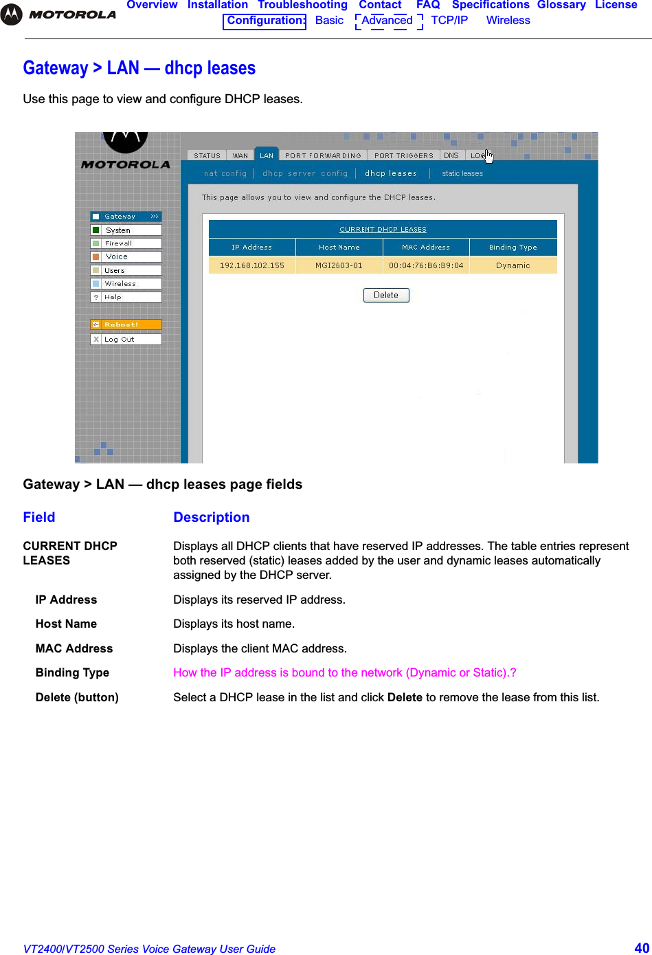
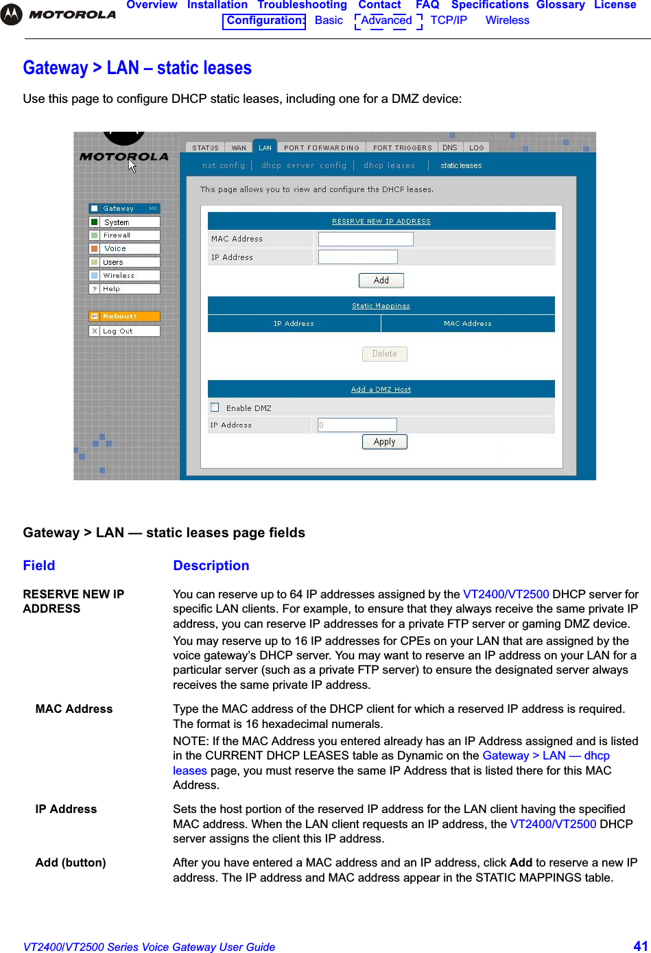
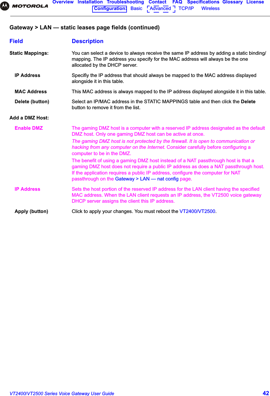
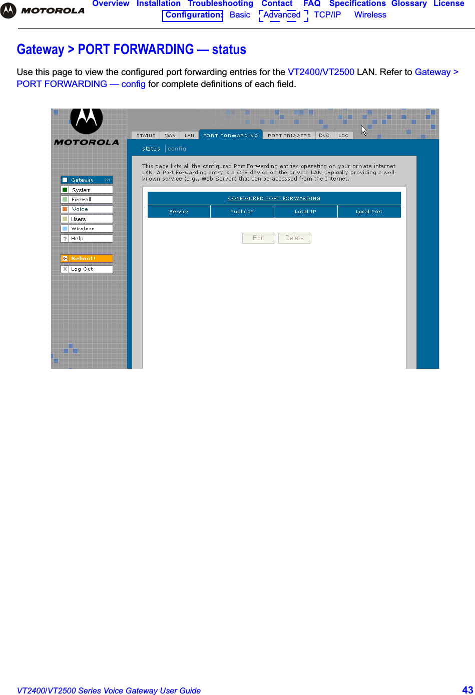
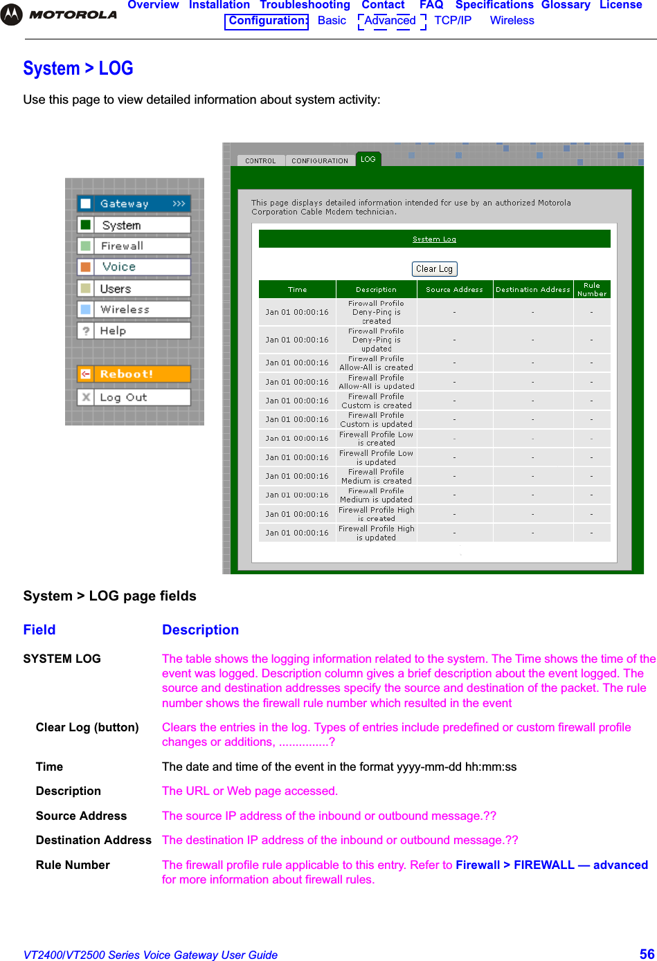
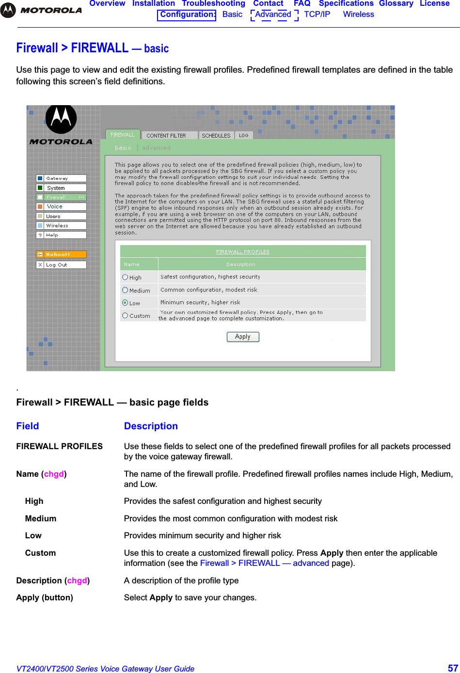
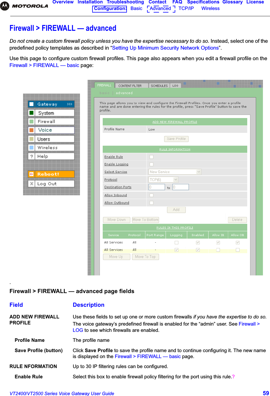
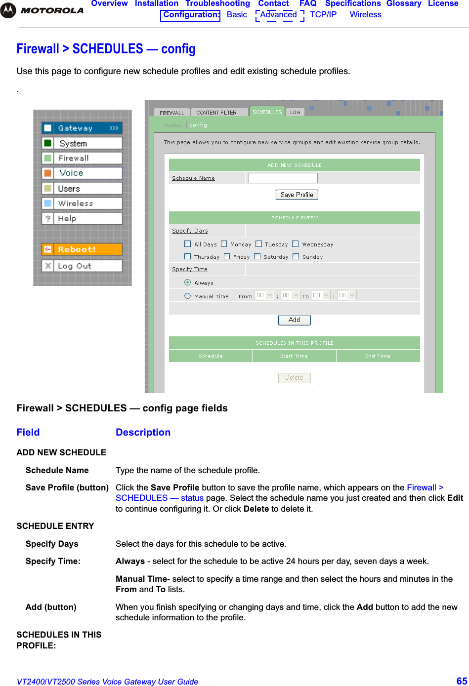
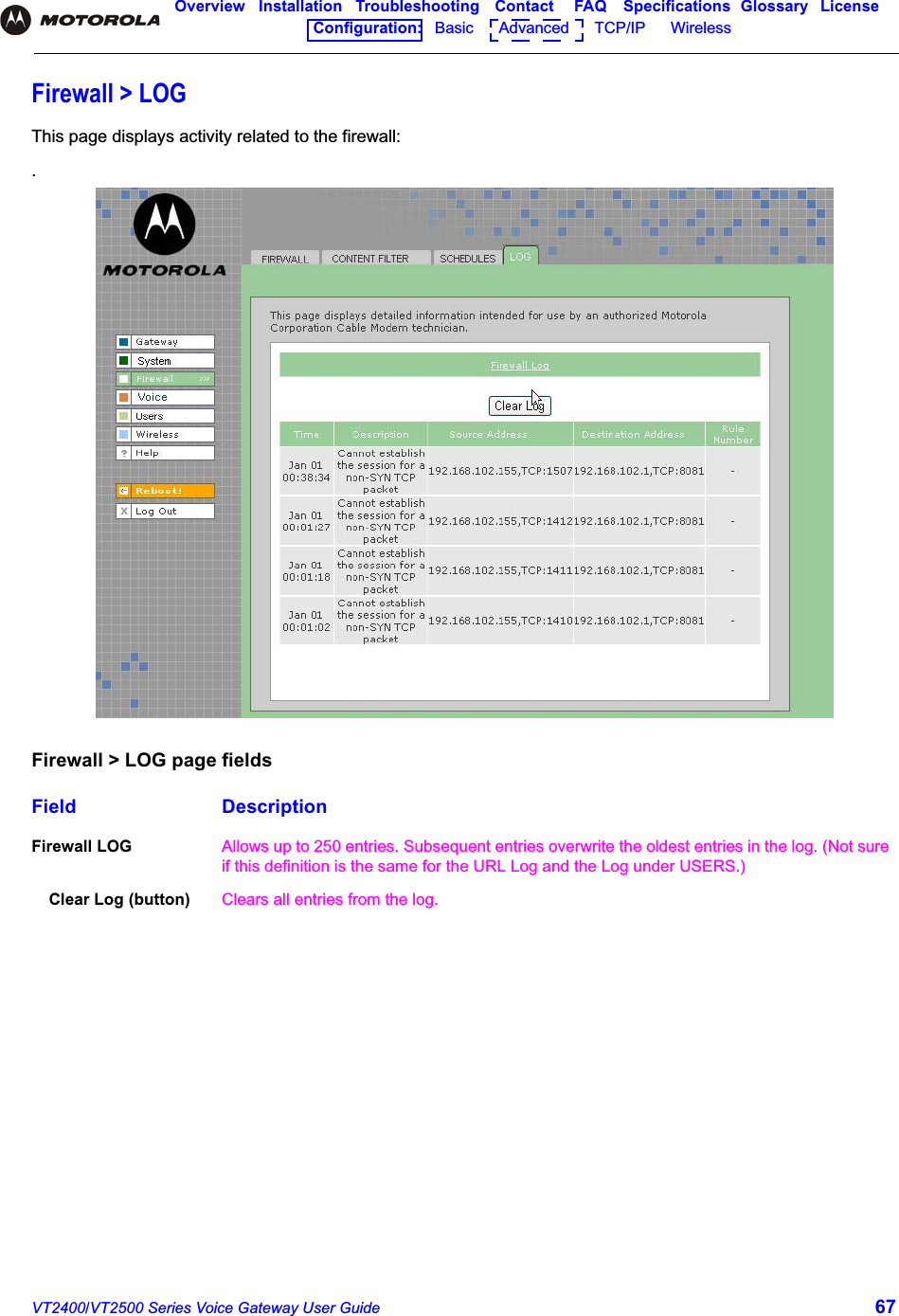
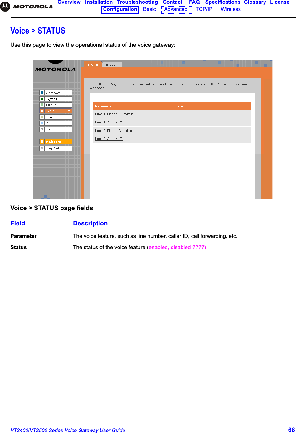
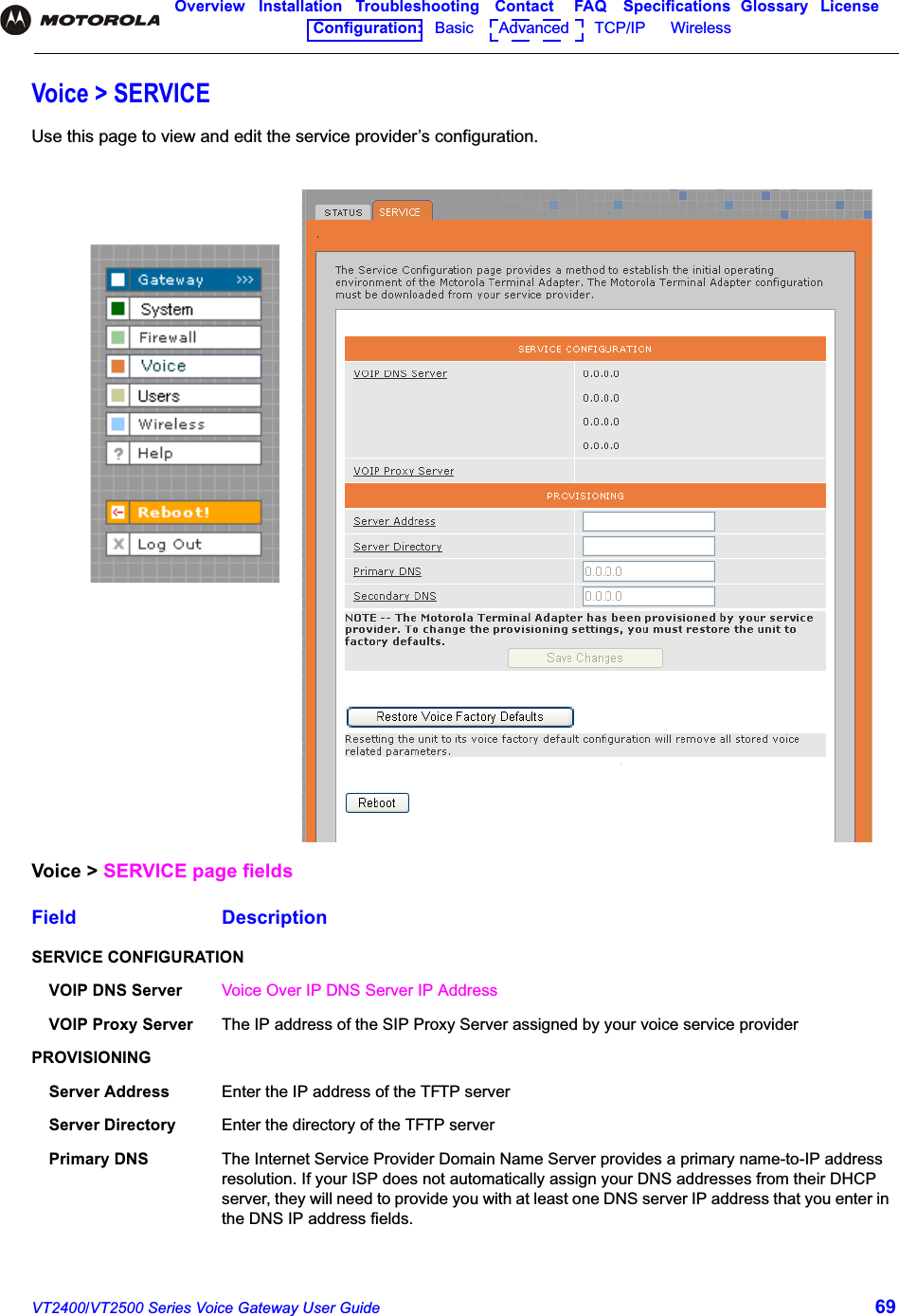
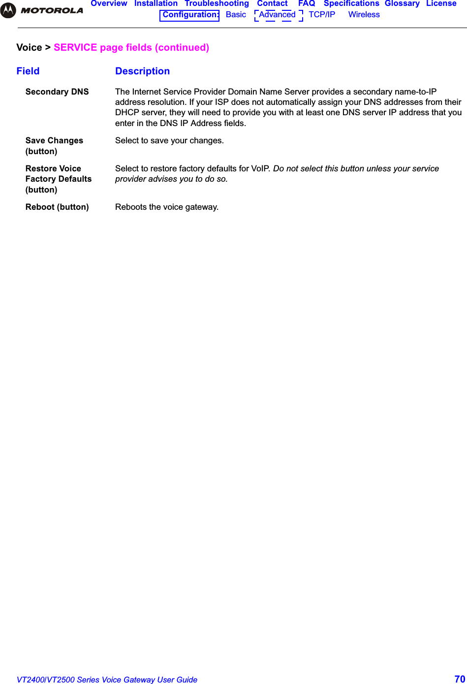
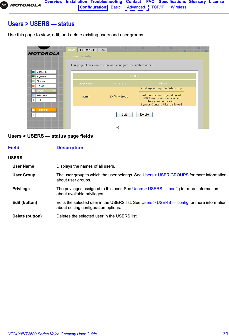
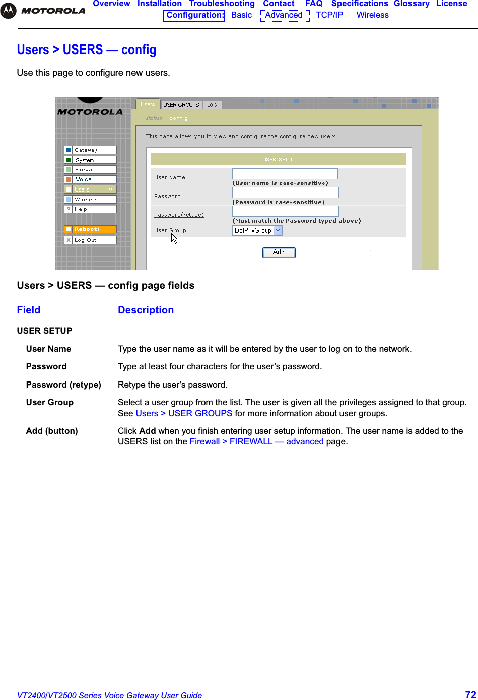
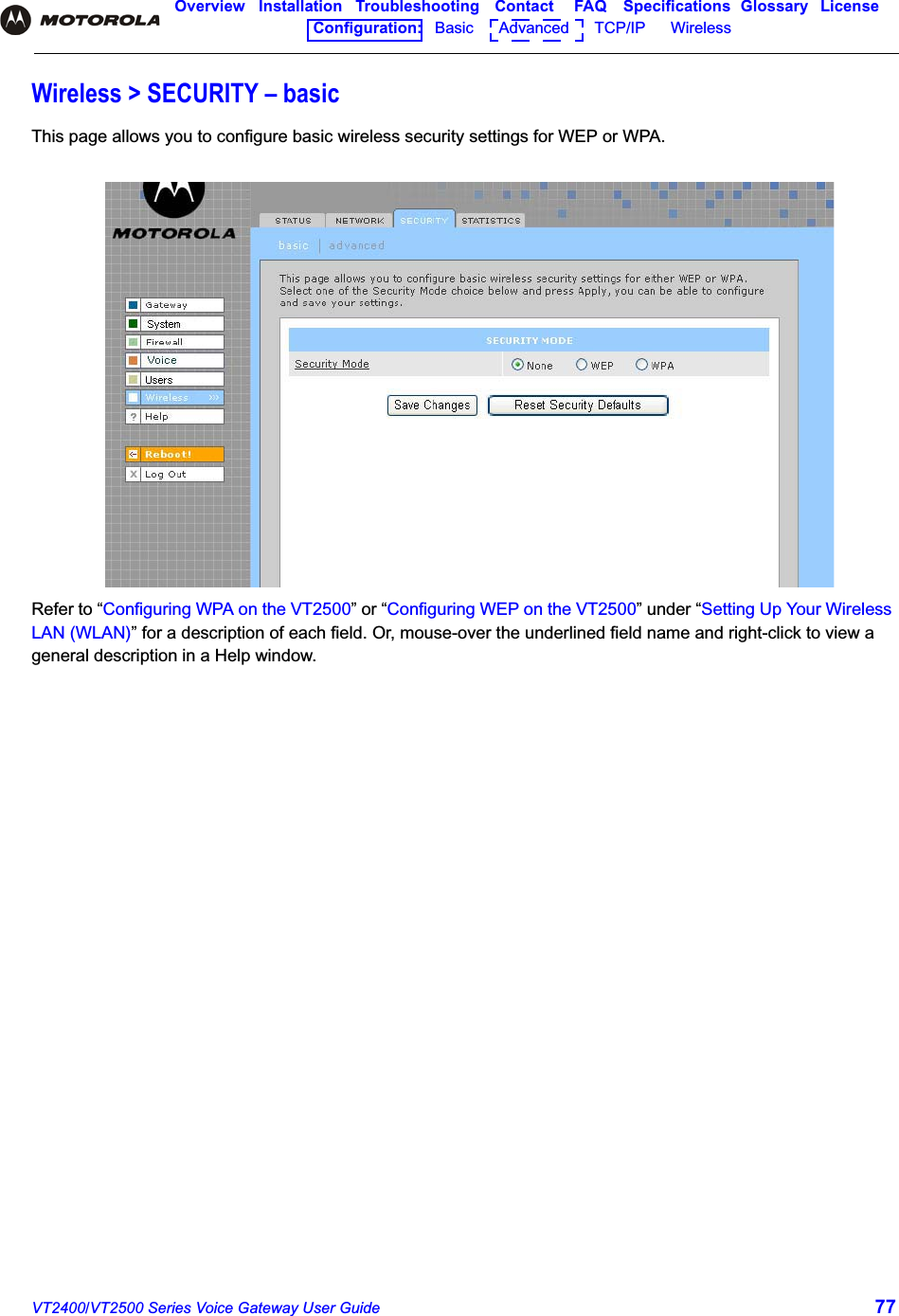
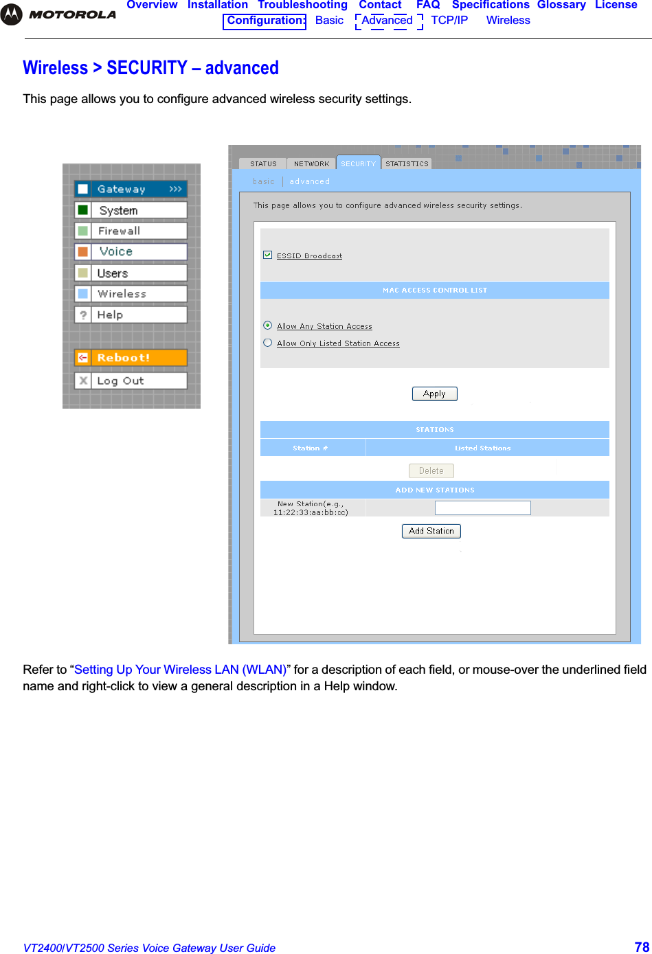
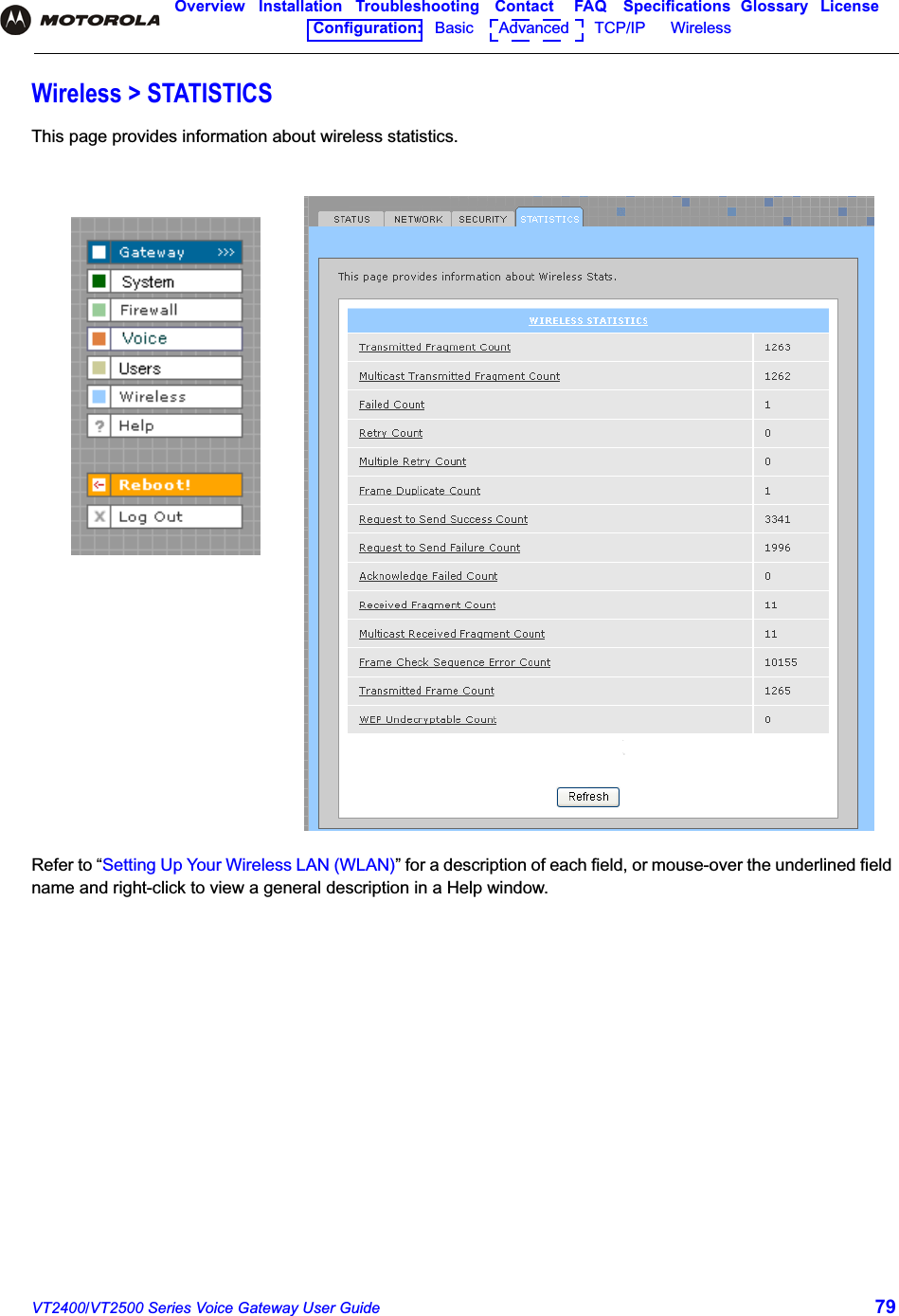
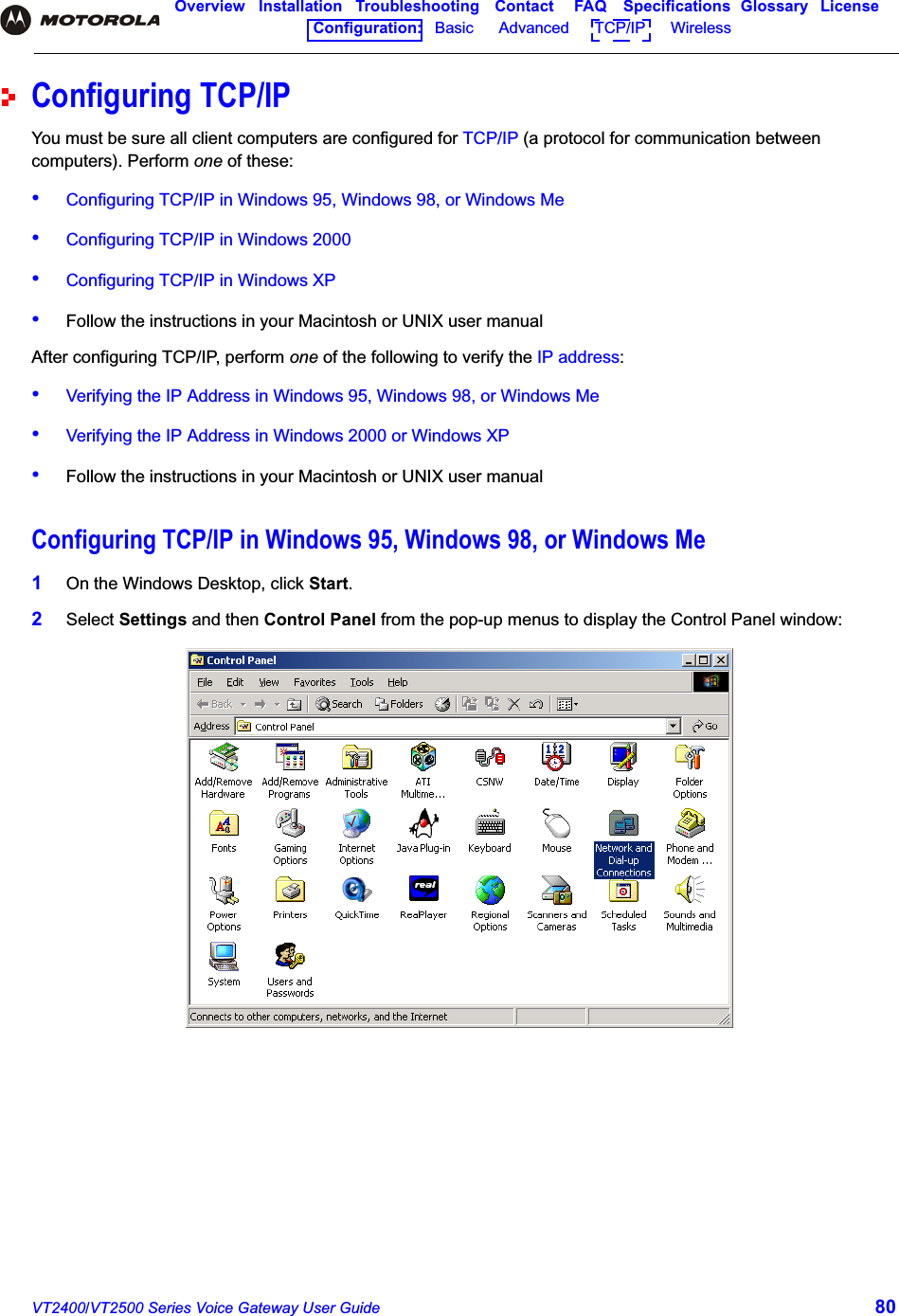
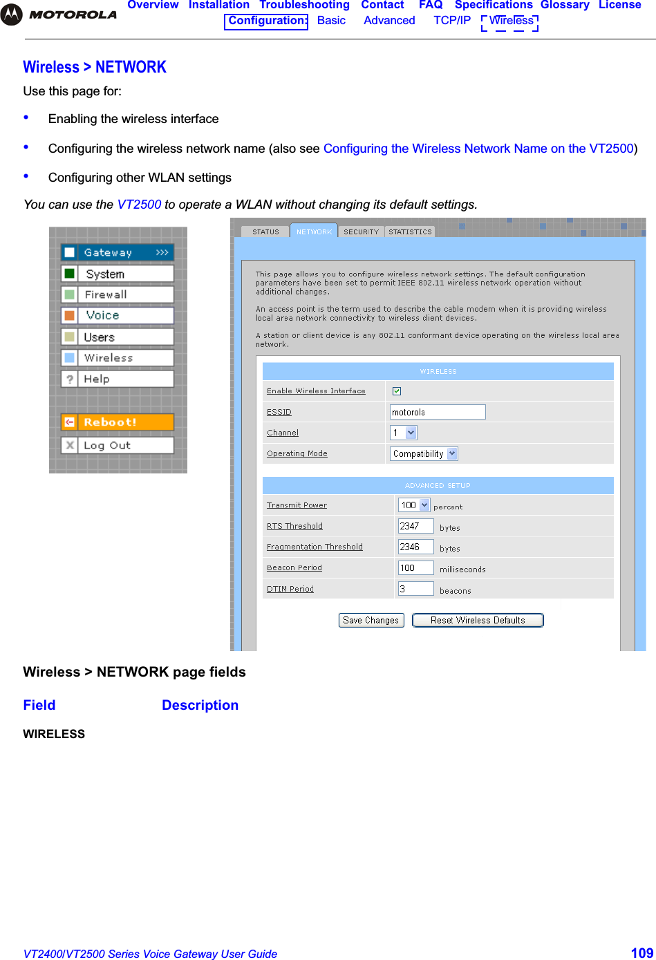
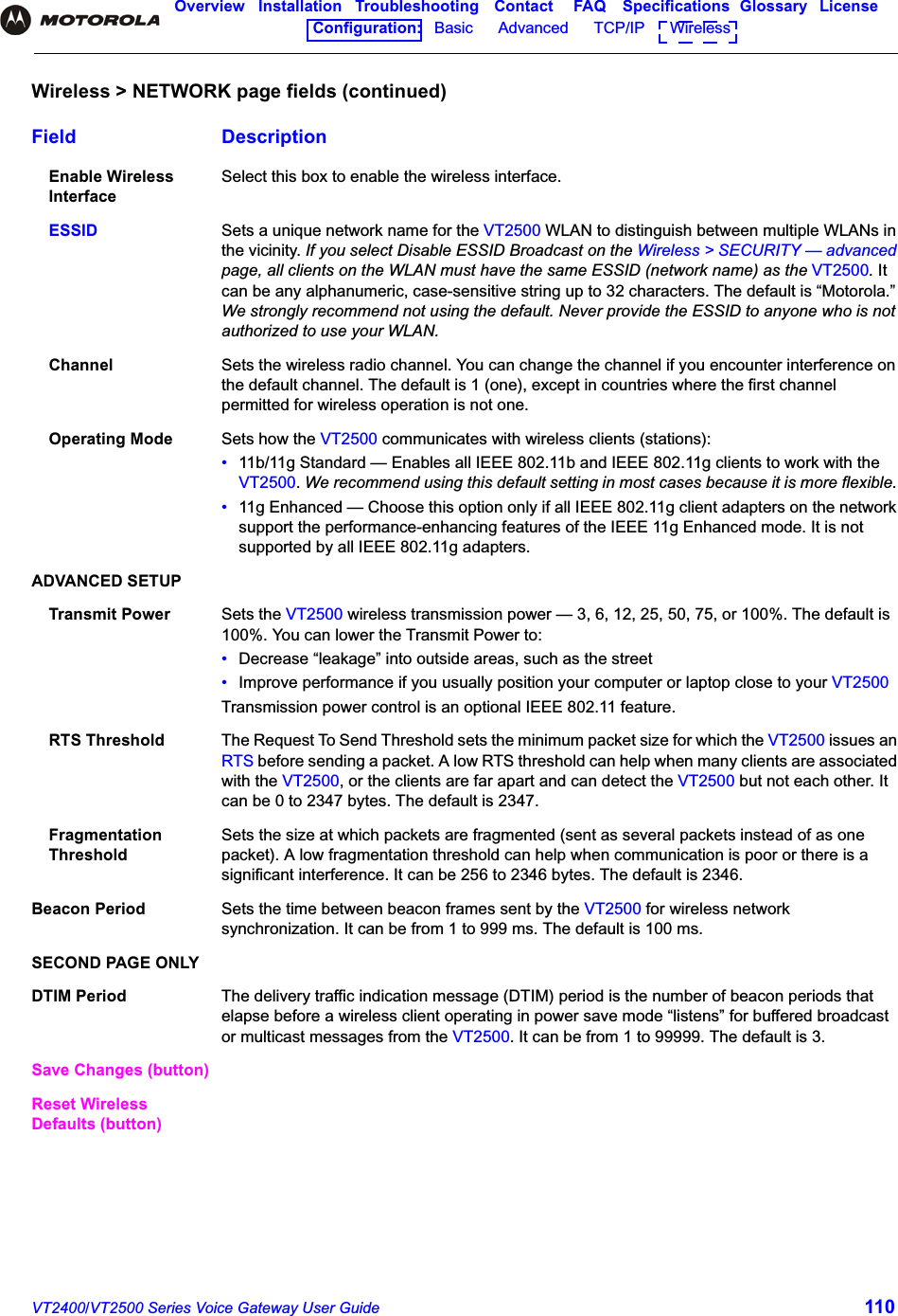
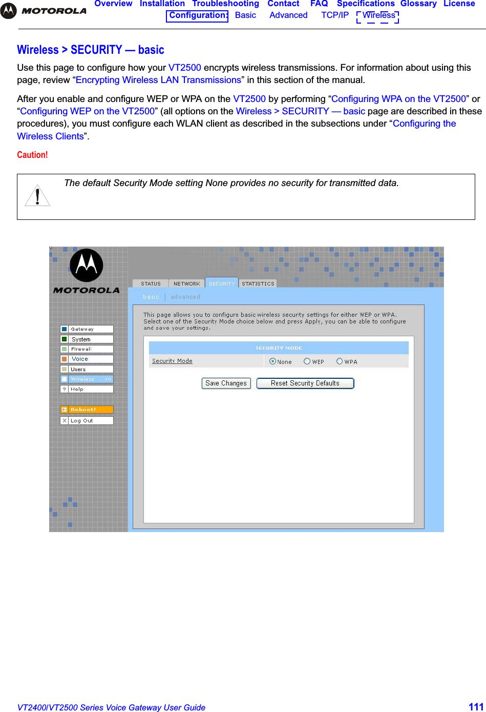
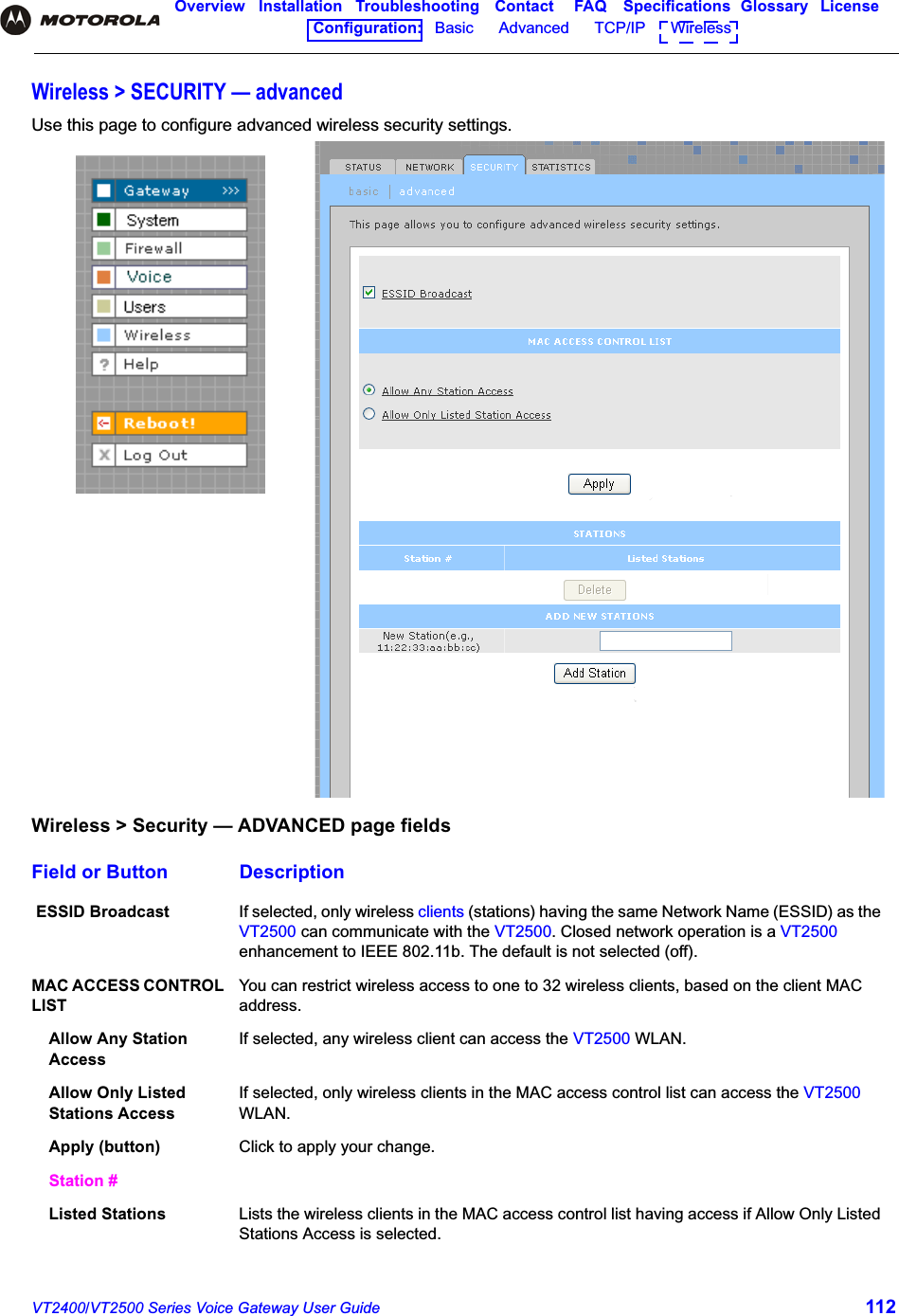
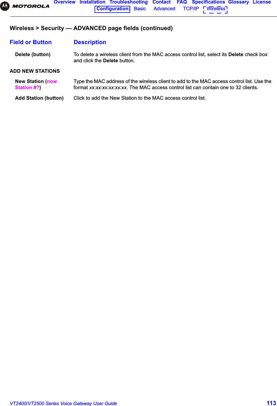
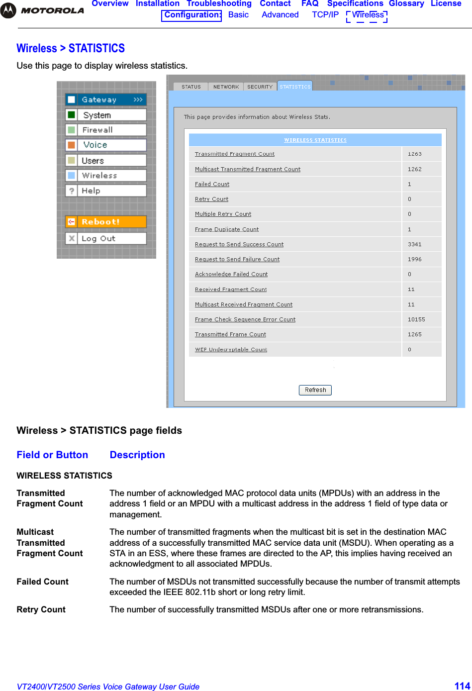
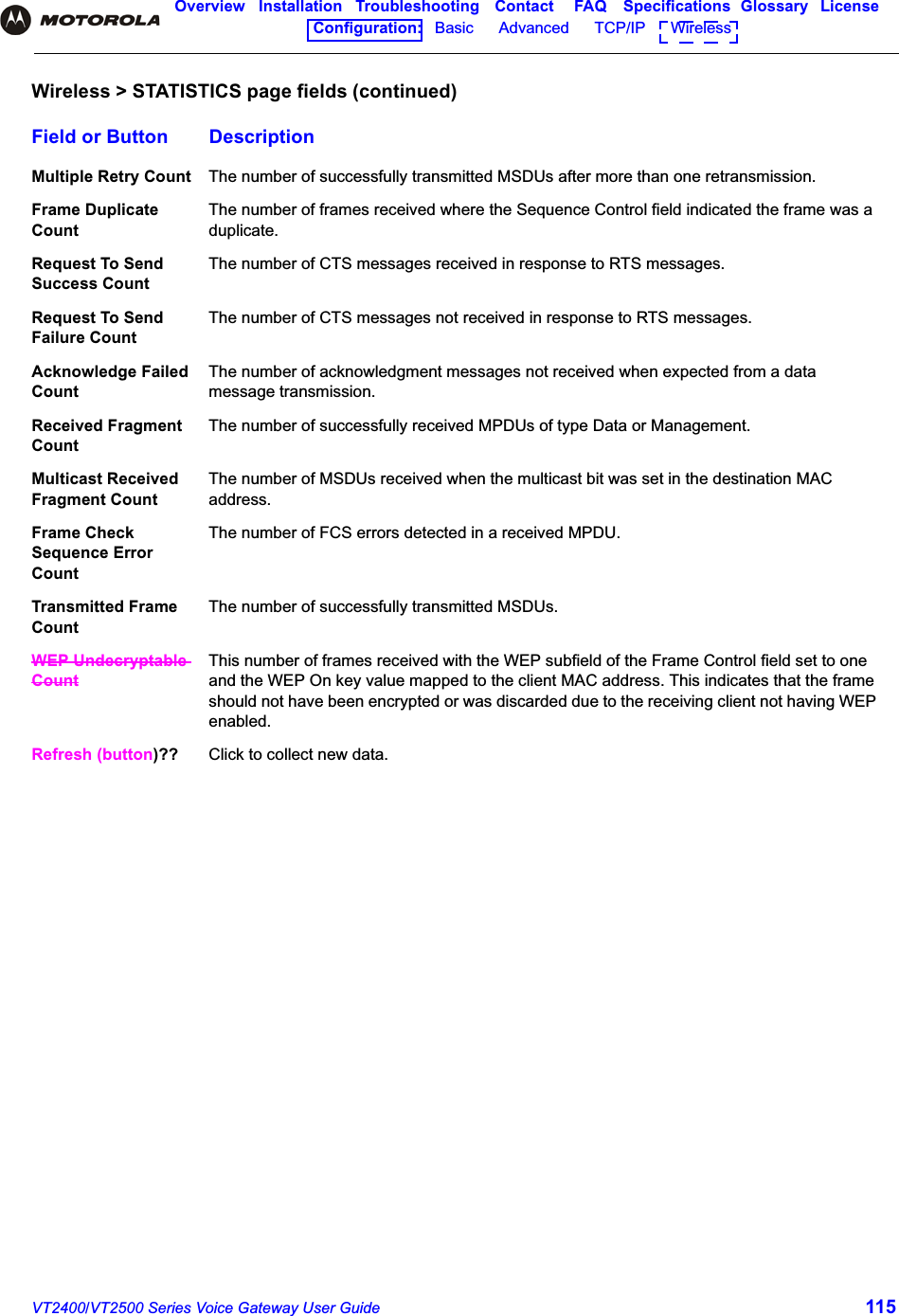
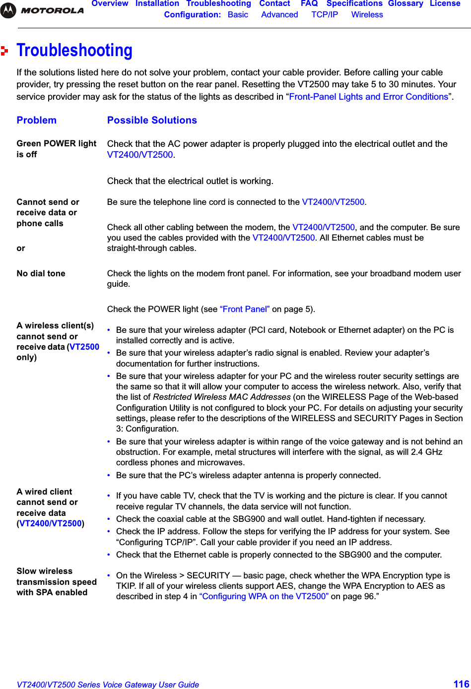
VT2500 User Manual
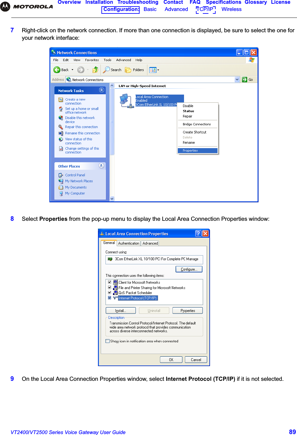
Users Manual
Navigation menu
Upload a User Manual
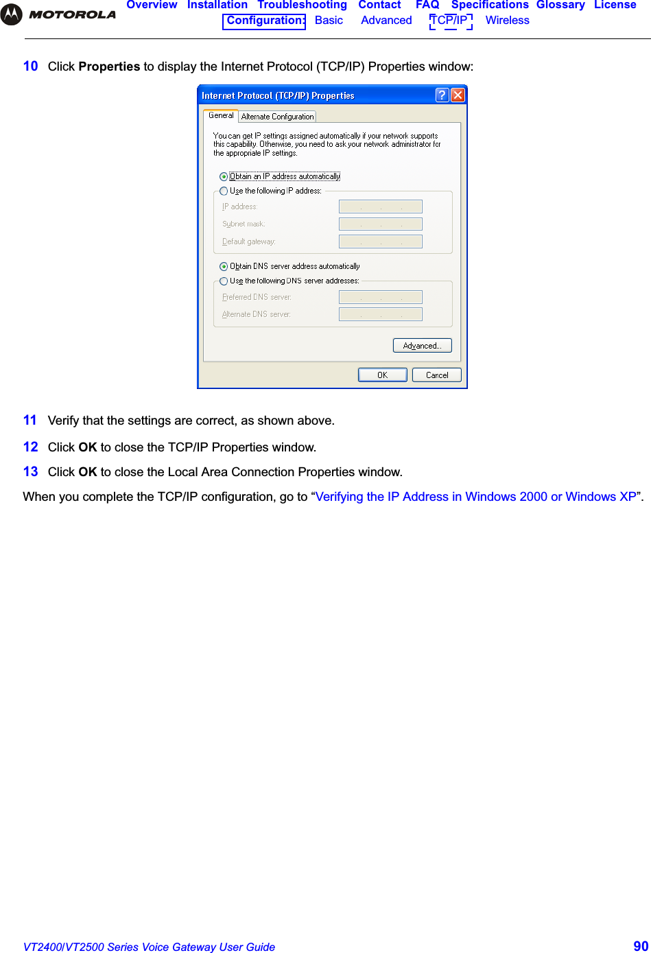
Namespaces
Wiki Guide
HTML
PDF
Info
Views
User Manual
Discussion / Help
Navigation