ARRIS WVB2R0-34 Wireless Gateway User Manual DRAFT WVB2 Manual
ARRIS Group, Inc. Wireless Gateway DRAFT WVB2 Manual
UserManual.wiki
>
ARRIS
>
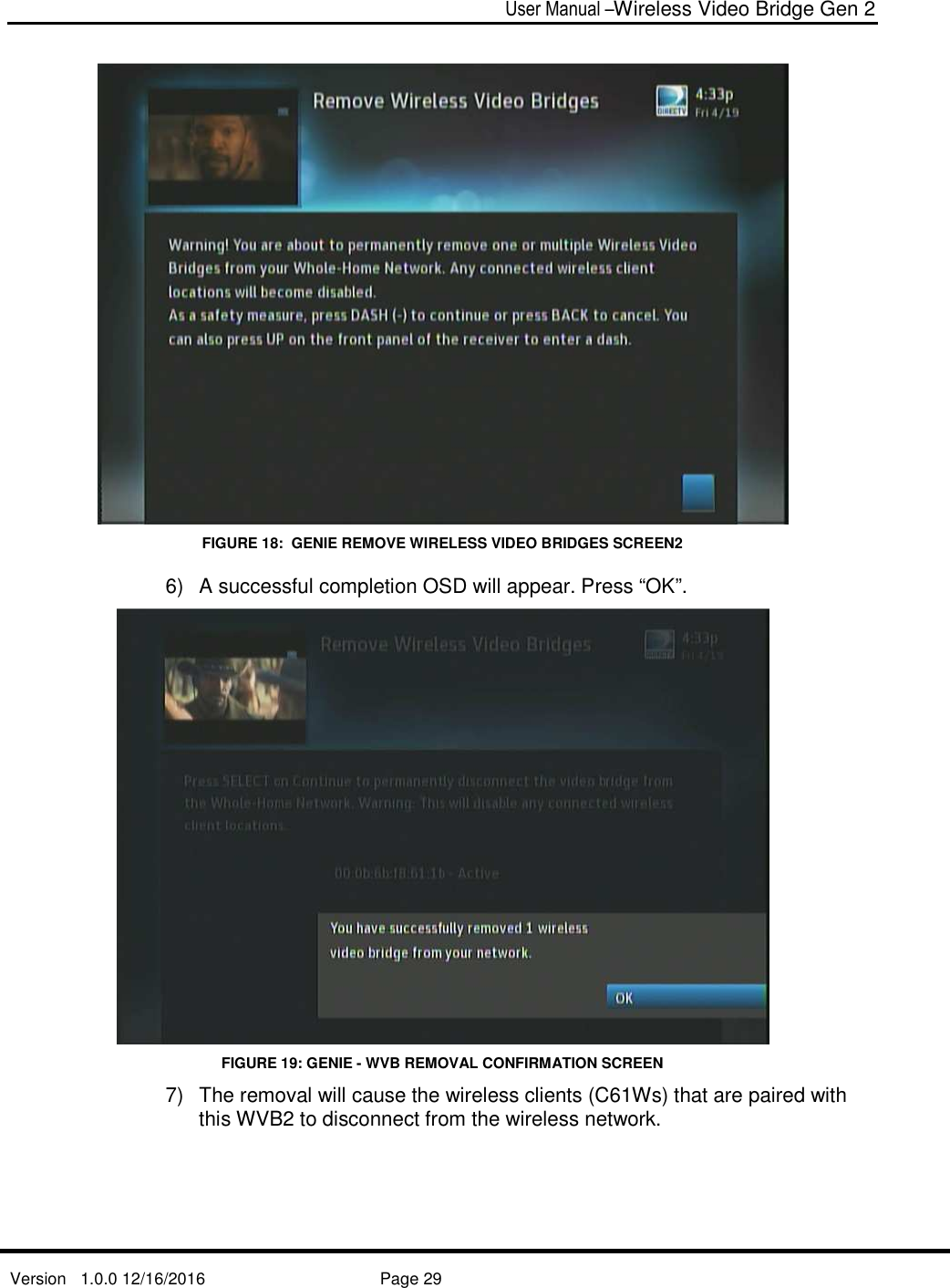
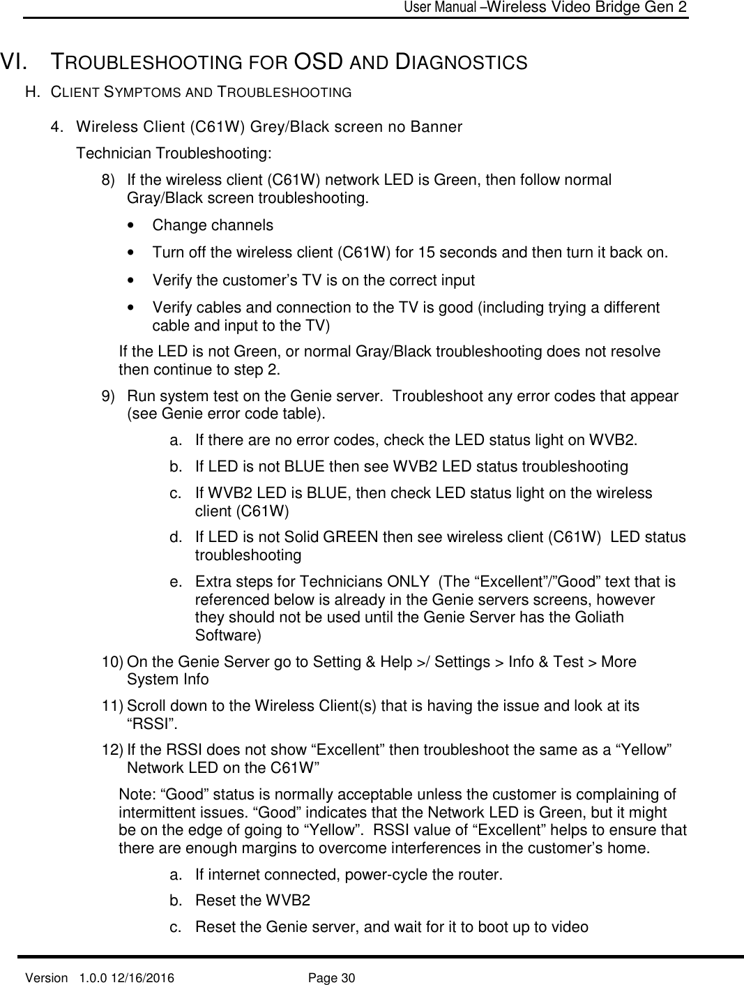
WVB2R0 34 User Manual
User Manual
Navigation menu
Upload a User Manual
Namespaces
Wiki Guide
HTML
PDF
Info
Views
User Manual
Discussion / Help
Navigation