ARRIS WVB2R0-34 Wireless Gateway User Manual DRAFT WVB2 Manual
ARRIS Group, Inc. Wireless Gateway DRAFT WVB2 Manual
ARRIS >
User Manual

User Manual –Wireless Video Bridge Gen 2
Version 1.0.0 12/16/2016 Page i
U
SER
M
ANUAL
W
IRELESS
V
IDEO
D
ISTRIBUTION
W
IRELESS
V
IDEO
B
RIDGE
G
EN
2
REVISION HISTORY
Date
Author
Description of Change
Version
December 16, 2016
Alexander Fitch First Draft 0.0.1
Engineering
Release
January 4
th
Alexander Fitch Add Wall Mount instructions and FCC statements 0.0.2
Engineering
Release
The purpose of this document is to communicate the technical information associated with the
C61W and Wireless Video Bridge Gen2, and to provide an overview addressing how the new
capabilities may impact the customer, agent and field technician.

User Manual –Wireless Video Bridge Gen 2
Version 1.0.0 12/16/2016 Page ii
C
ONTENTS
I. Overview ........................................................................................................................... 6
A. Wireless Video Bridge ................................................................................................. 6
II. Hardware Information ........................................................................................................ 7
A. Wireless Video Bridge ................................................................................................. 7
1. Front Panel ............................................................................................................ 7
2. Rear Panel ............................................................................................................. 7
3. The rear panel contains ......................................................................................... 8
III. Minimum Requirements ....................................................................................................11
IV. Features ...........................................................................................................................12
A. 802.11ac Support. ......................................................................................................12
B. MoCA 2.0 ...................................................................................................................12
C. Wireless Repeater Functionality .................................................................................12
D. Wireless Protected Setup ...........................................................................................12
V. Installation ........................................................................................................................14
A. How the Wireless Video Bridge Works .......................................................................14
B. Installation Requirements ...........................................................................................14
1. Minimum Distances ..............................................................................................15
2. Maximum Distances..............................................................................................15
3. Wall Mount Installation ..........................................................................................16
C. Wireless Video Bridge Survey (aka Beacon Mode) .....................................................17
D. WVB Installation .........................................................................................................19
E. Adding Wireless Clients (C61W) .................................................................................20
F. Final Checks ...............................................................................................................24
G. Remove WVB2 from the Genie Server .......................................................................26
VI. Troubleshooting for OSD and Diagnostics ........................................................................30
H. Client Symptoms and Troubleshooting .......................................................................30
4. Wireless Client (C61W) Grey/Black screen no Banner ..........................................30
5. C61W Program Banner displayed, no Video on TV ..............................................33
6. C61W Video/Audio on TV but no Menu, Guide or List displays .............................33
7. Freeze Frame/Pixelization on wireless client (C61W) ...........................................33
8. C61W does not display the Enter PIN screen .......................................................33
9. Wireless client (C61W): Add a Client failed (does not display video after Add a
Client exited) ..............................................................................................................33
10. Wireless Client (C61W) Network LED Failures (Bad Wireless Connection) ..........33
I. OSD Troubleshooting .................................................................................................35

User Manual –Wireless Video Bridge Gen 2
Version 1.0.0 12/16/2016 Page iii
11. Genie server OSD: ...............................................................................................35
12. Wireless Client (C61W) OSD: ...............................................................................35
13. Wireless Client (C61W) OSD: ...............................................................................36
14. Wireless Client (C61W) OSD: ...............................................................................36
15. Wireless Client (C61W) OSD: ...............................................................................36
J. Genie Server Error Code Table ..................................................................................37
VII. Other Troubleshooting ......................................................................................................39
K. WVB2 LED Troubleshooting .......................................................................................39
L. Wireless Client C61W Troubleshooting ......................................................................41
VIII. FCC Statements ...............................................................................................................44

User Manual –Wireless Video Bridge Gen 2
Version 1.0.0 12/16/2016 Page iv
FIGURES
Figure 1: WVB2 - Front Panel ................................................................................................... 7
Figure 2: WVB2 - Rear Panel .................................................................................................... 8
Figure 3 : Side View with new logo ............................................................................................. 9

User Manual –Wireless Video Bridge Gen 2
Version 1.0.0 12/16/2016 Page v
TERMINOLOGY
Term
Description
WVB Wireless Video Bridge

User Manual –Wireless Video Bridge Gen 2
Version 1.0.0 12/16/2016 Page 6
I. O
VERVIEW
The Wireless Video Bridge Technical Communication will cover all the aspects of Wireless
Video and the Wireless Video Bridge.
A. W
IRELESS
V
IDEO
B
RIDGE
The WVB Gen2 is a second generation Wireless Video Bridge that is targeted as a direct
replacement to the WVB Gen1 with enhanced networking features.
The Wireless Video Bridge (WVB2) provides the ability to stream DIRECTV programming
from a Genie server to the Genie Mini (C41W or higher) client wirelessly.
The Wireless Video Bridge provides video distribution throughout the home without the use
of coaxial or CAT5 cables at every TV. The WVB2 creates a private network only accessible
to DIRECTV products.
User Manual –Wireless Video Bridge Gen 2
Version 1.0.0 12/16/2016 Page 7
II. H
ARDWARE
I
NFORMATION
A. W
IRELESS
V
IDEO
B
RIDGE
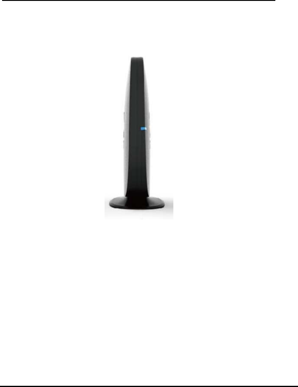
1. Front Panel
FIGURE 1: WVB - FRONT PANEL
The front panel contains
• Multicolor status indicator LED.
The WVB2 is to be installed vertically (It is not to be placed in horizontal position)
The WVB2 can be wall-mounted using the mounting bracket provided. When using the
mounting bracket, the WVB2 should remain positioned upright (not upside down).
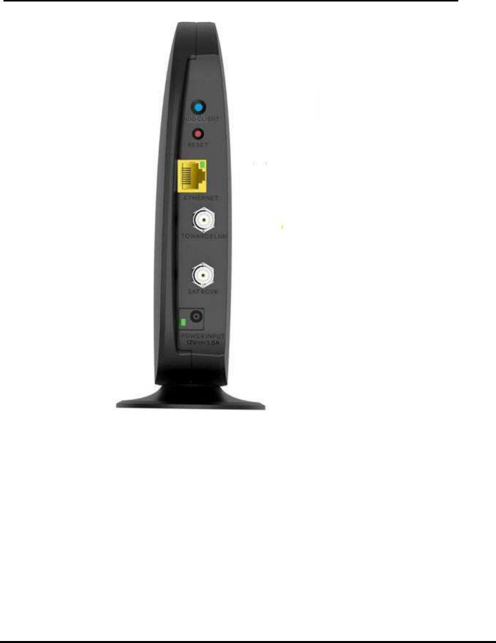
2. Rear Panel
User Manual –Wireless Video Bridge Gen 2
Version 1.0.0 12/16/2016 Page 8
FIGURE 2: WVB - REAR PANEL
3. The rear panel contains
• Red reset button
• Add Client button
• Ethernet port
• Two Satellite in F connector
• DC power Inlet connector matching EPS10 external Power supply
• A green power indicator LED.
User Manual –Wireless Video Bridge Gen 2
Version 1.0.0 12/16/2016 Page 9
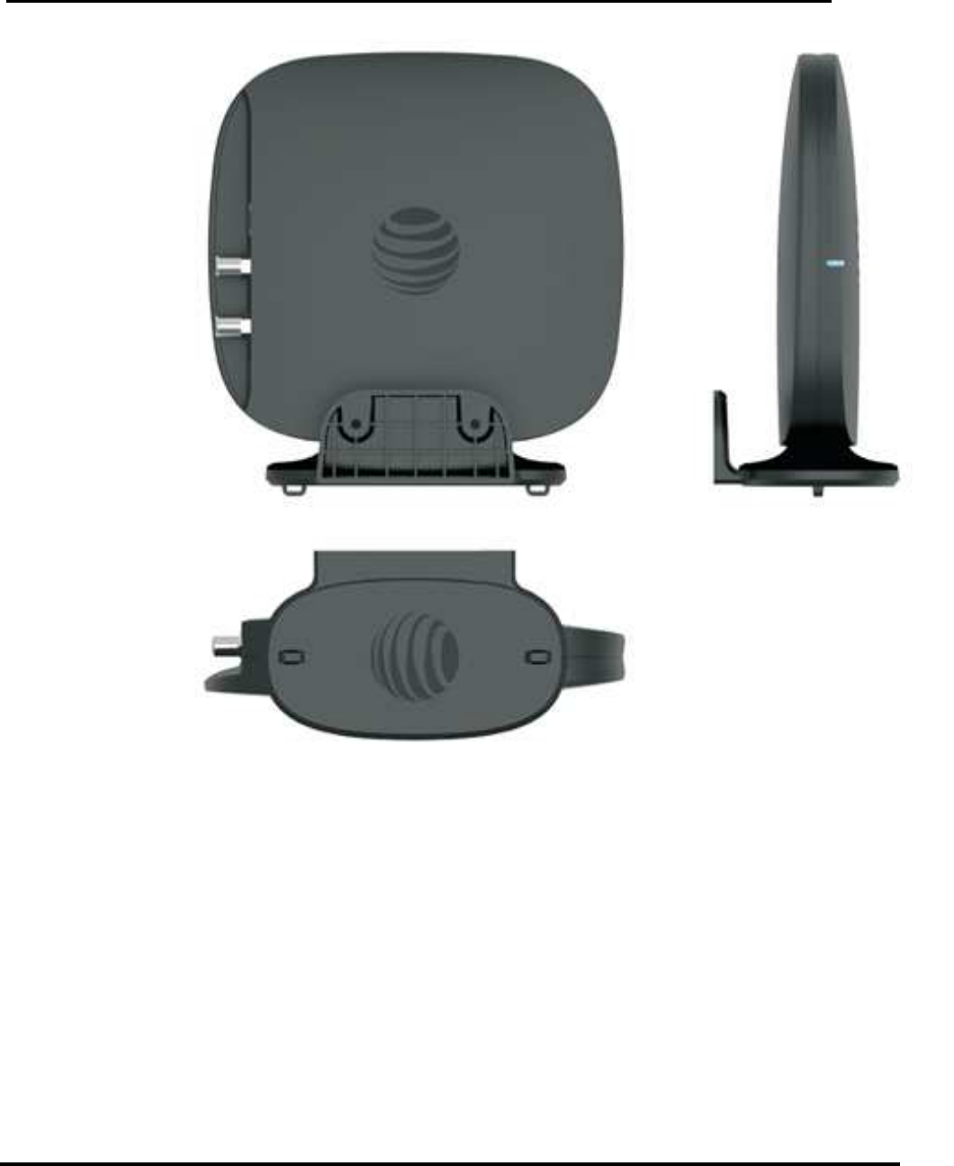
FIGURE 3 : SIDE VIEW WITH NEW LOGO

User Manual –Wireless Video Bridge Gen 2
Version 1.0.0 12/16/2016 Page 10
WVB2 Specifications
Size and Weight
• Height: 182”
• Width: 190”
• Depth 182”
• Weight: 12.05 oz.
Packaging
• Carton
• Height: 10.25”
• Width: 4”
• Depth: 9”
• Weight: 2 lb.
Environmental Requirements
• Operating temperature:32° to 122°
F (0° to 50° C) for indoor units
• Storage temperature (No Damage):
-40° to 150° F ( -40° to 66° C)
• Relative humidity: 93% non-
condensing
Ports and Interfaces
• 802.11n,ac Wi-Fi
• Coax Network SWiM input
• Coax Network SWiM output
• DC Power Input
• Inactive Ethernet Port
Power
• EPS10 External PSU
• AC external PSU -120v~60HZ, 18W
• Input: 12V DC 1.5A
• Active Current Consumption (DC) :
1.0A – 1.2A

User Manual –Wireless Video Bridge Gen 2
Version 1.0.0 12/16/2016 Page 11
III. M
INIMUM
R
EQUIREMENTS
The minimum requirements for a Wireless Video distribution are
• SWiM installation
• Genie server (HR34/HR44/HR54/H44+HDD)
• Wireless Video Bridge
• At least one wireless Genie Mini Client

User Manual –Wireless Video Bridge Gen 2
Version 1.0.0 12/16/2016 Page 12
IV. F
EATURES
Functionally, the WVB Gen2 is identical to the WVB Gen1 with the exception of the following
features:
A. 802.11
AC
S
UPPORT
.
802.11ac is the latest IEEE Wi-Fi standard which provides increased bandwidth and
additional throughput over increased range compared to 802.11n (on which WVB Gen 1 is
based). Increased throughput is required to sustain the level of video traffic required to
support more concurrent clients which are a feature of the HS17family of products with up to
7 HD clients supported or 2 Wireless 4K Clients and one Wireless HD client.
B. M
O
CA
2.0
MoCA 2.0 allows for increased frequency range and channel bandwidth, which leads to
increased throughput over greater distances in comparison to MoCA 1.1. MoCA 2.0 is also
backwards compatible with MoCA 1.1 and will therefore allow for operability with existing,
MoCA 1.1 compliant products.
C. W
IRELESS
R
EPEATER
F
UNCTIONALITY
The WVB Gen2’s ability to act as a wireless repeater indicates that the WVB Gen2 will offer
a wireless solution for extending the range of the internal WVB of the HS17
D. W
IRELESS
P
ROTECTED
S
ETUP
The WVB Gen 2 will contain an Add Client Button that will primarily be used with the HS17
eliminating the need to add the RVU Client through the “Add Client” Screen. If the user
chooses, they also have the option of adding a RVU client through the “Add Client” screen
just like the WVB Gen 1.
Feature Comparison between the WVB Gen1 and the WVB Gen2

User Manual –Wireless Video Bridge Gen 2
Version 1.0.0 12/16/2016 Page 13
Feature
WVB Gen1
WVB Gen2
MoCA
1.1 2.0
Wireless
802.11n 802.11n, ac
Ethernet
Yes (10/100) Yes (10/100/1G)
F Connectors (female F
-
type)
2 2
Reset Button
Yes Yes
Power LED
Yes Yes
Status LED
Yes Yes
Mechanicals (mm)
190x182x82 190x182x82
Weight (oz)
12.5 12.5
Power Supply
EPS10 EPS10
DFS Channel Support
Yes Yes
Maximum Supported Number of Clients
3 5
Wi
-
Fi Band Operation
5GHz 5GHz
Minimum Throughput Over 3 Streams
72Mbps 120Mbps
WVB
Range
80 feet, 5 walls 80 feet, 5 walls
MIMO Solution
4x4 4x4
DTV WPS Button
No Yes
VA SNE Compliant
No Yes
Feature
WVB Gen1
WVB Gen2
Bridge MoCA to Wi
-
Fi Traffic
Yes Yes
Wireless Repeater Functionality
No Yes
User Manual –Wireless Video Bridge Gen 2
Version 1.0.0 12/16/2016 Page 14
V. I
NSTALLATION
A. H
OW THE
W
IRELESS
V
IDEO
B
RIDGE
W
ORKS
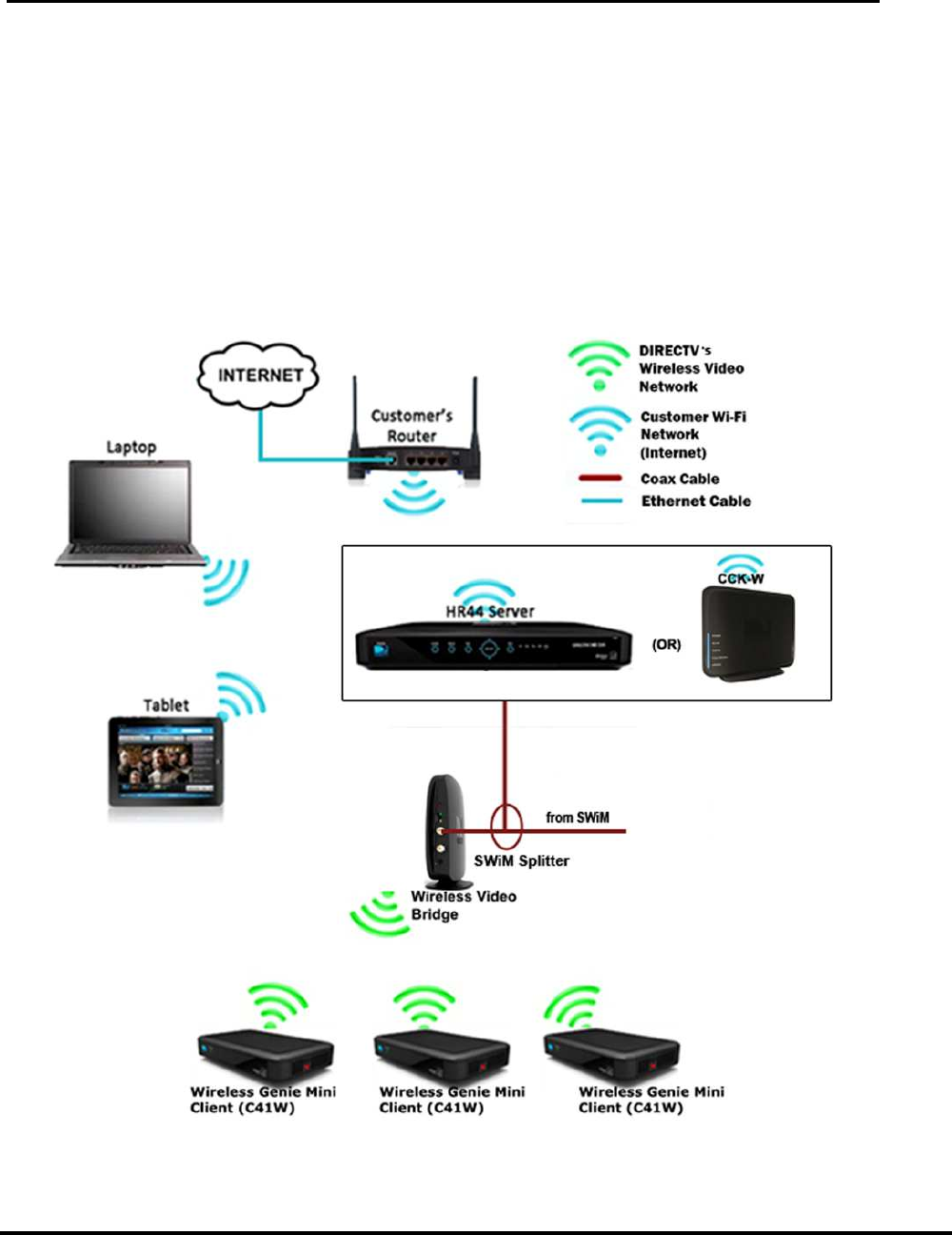
• The Wireless Video Bridge Gen 2 (WVB2) is connected to the Genie server via the
SWiM/MoCA network.
• The WVB2 acts as an access point for the C61W, creating the Wireless Video Network
for wireless clients (C61W).
• The WVB2 delivers audio/video and the user interface wirelessly to the clients as if there
was a traditional coax network in the home, and this connection is different and separate
from the Wi-Fi connection to the customers Router.
FIGURE 4: WI-FI & DIRECTV’S WIRELESS VIDEO NETWORK DIFFERENCES (NEW DIAGRAM)
B. I
NSTALLATION
R
EQUIREMENTS
Version 1.0.0 12/16/2016
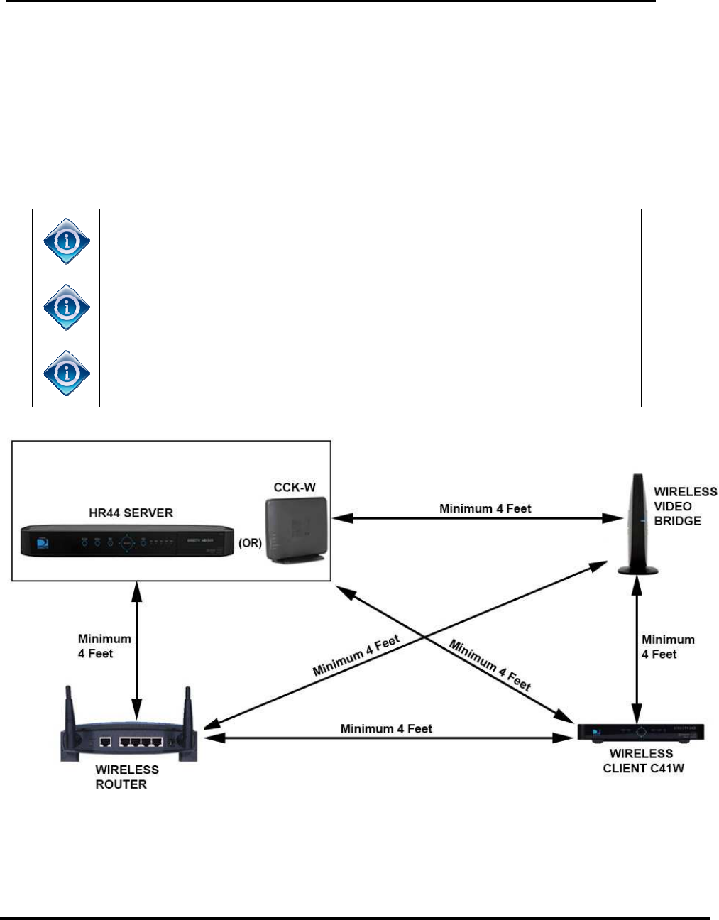
1. Minimum Distances
•
The wireless devices
risk of interference.
• HR54 or CCK-
W and WVB2 must be a minimum of
• HR54 or CCK-
W
•
Wireless router and WVB
• WVB
2 and Wireless Client (C6
Distance
is physical distance NOT the length of the cable.
Concrete, Brick, Stone or other high density material can
the wireless signal
For proper placement of Genie, WVB
Wireless
Video Bridge
2. Maximum Distances
User Manual –
Wireless Video Bridge Gen 2
Page 15
The wireless devices
require a minimum distance between
each other
risk of interference.
The following are the required distances.
W and WVB2 must be a minimum of
4 feet apart
W
and Wireless Router
must be a minimum of
Wireless router and WVB
2 must be a minimum of
4 feet apart
2 and Wireless Client (C6
1W) must be a minimum of 4 feet apart
is physical distance NOT the length of the cable.
Concrete, Brick, Stone or other high density material can
limit the
the wireless signal
For proper placement of Genie, WVB
2
, Wireless Clients and Router a
Video Bridge
Survey should be performed.
FIGURE 5: MINIMUM DISTANCES DIAGRAM
Wireless Video Bridge Gen 2
each other
to decrease
4 feet apart
must be a minimum of
4 feet apart
4 feet apart
1W) must be a minimum of 4 feet apart
limit the
range for
, Wireless Clients and Router a

User Manual –Wireless Video Bridge Gen 2
Version 1.0.0 12/16/2016 Page 16
The WVB2 and the Wireless Client (C41W, C61W) should be placed no further than 80
feet apart and have no more than 5 internal walls between them. It is important to
recognize this is guidance and home construction will significantly decrease range.
Walls and other barriers can decrease the range and significantly impact the maximum
distances. Use signal strength to determine installation quality.
Below are examples of various barriers and how they degrade the signal and lower the
maximum distance from the WVB2.
Standard Medium Strong Extreme
• Plexiglas
• Sheet plywood
• Internal wall (2
layers drywall +
2”x4” studs)
• Fir lumber
• Non-stucco
external wall (wood
siding)
• Wood floor/ceiling
• Stucco wall (with
diamond metal
mesh)
• Brick/Stone
wall/fireplace
• Double-pane tinted
high efficiency
door/window
Metal objects
(ducting, appliance,
enclosure, television)
<5 dB signal loss 5-10 dB 10-20 dB >20 dB
No impact up to 5
barriers, 15 feet
distance impact for
each additional
barrier
30 feet distance
impact per barrier 45 feet distance
impact per barrier Potential link
breakage with solid
RED LED
Examples of operating range
• 65 feet with 5 internal walls + 1 standard barrier
• 50 feet with 5 internal walls + 1 medium barrier
• 35 feet with 5 internal walls + 1 strong barrier
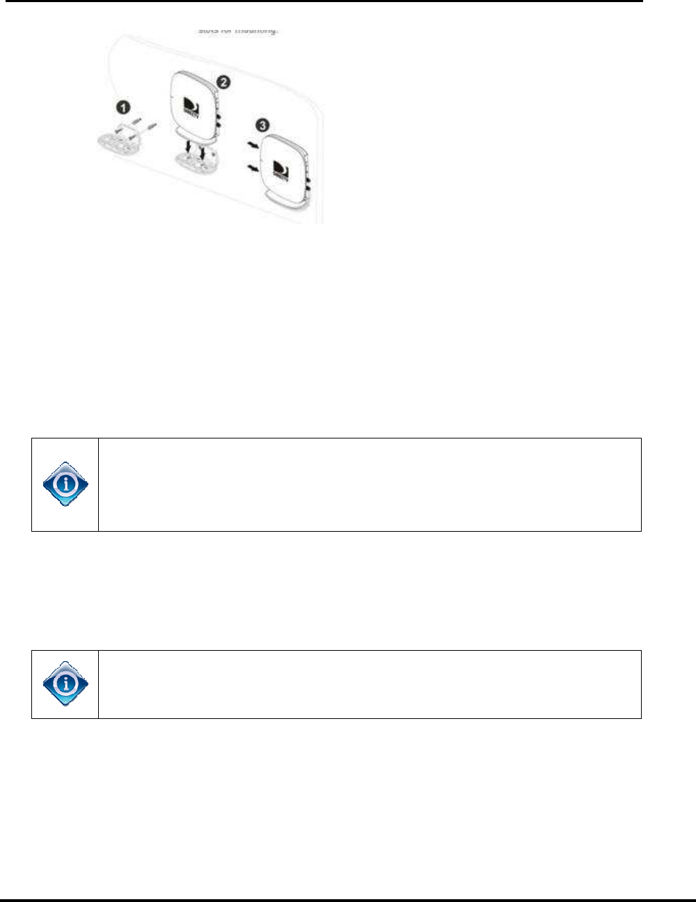
3. Wall Mount Installation
• Drive the screws through the mounting plate to be fastened and into the wall. (See
Step 1)
• Align the two slots at the bottom of the unit with the two pins on the mounting plate.
(See step 2)
• Slide them until they lock in place (See step 3)
Version 1.0.0 12/16/2016
C. W
IRELESS
V
IDEO
B
RIDGE
The WVB2
survey is important to determine placement of
clients (C6
1W). As part of the initial WVB survey, the technician determines a central
location to place the WVB
determining the following:
• D
etermine the Genie server (HR44/HR5
•
Determine the client locations
•
Determine the location of the WVB
The WVB2
must be installed in a vertical position using the permanently
attached foot/pedestal.
negative impact on the distance the clients can be from the WVB
Do not place the WVB
The following is the WVB
new installs and upgrades.
1)
The WVB
instructed.
2)
Setup the wireless clients (C6
If the C41W,
C6
to
its final mounted
WVB.
3)
Connect the wireless client (
wireless client (
Video Bridge” screen. (
“Continue” op
“Connect Now” option
they may proceed wi
•
If the client signal strength is poor, the Connect Now
disabled.
User Manual –
Wireless Video Bridge Gen 2
Page 17
RIDGE
S
URVEY
(
AKA
B
EACON
M
ODE
)
survey is important to determine placement of
the WVB2
1W). As part of the initial WVB survey, the technician determines a central
location to place the WVB
2 to service the Wireless Clients (C6
1Ws). This is done by
determining the following:
etermine the Genie server (HR44/HR5
4) location
Determine the client locations
Determine the location of the WVB
2.
must be installed in a vertical position using the permanently
attached foot/pedestal.
If the WVB2
is lying flat on its side, it can have a
negative impact on the distance the clients can be from the WVB
Do not place the WVB
2
on the floor as it may be easily knocked on its side.
The following is the WVB
2
survey/Beacon mode procedure. This procedure covers both
new installs and upgrades.
The WVB
2
is not to be connected to the SWiM/MoCA network
instructed.
Setup the wireless clients (C6
1W) in the location they will be used.
C6
1W is to be mounted behind the TV,
it should be placed
its final mounted
position as possible to fully verify signal quality
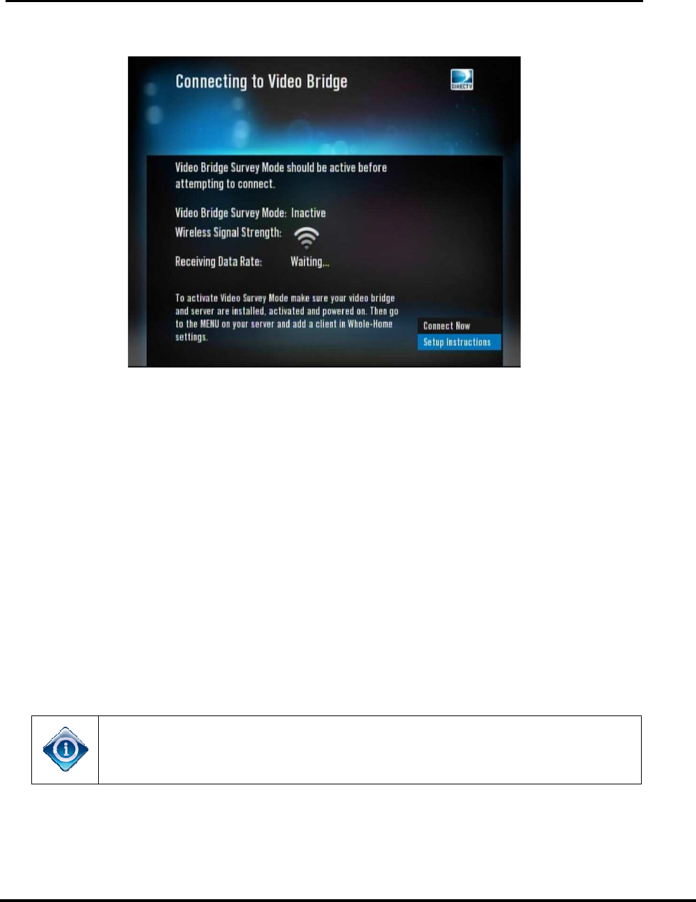
Connect the wireless client (
C41W, C6
1W) to the TV and p
wireless client (
C41W, C61W) will boot up to
the following “Connecting to
Video Bridge” screen. (
C41W, C6
1W with older software will have a
“Continue” op
tion, and C41W or C6
1Ws with new software will have a
“Connect Now” option
). The user need not wait for this screen to display;
they may proceed wi
th the next step.
If the client signal strength is poor, the Connect Now
/Continue
Wireless Video Bridge Gen 2
the WVB2
and Wireless
1W). As part of the initial WVB survey, the technician determines a central
1Ws). This is done by
must be installed in a vertical position using the permanently
is lying flat on its side, it can have a
negative impact on the distance the clients can be from the WVB
2.
on the floor as it may be easily knocked on its side.
survey/Beacon mode procedure. This procedure covers both
is not to be connected to the SWiM/MoCA network
until
1W) in the location they will be used.
it should be placed
close
position as possible to fully verify signal quality
from the
1W) to the TV and p
ower on. The
the following “Connecting to
1W with older software will have a
1Ws with new software will have a
). The user need not wait for this screen to display;
/Continue
option is
Version 1.0.0 12/16/2016
•
If the user selects Setup Instructions the instructions screen is displayed.
4) Select
the placement for the WVB
Select a location for the WVB
•
Best location to provide GREE
(use 5 walls and 80 feet as the guide)
•
Access to the coax SWiM network. Do not connect the W
network yet.
5) Power
on the WVB
up to a state referred to as ‘Survey mode’ or
transmits a signal for
sequence is as follows:
• WVB2
LED
•
The boot up takes approximately two minutes.
•
Once boot up has completed, the WVB
• The WVB
2
Wireless Video Bridge S
that have not previously been paired (factory
reset to factory defaults.
6)
The signal strength on every wireless client (
checked by ensuring that the Network LED
User Manual –
Wireless Video Bridge Gen 2
Page 18
If the user selects Setup Instructions the instructions screen is displayed.
FIGURE 6: C41W SIGNAL STRENGTH SCREEN
the placement for the WVB
2
Select a location for the WVB
2
based on the following factors:
Best location to provide GREE
N LED to all wireless clients(
(use 5 walls and 80 feet as the guide)
Access to the coax SWiM network. Do not connect the W
network yet.
on the WVB
2
and observe the power up sequence.
up to a state referred to as ‘Survey mode’ or
‘
Beacon
transmits a signal for
wireless clients (C41W, C6
1W)
sequence is as follows:
LED
flashes BLUE during boot up.
The boot up takes approximately two minutes.
Once boot up has completed, the WVB
2
LED alternates GREEN/YELLOW.
2
is now in Video Bridge Survey/Beacon
mode.
Wireless Video Bridge S
urvey/Beacon
mode works only on WVB
that have not previously been paired (factory
fresh
) or client
reset to factory defaults.
The signal strength on every wireless client (
C41W,
C
checked by ensuring that the Network LED
is GREEN
Wireless Video Bridge Gen 2
If the user selects Setup Instructions the instructions screen is displayed.
based on the following factors:
N LED to all wireless clients(
C41W, C61Ws)
Access to the coax SWiM network. Do not connect the W
VB2 to the coax
and observe the power up sequence.
The WVB boots
Beacon
Mode’ where it
1W)
. The WVB boot
LED alternates GREEN/YELLOW.
mode.
mode works only on WVB
2 and clients
) or client
s that have been
C
61W) should be
is GREEN

User Manual –Wireless Video Bridge Gen 2
Version 1.0.0 12/16/2016 Page 19
• If one or more of the wireless clients’ (C41W, C61W) network LED are not
green, the WVB2 will need to be relocated to an area that maximizes range
and minimizes interference. Refer to Troubleshooting section for more details.
• If more than one wireless clients (C41W, C61W) will be installed and a
GREEN LED cannot be achieved on all wireless clients (C41W, C61W) the
technician has the following options:
• Use a wired client (C41/C51/C61). Follow existing guidelines to install
the wired client if needed.
• Use more than one WVB2. Choose a location for the first WVB2 that
covers most of the wireless clients (C41W, C61W) and choose
another location for a second WVB2 to cover the wireless client(s)
(C61W) that have poor signal coverage.
7) Do not proceed if the signal strength is marginal (yellow network LED’s on
the wireless client (C61W(s)) A yellow network LED on the wireless client
(C61W) indicates poor signal strength to the WVB2. Consider moving the
WVB2, adding another WVB or using a wired client.
D. WVB
I
NSTALLATION
Once the WVB2 survey is complete and the optimal locations for the WVB2(s) and wireless
clients (C61W) have been determined, installation can begin.
1) If not previously performed, install the ODU/SWiM and run the coax cable to the
WVB location(s) (do not connect the coax to the WVB2 yet).
2) If not previously performed, install, update the software and activate the
Genie server
3) Connect the WVB2 to the SWiM/MoCA network (if more than one WVB2 is
used, connect all WVB2’s to the SWiM/MoCA network)
4) If WVB2 is not powered on, power on the WVB2. After a short delay (less
than 1 minute) the LED should be Solid GREEN. Note: The LED will be
solid BLUE if the Genie server previously had ANY clients (wired or
wireless) paired to it. If not solid GREEN or solid BLUE refer to
Troubleshooting section. (Full boot takes about two minutes).
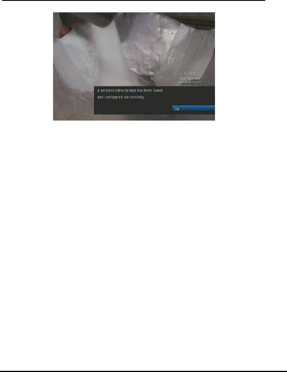
5) On the Genie server verify OSD “A wireless video bridge has been found
and configured successfully”. Select OK to clear the OSD. This often takes
only 30 seconds however it can take up to several minutes.
User Manual –Wireless Video Bridge Gen 2
Version 1.0.0 12/16/2016 Page 20
FIGURE 7: GENIE-WVB FOUND OSD
6) If the OSD does not display on the Genie server, check the WVB2 LED
and refer to the troubleshooting section.
7) Verify all WVB2s are connected to the Genie server by checking the WVB
status under Whole Home > Video Bridge > Video Bridge Status on the
Genie server.
• Each WVB in the system should show ACTIVE.
8) Installation of the WVB2 is complete once all WVB2s appear ACTIVE on
the Genie server’s Video Bridge Status screen and all WVB2s have a solid
GREEN or solid BLUE LED. (This means that the Genie server and the
WVB2 are connected, even though you may not have a wired or wireless
client connected).
E. A
DDING
W
IRELESS
C
LIENTS
(C61W)
Once the WVB2 is properly configured by the Genie server, the wireless client(s) (C61W)
can be added. The WVB2’s network status light should be Solid GREEN or BLUE (if
previous clients were connected)
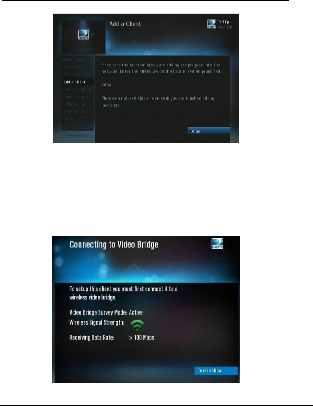
1) On the Genie server, go to “Add a Client” from the “Whole Home” menu and note
the PIN displayed on the screen. (These steps will change in Goliath and when in
Lenient mode or Full Client Tracking mode. See FE-TC D-088 Goliath/Flower
Tech Comm) Keep the Genie server on this screen until all wireless clients
(C61Ws) are installed and are at live video.
User Manual –Wireless Video Bridge Gen 2
Version 1.0.0 12/16/2016 Page 21
FIGURE 8: GENIE "ADD A CLIENT" SCREEN
2) Approximately ~30 seconds after entering the “Add a Client” screen at the
Genie Server, the WVB will have a flashing LED that alternates between
GREEN and BLUE. This indicates that the system is in the proper state to
add a wireless client (C61W).
3) If not already powered on, power ON one of the wireless clients (C41W,
C61Ws)
4) On the wireless client (C41W, C61W), select the “Connect Now”/”Continue”
button while in the “Connecting to Video Bridge” screen to begin client
connection and registration.
FIGURE 9: C41W "CONNECTING TO VIDEO BRIDGE" SCREEN
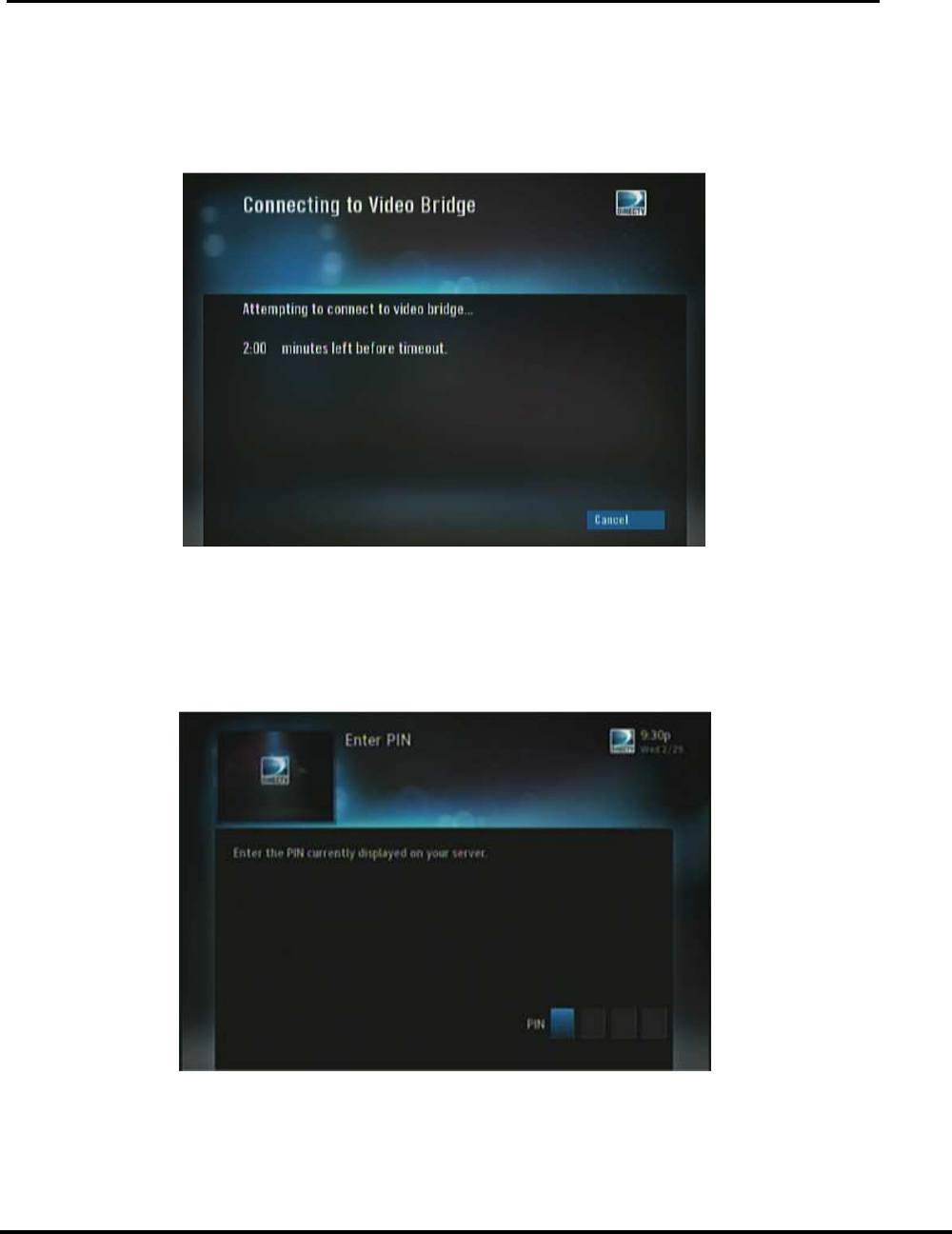
5) “Attempting to connect to video bridge…” will be displayed.
User Manual –Wireless Video Bridge Gen 2
Version 1.0.0 12/16/2016 Page 22
• The network led may flash RED while you are on this screen
• After this screen, it is common to see a momentary (3-5 seconds) gray
screen before the Enter PIN screen appears.
• If “Unable to connect to Video Bridge” OSD appears, see Troubleshooting.
FIGURE 10: C41W "ATTEMPTING TO CONNECT TO VIDEO BRIDGE" SCREEN
6) When wireless connection between the WVB2 and wireless client (C41W,
C61W) completes, enter the PIN provide by the Genie server. (This
process will change in Goliath and when in Lenient mode or Full Client
Tracking mode. The PIN will no longer be required. See FE-TC D-088
Goliath/Flower Tech Comm for all related changes)
FIGURE 11: C41W "ENTER PIN" SCREEN
• At any time throughout the installation, the Software Download OSD may
appear. If the OSD appears, then select “OK, Download” to start the
download. Do NOT exit Add Client on the Genie server until the download
completes.

Version 1.0.0 12/16/2016
•
If the Software Download fails,
wireless client (
•
Live TV: Do Nothing. If the download OSD appears, select “OK
Download”.
•
Enter PIN screen: If the download OSD appears, select “OK
Download”.
(even if you may have previously entered the PIN).
•
Select a Server OSD: Verify the Gene server is in the Add Client
screen, and ensure that the WVB LED is alternating Blue/Green.
7)
Once the PIN is entered
Client.
8)
If the user does not have enough Client services on the account, the user
will get a
DIRECTV to add the Client to their account.
9)
If the user has
the client service), the user will be taken to the “Name the Client”.
10)
User names the Client, and will have the option to copy/don’t copy the
location settings from a Genie server or another Client.
•
The wireless client (
flashing RED network LED, and/or may display the Wireless Connection Lost
OSD.
•
The OSD will clear, and the network LED will go back to Green after
10
–
•
If gray screen persists a
the channel to restore video.
•
If the above symptoms occur, the rest of the setup will be skipped,
and the installer should program the remote.
11)
Complete the wireless client (C6
and
selecting “Watch DIRECTV”
12)
If a 2nd and/or 3rd
of Add a Wireless Client. If
C61Ws)
,
adding
the addit
the same time.
13) After all
wireless clients (
and select
Do NOT exit the Add Client screen on the Genie server
(C6
1W) is downloading software.
User Manual –
Wireless Video Bridge Gen 2
Page 23
If the Software Download fails,
it will reboot itself. Once the clien
wireless client (
C41W, C6
1W) will be in one of three states ,
Live TV: Do Nothing. If the download OSD appears, select “OK
Download”.
Enter PIN screen: If the download OSD appears, select “OK
Download”.
If the download OSD does not appear, enter the PIN
(even if you may have previously entered the PIN).
Select a Server OSD: Verify the Gene server is in the Add Client
screen, and ensure that the WVB LED is alternating Blue/Green.
Once the PIN is entered
, the user selects “Adds a New Location” on the
If the user does not have enough Client services on the account, the user
will get a
‘Call DIRECTV’ screen on the Client. The user must call
DIRECTV to add the Client to their account.
If the user has
enough Client services (or once they call
the client service), the user will be taken to the “Name the Client”.
User names the Client, and will have the option to copy/don’t copy the
location settings from a Genie server or another Client.
The wireless client (
C41W, C6
1W) may go to gray screen, may have a
flashing RED network LED, and/or may display the Wireless Connection Lost
The OSD will clear, and the network LED will go back to Green after
–
20 seconds.
If gray screen persists a
nd the network LED is Green, then change
the channel to restore video.
If the above symptoms occur, the rest of the setup will be skipped,
and the installer should program the remote.
Complete the wireless client (C6
1W) setup by programming the remote
selecting “Watch DIRECTV”
If a 2nd and/or 3rd
wireless client (C6
1W) are needed, start from S
of Add a Wireless Client. If
more than 3
clients are to be added (4
,
place the other wireless client(s) (C61W)
in standby before
the addit
ional clients.
No more than 3 clients can be powered on at
the same time.
wireless clients (
C61W) have been added
, go
and select
DONE on the “Add a Client” screen.
Do NOT exit the Add Client screen on the Genie server
while the wireless client
1W) is downloading software.
Wireless Video Bridge Gen 2
it will reboot itself. Once the clien
t boots, the
1W) will be in one of three states ,
Live TV: Do Nothing. If the download OSD appears, select “OK
Enter PIN screen: If the download OSD appears, select “OK
If the download OSD does not appear, enter the PIN
(even if you may have previously entered the PIN).
Select a Server OSD: Verify the Gene server is in the Add Client
screen, and ensure that the WVB LED is alternating Blue/Green.
, the user selects “Adds a New Location” on the
If the user does not have enough Client services on the account, the user
‘Call DIRECTV’ screen on the Client. The user must call
enough Client services (or once they call
DIRECTV to add
the client service), the user will be taken to the “Name the Client”.
User names the Client, and will have the option to copy/don’t copy the
location settings from a Genie server or another Client.
1W) may go to gray screen, may have a
flashing RED network LED, and/or may display the Wireless Connection Lost
The OSD will clear, and the network LED will go back to Green after
nd the network LED is Green, then change
If the above symptoms occur, the rest of the setup will be skipped,
1W) setup by programming the remote
1W) are needed, start from S
tep (3)
clients are to be added (4
-8
in standby before
No more than 3 clients can be powered on at
, go
to the Genie server
while the wireless client

Version 1.0.0 12/16/2016
After selecting Done,
may have a flashing RED network LED, and/or may have the Wireless
Connection Lost OSD. The OSD should disappear and the
to Green.
If gray screen persists, then wait 2 minutes before troubleshooting.
14) All
wireless clients (
LEDs.
After
F. F
INAL
C
HECKS
1) Turn
on the Genie server and up to 3 clients.
2)
Run System Test on the Genie server and ensure there are no Error
Codes.
3)
Confirm that the LED on the WVB
4)
Ensure the network LED on Clients 1, 2 and 3 (wired and wireless) is
GREEN and confirm Live TV
button. The client will display “Internet connected”).
5)
If the customer has more than 3 clients, put Clients 1, 2 and 3 into Standby,
and turn on clients 4, 5 and 6.
6)
Reconfirm that the LED on the WVB
7)
Ensure the network LED on the Client 4, 5 and 6 is GREEN and confirm
LiveTV.
8)
If the customer as a 7
and turn on Clients 7 and 8.
9)
Reconfirm that the LED on the WVB
10)
Ensure the network LED on clients 7 and 8 is GREEN and confirm LiveTV.
T
he following diagram shows the connection between the Genie, WVB
User Manual –
Wireless Video Bridge Gen 2
Page 24
After selecting Done,
the wireless client (C6
1W) may go to gray screen,
may have a flashing RED network LED, and/or may have the Wireless
Connection Lost OSD. The OSD should disappear and the
If gray screen persists, then wait 2 minutes before troubleshooting.
wireless clients (
C61W) that are ON should have
solid GREEN network
After
1-2 minutes the WVB2
LED should display a solid BLUE.
on the Genie server and up to 3 clients.
Run System Test on the Genie server and ensure there are no Error
Confirm that the LED on the WVB
2 is Solid Blue.
Ensure the network LED on Clients 1, 2 and 3 (wired and wireless) is
GREEN and confirm Live TV
(If internet connected, press the “Dash” (
button. The client will display “Internet connected”).
If the customer has more than 3 clients, put Clients 1, 2 and 3 into Standby,
and turn on clients 4, 5 and 6.
Reconfirm that the LED on the WVB
2 should sti
ll be Solid Blue.
Ensure the network LED on the Client 4, 5 and 6 is GREEN and confirm
If the customer as a 7
th
and 8
th
client, put the other Clients into Standby
and turn on Clients 7 and 8.
Reconfirm that the LED on the WVB
2
should still be Soli
Ensure the network LED on clients 7 and 8 is GREEN and confirm LiveTV.
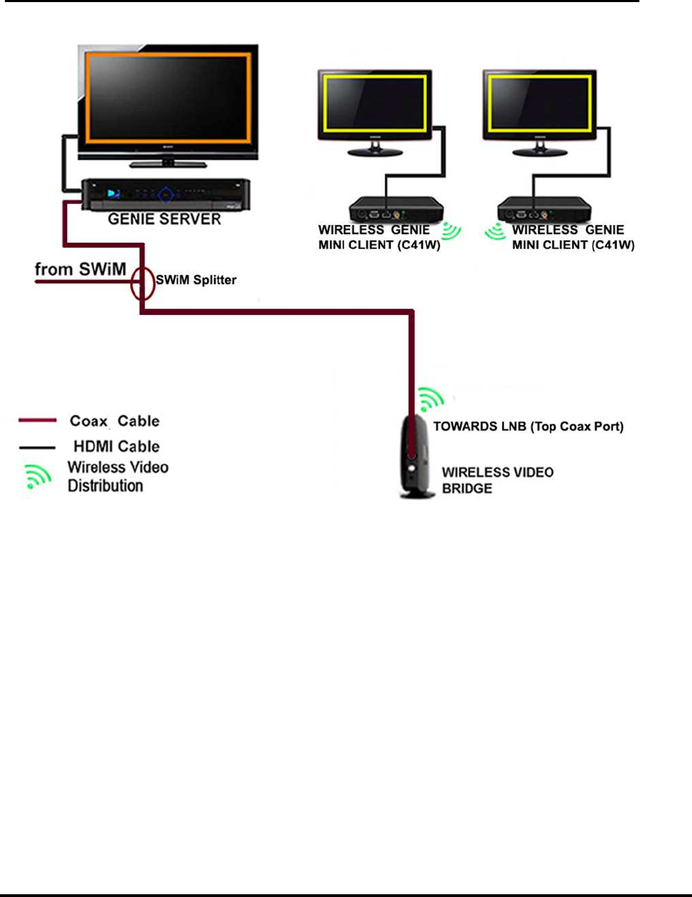
he following diagram shows the connection between the Genie, WVB
Wireless Video Bridge Gen 2
1W) may go to gray screen,
may have a flashing RED network LED, and/or may have the Wireless
Connection Lost OSD. The OSD should disappear and the
LED will go back
If gray screen persists, then wait 2 minutes before troubleshooting.
solid GREEN network
LED should display a solid BLUE.
Run System Test on the Genie server and ensure there are no Error
Ensure the network LED on Clients 1, 2 and 3 (wired and wireless) is
(If internet connected, press the “Dash” (
-)
If the customer has more than 3 clients, put Clients 1, 2 and 3 into Standby,
ll be Solid Blue.
Ensure the network LED on the Client 4, 5 and 6 is GREEN and confirm
client, put the other Clients into Standby
should still be Soli
d Blue.
Ensure the network LED on clients 7 and 8 is GREEN and confirm LiveTV.
he following diagram shows the connection between the Genie, WVB
2 and C61W.
User Manual –Wireless Video Bridge Gen 2
Version 1.0.0 12/16/2016 Page 25
FIGURE 12: WVB AND C41W INSTALLATION DIAGRAM
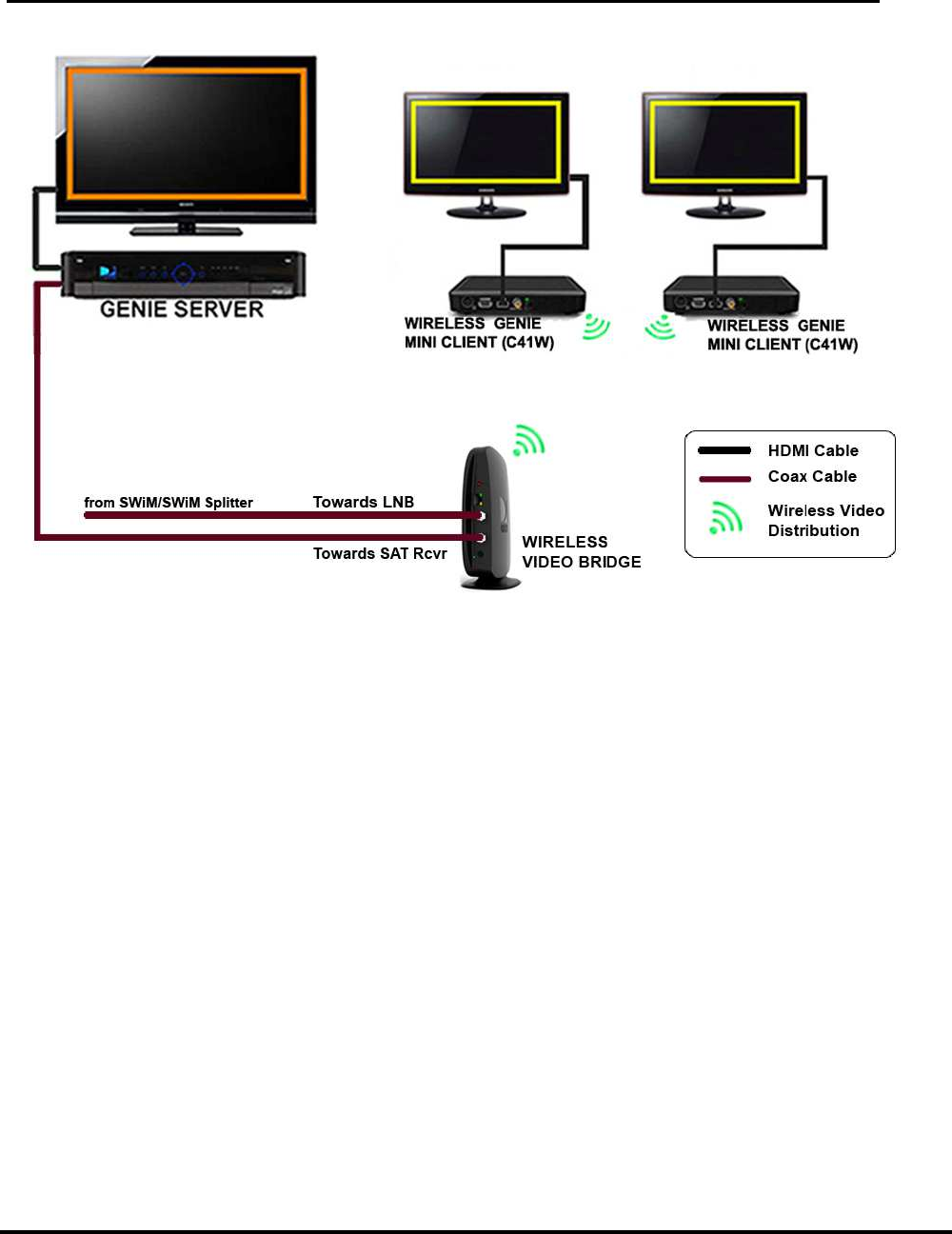
The diagram on the following page depicts an alternate approved installation for a Genie, WVB2
and C61W setup:
User Manual –Wireless Video Bridge Gen 2
Version 1.0.0 12/16/2016 Page 26
FIGURE 13: WVB AND C41W INSTALLATION DIAGRAM (ALTERNATE INSTALLATION)
G. R
EMOVE
WVB2
FROM THE
G
ENIE
S
ERVER
This process is only intended to be used if the WVB2 is to be permanently removed from the
Genie server. If replacing a WVB2, go to the “Replace WVB” section in this document. If
more than one WVB2 has been installed and a WVB is removed permanently, this
procedure should be performed to stop an error from occurring on the Genie server. (These
steps will change in Goliath and when in Lenient mode or Full Client Tracking mode. see
FE-TC D-088 Goliath/Flower Tech Comm)
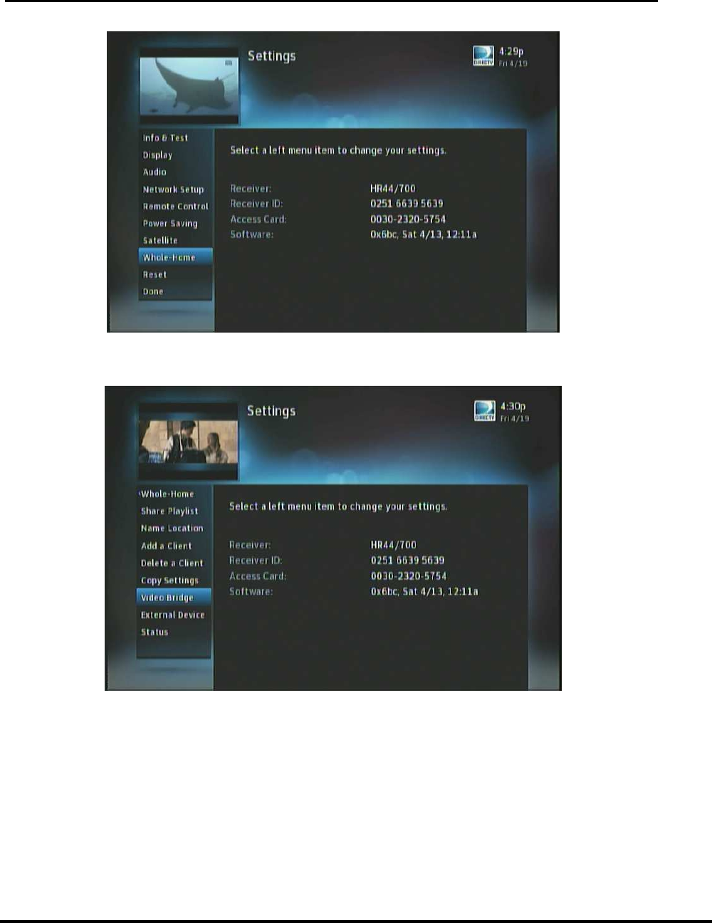
1) Navigate to Menu -> Settings & Help -> Settings.
User Manual –Wireless Video Bridge Gen 2
Version 1.0.0 12/16/2016 Page 27
FIGURE 14: GENIE SETTINGS SCREEN
2) Select Whole-Home -> Video Bridge.
FIGURE 15: GENIE SELECT VIDEO BRIDGE SCREEN
3) If a WVB2 is configured to the network, the “Remove Video Bridges” option
is enabled.
User Manual –Wireless Video Bridge Gen 2
Version 1.0.0 12/16/2016 Page 28
FIGURE 16: GENIE REMOVE VIDEO BRIDGES SCREEN
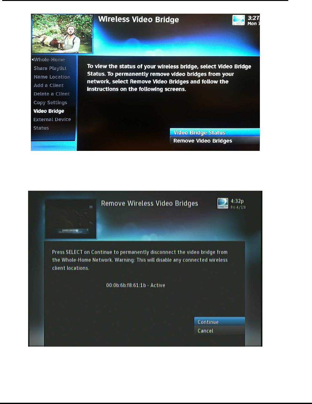
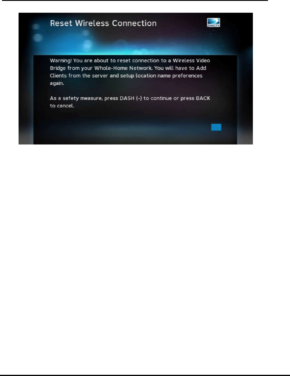
4) Select the option Remove Video Bridges. The screen will list all the
WVB2’s that are configured to the network. Select “Continue” to remove
the WVB2.
FIGURE 17: GENIE REMOVE WIRELESS VIDEO BRIDGES SCREEN 1
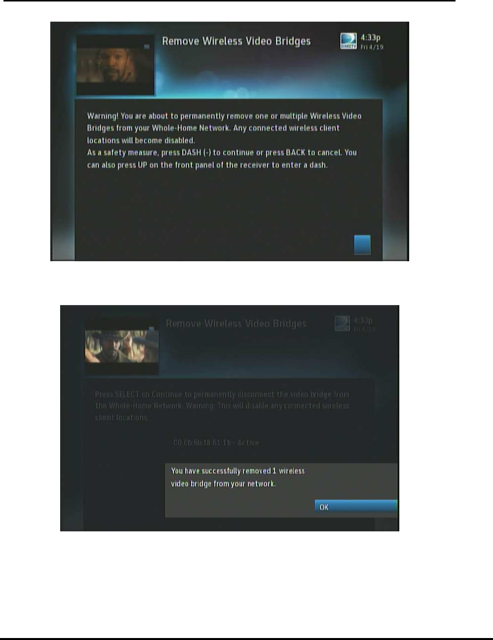
5) Follow the on-screen instructions and press “-“to complete the removal of
the WVB2.
User Manual –Wireless Video Bridge Gen 2
Version 1.0.0 12/16/2016 Page 29
FIGURE 18: GENIE REMOVE WIRELESS VIDEO BRIDGES SCREEN2
6) A successful completion OSD will appear. Press “OK”.
FIGURE 19: GENIE - WVB REMOVAL CONFIRMATION SCREEN
7) The removal will cause the wireless clients (C61Ws) that are paired with
this WVB2 to disconnect from the wireless network.

User Manual –Wireless Video Bridge Gen 2
Version 1.0.0 12/16/2016 Page 30
VI. T
ROUBLESHOOTING FOR
OSD
AND
D
IAGNOSTICS
H. C
LIENT
S
YMPTOMS AND
T
ROUBLESHOOTING
4. Wireless Client (C61W) Grey/Black screen no Banner
Technician Troubleshooting:
8) If the wireless client (C61W) network LED is Green, then follow normal
Gray/Black screen troubleshooting.
• Change channels
• Turn off the wireless client (C61W) for 15 seconds and then turn it back on.
• Verify the customer’s TV is on the correct input
• Verify cables and connection to the TV is good (including trying a different
cable and input to the TV)
If the LED is not Green, or normal Gray/Black troubleshooting does not resolve
then continue to step 2.
9) Run system test on the Genie server. Troubleshoot any error codes that appear
(see Genie error code table).
a. If there are no error codes, check the LED status light on WVB2.
b. If LED is not BLUE then see WVB2 LED status troubleshooting
c. If WVB2 LED is BLUE, then check LED status light on the wireless
client (C61W)
d. If LED is not Solid GREEN then see wireless client (C61W) LED status
troubleshooting
e. Extra steps for Technicians ONLY (The “Excellent”/”Good” text that is
referenced below is already in the Genie servers screens, however
they should not be used until the Genie Server has the Goliath
Software)
10) On the Genie Server go to Setting & Help >/ Settings > Info & Test > More
System Info
11) Scroll down to the Wireless Client(s) that is having the issue and look at its
“RSSI”.
12) If the RSSI does not show “Excellent” then troubleshoot the same as a “Yellow”
Network LED on the C61W”
Note: “Good” status is normally acceptable unless the customer is complaining of
intermittent issues. “Good” indicates that the Network LED is Green, but it might
be on the edge of going to “Yellow”. RSSI value of “Excellent” helps to ensure that
there are enough margins to overcome interferences in the customer’s home.
a. If internet connected, power-cycle the router.
b. Reset the WVB2
c. Reset the Genie server, and wait for it to boot up to video

User Manual –Wireless Video Bridge Gen 2
Version 1.0.0 12/16/2016 Page 31
d. If the client does not have LiveTV, reset the client, wait for client
network LED to turn Green and wait 2 minutes.
e. If not resolved, agents setup a service call
f. If not resolved, Technicians:
If the server is connected to the router wirelessly (HR44 internal Wi-Fi/CCK-W)
then change to a BB-DECA, and refer to “Resetting a Genie with Clients” section
above. If still unresolved, escalate to FPR.
Agent Troubleshooting:
1) Verify the TV is on.
2) On the C61W, verify the front power button lights up solid blue.
a. If blinking Blue, there is a software download in progress. Wait 5
minutes
b. If no blue light, troubleshoot for Receiver Will Not Turn On.
3) Channel up or down
4) If video does not return, then turn the C61W Off, then On
5) If video does not appear, then Press Guide on the remote.
a. If the Guide appears, then Continue to Step 6
b. If the Guide does not appear, then follow the below to check
connections and Input
• Press the Input button on the DIRECTV remote.
1. Ask the customer to slowly cycle through the TV's video inputs.
2. If one input setting gives a clear picture with the Guide, advise
the customer to set the TV to that input for DIRECTV service.
• If using HDMI:
1. Turn the TV off and on to reinitialize the HDMI port.
a) If successful, escalate to NET -- noting the customer's TV
model.
2. Verify the HDMI cable is connected to the HDMI jack on receiver
and TV.
3. Disconnect and reconnect the cable from the receiver to the TV;
make sure the connections are secure.
a) This re-establishes the 2 way communication between the
receiver and the customer's TV.
b) If successful, escalate to NET -- noting the customer's TV
model.
4. Try an alternate HDMI jack.
a) Some TVs have more than one HDMI input; make sure to
change the TV input to match the alternate HDMI jack.
5. If there's an A/V receiver or any other device attached, remove it;
run the HDMI cable directly from the receiver to the TV.
6. Try using component cables (i.e., 10-pin Connector) with audio
cables and change the TV input to Component -- Offer Cords &
Cables if needed.

User Manual –Wireless Video Bridge Gen 2
Version 1.0.0 12/16/2016 Page 32
6) Run a system test on the Genie server.
7) If no diagnostic code, check the color of the Network LED on the C61W.
a. Not solid green: Troubleshoot per the LED color.
b. Solid Green: Continue.
8) Check the color of the Network LED on the Wireless Video Bridge.
a. Not solid blue: Troubleshoot per the LED color.
b. Solid Blue: Continue.
9) If issue persists, reboot the C61W.
a. When rebooting C61W, pay attention to any screens that appear during
the bootup. If the initial screen appears (Hello, Your DIRECTV receiver
is starting up), but Live TV does not appear then you may need further
troubleshooting after rebooting the Genie Server
10) If issue persists, reboot the Genie Server
11) If issue persists, and during the C61W boot up, did the customer see the “Hello,
Your DIRECTV receiver is starting up” screen?
a. If Yes, then reset the C61W to Factory Default setting
1. On the C61W pressing and holding the DIRECTV Logo Power
button for 5-10 seconds (This is the Power button, NOT the Red
Reset button)
2. When the power button is released, the receiver will reboot up to
factory defaults.
3. Does the customer now see video
a) If no, then Offer a Service Call
b) If yes, then C61W was probably in a resolution that their TV
does not support. Since the customer has reverted their C61W
to factory default, you now need to help , the customer with
some of their settings
i. Remote
• If the customer is not using the RC71 or higher remote,
then you can skip this step. If they have an RC71, reset the
remote to IR mode, then reprogram the RF mode
I. On the remote, press and hold MUTE and Select.
II. Green LED blinks twice.
III. Press 9-8-7
IV. Green LED blinks Red for less than a second times
<<yes RED is correct, the remote spec says green flash
4x but that is not how the remote works>>
V. The remote should now control the C61W and the TV
setting should remain
VI. If the customer wished to be in RF mode, then follow
Enable RF for the Genie Remote
ii. If needed, help the customer with setting up Favorites,
Parental Controls, Resolution and TV

User Manual –Wireless Video Bridge Gen 2
Version 1.0.0 12/16/2016 Page 33
b. If Nothing was seen during the C61W boot up, then Offer a Service
Call.
5. C61W Program Banner displayed, no Video on TV
Troubleshooting: Refer to Troubleshooting steps above.
6. C61W Video/Audio on TV but no Menu, Guide or List displays
Troubleshooting: Refer to troubleshooting steps above.
7. Freeze Frame/Pixelization on wireless client (C61W)
Troubleshooting: Refer to Troubleshooting steps above.
8. C61W does not display the Enter PIN screen
Troubleshooting:
13) If the Genie server is not in “Add a Client” screen, put the Genie server in the
Add Client mode and follow the installation procedures.
14) If that does not resolve the issue,
• Agents set up a service call.
• Technicians – Follow installation steps.
9. Wireless client (C61W): Add a Client failed (does not display video after Add a
Client exited)
Troubleshooting: Refer to Troubleshooting steps above (Gray/Black screen
troubleshooting).
10. Wireless Client (C61W) Network LED Failures (Bad Wireless Connection)
Symptom
• WVB2 has a Solid Red LED
• And/or Wireless Client has Yellow, Red or Blinking Red Network LED
Probable Cause
• Poor placement of the WVB2 and/or Wireless Client
Installer Training Troubleshooting
1) For Yellow or Solid Red Network LED on the Wireless Client:
a) Ensure there are no obstacles around the WVB2 or the Wireless Client that
would degrade signal quality.
b) Try moving the WVB2 to a better location to improve the signal to the
Wireless Client locations. Remember the minimum distance guidelines to
separate the WVB2 from other wireless devices like the customer’s router, an
HR44 with built-in WiFi, or, for example, a Playstation with a WiFi connection.
2) For a blinking Red network LED on the Wireless Client:
a) Put the Genie Server back into “Add Client” mode (Menu > Settings &
Help > Settings > Whole Home > Manage Clients > Add Client)
User Manual –Wireless Video Bridge Gen 2
Version 1.0.0 12/16/2016 Page 34
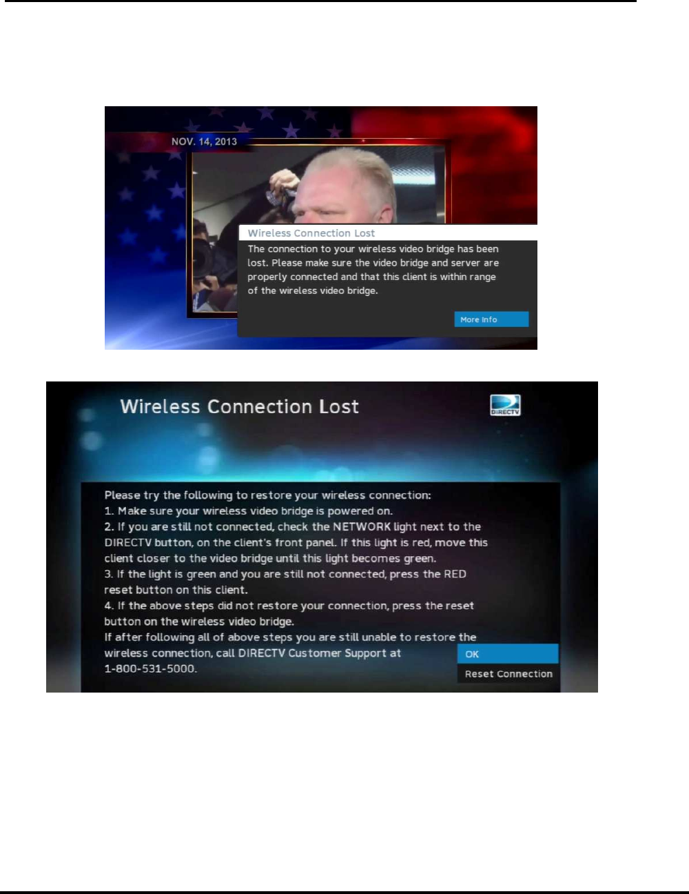
b) If the Wireless Connection was lost while watching video, the “Wireless
Connection Lost” screen will appear. (if the Wireless Client was in Standby,
“Select a Server/ No Server Detected” will appear and will change to the
Wireless Connection Lost OSD)
c) Select “More Info, then “Reset Connection” from the C61W on-screen display
User Manual –Wireless Video Bridge Gen 2
Version 1.0.0 12/16/2016 Page 35
d) The follow the installation steps to check the signal strength and pair the
Wireless Client
I. OSD
T
ROUBLESHOOTING
11. Genie server OSD:
“Wireless Connection Lost. The connection to wireless video bridge has been lost.
Please make sure all wireless video bridges are connected and have power. If the
problem persists call DIRECTV at 1-800-531-5000”
Probable Cause:
• The WVB2 lost connection to the Genie server
• The WVB2 lost power or is rebooting
• Troubleshooting should focus on the connection from the WVB2 to the
Genie server
Troubleshooting
15) Check if the clients are having a problem. If yes, troubleshoot client symptoms.
16) If no, educate customer that the OSD was temporary and choose to ignore OSD.
12. Wireless Client (C61W) OSD:
“Wireless Connection Lost. The connection to wireless video bridge has been lost.
Please make sure all wireless video bridges and server are properly connected and that
this client is within range of the wireless video bridge”
Probable Cause:
• The WVB2 lost connection to the Genie server
• The WVB2 lost power or is rebooting
Version 1.0.0 12/16/2016
• The
wireless client (
Troubleshooting
17)
Check the C61W LED and troubleshoot accordingly.
18)
If LED is GREEN, troubleshoot as per C61W Grey/Black screen symptoms.
13. Wireless Client (
C61W
“Select a S
erver. No Servers Were detected. Check your network connections”
Technician
Troubleshooting:
19)
Verify the wireless client (C61W) network LED is Green
•
If the LED is Green, allow 2 minutes for the Live TV to return
20)
If the wireless client (C61W) network LED is
needed in case the WVB2 has not loaded the new software)
21)
Treat the same as Genie Server OSD “Wireless Connection Lost”
Agent Troubleshooting
Troubleshooting should focus on the connection from the Wireless Video
to the Genie server.
22)
Run system test on the Genie server
23)
If no diagnostic code,
•
If light is not solid blue, troubleshoot as per the LED color.
•
If light is solid blue, continue.
24)
Ensure the Coax
attached " and finger tight.
25)
Reset the Wireless Video Bridge.
26)
Reset the Genie server.
27)
If issue persists, schedule a service call.
14. Wireless Client (
C61W
“
Connecting to Video Bridge
Prob
able Cause and Troubleshooting:
28)
Make sure the Genie server is in the Add
29) Follow
the normal installation process starting at Connect Now on the
wireless client (C61W).
15. Wireless Client (
C61W
“
Unable to connect to Video Bridge. Make su
and this client is within range of your video bridge signal”
User Manual –
Wireless Video Bridge Gen 2
Page 36
wireless client (
C61W) is not in range of the WVB2
Check the C61W LED and troubleshoot accordingly.
If LED is GREEN, troubleshoot as per C61W Grey/Black screen symptoms.
C61W
) OSD:
erver. No Servers Were detected. Check your network connections”
Troubleshooting:
Verify the wireless client (C61W) network LED is Green
If the LED is Green, allow 2 minutes for the Live TV to return
If the wireless client (C61W) network LED is
blinking Red, reset the WVB2 (this is
needed in case the WVB2 has not loaded the new software)
Treat the same as Genie Server OSD “Wireless Connection Lost”
Agent Troubleshooting
Troubleshooting should focus on the connection from the Wireless Video
to the Genie server.
.
Run system test on the Genie server
If no diagnostic code,
ensure Wireless Video Bridge lights is solid BLUE.
If light is not solid blue, troubleshoot as per the LED color.
If light is solid blue, continue.
Ensure the Coax
cables on the Wireless Video Bridge and Server is properly
attached " and finger tight.
Reset the Wireless Video Bridge.
Reset the Genie server.
If issue persists, schedule a service call.
C61W
) OSD:
Connecting to Video Bridge
”
able Cause and Troubleshooting:
Make sure the Genie server is in the Add
a Client Screen.
the normal installation process starting at Connect Now on the
wireless client (C61W).
C61W
) OSD:
Unable to connect to Video Bridge. Make su
re that the video bridge is in survey mode
and this client is within range of your video bridge signal”
Wireless Video Bridge Gen 2
C61W) is not in range of the WVB2
If LED is GREEN, troubleshoot as per C61W Grey/Black screen symptoms.
erver. No Servers Were detected. Check your network connections”
If the LED is Green, allow 2 minutes for the Live TV to return
blinking Red, reset the WVB2 (this is
needed in case the WVB2 has not loaded the new software)
Treat the same as Genie Server OSD “Wireless Connection Lost”
Troubleshooting should focus on the connection from the Wireless Video
Bridge
ensure Wireless Video Bridge lights is solid BLUE.
If light is not solid blue, troubleshoot as per the LED color.
cables on the Wireless Video Bridge and Server is properly
the normal installation process starting at Connect Now on the
re that the video bridge is in survey mode

User Manual –Wireless Video Bridge Gen 2
Version 1.0.0 12/16/2016 Page 37
Probable Cause and Troubleshooting:
30) Select the OK button will bring the user back to connect to video bridge screen
31) Ensure the Genie server is on the Add Client Screen,
32) Ensure that the WVB2 LED is alternating Blue/Green.
33) Make sure you are not selecting “Connect now” or “Continue” on more than
one client at a time.
J. G
ENIE
S
ERVER
E
RROR
C
ODE
T
ABLE
The Genie server has additional error codes for troubleshooting the WVB2 and wireless
clients (C61W). These are listed in the table below. These codes may be displayed after
running system test on the Genie server.
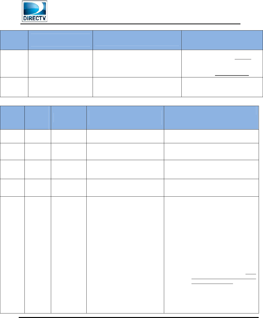
Diagnostic
Code Text Cause
Troubleshooting
Steps for Tech
Training
Troubleshooting Steps for
Agents
89 (Genie
only) “Unable to connect to the
Wireless Video Bridge(s) on
your network. In order to
display any video the
receiver needs to be
connected to a Wireless
Video Bridge. Please verify
that all Wireless Video
Bridges on your network are
powered on and have the
coaxial cable connected.
Select \"Test Again\" to see
if this has solved the issue.”
Diagnostic Code: 89
The Genie server
does not detect
the WVB2
1) Determine if the WVB2
was deliberately
removed from the
network by the
customer. If it was,
walk customer through
removing the WVB2
from the Genie by using
the system menus.
2) Ensure all WVB2s are
powered on.
3) .
1) Ensure the Wireless Video
Bridge is powered ON by
checking if the DC jack power
LED is lit up GREEN.
2) Is the LED light on the
Wireless Video Bridge blinking
RED?
• YES: Reset the Wireless
Video Bridge.
° If Wireless Video
Bridge's LED light
continues to blink Red,
“Replace WVB2”.
• NO: Continue.
3) Ensure that the coax cables to
the Wireless Video Bridge and
Server are properly connected
" and finger tight.
4) Delete all WVB2s from Genie
Server by going to Menu >
Settings & Help > Settings >
Whole-Home > Remove Video
Bridge (Add Why Component:
WVB2s will be reacquired by
the Genie Server after the
below resets are completed)
5) eset the Wireless Video
Bridge.
6) Reset the Genie server.
If issue persists, schedule a service
call.

User Manual –Wireless Video Bridge Gen 2
Version 1.0.0 12/16/2016 Page 38
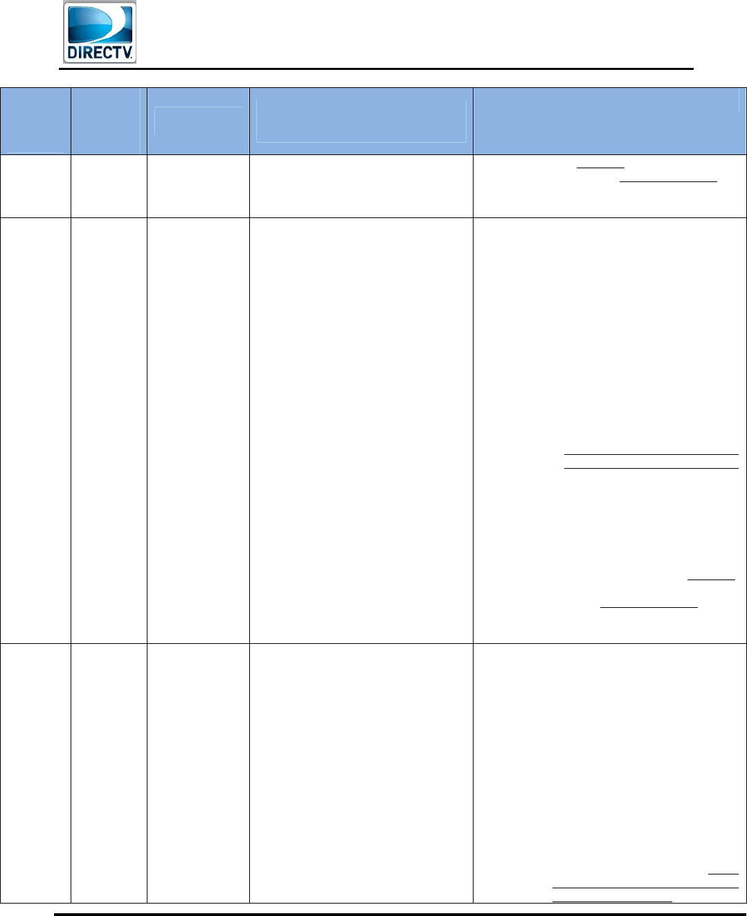
Diagnostic
Code Text Cause
Troubleshooting
Steps for Tech
Training
Troubleshooting Steps for
Agents
90 (Genie
only) “One or more of the
Wireless Video Bridges on
your network reports an
error. You may experience
poor quality or intermittent
loss of video on your
wireless clients. Please
reset your Wireless Video
Bridge(s) using the red reset
button on the back panel.
Select \"Test Again\" to see
if this has solved the issue.”
Diagnostic Code: 90
WVB2 Internal
Error. (Hardware
Issue)
1) Perform a reset on
the WVB2.
2) If WVB2 continues
to blink Red, replace
the WVB2.
3)
Note: If the customer has more
than one Wireless Video Bridge,
advise customer to find the one that
DOES NOT have a solid blue light.
1. Reset the Wireless Video
Bridge.
2. If issue persists, Replace
the WVB2 that has a
blinking Red LED.
91 (Genie
only) “One or more of the
Wireless Video Bridges on
your network reports an
error. You may experience
poor quality or intermittent
loss of video on your
wireless clients. Please
check the coaxial cable
connection to your Wireless
Video Bridge(s) then reset
them using the red reset
button on the back panel.
Select \"Test Again\" to see
if this has solved the issue.”
Diagnostic Code: 91
WVB2 MoCA
Error.
Troubleshoot the MoCA /
Coax network. Verify cabling
and connectors.
• If the customer has more than
one Wireless Video Bridge,
advise customer to find the
one that DOES NOT have a
solid blue light.
• Although issues may be seen
on the C61W, the issue is not
with the communication
between the Wireless Video
Bridge and C61W.
1) Ensure that the coax cables to
the Wireless Video Bridge and
Genie Server are properly
connected and finger tight.
2) If issue persists, schedule a
service call
92 (Genie
only) “One or more of the
Wireless Video Bridges on
your network reports an
error. You may experience
poor quality or intermittent
loss of video on your
wireless clients. Please
reset your Wireless Video
Bridge(s) using the red reset
button on the back panel.
Select \"Test Again\" to see
if this has solved the issue.”
Diagnostic Code: 92
WVB2 Ethernet
Error. Should not occur. Escalate to
NET, NET to escalate to STB
Field Support..
Should not occur.
Escalate to NET, NET to escalate
to STB Field Support.

Field Engineering – Technical Communications –Wireless Video Bridge Gen 2
Version 1.0.0 12/16/2016 Page 39
DIRECTV, Inc. Proprietary and Confidential
VII. O
THER
T
ROUBLESHOOTING
K. WVB2
LED
T
ROUBLESHOOTING
LED
State Description Troubleshooting Steps Troubleshooting Steps for
Agents
Off Device not powered
1) Plug in the approved power supply to a
reliable power source.. 1) Check the Power LED on the
rear panel of the Wireless
Video Bridge. It should be
GREEN.
2) If not Green, plug in the Power
Supply, then if still not Green
then replace Power Supply
3) If green, replace WVB2
Solid Blue
Normal Operation
Wireless clients (C61W) should
have a connection to the Genie
server.
No Action.
No Action
Blink Blue Booting up.
Start within 10 seconds of
power ON.
1) Normal WVB2 boot up process, takes
approximately 2 minutes.
1) Wait for Boot up.
2) Normal Wireless Video Bridge
boot up process, takes
approximately 2 minutes
3) It may take an additional 3-5
minutes for the C61W to get
video
Solid Green
Good Connection to the Genie
server but No Clients paired
with WVB2.
1) Follow “Adding Wireless Clients” steps
to pair and register the Wireless Clients.
1) Wireless Clients need to be
powered ON so that the
Registration process can start.
2) Complete the steps to add a
wireless client.
Blinking
Green
Bridge in Survey/Beacon Mode
MoCA network connected
No communication from Genie
server to the WVB2
This is normal when initially connecting
to the MoCA network. Allow 5 minutes
for the LED to change to Solid Green.
This is normal when initially connecting
to the SWiM / MoCA network. Allow 5
minutes for the LED to change to Solid
Green.
Blink Green
and Yellow
Wireless Video Bridge Survey
/Beacon Mode.
No MoCA Network Established
1) Normal Wireless Video Bridge
survey/Beacon mode without MoCA
network connected.
2) Used to position the WVB2 and Clients
during the Wireless Video Bridge
survey/Beacon Mode.
3)
1) Normal Wireless Video Bridge
Survey mode without a coax
network connected.
2) Used to position the Wireless
Video Bridge and Clients during
the installation.
3) Offer a service call.
Blink Green
and Blue Wireless Client Add mode 1) Normal state when adding wireless
clients (C61W).
2) See Adding Wireless Client for next
1) Normal state when adding
wireless clients.
2) Should turn solid BLUE

Field Engineering – Technical Communications –Wireless Video Bridge Gen 2
Version 1.0.0 12/16/2016 Page 40
DIRECTV, Inc. Proprietary and Confidential
LED
State Description Troubleshooting Steps Troubleshooting Steps for
Agents
steps once Genie server is out of this
mode.
3) Complete the steps to add a
wireless client
Solid Yellow
MoCA Network Established.
MoCA Phy Rate < 180 Mbps
(Note: Although issues will be
seen on the wireless client
(C61W), the issues is not with
the communication between the
WVB2 and C61W)
Troubleshoot the MoCA / Coax network.
Verify cabling and connectors.
1) Ensure the Coax cables on the
Wireless Video Bridge and
Genie Server are properly
attached and finger tight.
2) If issue persists, offer a service
call.
Blink Yellow
No MoCA Network Detected.
(Note: Although issues will be
seen on the wireless client
(C61W), the issues is not with
the communication between the
WVB2 and C61W)
Troubleshoot the MoCA / Coax network.
Verify cabling and connectors..
1. Ensure the Coax cables on the
Wireless Video Bridge and Genie
Server are properly attached and
finger tight.
2. Reset Wireless Video Bridge by
unplugging and plugging it back in
(same as pressing the reset button).
3. Reset the Genie server.
4. If issue persists, offer a service call.
Solid Red
The WVB2 has a good
connection to the Genie server;
however there is a Poor
Wireless connection to one or
more wireless clients (C61W).
Follow “Wireless Client (C61W) Network
LED Failures“ troubleshooting, above,
focusing on the Wireless Client(s) that
has a Yellow or Red Network LED
1. Ensure that the Wireless Video
Bridge is in a vertical position.
2. If possible, ensure that there are no
obstructions (e.g., cabinets or TV).
3. Did the customer move the Wireless
Video Bridge?
a) YES: Move the Wireless Video
Bridge back to its original
location.
b) NO: Continue.
4. Did the customer move any C61W
from its original location?
a) YES: Ensure all C61W is in a
location where its Network
Status LED is GREEN.
If customer cannot get a
GREEN LED, explain
that the range between
C61W and the Wireless
Video Bridge is limited
and either:
i. Have customer
move the C61W
back to the original
location, or
ii. If the customer does
not want to move
the C61W back to
Field Engineering – Technical Communications –Wireless Video Bridge Gen 2
Version 1.0.0 12/16/2016 Page 41
DIRECTV, Inc. Proprietary and Confidential
LED
State Description Troubleshooting Steps Troubleshooting Steps for
Agents
the original location,
offer a Relocate.
b) NO:
If issue persists, offer a service call.
Blink Red Device Error Detected 1) Perform a reset on the WVB2.
2) If WVB2 continues to blink Red, replace
the WVB2.
1. Perform a reset on the Wireless
Video Bridge.
2. If issue persists, Replace the WVB2
L. W
IRELESS
C
LIENT
C61W
T
ROUBLESHOOTING
Power
LED
State
Network
LED
State
Description
Troubleshooting Steps for
Tech Training
Troubleshooting Steps for Agents
OFF OFF Device not
powered
1) Plug in the approved power supply
to a reliable power source).
See normal troubleshooting for Receiver
Will Not Turn On
Flashing
Blue Any
Client is
updating
Software
Allow the C61W to finish
downloading. Update could complete
2-3 minutes
Allow the C61W to finish downloading. Update
may take 2-3 minutes
ON OFF Wireless client
(C61W) booting
Allow wireless client (C61W) to finish
booting. wireless client (C61W) should
boot in 1-2 minutes
Allow C61W to finish booting.
•
May take 1-2 minutes
ON GREEN Normal
operation
1) This means the customer had a
good connection to the WVB2.
.
No Troubleshooting needed on the
C61W.
ON YELLOW
wireless client
(C61W)
connected;
But poor
connection to
the WVB2. This
may adversely
affect
performance.
Focus should
be on WVB2
placement.
1) Follow “Wireless Client (C61W)
Network LED Failures”
troubleshooting above
1. Ensure that the Wireless Video Bridge is in
a vertical position.
2. If possible, ensure that there are no
obstructions (e.g., cabinets or TV ).
3. Did the customer move the Wireless Video
Bridge?
a) YES: Move the Wireelss Video Bridge
back to its original location.
b) NO: Continue.
4. Did the customer move the C61W from its
original location?
a) YES: Ensure the C61W is in a
location where its Network Status
LED is GREEN.
If customer cannot get a GREEN
LED, explain that the range
between C61W and the Wireless
Video Bridge is limited and either:
i. Have customer move the
C61W back to the original
location, or
ii. If the customer does not want
to move the C61W back to
the original location, offer a
Field Engineering – Technical Communications –Wireless Video Bridge Gen 2
Version 1.0.0 12/16/2016 Page 42
DIRECTV, Inc. Proprietary and Confidential
Power
LED
State
Network
LED
State
Description
Troubleshooting Steps for
Tech Training
Troubleshooting Steps for Agents
Relocate.
If issue persists, offer a service call.
ON RED
Wireless Client
(C61W)
Connected.
But poor signal
strength; This
may adversely
affect the
performance
1) Follow “Wireless Client (C61W)
Network LED Failures”
troubleshooting above
1) Ensure that the Wireless Video Bridge is
in a vertical position.
2) If possible, ensure that there are no
obstructions (e.g., cabinets or TV ).
3) Did the customer move the Wireless Video
Bridge?
a. YES: Move the Wireless Video Bridge
back to its original location.
b. NO: Continue.
4) Did the customer move the C61W from its
original location?
a. YES: Ensure the C61W is in a
location where its Network Status
LED is GREEN.
i. If customer cannot get a
GREEN LED, explain that the
range between C61W and the
Wireless Video Bridge is limited
and either:
1. Have customer move the
C61W back to the
original location, or
2. If the customer does not
want to move the C61W
back to the original
location, offer a Relocate.
b. NO:
5) If issue persists, offer a service call.
ON Blinking
RED
Wireless client
(C61W) not
connected to
the WVB2.
1) Follow “Wireless Client (C61W)
Network LED Failures”
troubleshooting above.
1) Ensure that the Wireless Video Bridge is
in a vertical position.
2) If possible, ensure that there are no
obstructions (e.g., cabinets or TV ).
3) Did the customer move the Wireless Video
Bridge?
a. YES: Move the Wireless Video Bridge
back to its original location.
b. NO: Continue.
4) Did the customer move the C61W from its
original location?
a. YES: Ensure the C61W is in a
location where its Network Status
LED is GREEN.
i. If customer cannot get a GREEN
LED, explain that the range
between C61W and the Wireless
Video Bridge is limited and either:
Field Engineering – Technical Communications –Wireless Video Bridge Gen 2
Version 1.0.0 12/16/2016 Page 43
DIRECTV, Inc. Proprietary and Confidential
Power
LED
State
Network
LED
State
Description
Troubleshooting Steps for
Tech Training
Troubleshooting Steps for Agents
1. Have customer move the
C61W back to the original
location, or
2. If the customer does not want
to move the C61W back to the
original location, offer a
Relocate.
b. NO: Continue
5) If the WVB2 was just reset, allow 3-5
minutes for the C61W connect and show
live video.(The C61W Network LED
should change to green)
6) If still flashing red.
a. Reset the wireless settings
b. Then peform the steps for Add a
Wireless Client
7) If issue persists, offer a service call.

Field Engineering – Technical Communications –Wireless Video Bridge Gen 2
Version 1.0.0 12/16/2016 Page 44
DIRECTV, Inc. Proprietary and Confidential
VIII. FCC
S
TATEMENTS
A. Federal Communication Commission Interference Statement
This device complies with Part 15 of the FCC Rules. Operation is subject to the following two
conditions: (1) This device may not cause harmful interference, and (2) this device must accept
any interference received, including interference that may cause undesired operation.
This equipment has been tested and found to comply with the limits for a Class B digital device,
pursuant to Part 15 of the FCC Rules. These limits are designed to provide reasonable
protection against harmful interference in a residential installation. This equipment generates,
uses and can radiate radio frequency energy and, if not installed and used in accordance with
the instructions, may cause harmful interference to radio communications. However, there is no
guarantee that interference will not occur in a particular installation. If this equipment does
cause harmful interference to radio or television reception, which can be determined by turning
the equipment off and on, the user is encouraged to try to correct the interference by one of the
following measures:
- Reorient or relocate the receiving antenna.
- Increase the separation between the equipment and receiver.
- Connect the equipment into an outlet on a circuit different from that
to which the receiver is connected.
- Consult the dealer or an experienced radio/TV technician for help.
FCC Caution: Any changes or modifications not expressly approved by the party responsible for
compliance could void the user's authority to operate this equipment.
This transmitter must not be co-located or operating in conjunction with any other antenna or
transmitter.
For operation within 5.15 ~ 5.25GHz / 5.47 ~5.725GHz frequency range, it is restricted to indoor
environment.
B. For Mobile Device Usage
a. Radiation Exposure statement
This equipment complies with FCC radiation exposure limits set forth for an uncontrolled
environment. This equipment should be installed and operated with minimum distance 20cm
between the radiator & your body.
C. For country code selection usage (WLAN devices)
Note: The country code selection is for non-US model only and is not available to all US
model. Per FCC regulation, all WiFi product marketed in US must fixed to US operation
channels only.
i.

Field Engineering – Technical Communications –Wireless Video Bridge Gen 2
Version 1.0.0 12/16/2016 Page 45
DIRECTV, Inc. Proprietary and Confidential