ASK HCRRDDE0207523 Card Reader User Manual RD MU 03014 13 Modifi SMEE
ASK Card Reader RD MU 03014 13 Modifi SMEE
UserManual.wiki
>
ASK
>
HCRRDDE0207523 User Manual
>
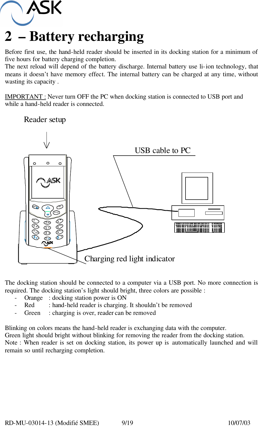
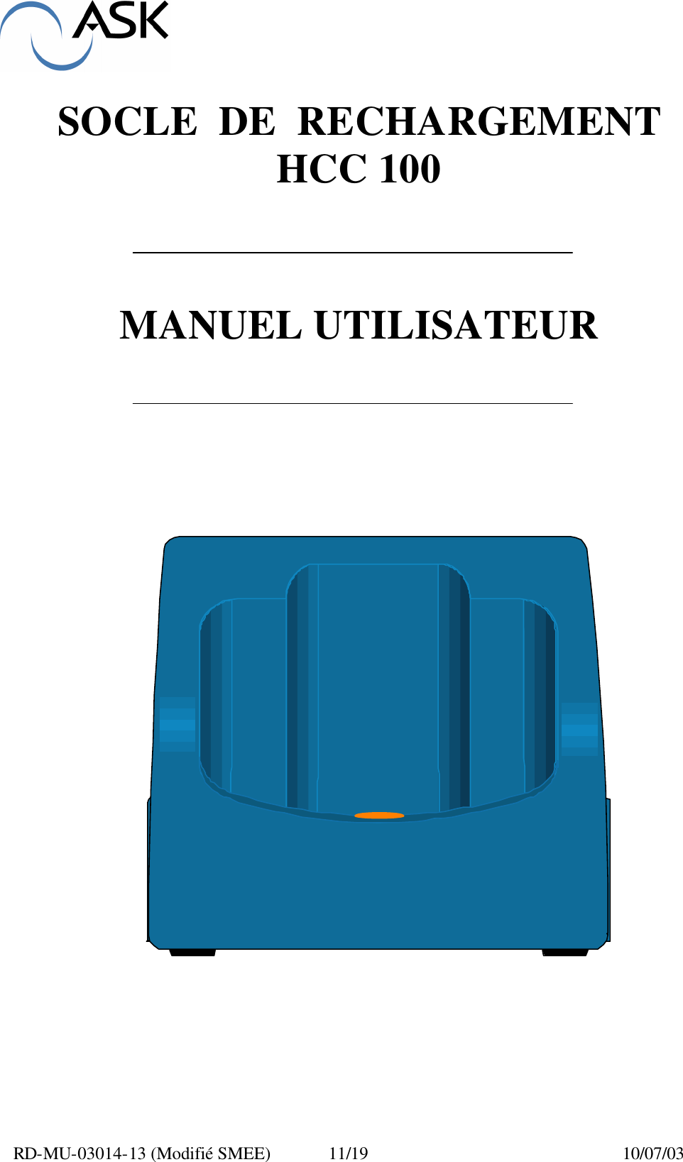
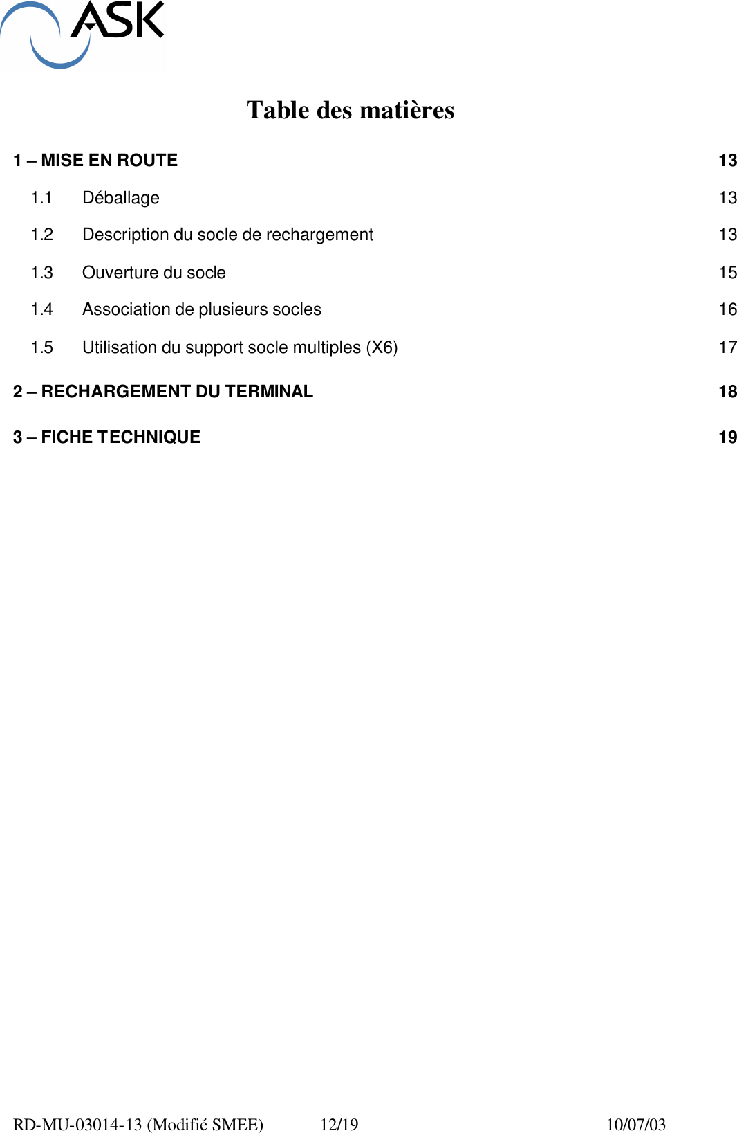
USER MANUAL HCC 100
Contents
1.
USER MANUAL HCC 100
2.
USER MANUAL HCR 800 805
USER MANUAL HCC 100
Navigation menu
Upload a User Manual
Namespaces
Wiki Guide
HTML
PDF
Info
Views
User Manual
Discussion / Help
Navigation