ASK HCRRDDE0207523 Card Reader User Manual RD MU 03014 13 Modifi SMEE
ASK Card Reader RD MU 03014 13 Modifi SMEE
ASK >
Contents
- 1. USER MANUAL HCC 100
- 2. USER MANUAL HCR 800 805
USER MANUAL HCC 100
RD-MU-03014-13 (Modifié SMEE) 1/19 10/07/03
DOCKING STATION HCC 100
USER MANUAL

RD-MU-03014-13 (Modifié SMEE) 2/19 10/07/03
FCC Compliance Statements
Class B Digital Device: This device complies with Part 15 of the FCC Rules. These
limits are designed to provide a reasonable protection against harmful interferences in a
residential installation. This equipment generates, uses and can radiate radio frequency
energy and, if not installed and used in accordance with the instructions manual, may
cause harmful interference to radio communications. However, there is no guarantee
that interference will not occur in a particular installation. If this equipment does cause
harmful interference to radio or television reception, which can be determined by turning
the equipment off and on, the user is encouraged to try the correct interference by one
of the following measures:
- Reorient or relocate the receiving antenna.
- Increase the separation between the equipment and receiver.
- Connect the equipment into an outlet on a circuit different from that to which
the receiver is connected.
- Consult an experienced radio/TV technician for help.
Caution: The manufacturer is not responsible for any radio or television interference
caused by unauthorized changes or modifications to this equipment. Unauthorized
changes or modifications could void the user’s authority to operate this equipment.
Compliance accessories: The accessories associated with this equipment are:
shielded USB cable with ferrite tube (normally supplied with the HCC 100 and attached
to it). These accessories are required to be used in order to ensure compliance with the
FFC rules.
CE Compliance statement
The ASK HCC 100 docking station is in conformity with European requirements, this
product has been assessed to the following standard:
EN 55022 / CISPR22 Class B
EN 55024 / CISPR 24
EN 60950-1 / IEC 60950-1

RD-MU-03014-13 (Modifié SMEE) 3/19 10/07/03
Table of contents
1 – FIRST USE 4
1.1 Unpacking 4
1.2 Docking station overview 4
1.3 Docking station opening 6
1.4 Grouping docking stations 7
1.5 Using docking station bay (X6) 8
2 – BATTERY RECHARGING 9
3 – TECHNICAL FEATURES 10
RD-MU-03014-13 (Modifié SMEE) 4/19 10/07/03
1 – First use
1.1 Unpacking
Check in packaging box if following items are present:
- 1 HCC 100
- 1 USB cable
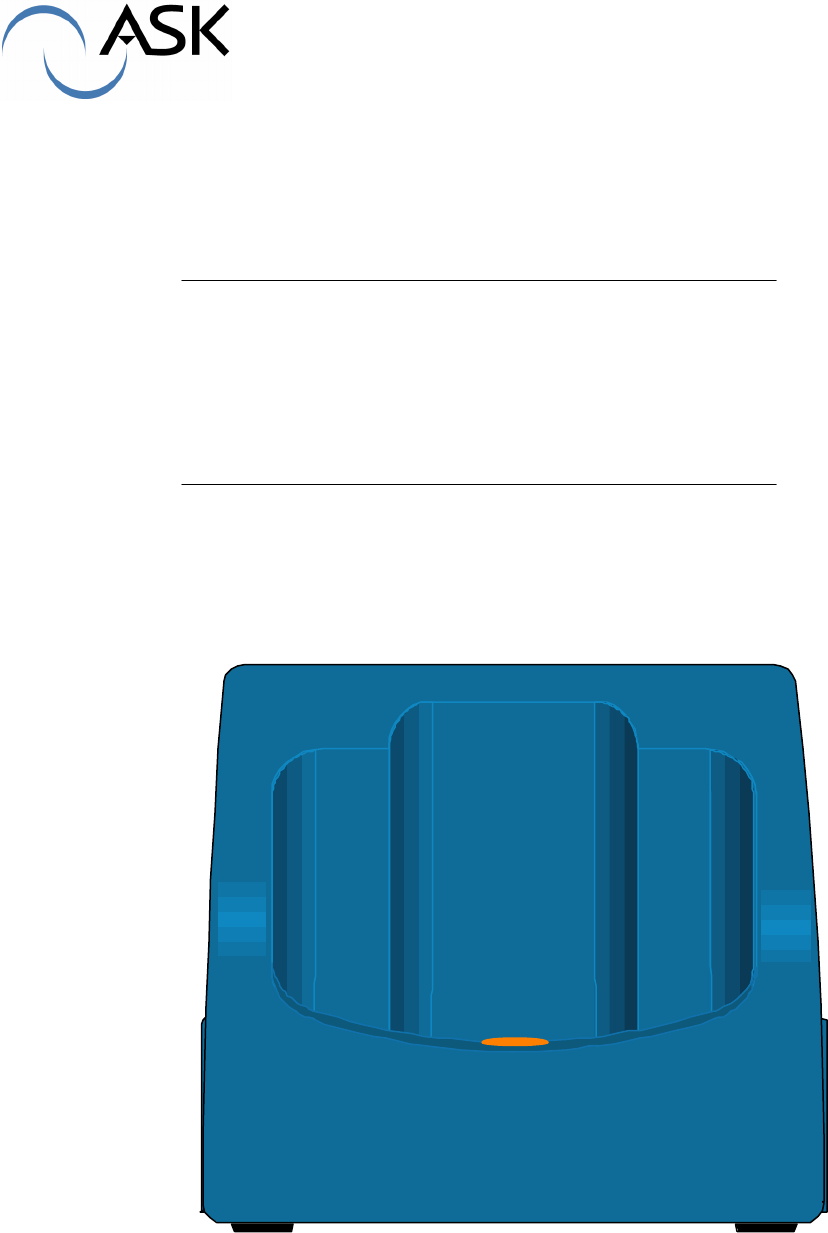
1.2 Docking station overview
The HCC 100 docking station performs the following functions:
- Physical support of the terminal
- Battery recharging
- Interface for exchange of information between the terminal and the concentrator by
USB link.
It performs USB1.1 to 115.2 kb/s serial link adaptation between PC and HCR.
It features Green / Orange / Red Led battery charge indicator.
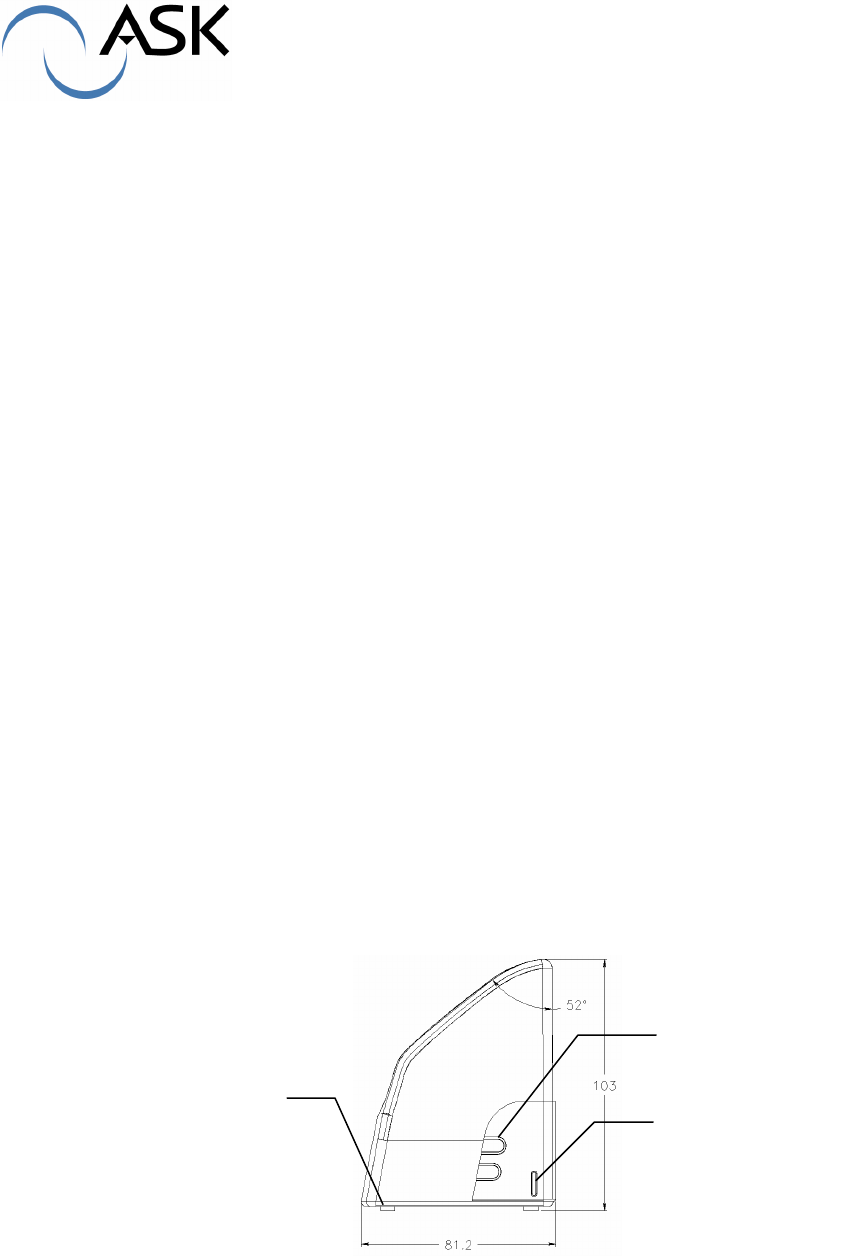
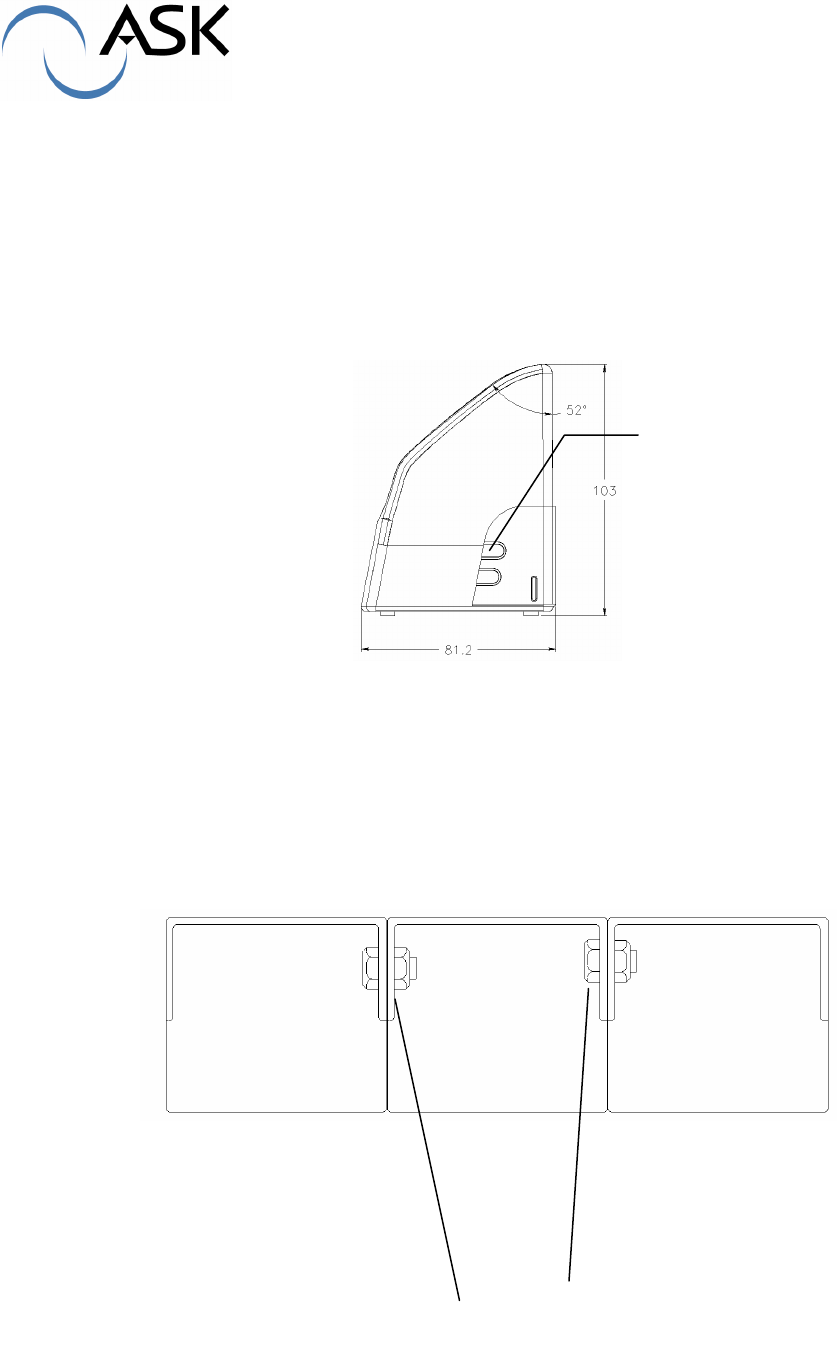
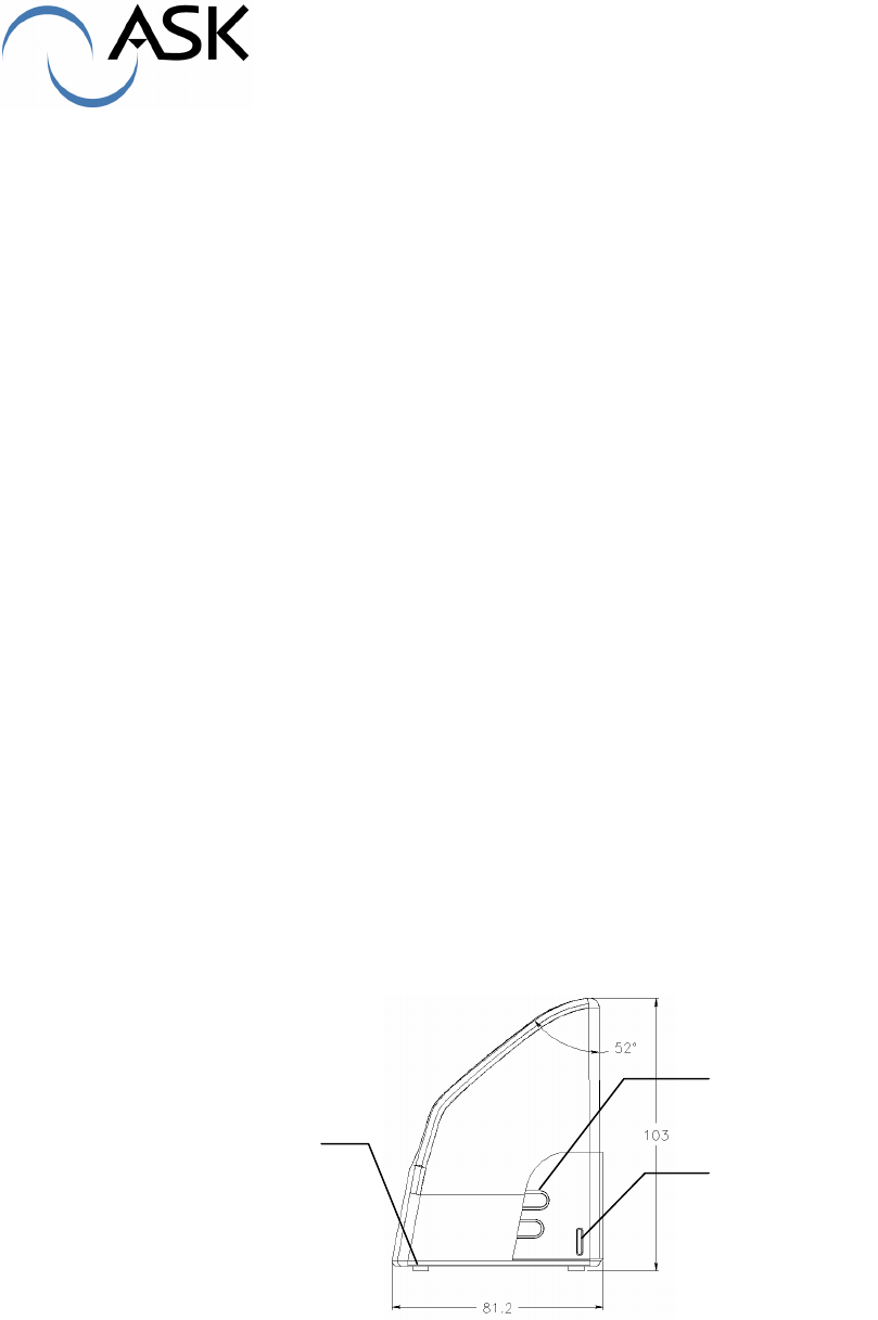
Side view:
The docking station has four adhesive feet, different holes enable setting of the terminal on a
horizontal or vertical support.
Centering guide
Precut parts
Rubber
foot
RD-MU-03014-13 (Modifié SMEE) 5/19 10/07/03
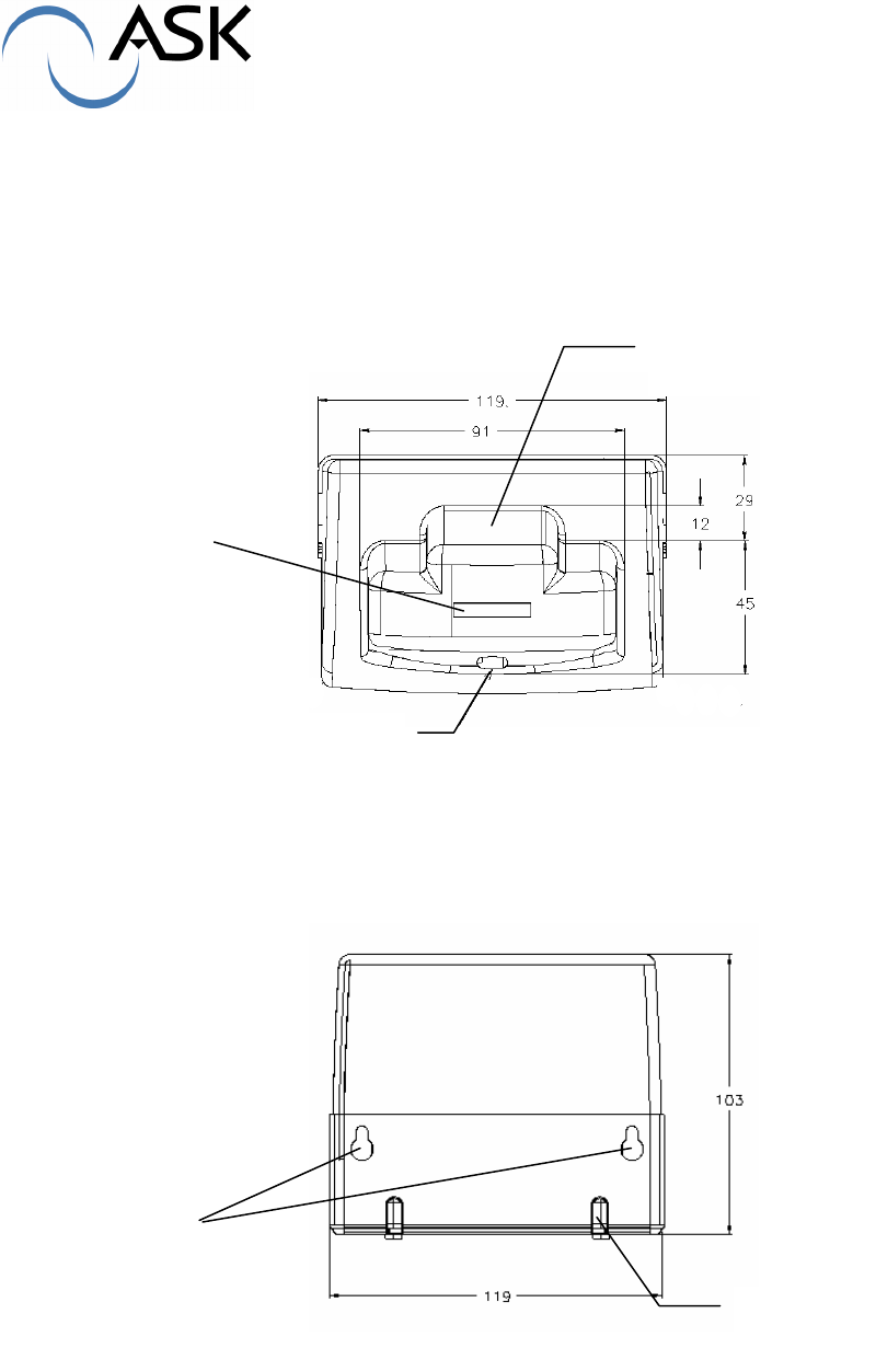
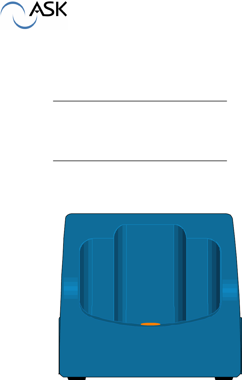
Top view :
The recharging connector is situated deep inside the docking station, in the hand-held reader
footprint.
At the front side a light with different colours provides information about recharging state.
The backside of the hand-held reader’s footprint includes a path for the strap.
Rear view :
Holes for wall installation and opening for cable are seen at the rear side of the docking station.
light
Connector
Path for
strap
Hole for wall
installation
Cable
opening
RD-MU-03014-13 (Modifié SMEE) 6/19 10/07/03
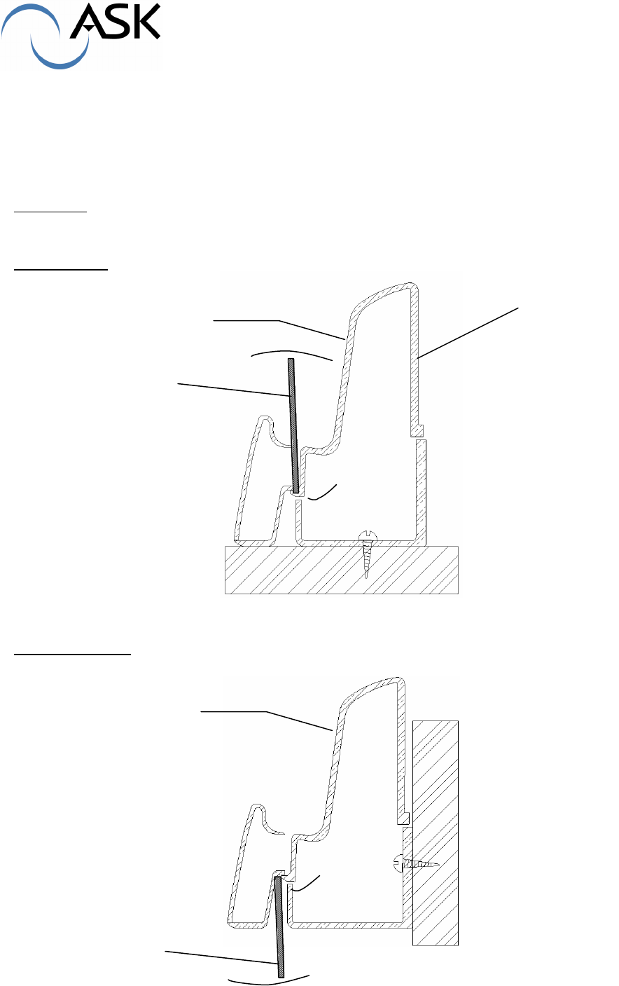
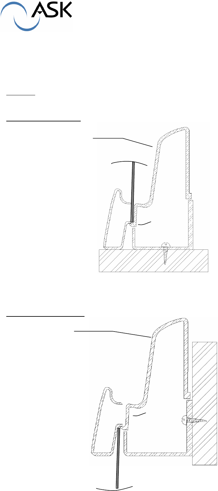
1.3 Docking station opening
The docking station is composed of two parts : the cover shell and the chassis
They are maintained together by self-locking. Unlocking can be done by action on the top of the
cover or on the bottom of the chassis. The way depends on the setting of the docking station
(table top or wall).
Operating : With a flat screwdriver, push successively on the internal locking ergot, while cover
shell is pushed back
Top opening :
cutaway drawing
Bottom opening :
cutaway drawing
Push back
Push back
screwdriver
screwdriver
Cover shell
RD-MU-03014-13 (Modifié SMEE) 7/19 10/07/03
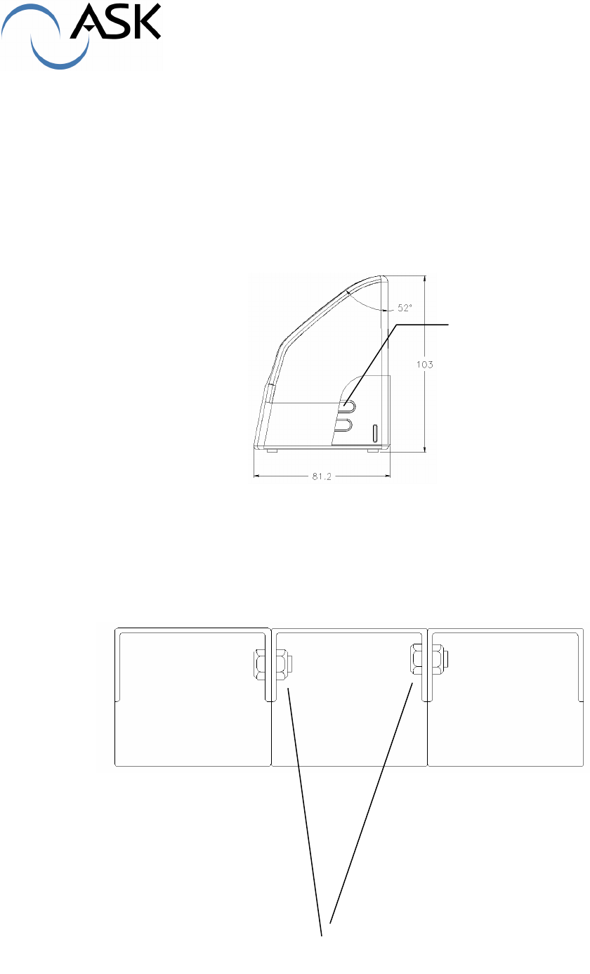
1.4 Grouping docking stations
HCC shelves own male centring guide at the left and female centring guide at the right which
allow the HCC positioning when two or more HCC are associated.
Lateral precut footprint can be broken in order to offer a path for fixing screws. This way,
docking stations can be tight with M4x12 screw and nut.
Precut
footprint
Screw and nut
between HCC
RD-MU-03014-13 (Modifié SMEE) 8/19 10/07/03
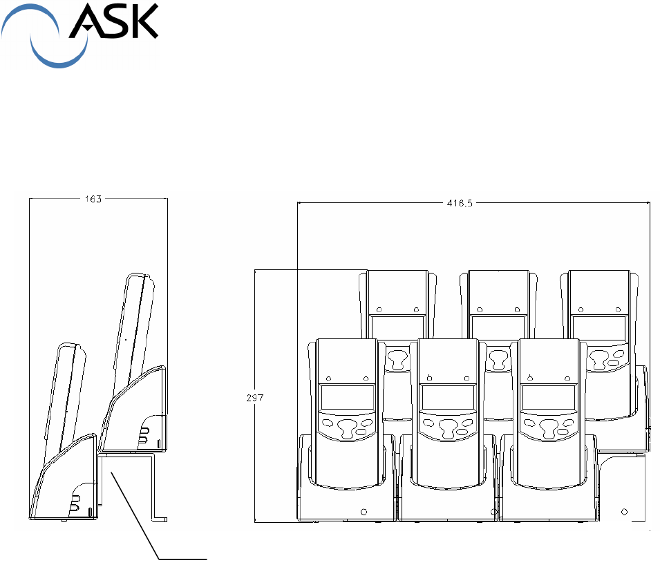
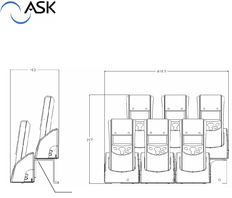
1.5 Using docking station bay (X6)
ASK can provide optional bays, they support up to 6 docking stations. These bays can easily be
in juxtaposition, this allows the associated setting of several docking stations (6, 12, 18,…).
The support can be either set on a wall or on a table
Support
RD-MU-03014-13 (Modifié SMEE) 9/19 10/07/03
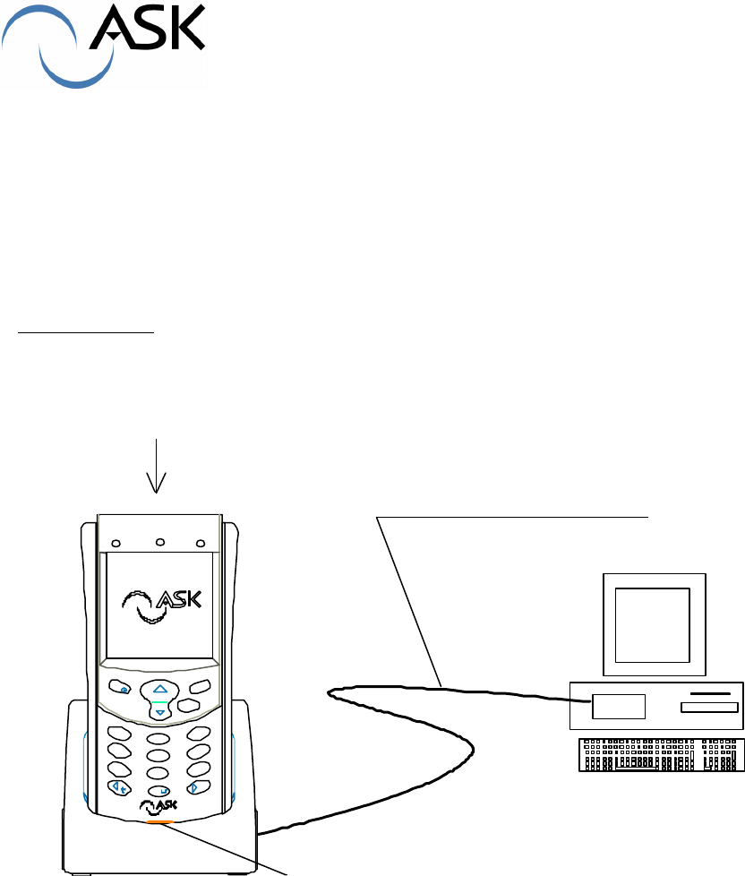
2 – Battery recharging
Before first use, the hand-held reader should be inserted in its docking station for a minimum of
five hours for battery charging completion.
The next reload will depend of the battery discharge. Internal battery use li-ion technology, that
means it doesn’t have memory effect. The internal battery can be charged at any time, without
wasting its capacity .
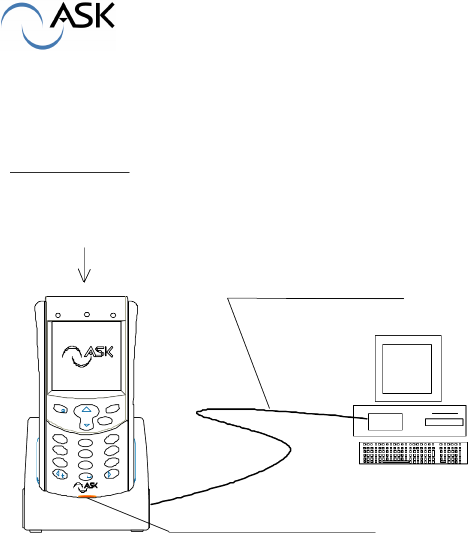
IMPORTANT : Never turn OFF the PC when docking station is connected to USB port and
while a hand-held reader is connected.
The docking station should be connected to a computer via a USB port. No more connection is
required. The docking station’s light should bright, three colors are possible :
- Orange : docking station power is ON
- Red : hand-held reader is charging. It shouldn’t be removed
- Green : charging is over, reader can be removed
Blinking on colors means the hand-held reader is exchanging data with the computer.
Green light should bright without blinking for removing the reader from the docking station.
Note : When reader is set on docking station, its power up is automatically launched and will
remain so until recharging completion.
Me nu OK
Annul
1
2
3
456
789
0
abc
def
ghijkl
mno
pqrstuv
wxyz
#
Reader setup
USB cable to PC
Charging red light indicator

RD-MU-03014-13 (Modifié SMEE) 10/19 10/07/03
3 – Technical features
It consists of 2 main parts
- Cover shell : ABS-PC material
- Chassis part enabling setting of the terminal : ABS-PC material and 2 metallic ballast
on a horizontal or vertical support.
- Adhesive feet
- USB A/B 2m cable attached to the docking station
Temperature rating :
Operating temperature range: +23°F to +131°F (-5°C to +55°C)
Battery recharge temperature range: +32°F to +113°F ( 0°C to + 45°C)
Storage temperature range : -4°F to +140°F (-20°C to +60°C)
Case characteristics :
- Length : 4.72 in (120 mm)
- width : 3.19 in ( 81 mm)
- height : 4.09 in (104 mm)
- weight : 310g with ballast
RD-MU-03014-13 (Modifié SMEE) 11/19 10/07/03
SOCLE DE RECHARGEMENT
HCC 100
MANUEL UTILISATEUR

RD-MU-03014-13 (Modifié SMEE) 12/19 10/07/03
Table des matières
1 – MISE EN ROUTE 13
1.1 Déballage 13
1.2 Description du socle de rechargement 13
1.3 Ouverture du socle 15
1.4 Association de plusieurs socles 16
1.5 Utilisation du support socle multiples (X6) 17
2 – RECHARGEMENT DU TERMINAL 18
3 – FICHE TECHNIQUE 19
RD-MU-03014-13 (Modifié SMEE) 13/19 10/07/03
1 – Mise en route
1.1 Déballage
Vérifier dans l’emballage la présence des composants suivants :
-Un socle de rechargement
-Un câble de connexion USB
1.2 Description du socle de rechargement HCC 100
Le support de rechargement assure les fonctions suivantes:
- Support de dépose du terminal portable
- Recharge de la batterie
- Echange d’informations entre le terminal et le concentrateur via une liaison
USB.
Il assure une liaison série USB1.1 à 115.2 kb/s entre le PC et le HCR.
Vue de côté :
Le socle possède quatre pieds caoutchouc, deux perçages de fixation en partie basse pour un
montage sur un plan de travail et deux perçages en partie arrière pour une fixation au mur.
Plot de
centrage
Zones
prédécoupées
4 pieds
caoutchouc

RD-MU-03014-13 (Modifié SMEE) 14/19 10/07/03
Vue de dessus :
Le connecteur de rechargement se trouve au fond du logement du terminal HCR dans le socle.
Sur le devant un voyant avec plusieurs couleurs indique l’état de rechargement.
A l’arrière du logement du terminal HCR , un dégagement est prévu pour le passage de la sangle.
Vue de dos :
Les trous de fixation murale et les passages de câble sont visibles à l’arrière du socle.
Voyant
Connecteur
Dégagement
pour sangle
Points de
fixation murale
Passa
ge du
câble
RD-MU-03014-13 (Modifié SMEE) 15/19 10/07/03
1.3 Ouverture du socle
Le socle est composé de deux parties : le capot de socle et le fond de socle. Ils sont assemblés
par clipsages. Le déclipsage peut s’opérer par le dessus ou le dessous du socle selon sa fixation
(murale ou sur une table).
Méthode : à l’aide d’un tournevis plat agir successivement sur l’un et l’autre clip en maintenant
une poussée vers l’arrière sur capot supérieur.
Ouverture par le dessus :
vue en coupe du socle
Ouverture par le dessous :
Poussée vers
l’arrière
Poussée vers
l’arrière
RD-MU-03014-13 (Modifié SMEE) 16/19 10/07/03
1.4 Association de plusieurs socles
Les fonds de socles possèdent des points de centrage mâle à gauche et femelle à droite qui
permettent de positionner les socles en batterie.
Des amorces de ruptures latérales permettent de lier les socles entre eux au moyen de boulons
type M4X12
vue de dessus
Zones à
découper
Vis de fixation
entre socles
RD-MU-03014-13 (Modifié SMEE) 17/19 10/07/03
1.5 Utilisation du support socle multiples (X6)
ASK peut fournir en option des supports pour 6 socles juxtaposables , ce qui facilite la mise en
batterie d’un nombre important d’appareils (6,12,18,…).
Le support peut se fixer indifféremment au mur ou sur une table.
Support
RD-MU-03014-13 (Modifié SMEE) 18/19 10/07/03
2 - Rechargement du Terminal
Avant la première utilisation le terminal doit être placé sur son socle pour une durée minimum de
cinq heures afin d’effectuer la charge complète de la batterie. Les recharges suivantes
dépendront du niveau de décharge de la batterie. Celle-ci étant de technologie Li-ion , elle ne
possède pas d’effet mémoire et peut être rechargée à tout moment sans dégradation de sa
capacité.
NOTE IMPORTANTE : Ne jamais éteindre le PC quand le terminal portable est sur un socle
connecté par la liaison USB
Le socle doit être raccordé à la prise USB d’un ordinateur. Aucune autre connexion n’est
nécessaire. Le voyant du socle doit être allumé et possède trois couleurs :
- Orange : le socle est alimenté
- Rouge : le terminal est en phase de chargement, il ne doit pas être retiré
- Vert : le terminal est chargé, il peut être retiré
Des clignotements sur les couleurs indiquent que le terminal est en train de communiquer avec le
PC. Attendre la couleur verte fixe pour retirer le terminal du socle.
Nota : Lorsque le terminal est placé sur son socle, sa mise en marche est déclenchée
automatiquement et sera maintenue durant toute la durée du rechargement.
Menu OK
Annul
1
2
3
456
789
0
abc
def
ghijkl
mno
pqrstuv
wxyz
#
Mise en place du terminal
Liaison au PC par cable USB
Voyant indicateur de charge

RD-MU-03014-13 (Modifié SMEE) 19/19 10/07/03
3 - Fiche technique
. Le socle est constitué de deux parties:
- capot de socle : matière plastique ABS-PC
- Fond de socle qui permet la fixation sur un support vertical ou horizontal
matière plastique ABS-PC avec deux lests métalliques.
et
- Quatre pieds adhésifs
- Cable USB de 2m raccordé au socle de rechargement.
Conditions d’utilisation :
Température d’utilisation : -5°C à +55°C
Température de rechargement : 0°C à + 45°C
Température de stockage : -20°C à +60°C
Caractéristiques générales :
Les coques sont en ABS-PC antichoc. La façade semi-transparente en poly-carbonate. La vitre
de protection de l’écran est en PMMA
- Longueur : mm
- Largeur : 84 mm (zone de préhension), 92 mm (zone de lecture)
- Epaisseur : 27 mm à 33 mm
- Poids : 311g avec lest