ASSALOY Global Solutions Norway AS PCBA9002 RF Module User Manual AA logo white eps
ASSA ABLOY Hospitality AS RF Module AA logo white eps
user manual

Upgrade Manual
RF-Online Safe

October 11, 2011 Page 2 of 22 66 3081 018-4
FCC/IC approval
This device complies with Part 15 of the FCC Rules. Operation is subject to the following two
conditions: (1) this device may not cause harmful interference, and (2) this device must accept
any interference received, including interference that may cause undesired operation.
Changes or modifications to the equipment not expressly approved by the party responsible for
compliance could void the user’s authority to operate the equipment.
Note: This equipment has been tested and found to comply with the limits for a Class B digital
device, pursuant to Part 15 of the FCC Rules. These limits are designed to provide reasonable
protection against harmful interference in a residential installation. This equipment generates,
uses and can radiate radio frequency energy and, if not installed and used in accordance with
the instructions, may cause harmful interference to radio communications. However, there is
no guarantee that interference will not occur in a particular installation.
If this equipment does cause harmful interference to radio or television reception, which can
be determined by turning the equipment off and on, the user is encouraged to try to correct
the interference by one or more of the following measures:
- Reorient or relocate the receiving antenna.
- Increase the separation between the equipment and receiver.
- Connect the equipment into an outlet on a circuit different from
that to which the receiver is connected.
- Consult the dealer or an experienced radio/TV technician for help.
This device complies with Industry Canada licence-exempt RSS standard(s). Operation
is subject to the following two conditions: (1) this device may not cause interference, and
(2) this device must accept any interference, including interference that may cause undesired
operation of the device.
Le présent appareil est conforme aux CNR d'Industrie Canada applicables aux appareils radio
exempts de licence. L'exploitation est autorisée aux deux conditions suivantes: (1) l'appareil
ne doit pas produire de brouillage, et (2) l'utilisateur de l'appareil doit accepter tout brouillage
radioélectrique subi, même si le brouillage est susceptible d'en compromettre le fonctionnement.
ICES-003 statement
This Class B digital apparatus complies with Canadian ICES-003.
Cet appareil numérique de la classe B est conforme à la norme NMB-003 du Canada.
The FCC/IC number for the safe endnode is FCC Y7VPCBA9002 / IC 9514A-Y7V

October 11, 2011 Page 3 of 22 66 3081 018-4
Copyrights
The information in this document is subject to change without further notice. No part of this document
may be reproduced or transmitted in any form or by any means, electronic or mechanical, for any
purpose, without the express written permission of VingCard Elsafe AS.
Table of contents
1
INTRODUCTION.............................................................................................................................. 4
2
UPGRADE KIT ................................................................................................................................. 4
2.1
Safe preparation............................................................................................................................. 5
2.2
Cable connection ........................................................................................................................... 6
2.2.1
Connecting RFOI with endnode and outside PCB................................................................. 6
2.2.2
Connecting RFOI with inside PCB........................................................................................ 8
2.2.3
Connecting RFOI with front board ........................................................................................ 8
3
RF-ONLINE SAFE USAGE.............................................................................................................. 9
3.1
Connecting an RF-Online safe to the network............................................................................... 9
3.1.1 Starting SysMon..................................................................................................................... 9
3.1.2 Opening the concerned gateway or router for joining............................................................ 9
3.1.3 Setting the safe in discovery mode...................................................................................... 10
3.2 Disconnecting a safe from the network ....................................................................................... 12
3.3 Reconnecting a safe to the network............................................................................................. 12
4
SETTINGS AND SUPERVISION IN VISIONLINE...................................................................... 13
4.1 Enabling online functionality for safes........................................................................................ 13
4.1.1 Installing an option in VISIONLINE ................................................................................... 13
4.1.2 Settings at Tools/Options/Online/Safes................................................................................ 14
4.1
Safes list in VISIONLINE........................................................................................................... 15
4.3 Safes list in SysMon .................................................................................................................... 15
4.4 Events .......................................................................................................................................... 16
4.5 Alarms.......................................................................................................................................... 17
4.6 Commands for safes..................................................................................................................... 18
4.6.1 Get info................................................................................................................................. 18
4.6.2 Set time................................................................................................................................. 19
4.6.3 Ping....................................................................................................................................... 19
4.6.4 Get activation code............................................................................................................... 19
4.6.5 Remove................................................................................................................................. 19
4.7
Renting a safe .............................................................................................................................. 20
4.7.1
At check-out......................................................................................................................... 20
5 TROUBLESHOOTING..................................................................................................................... 21
6 SERVICE COMMANDS................................................................................................................... 21
October 11, 2011 Page 4 of 22 66 3081 018-4
1 Introduction
This document describes
• how to upgrade an existing Sentinel Digital Ph III safe to a Sentinel Digital Ph III RF-Online safe
• how to use the VISIONLINE software together with RF-Online safes
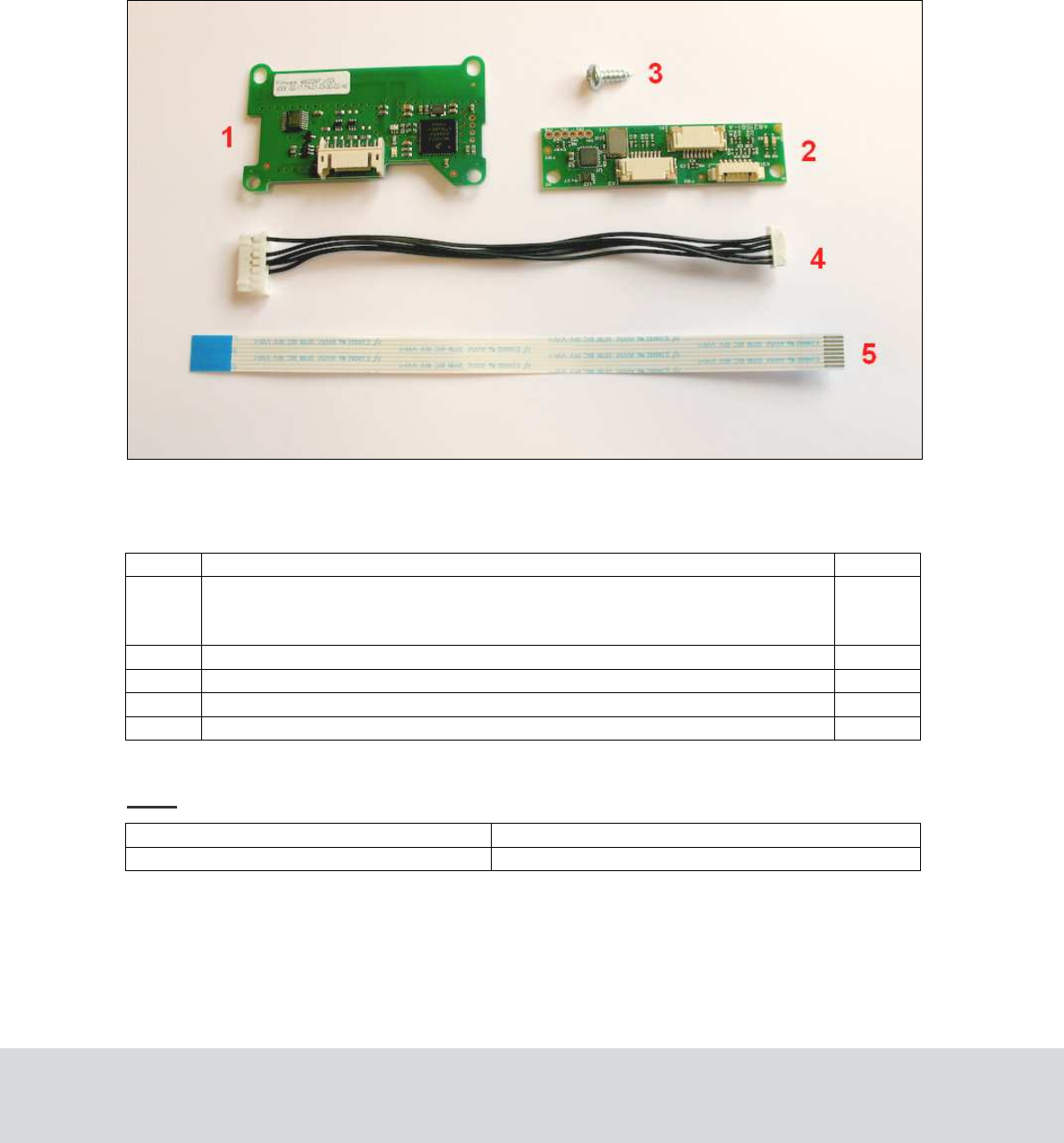
2 Upgrade kit
Upgrade kit necessary for an RF-Online upgrade
No. Description Pcs
1
ZigBee Endnode (article number 4821930; the endnode is however not sold
separately on this number but only as a part of RF-Online Communication Kit
PHIII, see article number below)
1
2
RF-Online Interface (RFOI)
1
3
Screw
1
4
Cable RFOI-Endnode
1
5
Flex cable RFOI-Front board
1
Note: The parts above are available as a kit with article number as below.
Art. No Description
252-846KIT
RF-Online Communication Kit PHIII
October 11, 2011 Page 5 of 22 66 3081 018-4
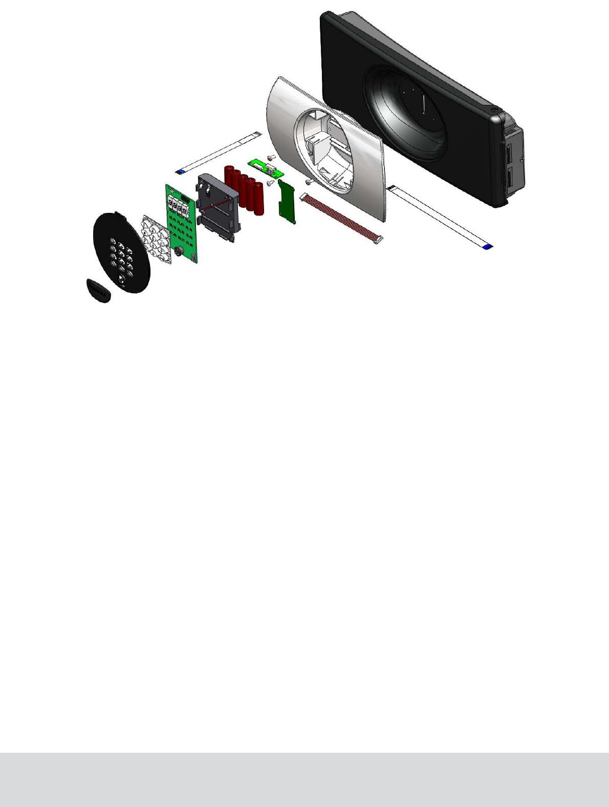
Exploded view of a Sentinel Ph III RF-Online safe
2.1 Safe preparation
For a smooth upgrade operation, follow the steps below before connecting the RF-Online kit to the
existing safe:
1. Open the front cover and remove one battery from the battery cartridge.
2. Press and hold the Reset button down for at last 3 seconds.
3. Disconnect the flat flex cable from the front board.
4. The safe is now ready for mounting of RF-Online components.
October 11, 2011 Page 6 of 22 66 3081 018-4
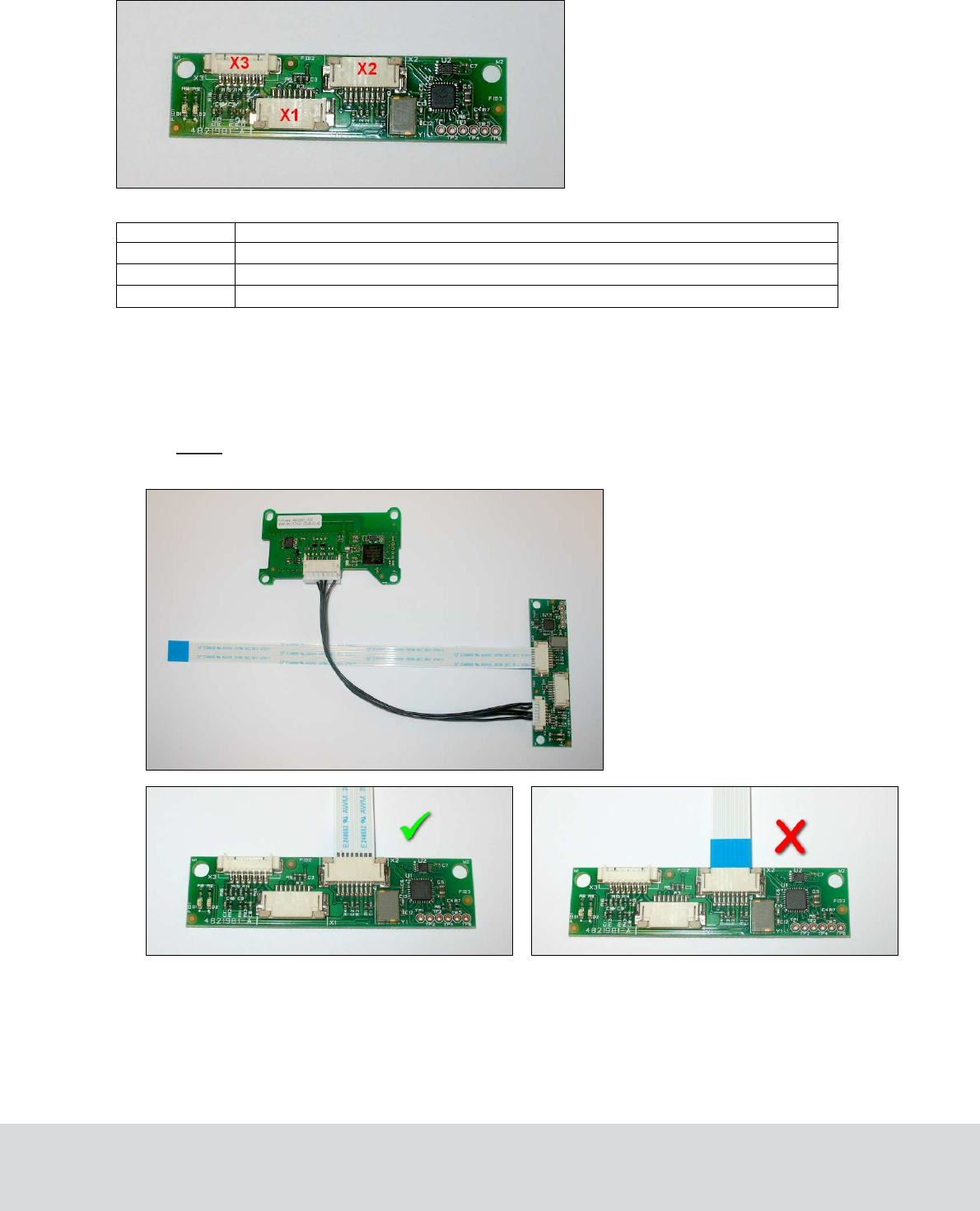
2.2 Cable connection
The RFOI has three connectors: X1, X2 and X3.
Connector Use
X1 Connects RFOI and inside PCB, using existing flex cable
X2 Connects RFOI and outside PCB, using short flex cable
X3 Connects RFOI and endnode
,
using 5-wire cable
2.2.1 Connecting RFOI with endnode and outside PCB
1. Connect the 5-wire cable to the endnode.
2. Connect the other end of the cable to the RFOI; socket X3.
3. Connect the short flex cable to the RFOI; socket X2.
Note: Make sure to connect the short flex cable between RFOI and outside PCB in the
correct way; see picture below for correct connection.
Correct connection
Wrong
connection
October 11, 2011 Page 7 of 22 66 3081 018-4
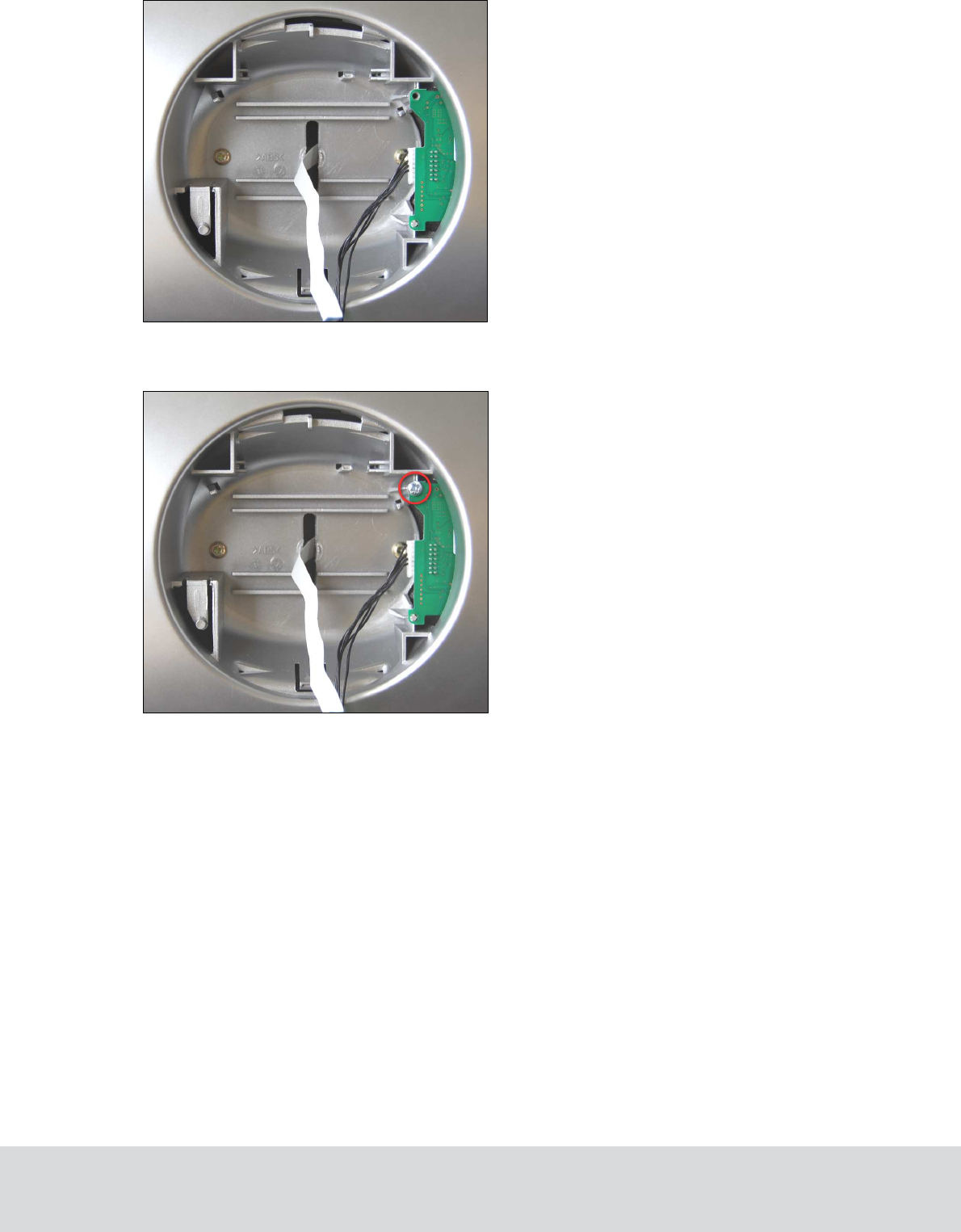
4. Insert the endnode firmly as shown in the picture below.
5. Fasten the endnode with one screw; see picture below.
October 11, 2011 Page 8 of 22 66 3081 018-4
2.2.2 Connecting RFOI with inside PCB
1. Make sure that the 5-wire cable between endnode and RFOI is connected; see section 2.2.1
for details.
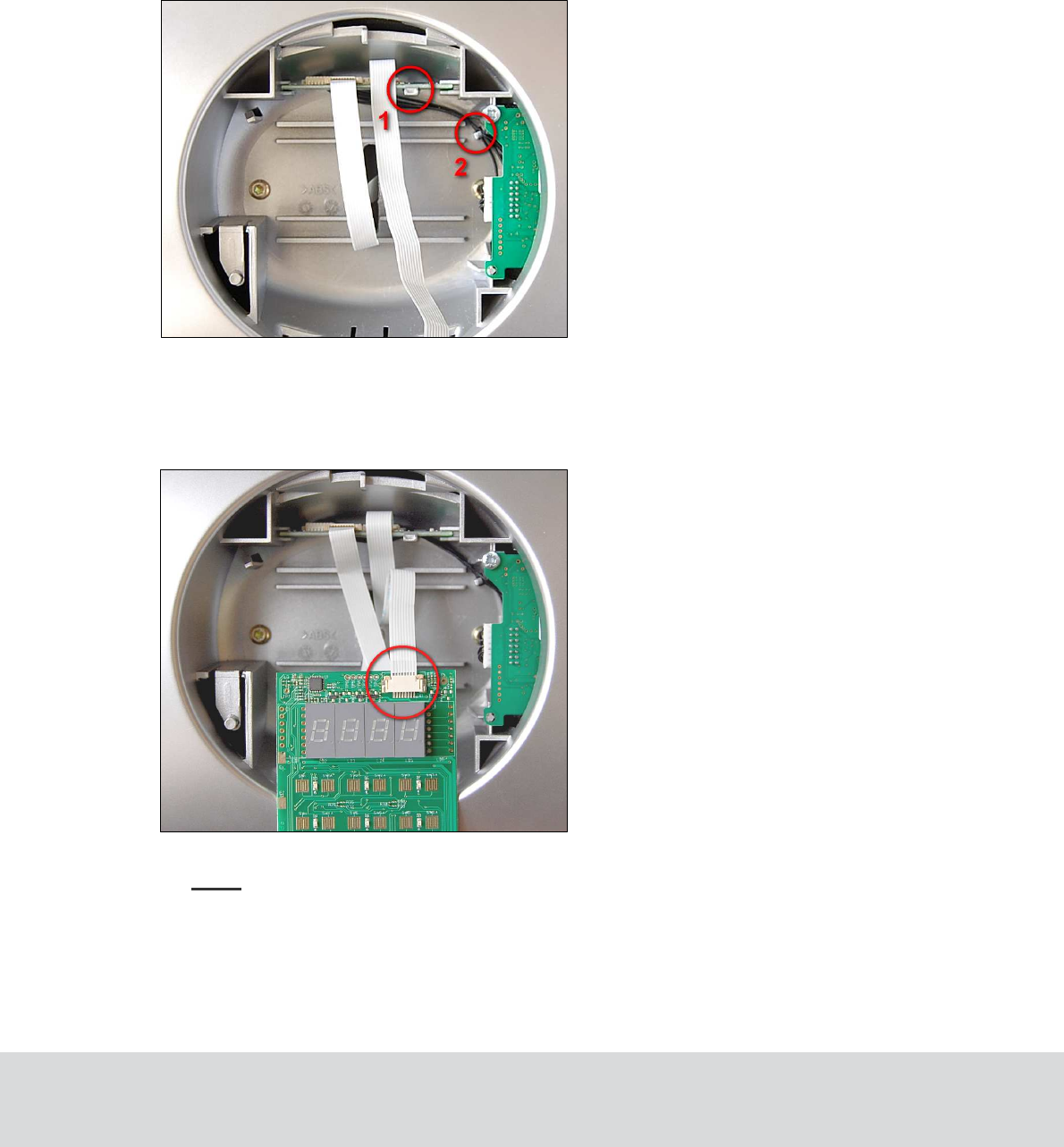
2. Insert the RFOI firmly until the snap will hold it; see 1 in the following picture. Be careful
about the cable between endnode and RFOI - the cable must be placed below the RFOI board
and behind the supporting tower; see 2 in the following picture. The flex cable connected to
the X2 connector should be bended upwards.
3. Connect the previously disconnected flex cable from the inside of the safe to the connector X1
on the RFOI board.
2.2.3 Connecting RFOI with front board
1. Connect the flex cable from the RFOI socket X2 to the front board.
2. When the cable is fitted properly, the front cover of the safe can be closed.
Note: Do not forget to insert the battery that was removed according to section 2.1.
October 11, 2011 Page 9 of 22 66 3081 018-4
3 RF-Online safe usage
Note: The RF-Online safe can only be connected to an existing ZigBee network.
3.1 Connecting an RF-Online safe to the network
Note: Before connecting the safe to the network, the safe must have been commissioned.
To allow the safe to join the ZigBee network, the concerned ZigBee router or gateway must be ‘open’.
This is performed in the software SysMon (System Monitor); see 3.1.1. Follow the steps in sections 3.1.2
and 3.1.3 for joining the safe to the network.
3.1.1 Starting SysMon
1. Double click on SysMon.exe in the VISIONLINE installation folder.
2. Log on with the same user name and password as for VISIONLINE.
Tip: Create a shortcut to SysMon.exe since this program will be extensively used.
3.1.2 Opening the concerned gateway or router for joining
1. In the SysMon menu View, select ZigBee; the ZigBee Network window which is shown.
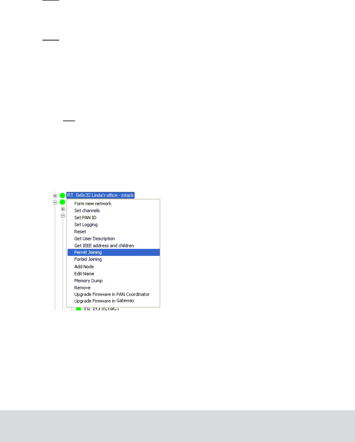
2. Right click on the applicable gateway/router in the ZigBee Network window and select
Permit Joining. The gateway/router is now ‘open’. It will remain in this status for
approximately 15 minutes or until a forbid join command is executed.
October 11, 2011 Page 10 of 22 66 3081 018-4
3.1.3 Setting the safe in discovery mode
To be able to connect to the open router or gateway, the RF-Online safe must be set in discovery mode:
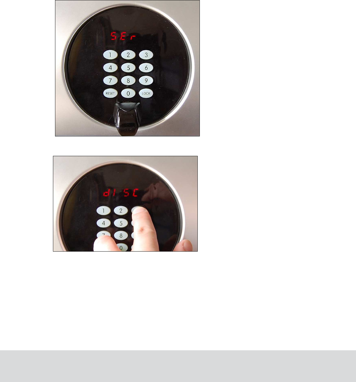
1. With the gateway/router open from the steps performed in section 3.1.2, connect the Universal
Safe Interface (PinKey, ElKey or IR interface) to the service socket of the safe. Depending on
what interface that is used, the display of the safe will show
•
‘
Ser’ (if PinKey is used)
• ‘Ir’ (if the IR interface is used)
• ‘Open’ (if ElKey is used)
2. Press and hold the Reset and 3 buttons down simultaneously. ‘dISC’ should appear on the display.
3. Release both buttons; the safe is now in discovery mode.
4. Wait for a couple of seconds and then press and hold the Reset and 5 buttons downsimultaneously.
October 11, 2011 Page 11 of 22 66 3081 018-4
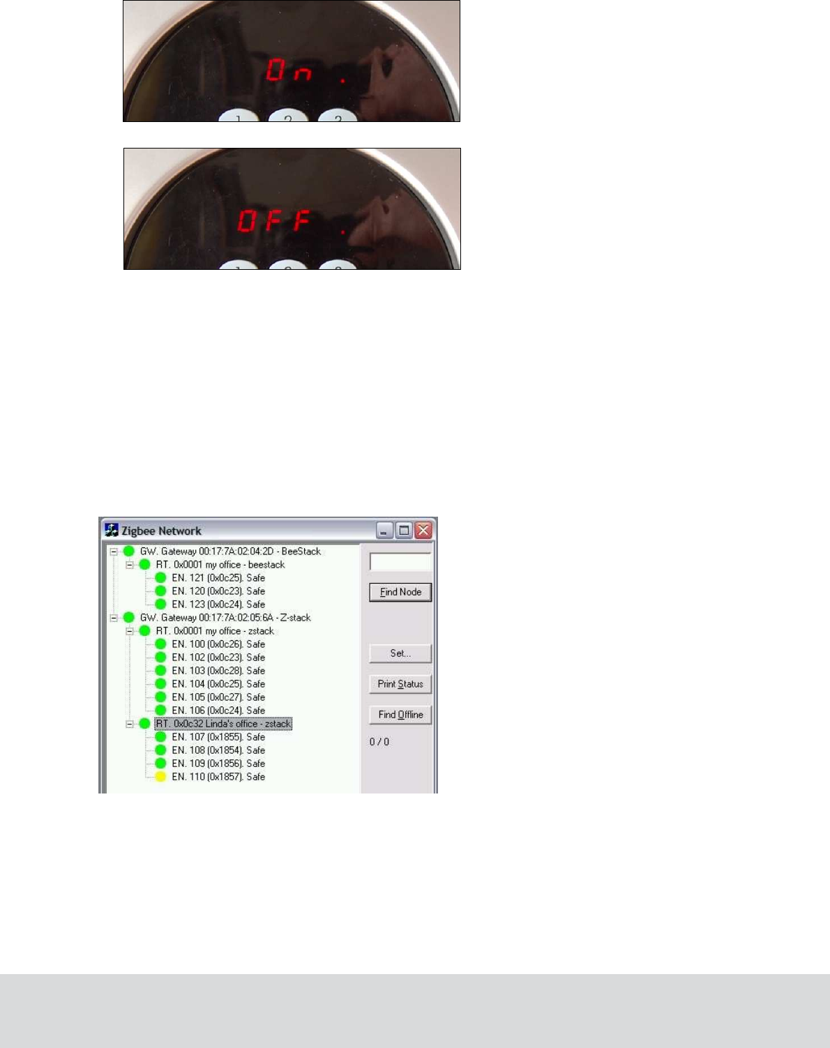
5. Depending on the connection status of the safe, it will display either ‘On .’ or ‘OFF .’.
The ‘On .’ status indicates that the safe is connected to the ZigBee network. If ‘On .’ is displayed,
the safe interface (PinKey, ElKey or IR) can be removed from the service socket.After that, the safe
should appear in the ZigBee Network window of SysMon (System Monitor) with the room number
that was set during the commissioning.
If the signal to the ZigBee network is weak ‘OFF .’on the safe display), it might be necessary to repeat
the procedure of connecting the safe to the ZigBee network; see section 3.1.2. The endnode must then
be set in discovery mode again according to steps 1-3 above.
The picture below shows a sample of the ZigBee network view, with safes connected to three
different routers.
October 11, 2011 Page 12 of 22 66 3081 018-4
3.2 Disconnecting a safe from the network
If the RF-Online functionality in a safe needs to be switched off, e.g. when the safe should be moved
from one room to another, follow the steps below:
1. Connect the safe interface to the service socket.
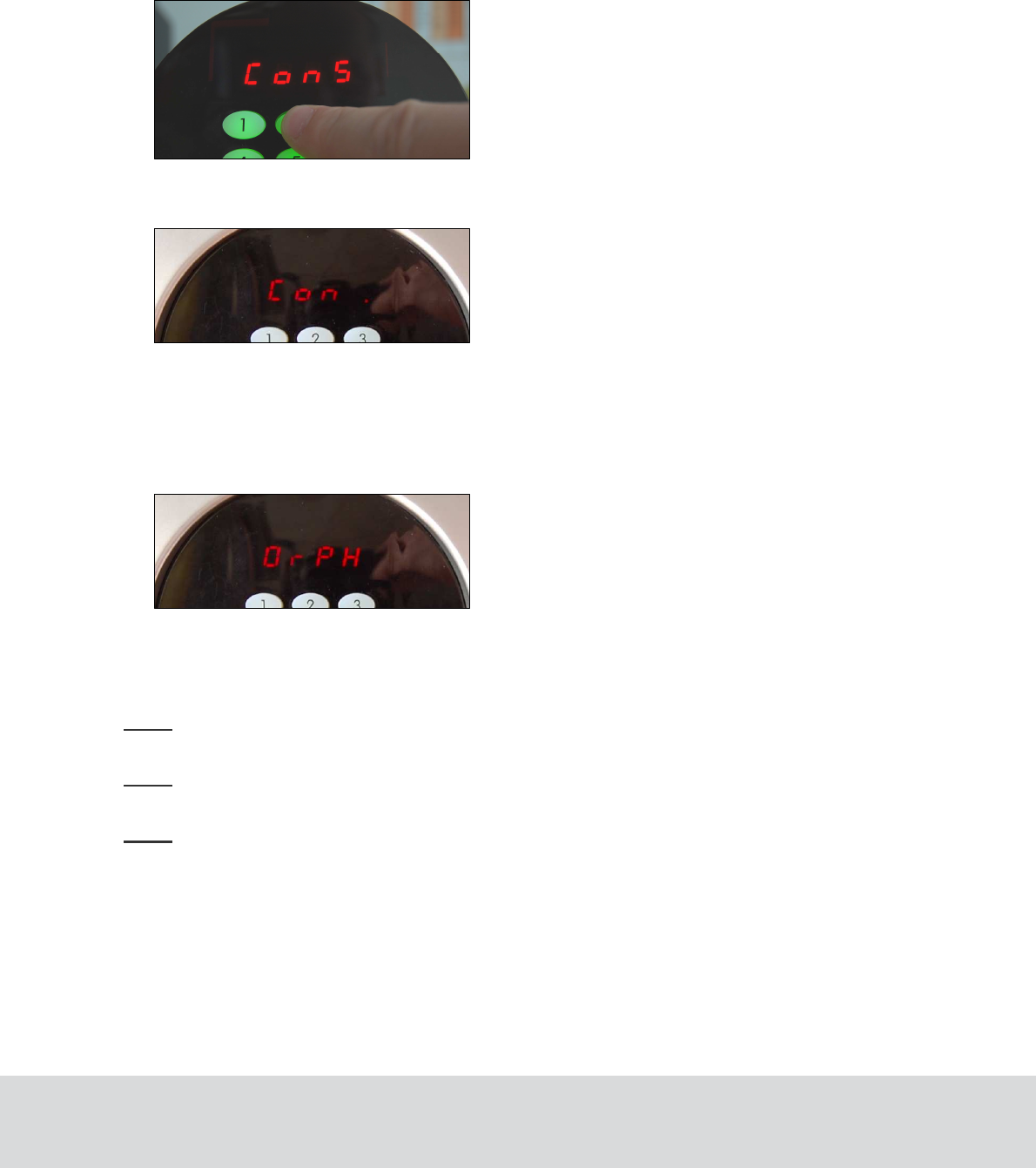
2. Press the buttons Reset and 2 and hold them down for a moment.
3. The safe display will say ‘ConS’. That means that construction mode has been activated
(which will reduce the battery consumption). The radio in the safe is turned off.
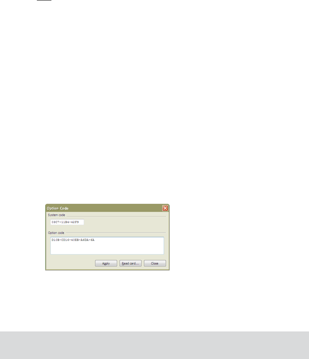
4. To verify that the radio is turned off, press and hold the Reset
and 5 buttons down. The safe
display will say ‘Con .’
3.3 Reconnecting a safe to the network
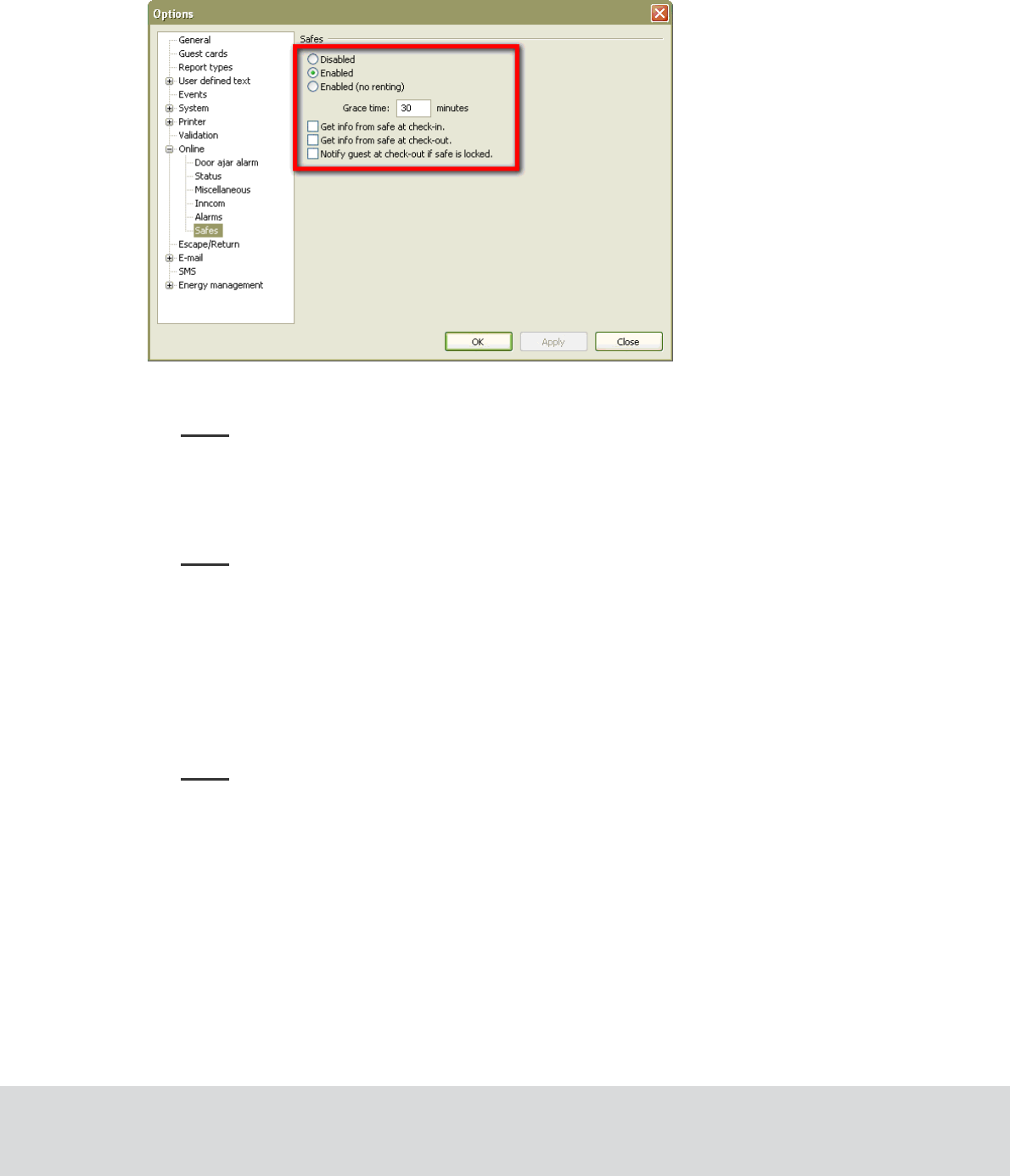
Before connecting the safe to the ZigBee network again, the RF-Online functionality should be turned on.
1. Connect the safe interface to the service socket.
2. Press and hold the Reset and 4 buttons down. The safe display will say “OrPH” (orphan join).
3. To verify that the safe is connected to the network again, check its status by pressing and
holding the Reset
and 5
buttons down. If ‘On .’ is shown on the display, the safe is
connected. If ‘Con .’ is shown, the safe is still in construction mode.
Note: Making a cold start on the safe, e.g. by replacing the battery, will also set the safe in orphan
join mode.
Note: If the front or CPU board of the safe has been exchanged, an orphan join should be made
according to the steps above.
Note: If the endnode of a safe has been exchanged, a discovery must be done according to section 3.1.3.
October 11, 2011 Page 13 of 22 66 3081 018-4
4 Settings and supervision in VISIONLINE
Before starting any work in VISIONLINE, the online functionality for safes must be enabled
in the software.
Note: VISIONLINE 1.10.0 or higher is required.
4.1 Enabling online functionality for safes
Online functionality for safes require that the VISIONLINE software options Online and
In-room safes are set; see section 4.1.1.
Once the options have been set in the software, different alternatives for the safes are available at
Tools/Options/Online/Safes; see section 4.1.2.
4.1.1 Installing an option in VISIONLINE
If the Online and In-room safes options were ordered together with the VISIONLINE software, they are
included in the VISIONLINE license code and will be set in the software when the license code is entered.
If the options should be added to the system at a later occasion, when the license code has already been
entered and system ID is therefore set, an option code is used instead. Several software options can be
included in one option code. An operator with the authority to handle option codes must be logged on.
Normally, options are set by the system manager or the distributor.
When ordering the option, the system code must be communicated to the ordering department:
1. Double click on
System settings
under the
Reports
tab in the navigation window to find the
system code.
System settings
is available even if you are not logged on.
2. Communicate your system code to the order department; see order acknowledgement for phone
number and e-mail address. The system code can also be entered in the Ordering web page when
making the order.
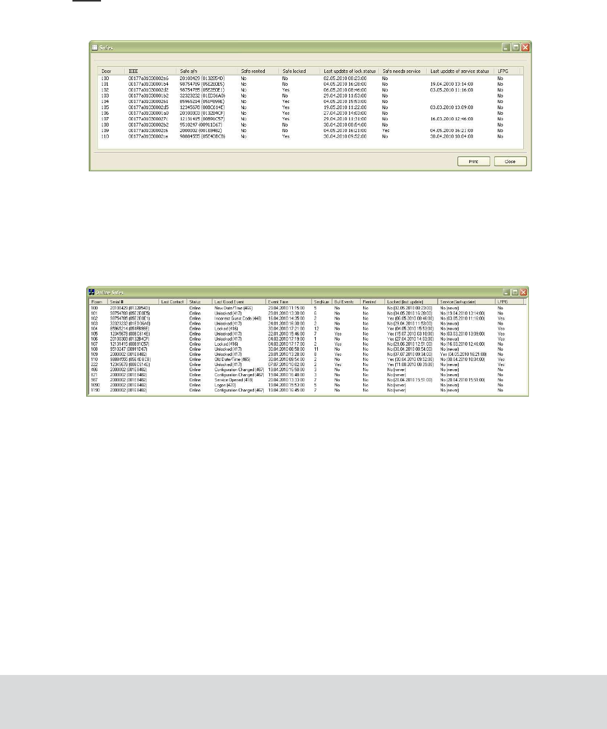
To install the option:
1. When you have got your option code, go to Tools/Option code.
2. Enter the option code and click Apply.
October 11, 2011 Page 14 of 22 66 3081 018-4
4.1.2 Settings at Tools/Options/Online/Safes
When the steps in section 4.1.1 have been performed, settings for the safes can be made in VISIONLINE.
1. Launch the VISIONLINE software and log on with user name and password.
2. Go to Tools/Options/Online/Safes.
3. If there should be an extra cost for the guest if a safe is used, “Enabled” (default) should be
marked. If there is no extra cost, “Enabled (no renting)” should be marked.
Note: If “Enabled” is chosen, the check box ‘Rent safe’ must be marked in the guest card
dialog before issuing the guest card; see section 4.7 Renting a safe for details. If cards are
encoded via PMS Plus and ‘Enabled’ is chosen, the RS field is used; see Specification for
PMS Plus Protocol (DP-060) for details.
4. If ‘Get info from safe at check-in’ is marked, an event about the status of the safe
(locked/unlocked) will be sent at guest check-in.
Note: The status of the safe is explicitly checked at check-in/check-out. If the check box
‘Get info from safe at check-in’ is not marked, the last known status is used. This may
cause unnecessary triggering of The safe is LFPG (locked from previos guest) alarms.
5. If the check box ‘Get info from safe at check-out’ is marked, an event about the status of
the safe (locked/unlocked) will be sent at guest check-out. See note in step 4.
6. If ‘Notify guest at check-out if safe is locked’ is marked, the guest will at check-out be
alerted by SMS or e-mail that the safe is still locked. The SMS/e-mail alert comes directly
at check-out, but the guest has some time (the Grace time entered in this dialog; default is
30 minutes, the valid range is 30-1440 minutes) to go back to the room and pick up the
belongings in the safe.
Note: The function ‘Notify guest at check-out if safe is locked’ requires that information about
the guest’s cell phone number and/or e-mail address has been given from PMS at check-in.
7. Click OK.
October 11, 2011 Page 15 of 22 66 3081 018-4
4.1 Safes list in VISIONLINE
If an RF-Online safe has been successfully installed and connected to the ZigBee network,
it should automatically appear in the Safes list in VISIONLINE.
Note: There is also a safes list in SysMon; see section 4.3.
1. Double click on Safes under the Lists tab in the navigation window.
4.3 Safes list in SysMon
The safes are also shown in a SysMon list, with some extra information in addition to the safes list
in VISIONLINE.
1. Launch SysMon and log on with the same user name and password as for VISIONLINE.
2. In the SysMon menu View, select Safes; the Online Safes window is shown.

October 11, 2011 Page 16 of 22 66 3081 018-4
4.4 Events
All operations of the safe are logged in the safe memory and sent as events to VISIONLINE.
Below is a list of the events available in VISIONLINE:
Event Description
Auto Relock Error The Auto Relock attempt was unsuccessful.
Clear Memory Deletes the audit trail.
Cold Start
The microprocessor of the safe was restarted. It happens when safe looses power
and gets it back again. Cold start does not delete anything from the safe memory.
Configuration Changed The safe configuration was changed.
Decoded The safe has been decoded.
Door Time-out
The locking bolt/latch hit the frame during locking. After 2-3 seconds it
automatically retracted.
Five Incorrect Codes The user has entered five different incorrect codes, which sets the safe in
countdown or service mode.
Incorrect Guest Code An incorrect code has been entered by the user. The incorrect code is recorded and
shown in the safe log.
Incorrect Service Code An incorrect service code has been entered.
Locked Safe locking by user code, card, or fingerprint depending on safe model.
Logoff
A logoff with a service unit has taken place. The User ID will be the same as for
‘logon’ (see above).
Logon
A logon with a service unit has taken place. The concerned user ID is stored in the
safe memory.
Low Battery
Mechanically Opened The locking latch was moved mechanically without the safe running the motor.
New Date/Time Internal safe clock was changed; this was the new date and time.
Old Date/Time Internal safe clock was changed; this was the old date and time.
‘Ser’ in display
The safe is unoperational and in “service mode”. Technical staff must service open
the safe.
Service Code Changed Service code of the safe has been changed.
Service Countdown Five incorrect service codes have been entered, which sets the safe in countdown
or service mode.
Service Opened The safe has been successfully service opened.
Service Open Error Service opening failed because the safe did not manage to move the locking
bolt/latch to open position.
Tamper Activated The tamper switch has been activated.
Time-out
The safe was not locked within 3 seconds after the code was entered or the
card/fingerprint was swept.
Unlocked
Normal unlocking of the safe by code, card, or fingerprint depending on
safe model.
October 11, 2011 Page 17 of 22 66 3081 018-4
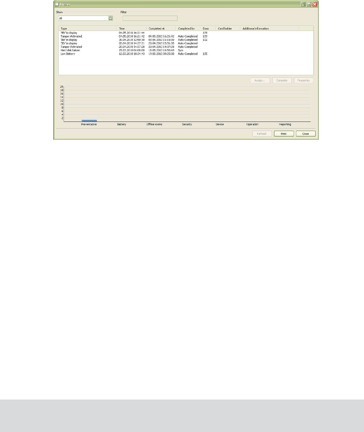
4.5 Alarms
Some of the events in section 4.4 will appear as alarms in the Alarms dialog of VISIONLINE.
1. Double click on Alarms under the Lists tab in the navigation window.
The following alarms can be received from the safe:
• Low Battery
•
Mechanically Opened
• Tamper Activated
• Clear Memory
• Auto Relock Error
• ‘Ser’ in display
October 11, 2011 Page 18 of 22 66 3081 018-4
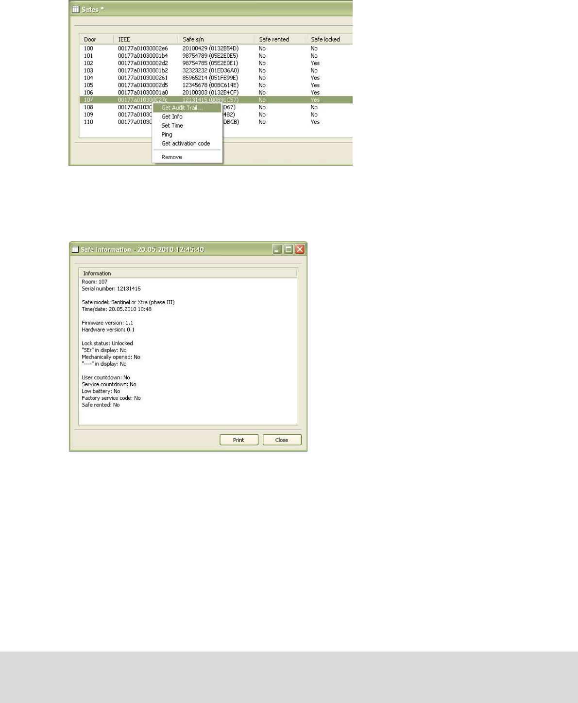
4.6 Commands for safes
In the Safes list of VISIONLINE, some commands are available in the right-click menu. The
commands are described in more detail in sections 4.6.1-4.6.5.
4.6.1 Get info
This function displays all available information about the safe.
October 11, 2011 Page 19 of 22 66 3081 018-4
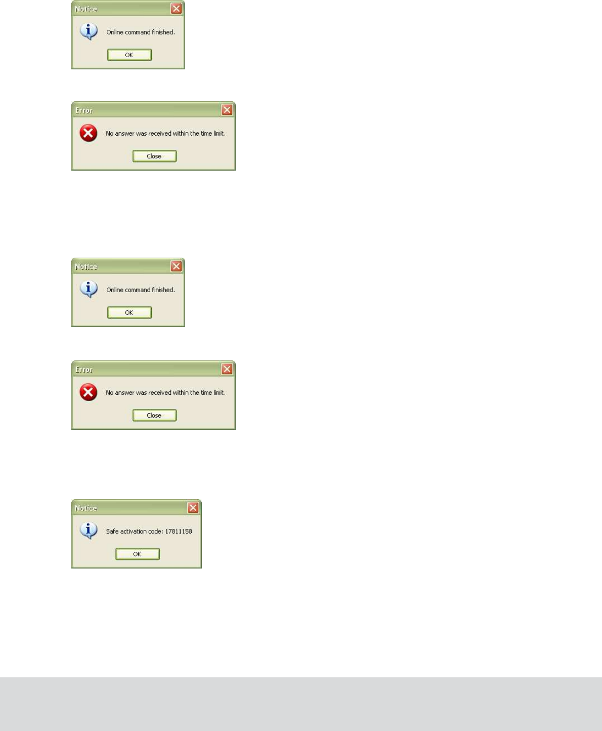
4.6.2 Set time
This command sets date and time to the current system values. If the operation has been successful,
the following message box will be displayed:
If the operation fails, the following message box will be displayed:
4.6.3 Ping
This feature tells the operator whether the safe is online or not. If the ping is successful, the following
message box will be displayed:
If the operation fails, the following message box will be displayed:
4.6.4 Get activation code
This command will display the activation code for a rented safe.
4.6.5 Remove
This command will remove the chosen safe from the Safes list in VISIONLINE.
October 11, 2011 Page 20 of 22 66 3081 018-4
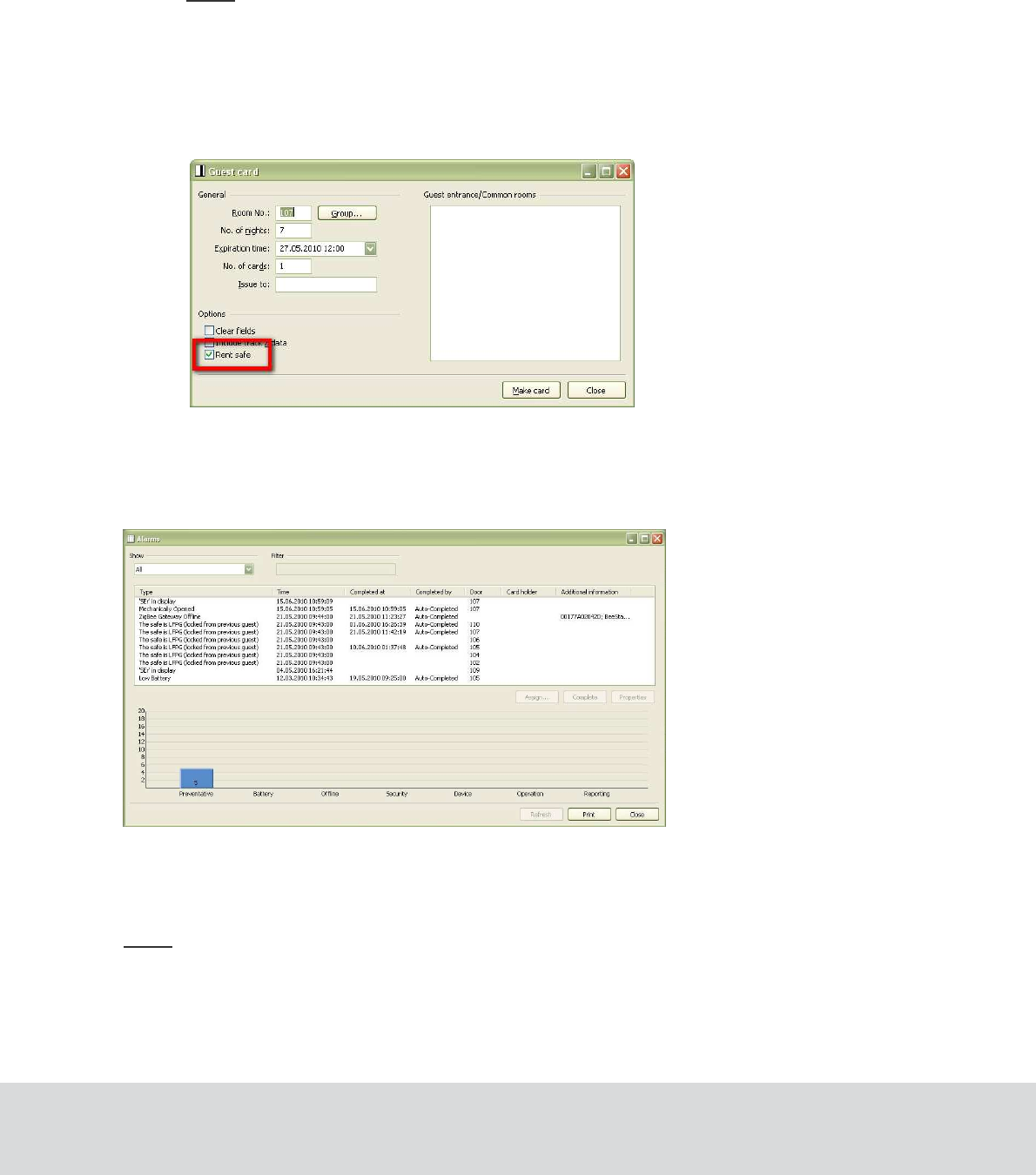
4.7 Renting a safe
If there is an extra cost for the guest to use the safe (requires that “Enabled” has been chosen at
Tools/Options/Online/Safes; see section 4.1.2 for details), the following actions must be taken:
•
The safe must be in CodeAct mode, which is set during production or by SafeLink when the
safe is commissioned. An activation code will be sent wireless to the safe, so the safe is ready
for usage when the guest arrives to the room.
Note: If the online network is temporarily shut down, the activation code must be printed
manually and the guest must manually activate the safe before first use.
•
The check box ‘Rent safe’ in the guest card dialog of VISIONLINE must be marked before
the guest card is issued:
1. Double click on Guest (or Guest advanced if that is applicable) under the Cards tab of
the navigation window.
4.7.1 At check-out
During guest check-out, the Alarms
dialog will if applicable show the alarm The safe is LFPG (locked from
previous guest).
If ‘Notify guest at check-out if safe is locked’ has been marked according to section 4.1.2, the guest will at
check-out be alerted by SMS or e-mail that the safe is still locked. The Safes list of VISIONLINE also has
a column ‘Safe locked’.
Note: The LFPG alarm is independent of whether ‘Notify guest at check-out if safe is locked’ has been
selected or not.
October 11, 2011 Page 21 of 22 66 3081 018-4
5 Troubleshooting
Problem Solution
The safe cannot connect to the ZigBee
network and does not appear in the
ZigBee Network window in SysMon.
• Move the router closer to the safe to gain the best
possible link quality.
• Repeat the discovery procedure.
The safe appears in the ZigBee
Network window, but the room number
is not shown.
• Check with SafeLink if the safe is properly
commissioned.
Note: The safe cannot have room number 0 (zero).
After the discovery procedure, the safe
“took over” the number from another safe
shown in the ZigBee Network window
of SysMon.
• Check with SafeLink if the safe is properly
commissioned.
• Perform the Get Info command from the Safes
list of VISIONLINE, to be sure that the safe has
the proper room number stored in its memory.
• Check the IEEE addresses of the endnodes in
both safes.
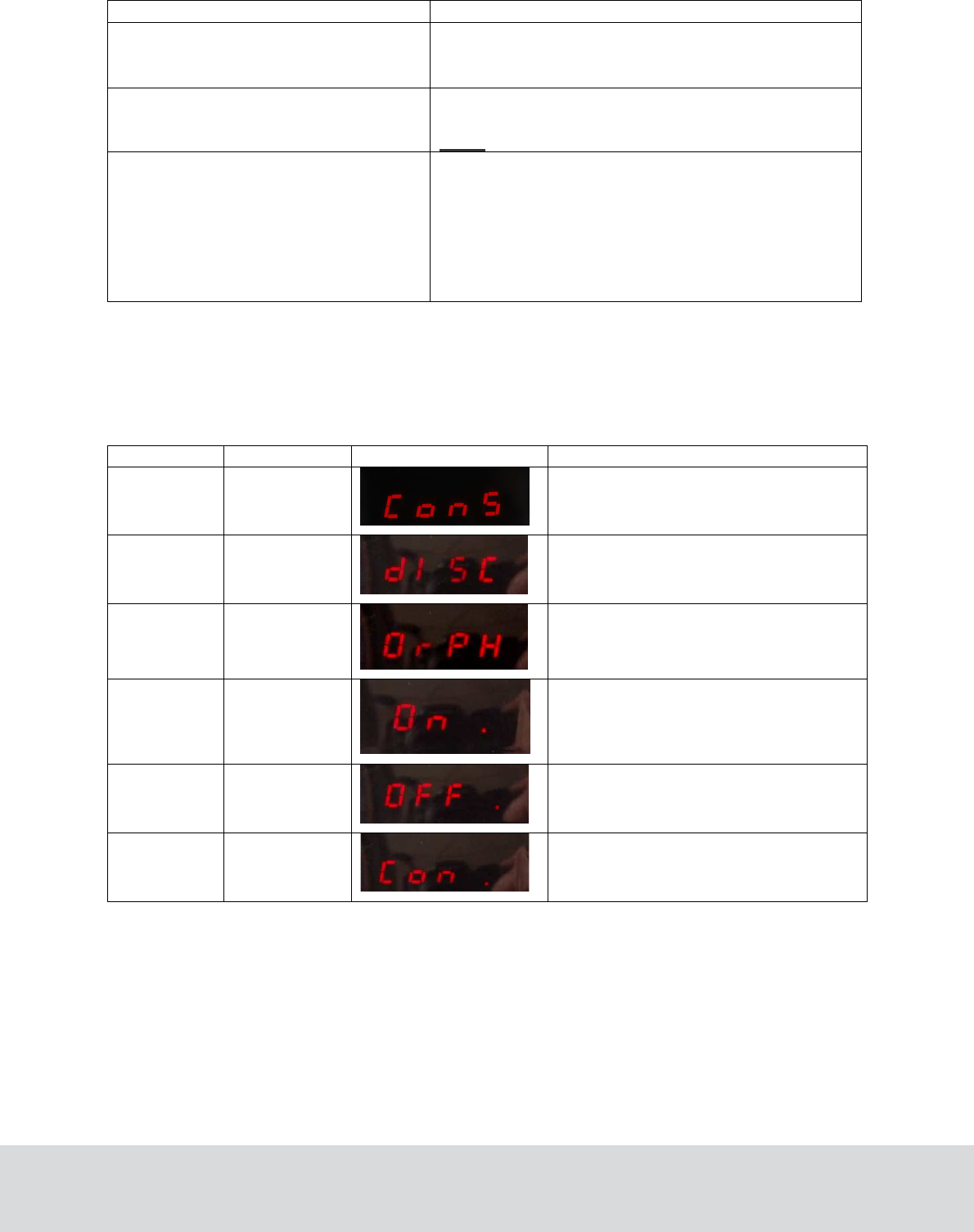
6 Service commands
The table below contains a list of service commands and safe status modes which can be shown on the
safe display.
Action Safe display Display picture Description
Reset + 2 ConS
Sets the safe in construction mode
Reset + 3 diSC
Sets the safe in discovery mode
Reset + 4 OrPH
Sets the safe in orphan join mode
Reset + 5 On .
Safe status:
Safe connected to ZigBee network
Reset + 5 OFF.
Safe status:
Safe disconnected from the network
Reset + 5 Con.
Safe status:
Construction mode
To execute a service command:
1. Press and hold the Reset and the applicable one of the 2, 3 or 4 buttons down.
To display the safe status mode:
1. Press and hold the Reset
and 5 buttons down.

October 11, 2011 Page 22 of 22 66 3081 018-4
Revision history
Date Change By
30.04.2010 First draft RKo
27.08.2010 First release KG
27.01.2011 Revision 1 (FCC/IC approval added;
superfluous article numbers removed) KG
08.09.2011 Revision 2 (FCC/IC number added) KG
11.10.2011 Revision 3 (additional FCC/IC text added; article number
for endnode changed to the VingCard number; irrelevant
article numbers removed; new logotypes and other layout changes)
KG
20.10.2011 Revision 4 (Industry Canada statements in English and French
added to the FCC/IC text) KG
October 11, 2011 Page 23 of 22 66 3081 018-4