ASSALOY Identification Technologies RDHC-0502N0-0X Inductive Tad Reader Module User Manual HF Mifare Easy V1 0 04
ASSA ABLOY Identification Technologies GmbH Inductive Tad Reader Module HF Mifare Easy V1 0 04
UserManual.wiki
>
ASSALOY Identification Technologies
>
RDHC 0502N0 0X User Manual
Users Manual
Navigation menu
Upload a User Manual
Namespaces
Wiki Guide
HTML
PDF
Info
Views
User Manual
Discussion / Help
Navigation

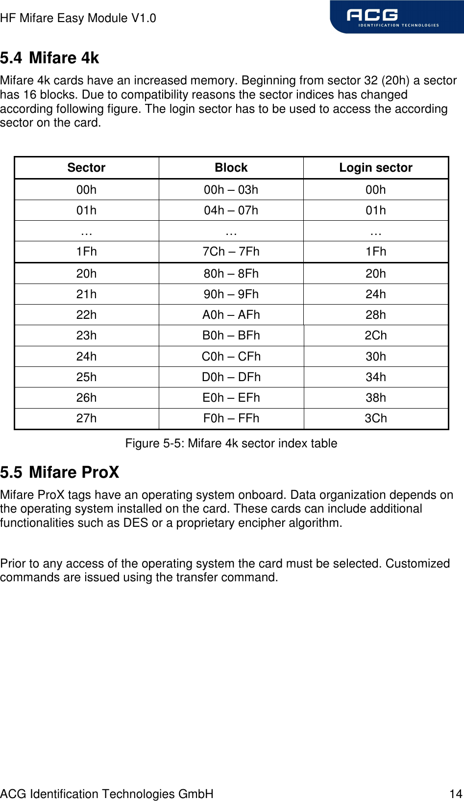
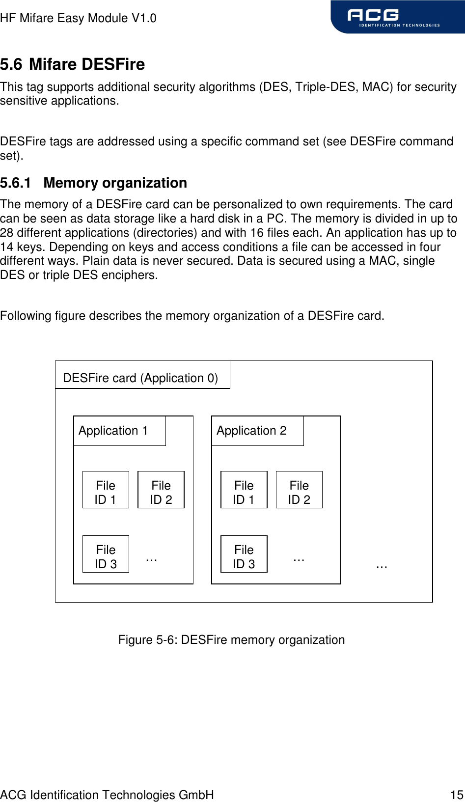
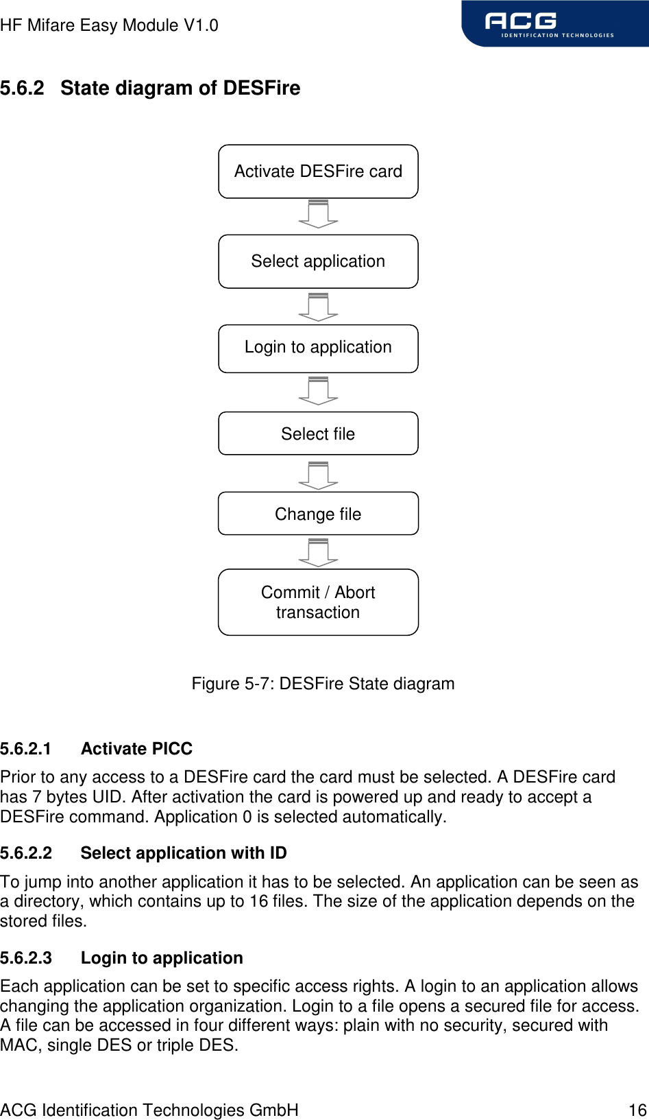
![HF Mifare Easy Module V1.0 ACG Identification Technologies GmbH 17 5.6.2.4 Select file with ID Prior to any access to a file a file must be selected 5.6.2.5 Change file A selected file can be changed according its access rights. If a file is secured a login is needed before. 5.6.2.6 Commit/ Abort transaction Value files, backup files, linear record files and cyclic record files only adapt its value after the commit transaction command. Several files can be changed within an application at the same time. The abort transactions command annulates all changes within an application. Power loss will cancel all modifications too. For more details about the application settings and access rights refer to [2].](https://usermanual.wiki/ASSALOY-Identification-Technologies/RDHC-0502N0-0X/User-Guide-702094-Page-18.png)
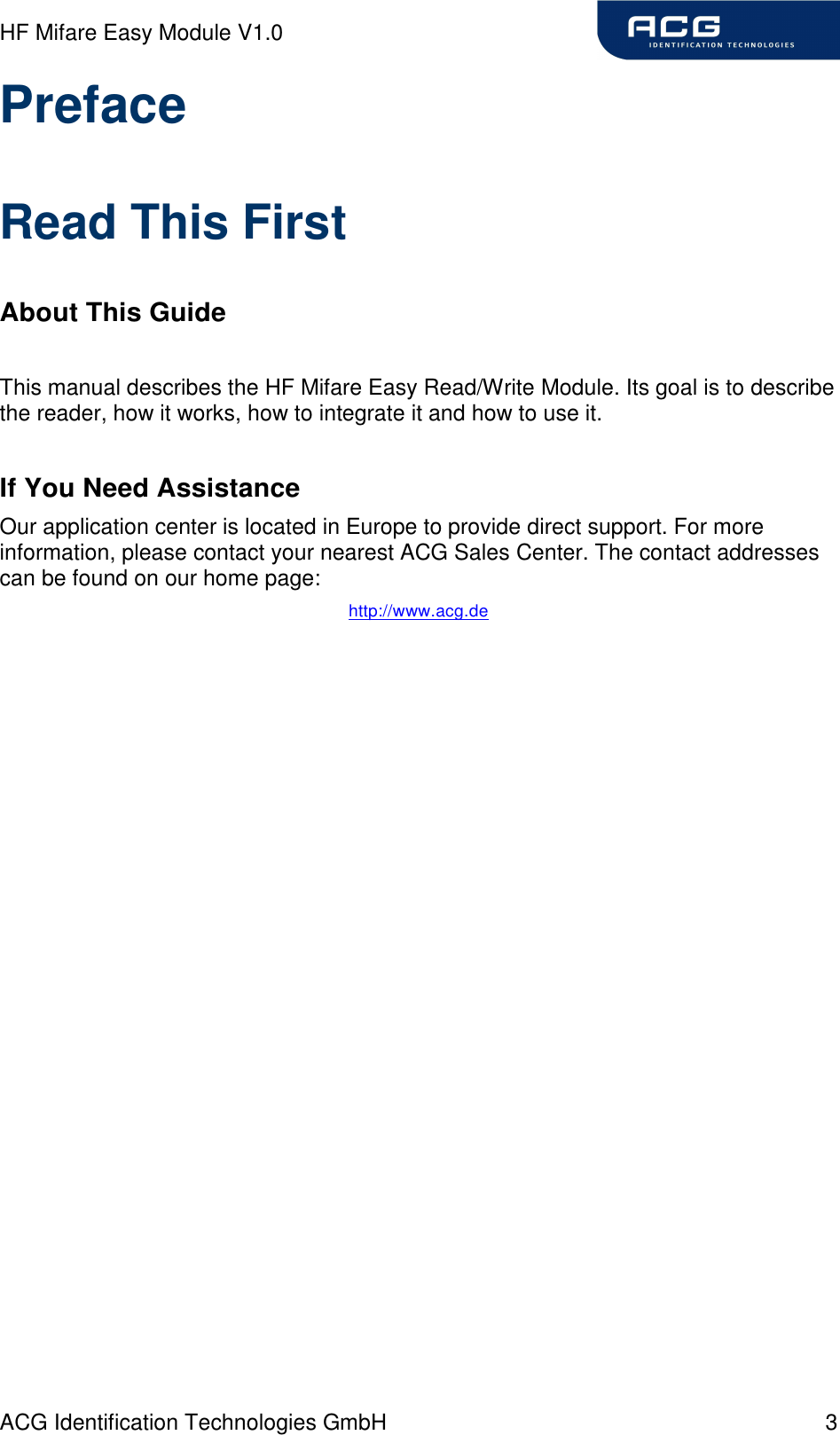
![HF Mifare Easy Module V1.0 ACG Identification Technologies GmbH 39 7.4.3.5.1 Time slotted answer In party line mode more than one reader can be used simultaneously. The time slotted answer allows separating all connected devices. The station ID is used to determine the correct time slot. The reader supports up to 254 unique time slots. Following formula calculates the needed time of one time slot. Only one baud rate on the same party line is supported. 6*10][0BaudratesT = Figure 7-10: Time slot formula Following figure shows the timing diagram of time slotted answers. timeslot 0 1 2 3 4 5 … 252 253 254 T0 T1 T2 T3 T4 T5 T253 T254 T255 HOST 'g' → reader (01) ← 01 reader (03) ← 03 reader (04) ← 04 reader (254) ← 254 Figure 7-11: Timing diagram of time slotted answers](https://usermanual.wiki/ASSALOY-Identification-Technologies/RDHC-0502N0-0X/User-Guide-702094-Page-40.png)
![HF Mifare Easy Module V1.0 ACG Identification Technologies GmbH 61 9 References [1] ISO/IEC 14443 Part 1-4, Identification Cards – Contactless integrated circuit(s) cards – Proximity cards [2] DESFire Documentation, Philips, http://www.semiconductors.philips.com [3] ACG Antenna Design Guide [4] Philips; Application Note, Mifare® & I-Code, Micore Reader IC family Directly Matched Antenna Design](https://usermanual.wiki/ASSALOY-Identification-Technologies/RDHC-0502N0-0X/User-Guide-702094-Page-62.png)
![HF Mifare Easy Module V1.0 ACG Identification Technologies GmbH 62 10 Appendix A: Antenna According to antenna design, please refer to Philips Application Note (Mifare ® & I-Code, Mifare Reader IC family Directly Matched Antenna Design [4]) or to the ACG Antenna Design Guide [3].](https://usermanual.wiki/ASSALOY-Identification-Technologies/RDHC-0502N0-0X/User-Guide-702094-Page-63.png)
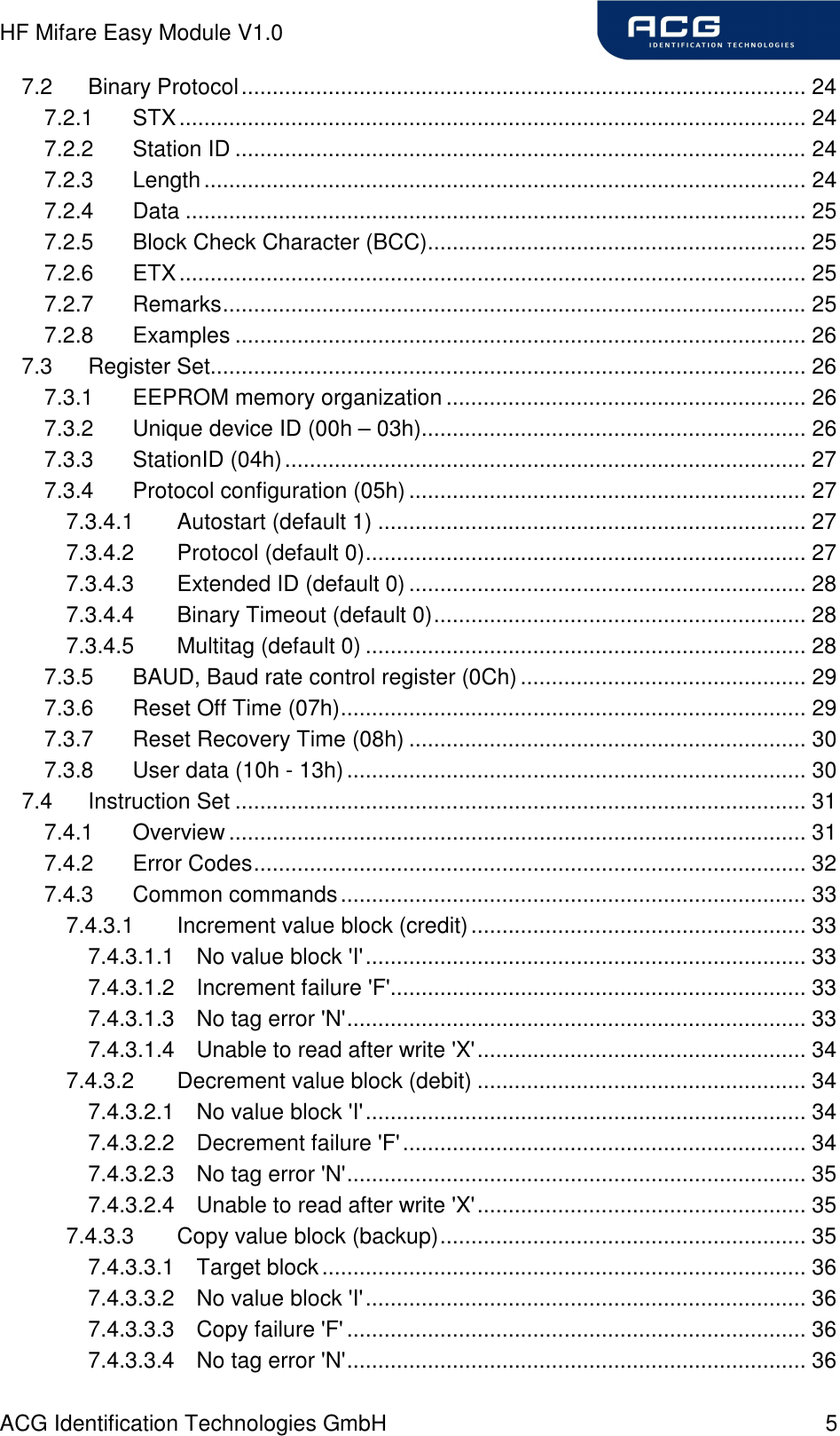
![HF Mifare Easy Module V1.0 ACG Identification Technologies GmbH 67 13 Appendix D: Timings tCMD tEXEC tRES PC: Request → Reader: ← Response Command tEXEC [ms] Comments Common commands cont. read 7 + Reset Off and Recovery Time multiselect 10 + Reset Off and Recovery Time multiselect (no tag) 35.4 + Reset Off and Recovery Time antenna on 0.5 antenna off 0.6 port read 0.3 port write 0.3 read block 4.1 write block 11.6 reset 107 select 8.8 + Reset Off and Recovery Time select (no tag) 35.4 + Reset Off and Recovery Time increment value block 15.1 decrement value block 15.1 copy value block 15 read value block 4 write value block 15.5 Power conditions Power on 145 excluded raising time of power supply Enable on 114 Figure 13-1: Timings All timing data is advisory application information and does not form part of the specification. It may change in further firmware releases. Please note also that all in the above table specified values depend on the used tag.](https://usermanual.wiki/ASSALOY-Identification-Technologies/RDHC-0502N0-0X/User-Guide-702094-Page-68.png)