ASSALOY Identification Technologies RDHC-0502N0-0X Inductive Tad Reader Module User Manual HF Mifare Easy V1 0 04
ASSA ABLOY Identification Technologies GmbH Inductive Tad Reader Module HF Mifare Easy V1 0 04
Users Manual

Document Nr.: QSI-040902-OM-1-a-UserManual Dual ISO Module, V2.0
ACG Identification Technologies GmbH
Am Klingenweg 6A
65396 Walluf
Germany
Phone +49 (0) 6123 791 0
Fax +49 (0) 6123 791 199
www.acg.de
rfid@acg.de
ACG HF Mifare Easy Module
Document No.: 1503-USM-01-0-01
Firmware: Version 1.0
User Manual

HF Mifare Easy Module V1.0
ACG Identification Technologies GmbH 1
Edition One - April 2005
ACG Identification Technologies GmbH (ACG) reserves the right to make changes to
its products or services or to discontinue any product or service at any time without
notice. ACG provides customer assistance in various technical areas, but does not
have full access to data concerning the use and applications of customer's products.
Therefore, ACG assumes no liability and is not responsible for customer applications
or product or software design or performance relating to systems or applications
incorporating ACG products. In addition, ACG assumes no liability and is not
responsible for infringement of patents and/or any other intellectual or industrial
property rights of third parties, which may result from assistance provided by ACG.
ACG products are not designed, intended, authorized or warranted to be suitable for
life support applications or any other life critical applications that could involve poten-
tial risk of death, personal injury or severe property or environmental damage.
With the edition of this document, all previous editions become void. Indications
made in this manual may be changed without previous notice.
Composition of the information in this manual has been done to the best of our
knowledge. ACG does not guarantee the correctness and completeness of the
details given in this manual and may not be held liable for damages ensuing from
incorrect or incomplete information. Since, despite all our efforts, errors may not be
completely avoided, we are always grateful for your useful tips.
The installation instructions given in this manual are based on advantageous
boundary conditions. ACG does not give any guarantee promise for perfect function
in cross environments.
The ACG logo is a registered trademark of ACG Identification Technologies GmbH.
Copyright © 2005 ACG Identification Technologies GmbH (ACG)
This document may be downloaded onto a computer, stored and duplicated as nec-
essary to support the use of the related ACG products. Any other type of duplication,
circulation or storage on data carriers in any manner not authorized by ACG
represents a violation of the applicable copyright laws and shall be prosecuted.

HF Mifare Easy Module V1.0
ACG Identification Technologies GmbH 2
Safety Instructions / Warning - Read before start-up!
• The device may only be used for the intended purpose designed by for the
manufacturer. The operation manual should be conveniently kept available at
all times for each user.
• Unauthorized changes and the use of spare parts and additional devices that
have not been sold or recommended by the manufacturer may cause fire,
electric shocks or injuries. Such unauthorized measures shall exclude any
liability by the manufacturer.
• The liability-prescriptions of the manufacturer in the issue valid at the time of
purchase are valid for the device. The manufacturer shall not be held legally
responsible for inaccuracies, errors, or omissions in the manual or
automatically set parameters for a device or for an incorrect application of a
device.
• Repairs may be executed by the manufacturer only.
• Only qualified personnel should carry out installation, operation, and
maintenance procedures.
• Use of the device and its installation must be in accordance with national legal
requirements and local electrical codes.
• When working on devices the valid safety regulations must be observed.

HF Mifare Easy Module V1.0
ACG Identification Technologies GmbH 3
Preface
Read This First
About This Guide
This manual describes the HF Mifare Easy Read/Write Module. Its goal is to describe
the reader, how it works, how to integrate it and how to use it.
If You Need Assistance
Our application center is located in Europe to provide direct support. For more
information, please contact your nearest ACG Sales Center. The contact addresses
can be found on our home page:
http://www.acg.de

HF Mifare Easy Module V1.0
ACG Identification Technologies GmbH 4
Table of contents
1
Scope...............................................................................................8
2
Extended Documentation...............................................................8
3
Definitions and abbreviations........................................................8
3.1 Definitions .................................................................................................... 8
3.1.1 Anticollision loop ................................................................................... 8
3.1.2 Hex notation.......................................................................................... 8
3.1.3 ASCII notation....................................................................................... 8
3.2 Abbreviations................................................................................................ 9
4
Supported tags..............................................................................10
5
The Mifare transponder family.....................................................11
5.1 State Diagram ............................................................................................ 11
5.2 Mifare Standard.......................................................................................... 12
5.2.1 Definitions ........................................................................................... 12
5.2.2 Sector 0 / Block 0................................................................................ 13
5.2.3 Block 3, 7, 11, 15, …........................................................................... 13
5.3 Mifare Ultralight .......................................................................................... 13
5.4 Mifare 4k .................................................................................................... 14
5.5 Mifare ProX ................................................................................................ 14
5.6 Mifare DESFire........................................................................................... 15
5.6.1 Memory organization........................................................................... 15
5.6.2 State diagram of DESFire ................................................................... 16
5.6.2.1 Activate PICC............................................................................... 16
5.6.2.2 Select application with ID............................................................. 16
5.6.2.3 Login to application...................................................................... 16
5.6.2.4 Select file with ID ......................................................................... 17
5.6.2.5 Change file................................................................................... 17
5.6.2.6 Commit/ Abort transaction............................................................ 17
6
Hardware .......................................................................................18
6.1 Pin out of OEM Module (Top View)............................................................ 18
6.1.1 Pin out................................................................................................. 19
6.1.2 Electrical characteristics of PINs......................................................... 20
6.1.3 External Connections.......................................................................... 21
6.1.3.1 Power Supply............................................................................... 21
6.1.3.2 Antenna........................................................................................ 22
6.1.3.3 Serial Interface............................................................................. 22
6.1.3.4 Function Control LEDs................................................................. 23
7
Software.........................................................................................24
7.1 ASCII Protocol............................................................................................ 24

HF Mifare Easy Module V1.0
ACG Identification Technologies GmbH 5
7.2 Binary Protocol........................................................................................... 24
7.2.1 STX..................................................................................................... 24
7.2.2 Station ID ............................................................................................ 24
7.2.3 Length................................................................................................. 24
7.2.4 Data .................................................................................................... 25
7.2.5 Block Check Character (BCC)............................................................. 25
7.2.6 ETX..................................................................................................... 25
7.2.7 Remarks.............................................................................................. 25
7.2.8 Examples ............................................................................................ 26
7.3 Register Set................................................................................................ 26
7.3.1 EEPROM memory organization .......................................................... 26
7.3.2 Unique device ID (00h – 03h).............................................................. 26
7.3.3 StationID (04h).................................................................................... 27
7.3.4 Protocol configuration (05h) ................................................................ 27
7.3.4.1 Autostart (default 1) ..................................................................... 27
7.3.4.2 Protocol (default 0)....................................................................... 27
7.3.4.3 Extended ID (default 0)................................................................ 28
7.3.4.4 Binary Timeout (default 0)............................................................ 28
7.3.4.5 Multitag (default 0) ....................................................................... 28
7.3.5 BAUD, Baud rate control register (0Ch).............................................. 29
7.3.6 Reset Off Time (07h)........................................................................... 29
7.3.7 Reset Recovery Time (08h) ................................................................ 30
7.3.8 User data (10h - 13h).......................................................................... 30
7.4 Instruction Set ............................................................................................ 31
7.4.1 Overview ............................................................................................. 31
7.4.2 Error Codes......................................................................................... 32
7.4.3 Common commands........................................................................... 33
7.4.3.1 Increment value block (credit)...................................................... 33
7.4.3.1.1 No value block 'I'....................................................................... 33
7.4.3.1.2 Increment failure 'F'................................................................... 33
7.4.3.1.3 No tag error 'N'.......................................................................... 33
7.4.3.1.4 Unable to read after write 'X'..................................................... 34
7.4.3.2 Decrement value block (debit) ..................................................... 34
7.4.3.2.1 No value block 'I'....................................................................... 34
7.4.3.2.2 Decrement failure 'F'................................................................. 34
7.4.3.2.3 No tag error 'N'.......................................................................... 35
7.4.3.2.4 Unable to read after write 'X'..................................................... 35
7.4.3.3 Copy value block (backup)........................................................... 35
7.4.3.3.1 Target block.............................................................................. 36
7.4.3.3.2 No value block 'I'....................................................................... 36
7.4.3.3.3 Copy failure 'F' .......................................................................... 36
7.4.3.3.4 No tag error 'N'.......................................................................... 36

HF Mifare Easy Module V1.0
ACG Identification Technologies GmbH 6
7.4.3.3.5 Unable to read after write 'X'..................................................... 36
7.4.3.4 Continuous Read ......................................................................... 37
7.4.3.4.1 Multitag continuous read mode................................................. 37
7.4.3.4.2 Auto start .................................................................................. 37
7.4.3.4.3 Binary mode.............................................................................. 37
7.4.3.4.4 Simple access control applications........................................... 38
7.4.3.4.5 Extended ID.............................................................................. 38
7.4.3.5 Get Station ID .............................................................................. 38
7.4.3.5.1 Time slotted answer.................................................................. 39
7.4.3.6 Login (authenticate tag) ............................................................... 40
7.4.3.6.1 No tag error 'N'.......................................................................... 41
7.4.3.6.2 <CR> ........................................................................................ 41
7.4.3.6.3 Login with keydata from EEPROM ........................................... 42
7.4.3.6.4 Usage of key A, key B............................................................... 42
7.4.3.7 Multi Tag Selection / List.............................................................. 42
7.4.3.7.1 Multi tag list............................................................................... 43
7.4.3.7.2 Reading distance...................................................................... 43
7.4.3.7.3 Multi tag select.......................................................................... 43
7.4.3.7.4 Multi tag reset ........................................................................... 43
7.4.3.7.5 Maximum number of tags ......................................................... 43
7.4.3.8 Antenna power on/off................................................................... 44
7.4.3.8.1 Power off................................................................................... 44
7.4.3.8.2 Power on................................................................................... 44
7.4.3.8.3 Reset Timing............................................................................. 44
7.4.3.9 Read/Write user port.................................................................... 45
7.4.3.9.1 Read port.................................................................................. 45
7.4.3.9.2 Write port .................................................................................. 46
7.4.3.10 Read block................................................................................... 46
7.4.3.10.1 Read failure 'F'........................................................................ 47
7.4.3.10.2 No tag in field 'N'..................................................................... 47
7.4.3.10.3 Operation mode failure 'O' ...................................................... 47
7.4.3.11 Read reader EEPROM................................................................. 47
7.4.3.12 Read value block ......................................................................... 48
7.4.3.12.1 No value block 'I'..................................................................... 48
7.4.3.12.2 No tag error 'N'........................................................................ 48
7.4.3.12.3 General failure 'F'.................................................................... 48
7.4.3.13 Select........................................................................................... 49
7.4.3.13.1 Select a single tag................................................................... 49
7.4.3.13.2 Extended ID............................................................................ 49
7.4.3.13.3 Multiple tags............................................................................ 49
7.4.3.14 Get Version.................................................................................. 50
7.4.3.15 Write block ................................................................................... 51

HF Mifare Easy Module V1.0
ACG Identification Technologies GmbH 7
7.4.3.15.1 Write failure 'F'........................................................................ 51
7.4.3.15.2 No tag error 'N'........................................................................ 51
7.4.3.15.3 Operation mode failure 'O' ...................................................... 52
7.4.3.16 Write EEPROM............................................................................ 52
7.4.3.17 Write master key.......................................................................... 53
7.4.3.17.1 Writing master keys ................................................................ 53
7.4.3.17.2 Using master keys for authentication...................................... 53
7.4.3.18 Write value block.......................................................................... 54
7.4.3.18.1 Invalid value 'I' ........................................................................ 54
7.4.3.18.2 Write failure 'F'........................................................................ 54
7.4.3.18.3 No tag error 'N'........................................................................ 54
7.4.3.18.4 Writing values ......................................................................... 55
7.4.3.19 Reset............................................................................................ 55
7.4.3.19.1 Reset Timing........................................................................... 55
8
Frequently Asked Questions........................................................56
8.1 Getting Started........................................................................................... 56
8.2 How should the Mifare Easy Reader be personalized?.............................. 56
8.3 What type of Mifare
®
card should I use? .................................................... 57
8.4 How safe is Mifare
®
Standard for cashless payment?................................ 58
8.5 Mifare
®
Standard Sector Trailer and Access Conditions............................ 59
8.5.1 Examples ............................................................................................ 60
8.5.1.1 Ticketing Applications .................................................................. 60
8.5.1.2 Data Handling Applications.......................................................... 60
8.5.1.3 No Security, open configuration................................................... 60
8.6 Using a Mifare card .................................................................................... 60
9
References ....................................................................................61
10
Appendix A: Antenna.................................................................62
11
Appendix B: Compact P&P Module..........................................63
12
Appendix C: Short Range P&P Module....................................65
13
Appendix D: Timings .................................................................67
14
Appendix E: Release Notes.......................................................68
14.1 Version History........................................................................................... 68
14.1.1 Mifare 1.0............................................................................................ 68
14.2 Revision history.......................................................................................... 68
15
Appendix F: CE Declaration......................................................69
16
Appendix G: FCC Declaration...................................................70

HF Mifare Easy Module V1.0
ACG Identification Technologies GmbH 8
1 Scope
The MIFARE® Application Oriented Protocol is a reader Interface to communicate
with MIFARE® transponders. The major applications to be supported are:
• Access control, Identification: Reading the serial numbers of all cards in
the field.
• Data Storage: Performing encrypted read and write operations.
• Ticketing: Performing read, write, increment and decrement operations
in an encrypted environment.
• Multi applications: Performing read, write, increment and decrement
operations on various sectors of the MIFARE® Standard tags using
different encryption keys.
2 Extended Documentation
Please note that all confidential materials are not part of this documentation.
You can obtain an extended documentation containing that material after signing a
NDA.
3 Definitions and abbreviations
3.1 Definitions
3.1.1 Anticollision loop
Algorithm processed to identify and handle a dialogue between reader and one or
more tags in its antenna field.
3.1.2 Hex notation
A hexadecimal value is noted with a following h, i.e. A1h has the value A1
hexadecimal.
3.1.3 ASCII notation
ASCII characters are listed within apostrophes, i.e. ‘x’ means a single x.

HF Mifare Easy Module V1.0
ACG Identification Technologies GmbH 9
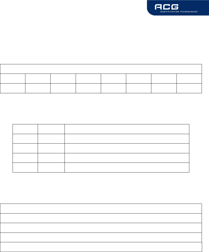
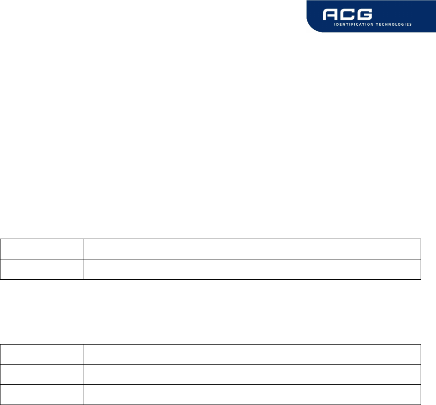
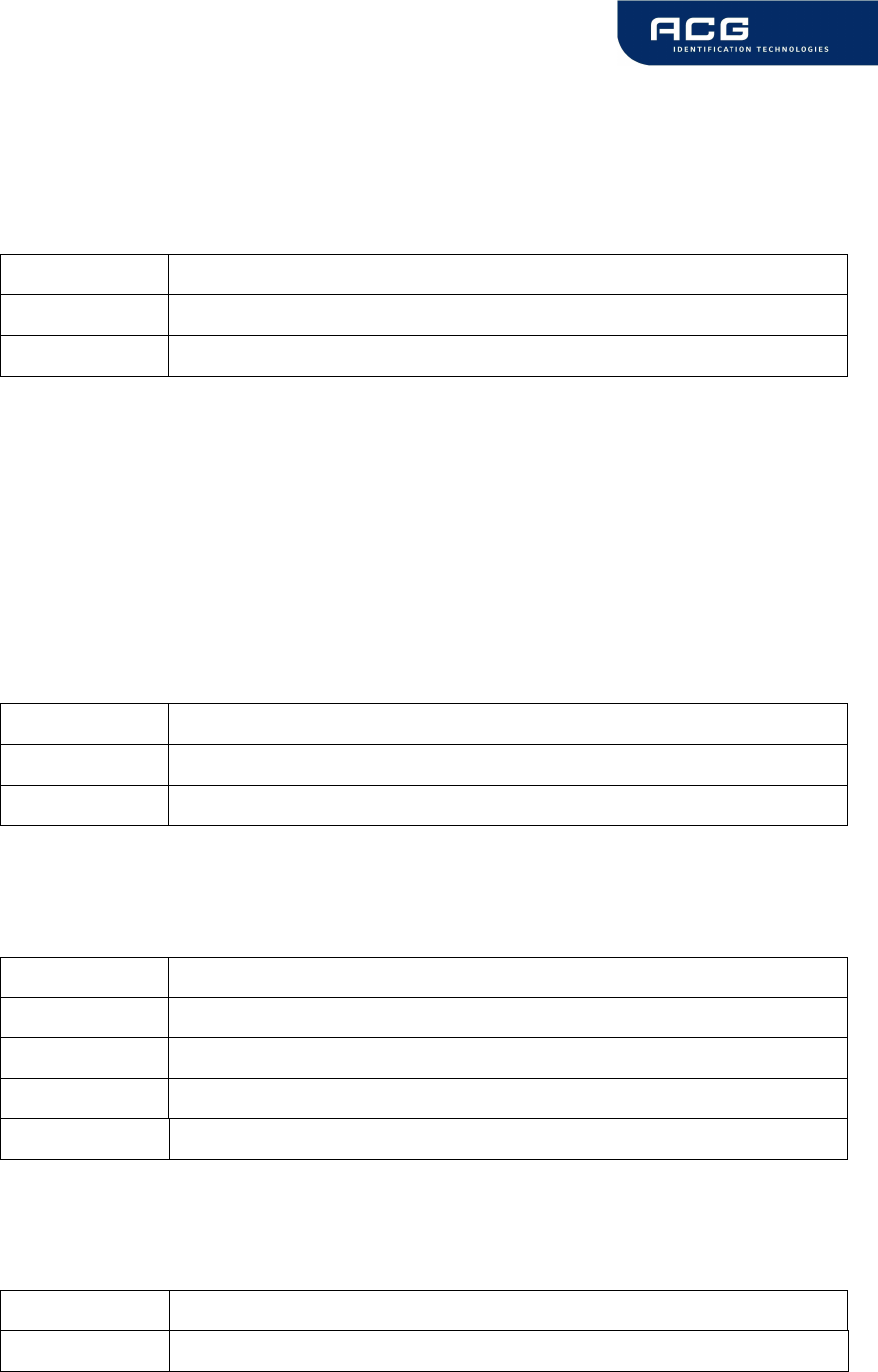
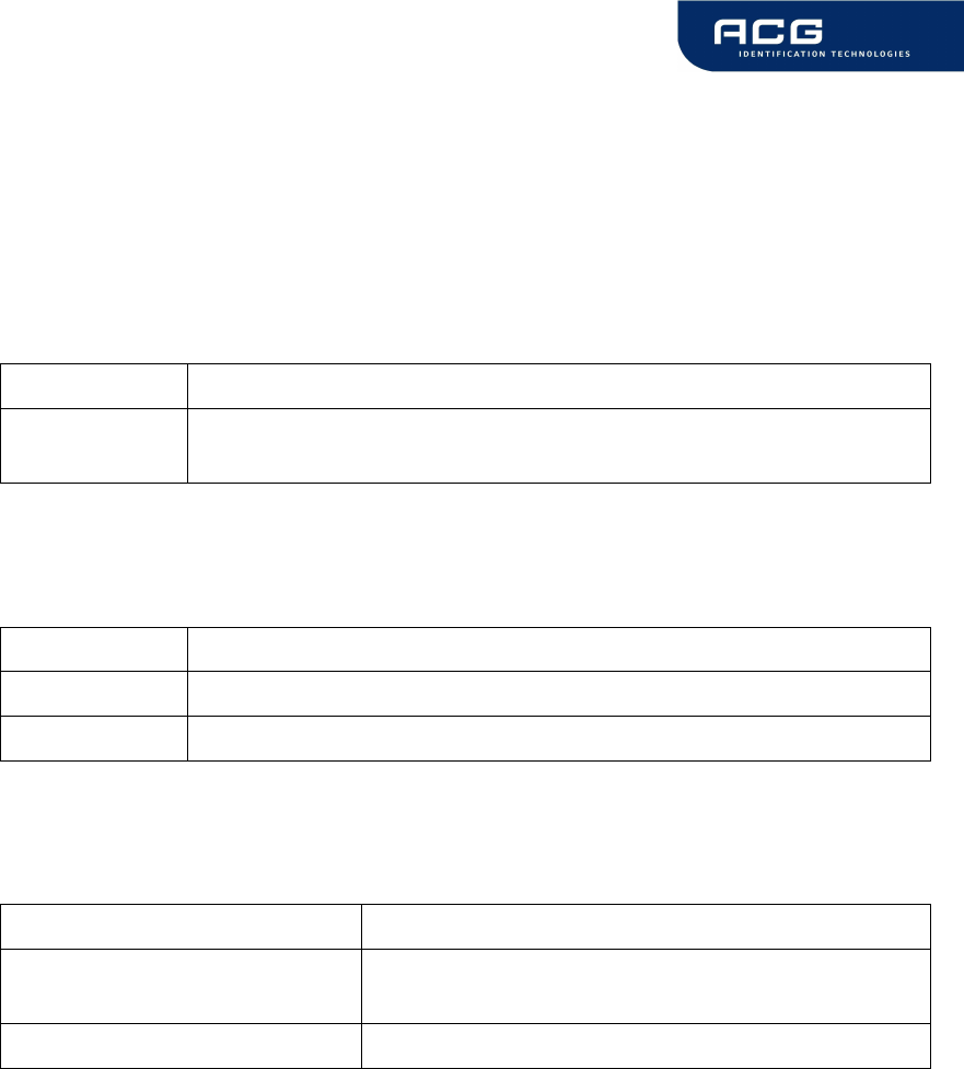
3.2 Abbreviations
Abbreviation Description
ASCII American Standard Code for Information Interchange
block For Mifare
®
Standard one block contains 16 bytes
EOF End of frame
hex / xxh value in Hexadecimal notation
LSB Least Significant Bit or Byte
MSB Most Significant Bit or Byte
PCON Protocol Configuration byte of the reader
REQA Request ISO Type A
RFU Reserved for Future Use
sector For Mifare
®
Standard one sector contains 4 blocks
SID Station ID
SN Serial Number of a tag
SOF Start of frame
value block 32 bit data block format. Used in ticketing application
<CR> Carriage return (0Dh)
<LF> Line feed (0Ah)
Figure 3-1: Abbreviations

HF Mifare Easy Module V1.0
ACG Identification Technologies GmbH 10
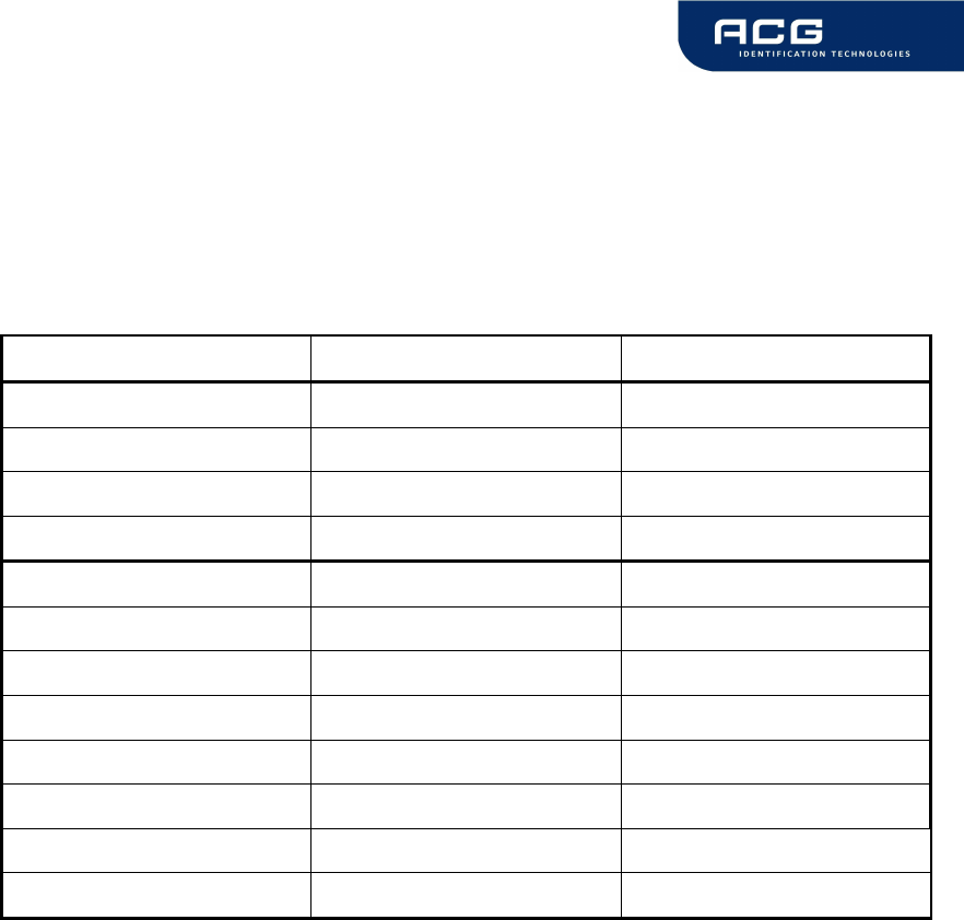
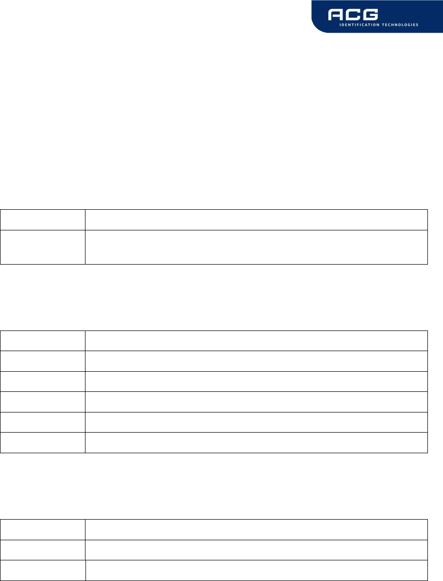
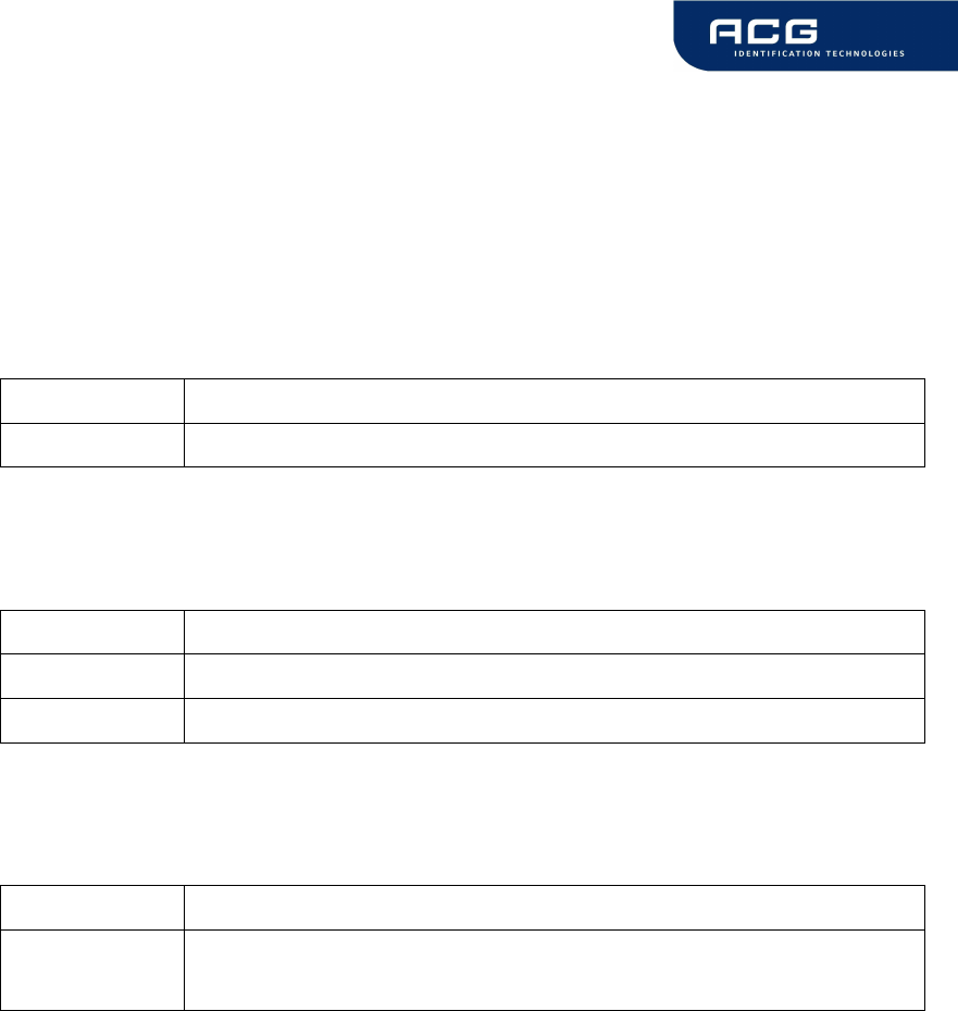
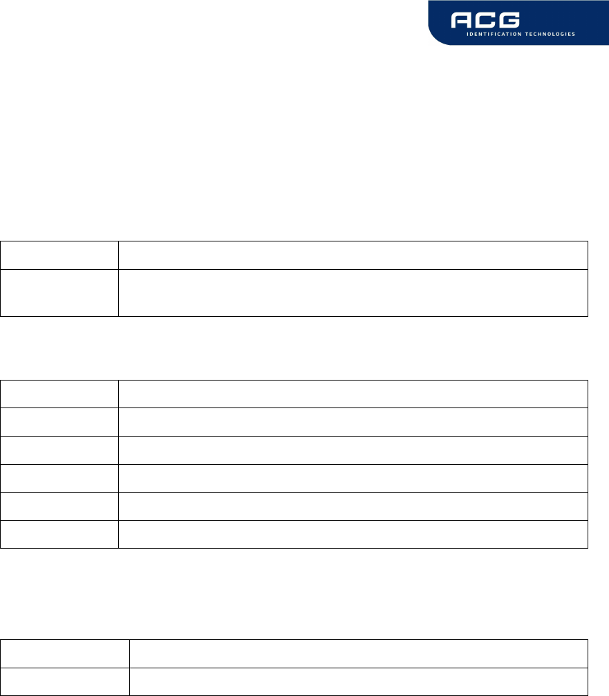
4 Supported tags
Comments
encryption not included
encryption not included
Transfer
command
√
√
√
√
√
√
√
√
√
Write
block
√
√
√
√
-
-
√
-
√
Read
bock
√
√
√
√
-
-
√
-
√
Serial
number
√
√
√
√
√
√
√
√
√
Manufacturer
Philips
Philips
Philips
Philips
Philips
Philips
Infineon
Infineon
Infineon
Mifare Standard
Mifare 4k
Mifare Ultralight
Mifare ProX
DESFire
Smart MX
SLE44R35S
SLE55R04/08/16
SLE66R35
Figure 4-1: Supported labels
HF Mifare Easy Module V1.0
ACG Identification Technologies GmbH 11
5 The Mifare transponder family
The Mifare transponder family consists of various 13.56 MHz transponders IC, all
according to ISO 14443.
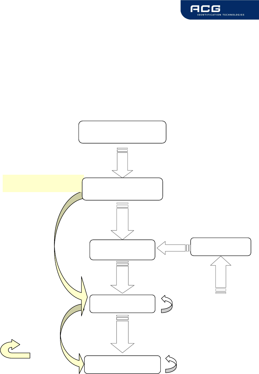
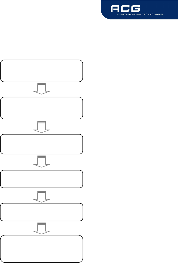
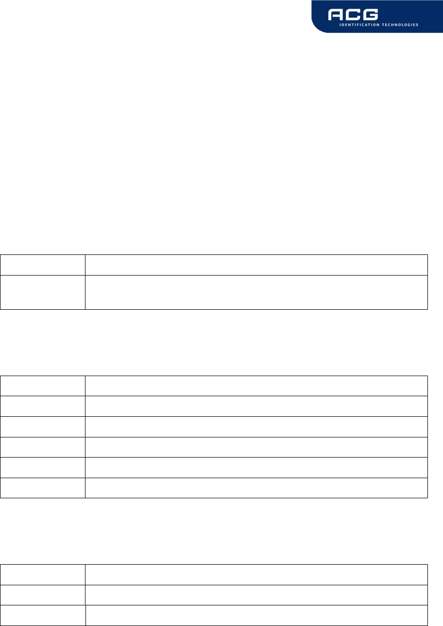
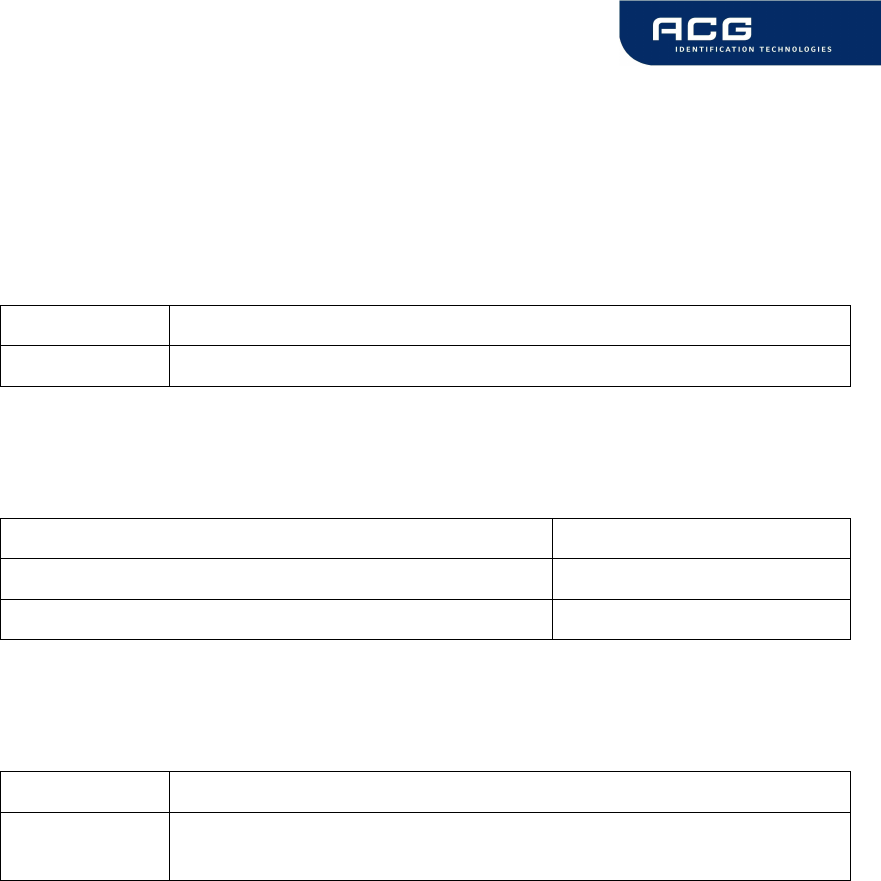
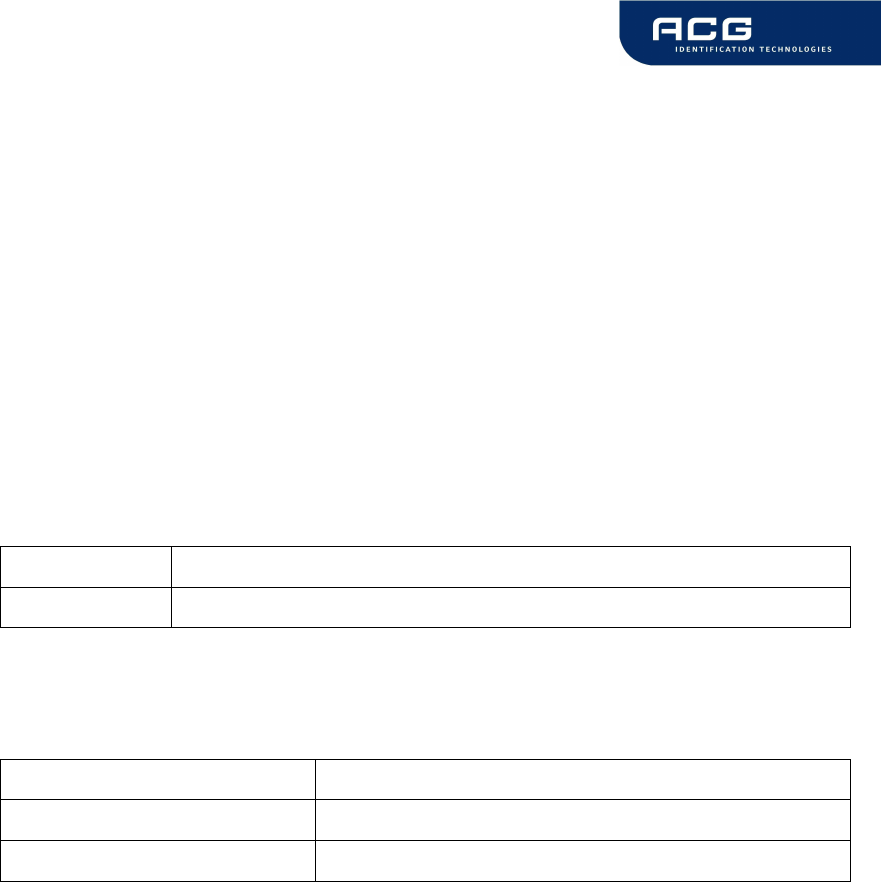
5.1 State Diagram
All Mifare cards use following state diagram.
Figure 5-1: State diagram
POWER OFF
Reset
REQA
READY
Select
ACTIVE
Authenticat
AUTHENTICATED
Anticollision loop
Tag interfacing
commands
HALT
HALT
WAKE UP
read/write/…
Login
Select
reader instruction set
ISO 14443 commands
IDLE
(within antenna range)
HF Mifare Easy Module V1.0
ACG Identification Technologies GmbH 12
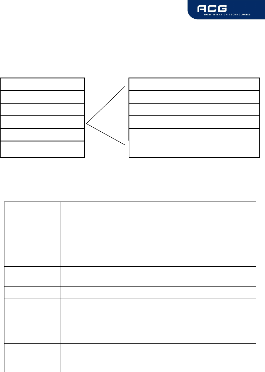
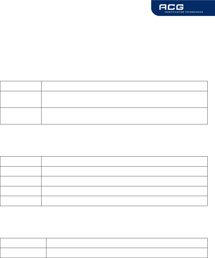
5.2 Mifare Standard
The Mifare Standard card consists of 16 sectors. A sector includes four blocks 16
bytes each.
MIFARE
®
Standard Sector 2
Sector 0 (Block: 0...3) Block 8: Data or value (16 bytes)
Sector 1 (Block: 4...7) Block 9: Data or value (16 bytes)
Sector 2 (Block 8...11) Block 10: Data or value (16 bytes)
...
Sector 15 (Block 60...63)
Block 11: Access Conditions (4
bytes), Key A,
Key B (16 bytes)
Figure 5-2: MIFARE
®
Standard: sector diagram
5.2.1 Definitions
Sector Memory segment of the MIFARE® Standard Card. Each
segment consists of 4 blocks and has individual keys and
access conditions. Typically in a multiapplication
environment each block is assigned to an application.
Key 6 byte structure assigned to each sector of the card. The
reader may store up to 32 keys in its EEPROM or one key in
its RAM.
Transport Key Key as stored after delivery from the manufacturer.(f.e.
A0A1A2A3A4A5, B0B1B2B3B4B5 or FFFFFFFFFFFF)
Block 16 byte memory segment of the MIFARE® Standard card.
Value 4 byte (unsigned long) variable stored in a special format in
a block or page. Values are 2s complement numbers that
can be negative also. Values are used for cashless payment.
Values consume a complete block each using redundancy
for integrity checking.
Card ID 4 byte unique serial number (single size type). Together with
manufacturer code and check byte 16 bytes. Read-only. It Is
stored in block 0 (sector 0) of each tag.

HF Mifare Easy Module V1.0
ACG Identification Technologies GmbH 13
5.2.2 Sector 0 / Block 0
Block 0 is read only.
Serial Number (4 byte)
Check byte (1 byte) Manufacturer data (11 byte)
Figure 5-3: MIFARE Standard: sector 0 / block 0
5.2.3 Block 3, 7, 11, 15, …
Transport keys are set on delivery:
Key A (6 byte) Access Conditions (4 bytes) Key B (6 byte)
Figure 5-4: MIFARE
®
Standard: block 3, 7, 11, 15, …
Key A
A0 A1 A2 A3 A4 A5 (Infineon) or FF FF FF FF FF FF (new Philips cards)
Key B
B0 B1 B2 B3 B4 B5 (Infineon) or FF FF FF FF FF FF (new Philips cards)
Access Conditions
FF 07 80 xx (key A used to read or write, the key A itself is not readable; key B is
data only). For further information refer to Frequently asked questions or Mifare card
manual.
Remarks
Enabled keys are always read as 00 00 00 00 00 00
Using key B as data area will cause a security gap, due to the fact that it is necessary
to rewrite key A and access conditions each write process. It is not recommended to
use it as data storage.
5.3 Mifare Ultralight
Mifare Ultralight cards have no encryption included. They only support plain text data
transmission.
Mifare Ultralight are only supporting 4 byte per sector, but the command set uses 16
byte per sector. Only the 4 least significant bytes are valid when using Mifare
Ultralight.
Ensure that the other bytes matching with tag content when using the write
command, otherwise the read back will fail.
HF Mifare Easy Module V1.0
ACG Identification Technologies GmbH 14
5.4 Mifare 4k
Mifare 4k cards have an increased memory. Beginning from sector 32 (20h) a sector
has 16 blocks. Due to compatibility reasons the sector indices has changed
according following figure. The login sector has to be used to access the according
sector on the card.
Sector Block Login sector
00h 00h – 03h 00h
01h 04h – 07h 01h
… … …
1Fh 7Ch – 7Fh 1Fh
20h 80h – 8Fh 20h
21h 90h – 9Fh 24h
22h A0h – AFh 28h
23h B0h – BFh 2Ch
24h C0h – CFh 30h
25h D0h – DFh 34h
26h E0h – EFh 38h
27h F0h – FFh 3Ch
Figure 5-5: Mifare 4k sector index table
5.5 Mifare ProX
Mifare ProX tags have an operating system onboard. Data organization depends on
the operating system installed on the card. These cards can include additional
functionalities such as DES or a proprietary encipher algorithm.
Prior to any access of the operating system the card must be selected. Customized
commands are issued using the transfer command.
HF Mifare Easy Module V1.0
ACG Identification Technologies GmbH 15
5.6 Mifare DESFire
This tag supports additional security algorithms (DES, Triple-DES, MAC) for security
sensitive applications.
DESFire tags are addressed using a specific command set (see DESFire command
set).
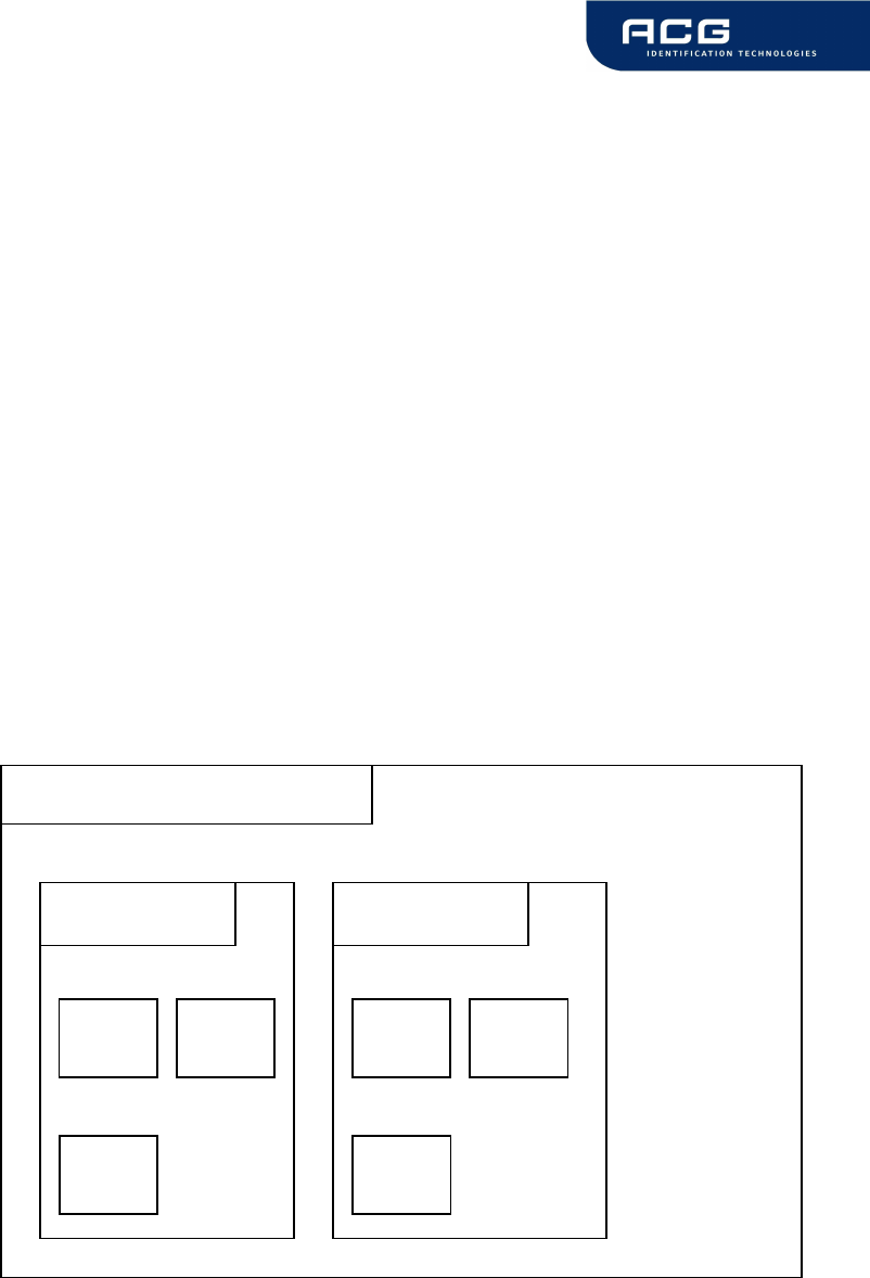
5.6.1 Memory organization
The memory of a DESFire card can be personalized to own requirements. The card
can be seen as data storage like a hard disk in a PC. The memory is divided in up to
28 different applications (directories) and with 16 files each. An application has up to
14 keys. Depending on keys and access conditions a file can be accessed in four
different ways. Plain data is never secured. Data is secured using a MAC, single
DES or triple DES enciphers.
Following figure describes the memory organization of a DESFire card.
Figure 5-6: DESFire memory organization
DESFire card (Applica
tion 0)
Application 1
Application 2
File
ID 1 File
ID 2
File
ID 3
File
ID 1
File
ID 3
File
ID 2
…
… …
HF Mifare Easy Module V1.0
ACG Identification Technologies GmbH 16
5.6.2 State diagram of DESFire
Figure 5-7: DESFire State diagram
5.6.2.1 Activate PICC
Prior to any access to a DESFire card the card must be selected. A DESFire card
has 7 bytes UID. After activation the card is powered up and ready to accept a
DESFire command. Application 0 is selected automatically.
5.6.2.2 Select application with ID
To jump into another application it has to be selected. An application can be seen as
a directory, which contains up to 16 files. The size of the application depends on the
stored files.
5.6.2.3 Login to application
Each application can be set to specific access rights. A login to an application allows
changing the application organization. Login to a file opens a secured file for access.
A file can be accessed in four different ways: plain with no security, secured with
MAC, single DES or triple DES.
Activate DESFire card
Login to application
Select file
Change file
Select application
with ID
Commit / Abort
transaction

HF Mifare Easy Module V1.0
ACG Identification Technologies GmbH 17
5.6.2.4 Select file with ID
Prior to any access to a file a file must be selected
5.6.2.5 Change file
A selected file can be changed according its access rights. If a file is secured a login
is needed before.
5.6.2.6 Commit/ Abort transaction
Value files, backup files, linear record files and cyclic record files only adapt its value
after the commit transaction command. Several files can be changed within an
application at the same time. The abort transactions command annulates all changes
within an application. Power loss will cancel all modifications too.
For more details about the application settings and access rights refer to [2].
HF Mifare Easy Module V1.0
ACG Identification Technologies GmbH 18
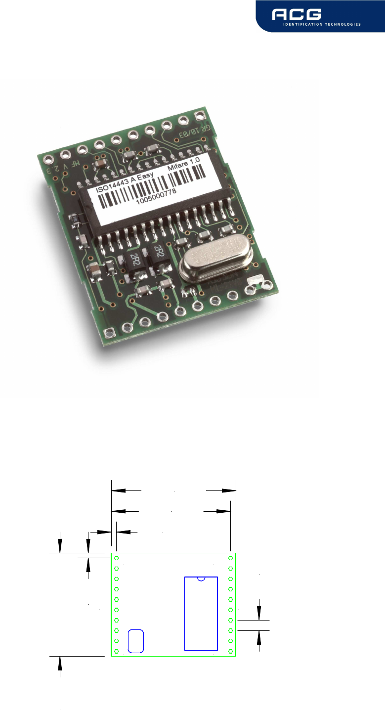
6 Hardware
6.1 Pin out of OEM Module (Top View)
All dimensions are listed in mm.
1
10 11
20
J1 J2
1,27
1,27
25,40
2,54
29,21
30,50

HF Mifare Easy Module V1.0
ACG Identification Technologies GmbH 19
6.1.1 Pin out
PIN PIN Nr Description
ARX 1 Antenna RX
ATX1 2 Antenna TX1
VDD 3 +5 V DC (4.5VDC to 5.5VDC)
GND 4 Ground
ATX2 5 Antenna TX2
TGND 6 Antenna Ground
RFU 7 Reserved for future use
RFU 8 Reserved for future use
RFU 9 Reserved for future use
RFU 10 Reserved for future use
RX 11 RX from PC
TX 12 TX to PC
DIR 13 Direction of RS 485
USER 14 User Port
RES 15 Hardware reset if logic low
EN 16 Enable reader, open or logic high
LEDr 17 LED red
LEDg 18 LED green (reading LED)
GND 19 Ground
VDD 20 +5 V DC (4.5VDC to 5.5VDC)
Figure 6-1: Pin out

HF Mifare Easy Module V1.0
ACG Identification Technologies GmbH 20
6.1.2 Electrical characteristics of PINs
PIN PIN Nr Voltage Current
(max) Description
RX
TX 11
12 USART
1
- To RS232, RS485 or
RS422 device driver
USER 14 TTL
2
25 mA User sets logic state
RES 15 TTL - Hardware reset if logic
low
EN 16 TTL - Low will disable the
reader device
LEDr 17 TTL 25 mA Logic Low, used for LED
LEDg 18 TTL 25 mA With 330 Ω (internal
serial) resistor
ARX
ATX1
ATX2
TGND
1
2
5
6
(depends
on antenna
tuning)
200 mA
PP
Antenna input
Antenna output
Antenna output (GND)
RF-Output: approx
150mW at 50 Ohms
RFU 7,8,9,10 - - Not connected
GND 4,19 GND - Supply Ground
VDD 3,20 +5 V DC
(+4.5V DC
to +5.5
VDC)
150 mA Supply Voltage
DIR 13 TTL 25 mA RS485 direction
Figure 6-2: Electrical characteristics of pins
1
Universal Synchronous Asynchronous Receiver Transmitter
2
TTL buffer output / input
HF Mifare Easy Module V1.0
ACG Identification Technologies GmbH 21
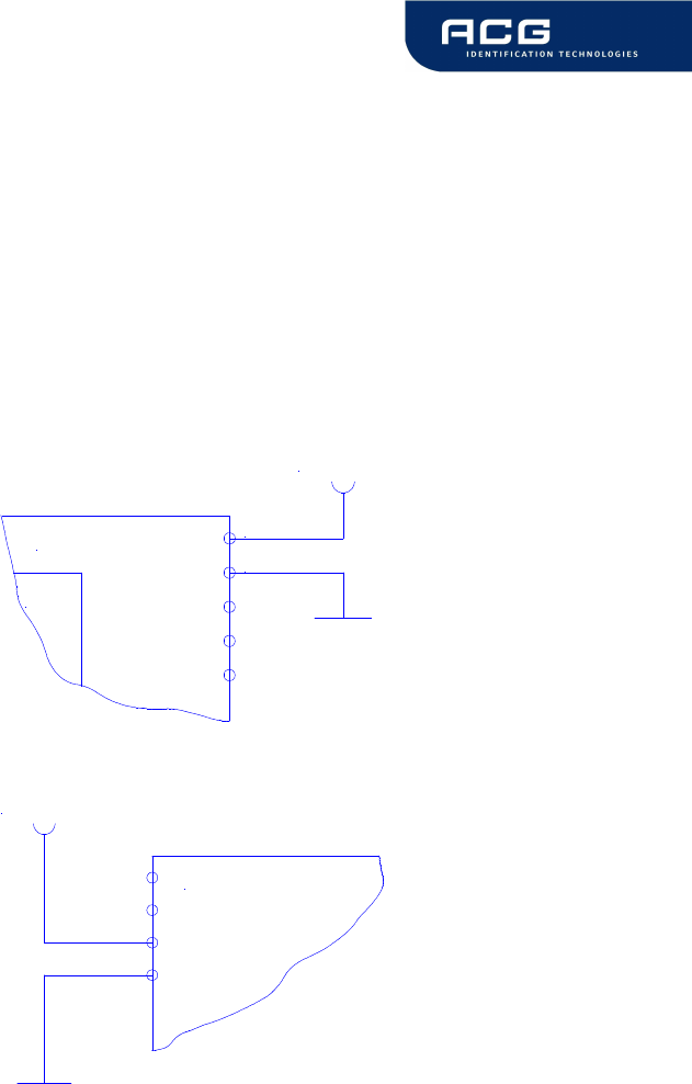
6.1.3 External Connections
6.1.3.1 Power Supply
If the supply voltage and any noise modulated on the supply voltage remains within
the specified limits, no further filtering is required. In some cases it is recommended
to use additional filtering for the power supply line. Insuficcient power line filtering
could cause unexpected or irregular performance drops.
Option 1
uC
20
19
OEM Board
+5V DC
Option 2
3
4
OEM Board
+5V DC
The board can be connected as shown above. Both alternatives are possible and can
be used as they fit best into the layout of the carrier board. The two VCC PINs and
the two GND PINs are connected internally.
HF Mifare Easy Module V1.0
ACG Identification Technologies GmbH 22
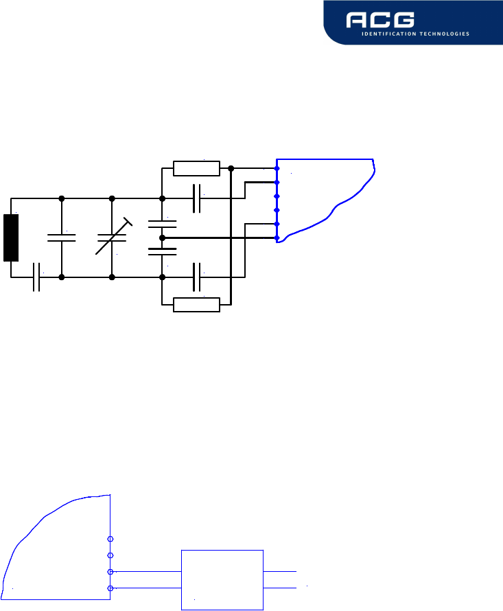
6.1.3.2 Antenna
The antenna tuning and matching network is shown below. Please refer also to the
antenna design guide and to the specific application notes for the reader IC.
6
5
1
2OEM Board
C1
C2
R2
R1
C3
C4
C5
C6
C8
L ANT
6.1.3.3 Serial Interface
The OEM Board can be connected directly with a micro controller. Alternatively the
OEM Board also can be connected to most serial interface types by using the right
interface converter circuit. In order to optimize the communication quality the specific
application note of the interface converter circuit needs to be taken into
consideration.
12
11
Interface
Converter
Circuit Host Interface
OEM Board
HF Mifare Easy Module V1.0
ACG Identification Technologies GmbH 23
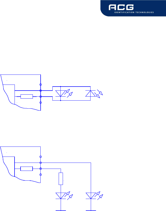
6.1.3.4 Function Control LEDs
Two external LEDs can be connected to the OEM Board. There are two alternatives
possible.
Option 1
uC
330 Ohm
18
17
OEM Board
Option 2
uC
330 Ohm
18
17
330 Ohm
OEM Board
In both cases the LED supply voltage levels are TTL levels.
HF Mifare Easy Module V1.0
ACG Identification Technologies GmbH 24
7 Software
As default data is transmitted at 9600,n, 8,1, no handshaking. Two protocol modes
are supported. The protocol mode is configured in the reader EEPROM. As factory
default, the ASCII protocol is used.
7.1 ASCII Protocol
This protocol is designed for easy handling. The commands are issued using a
terminal program. Data is transmitted as ASCII hexadecimal that can be displayed on
any terminal program (i.e. HyperTerminal).
Command Data
Various length Various length
Figure 7-1: ASCII protocol frame
7.2 Binary Protocol
This protocol is designed for industrial applications with synchronization and frame
checking. Also an addressing byte for party line (master slave, multi drop) is
included.
The protocol usually requires a device driver. Data is transmitted binary. The reader
uses a binary watchdog timer internally to ensure correct framing.
STX Station ID
Length Data BCC ETX
1 byte 1 byte 1 byte Various length 1 byte 1 byte
Figure 7-2: Binary Frame
7.2.1 STX
Start of transmission (02h)
7.2.2 Station ID
Unique ID of the station
00h: reserved for the bus master. Readers send response to this device ID.
FFh: Broadcast message. All devices will execute the command and send its
response.
7.2.3 Length
Data Length Indicator.
Denotes the length of the Data block.
HF Mifare Easy Module V1.0
ACG Identification Technologies GmbH 25
7.2.4 Data
This part contains the command and data. The command values are the same as in
ASCII protocol mode (‘x’, ‘s’, …) whereas data is transmitted binary.
The length of the command block depends on the instruction.
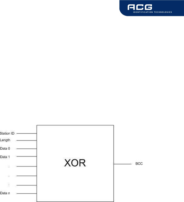
7.2.5 Block Check Character (BCC)
The BCC is used to detect transmission errors. The BCC is calculated XOR-ing each
byte of the transmission frame excluding the STX/BCC and ETX character.
)(...)()()( 0N
DataXORXORDataXORLengthXORStatIDBCC =
7.2.6 ETX
End of transmission. (03h)
7.2.7 Remarks
If the reader device receives an invalid instruction frame (i.e. BCC wrong) or the
requested station ID does not match the internal ID of the reader, the command is
not executed. The reader waits for the next valid frame.
The automatic binary timeout (see protocol configuration register) is used to detect
incomplete binary frames.
The reader module answers in the same telegram format, with the ID-field set to 0.
The Data block of the answers in binary protocol mode does match the ASCII mode
answers, with the only difference that data values are transmitted binary instead of
ASCII Hex.

HF Mifare Easy Module V1.0
ACG Identification Technologies GmbH 26
7.2.8 Examples
02h 64h 01h 78h 1Dh 03h
STX Station ID Length ‘x’ BCC ETX
This instruction frame will reset the reader module with the station ID 64h.
7.3 Register Set
The reader has several system flags to customize its behaviour. The flags are stored
non-volatile in its EEPROM. The reader accepts changes of the setting only during
the start up phase. It is recommended to clear all RFU bits to guarantee further
compatibility.
The reader is able to store up to 32 authentication keys to log in Standard Mifare
cards internally. All keys are read only and cannot be accessed via the interface
lines.
7.3.1 EEPROM memory organization
Register Description
00h … 03h Unique device ID; read only
04h Station ID
05h Protocol configuration
06h Baud rate
07h Reset Off Time
08h Reset Recovery time
09h Internal use / Do no change
0Ah ... 0Fh RFU
10h … 13h User data
Figure 7-3: EEPROM memory
7.3.2 Unique device ID (00h – 03h)
The unique device ID identifies a reader module. It is factory programmed and
cannot be changed.

HF Mifare Easy Module V1.0
ACG Identification Technologies GmbH 27
7.3.3 StationID (04h)
The station ID is used in binary mode to address a device in party line set up. The
station ID has the range of 01h to FEh and can be set freely. The value 00h is
reserved for the bus master. All readers send their response to this device.
The broadcast message (FFh) forces all readers to response to the command.
Default value is 01h.
7.3.4 Protocol configuration (05h)
The protocol configuration register (PCON) specifies general behavior of the reader
device.
Default value is 01h.
Protocol configuration register
Bit 7 Bit 6 Bit 5 Bit 4 Bit 3 Bit 2 Bit 1 Bit 0
RFU RFU RFU Multitag
Binary
Timeout
Extend
ID Binary Auto
Start
Figure 7-4: Protocol configuration register
7.3.4.1 Autostart (default 1)
If set the reader device will start up in continuous read mode automatically.
7.3.4.2 Protocol (default 0)
If set the reader uses binary protocol mode. Refer to binary protocol for further
information on the binary protocol format.
Default setting = ASCII protocol (0).
HF Mifare Easy Module V1.0
ACG Identification Technologies GmbH 28
7.3.4.3 Extended ID (default 0)
This setting does only affect the commands continuos reading (‘c’), select (‘s’) and
multi tag select (‘m’).
If set a the unique serial number of the transponder is extended by a single prefix
byte.
The values for the prefix byte are:
prefix description
01h MIFARE® Light Transponder
02h MIFARE® Standard Transponder
03h MIFARE® 4k Transponder
04h MIFARE® ProX Transponder
05h MIFARE® UltraLight Transponder
06h MIFARE® DESFire Transponder
FFh Unknown Transponder
7.3.4.4 Binary Timeout (default 0)
This flag is only interpreted if the reader operates in binary mode.
If the serial bus stays idle for more than 96 ms (no data is transmitted), the reader will
clear its command buffer and enter “Command Read” mode.
The “Command Read” mode means that the reader is waiting for valid data frames
(beginning with the STX code).
7.3.4.5 Multitag (default 0)
The Multitag flag will enable multi tag recognition in continuous read mode. All tags
are detected and displayed. Due to the more complex search algorithm the
continuous read command decreases its detection speed.
HF Mifare Easy Module V1.0
ACG Identification Technologies GmbH 29
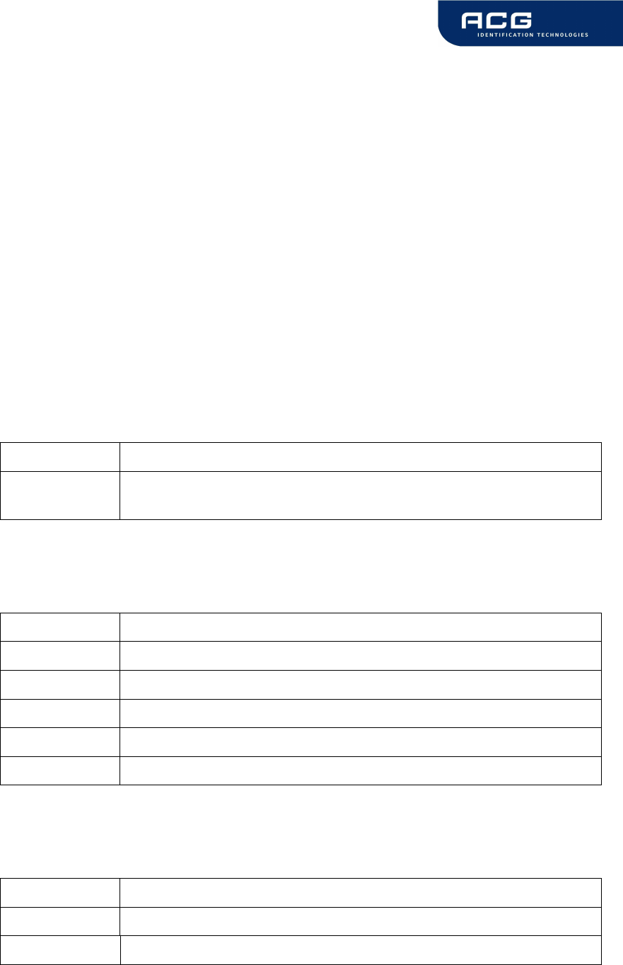
7.3.5 BAUD, Baud rate control register (06h)
The baud rate register defines the communication speed of the reader device.
Default value is 00h.
Baud rate register
Bit 7 Bit 6 Bit 5 Bit 4 Bit 3 Bit 2 Bit 1 Bit 0
RFU RFU RFU RFU RFU RFU BS1 BS0
Figure 7-5: Baud rate register
This register defines the baud rate of the device.
BS1 BS0 Baud rate
0 0 9600 baud (default)
0 1 19200 baud
1 0 38400 baud
1 1 57600 baud
Figure 7-6: Baud rate settings
Following figure describes the communication settings
Description
8 data bits
No parity bit
1 stop bit
No flow control
Figure 7-7: Communication settings
7.3.6 Reset Off Time (07h)
The Reset Off Time register represents the field off time in ms.
This register is used for the select, continuous read and multi tag commands.
Default value is 10h.

HF Mifare Easy Module V1.0
ACG Identification Technologies GmbH 30
7.3.7 Reset Recovery Time (08h)
The Reset Recovery Time register represents the recovery time in ms after the field
is turned on.
This register is used for the select, continuous read and multi tag commands.
Default value is 10h.
7.3.8 User data (10h - 13h)
These registers are for free use.

HF Mifare Easy Module V1.0
ACG Identification Technologies GmbH 31
7.4 Instruction Set
Following table describes all commands of the reader device. Each command returns
an answer to the host. Exceptions are mentioned explicitly. The green LED is
acknowledging a successfully executed command. The red LED indicates an error.
7.4.1 Overview
Common commands
'+' Increment value block (credit)
'-' Decrement value block (debit)
'=' Copy value block (backup)
'c' Continuous read
'g' Get Station ID
'l' Login (authenticate tag)
'm' MultiTag select / tag list
'poff' / 'pon' Antenna power off/on
'pr' / 'pw' Read / write user port
'r' / 'rb' Read block
're' Read EEPROM register
'rv' Read value block
's' Select
'v' Get version
'w' / 'wb' Write block
'we' Write EEPROM register
'wm' Write master key
'wv' Write value block
'x' Reset
Figure 7-8: Command overview

HF Mifare Easy Module V1.0
ACG Identification Technologies GmbH 32
7.4.2 Error Codes
Following figure shows an overview of all error messages of the reader device.
Error Code Description
‘?’ Unknown command
'E' Invalid key format
‘F’ General failure
‘I’ Invalid value format, specified block does not match the value
format
‘N’ No tag in the field
'O' Operation mode failure
'U' Read after write failure
'X' Authentication failed
Figure 7-9: Error codes
HF Mifare Easy Module V1.0
ACG Identification Technologies GmbH 33
7.4.3 Common commands
7.4.3.1 Increment value block (credit)
Increments a value block with a defined value. A read after write is done
automatically to verify data integrity. The command fails if the source block is not in
value block format. A previous log in is needed to access a block.
Command
Command Data
'+' Block (1 byte)
Value (4 bytes)
Answer
Answer Description
Data Value (4 bytes)
'I' Error: value block failure
'F' Error: increment failure
'N' Error: No tag in field
'X' Error: Unable to read after write
Example
Command Description
+0400000001
adds 1 to value block 4
+0500000100
adds 256 to value block 5
7.4.3.1.1 No value block 'I'
Specified block does not match the value format. The value block is corrupted. A
backup block can be used to restore the correct value.
7.4.3.1.2 Increment failure 'F'
General failure during increment procedure or unable to read after write.
7.4.3.1.3 No tag error 'N'
The reader does not detect a response of the tag. There is either no tag present or
the tag does not respond the request.
HF Mifare Easy Module V1.0
ACG Identification Technologies GmbH 34
7.4.3.1.4 Unable to read after write 'X'
The tag was removed from field immediately after increment instruction.
Data was decremented but the tag did not respond to the read after increment
instruction, which is done automatically by the reader module.
7.4.3.2 Decrement value block (debit)
Decrements a value block with a defined value. A read after write is done
automatically to verify data integrity. The command fails if the source block is not in
value block format. A previous log in is needed to access a block.
Command
Command Data
'-' Block (1 byte)
Value (4 bytes)
Answer
Answer Description
Data Value (4 bytes)
'I' Error: value block failure
'F' Error: increment failure
'N' Error: No tag in field
'X' Error: Unable to read after write
Example
Command Description
-0400000001 subtract 1 to value block 4
-0500000100 subtract 256 to value block 5
7.4.3.2.1 No value block 'I'
Specified block does not match the value format. The value block is corrupted. A
backup block can be used to restore the correct value.
7.4.3.2.2 Decrement failure 'F'
General failure during decrement procedure or unable to read after write.
HF Mifare Easy Module V1.0
ACG Identification Technologies GmbH 35
7.4.3.2.3 No tag error 'N'
The reader does not detect a response of the tag. There is either no tag present or
the tag does not respond the request.
7.4.3.2.4 Unable to read after write 'X'
The tag was removed from field immediately after decrement instruction.
Data was decremented but the tag did not respond to the read after decrement
instruction, which is done automatically by the reader module.
7.4.3.3 Copy value block (backup)
Copies a value block to another block of the same sector. A read after write is done
automatically to ensure data integrity. Used for backup and error recovery. A
previous log in is needed to access a block.
Command
Command Data
'=' Source block (1 byte)
Target block (1 byte)
Answer
Answer Description
Data New value of target block (4 bytes).
'I' Error: value block failure
'F' Error: increment failure
'N' Error: No tag in field
'X' Error: Unable to read after write
Example
Command Description
=0405 copy value block 4 to block 5
=0506 copy value block 5 to block 6

HF Mifare Easy Module V1.0
ACG Identification Technologies GmbH 36
7.4.3.3.1 Target block
The target block needs not to be a valid value block. If source block is not in value
format the command fails.
7.4.3.3.2 No value block 'I'
Source value block does not match the value format. The value block is corrupted. A
backup block can be used to restore the correct value.
7.4.3.3.3 Copy failure 'F'
General failure during copy procedure or unable to read after write.
7.4.3.3.4 No tag error 'N'
The reader does not detect a response of the tag. There is either no tag present or
the tag does not respond the request.
7.4.3.3.5 Unable to read after write 'X'
The tag was removed from field immediately after copy instruction.
Data was decremented but the tag did not respond to the read after copy instruction,
which is done automatically by the reader module.
HF Mifare Easy Module V1.0
ACG Identification Technologies GmbH 37
7.4.3.4 Continuous Read
The reader device reads and displays serial numbers continuously while one or more
tags remain in the field. This command stops if any character is sent to the reader
module.
The reader supports different tag types at the same time. To increase the reading
performance switch to a single tag mode. If more than one tag of the same tag type
should be detected at the same time the Multitag flag must be activated. The
response data length depends on the tag type.
Command
Command Data
'c' none
Answer
Answer Description
data serial number (n bytes)
'N' Error: No Tag in the field (only binary protocol)
7.4.3.4.1 Multitag continuous read mode
If the Multitag flag is set in the Protocol Configuration (PCON) register the reader
reads multiple tags continuously.
7.4.3.4.2 Auto start
The continuous read mode is started automatically. The auto start flag must be set in
the PCON register.
7.4.3.4.3 Binary mode
This command is not fully supported in binary protocol mode.
Continuous Read in binary mode does not startup automatically at boot time, even if
the corresponding EEPROM flag is set.
Within the single shot timeout only one response is sent.

HF Mifare Easy Module V1.0
ACG Identification Technologies GmbH 38
7.4.3.4.4 Simple access control applications
Serial numbers are always sent plain. Data encryption is activated after a successful
log in.
For simple access control applications it is recommended to use read-only blocks for
the identification of the tag.
Reading any block (even the manufacturer block) of the transponder will increase
your security.
7.4.3.4.5 Extended ID
If Extended ID is activated a prefix byte extends the serial number. For more
information refer to Protocol Configuration register.
7.4.3.5 Get Station ID
This command returns the station ID of the reader device. The answer is time slotted
to enable that all devices in party line mode are detected.
The station ID has only effect in binary mode.
Command
Command Data
'g' None
Answer
Answer Description
Data Station ID of the reader device (1 byte)
HF Mifare Easy Module V1.0
ACG Identification Technologies GmbH 39
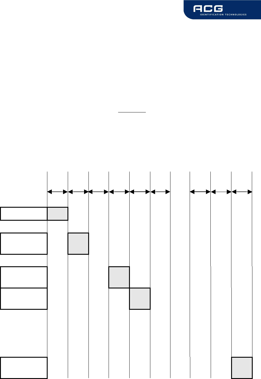
7.4.3.5.1 Time slotted answer
In party line mode more than one reader can be used simultaneously. The time
slotted answer allows separating all connected devices. The station ID is used to
determine the correct time slot.
The reader supports up to 254 unique time slots. Following formula calculates the
needed time of one time slot. Only one baud rate on the same party line is supported.
6*
10
][
0
Baudrate
sT =
Figure 7-10: Time slot formula
Following figure shows the timing diagram of time slotted answers.
timeslot 0 1 2 3 4 5 … 252 253 254
T
0
T
1
T
2
T
3
T
4
T
5
T
253
T
254
T
255
HOST 'g'
→
reader (01)
←
01
reader (03)
←
03
reader (04)
←
04
reader (254)
←
254
Figure 7-11: Timing diagram of time slotted answers

HF Mifare Easy Module V1.0
ACG Identification Technologies GmbH 40
7.4.3.6 Login (authenticate tag)
Performs an authentication to access one sector of a Mifare
®
card. Only one sector
can be accessed at the same time.
Optionally to transmit the key data to the reader stored keys, in the reader EEPROM,
can be used.
To store keys in the EEPROM the write master key command is used. It is possible
to store up to 32 master keys in the reader EEPROM. The login requires a successful
select.
Command
Command Data
'l' Sector (1 byte) ), valid range 00h - 3Fh
Key type (1 byte)
AAh authenticate with key type A
FFh authenticate with key type A, transport key
FFFFFFFFFFFFh
BBh authenticate with key type B
10h … 2Fh authenticate with key type A using stored
key (00h … 1Fh)
30h … 4Fh authenticate with key type B using stored
key (00h … 1Fh)
Key (6 bytes) / <CR> (1 byte), optional
By transmitting <CR> instead of the keydata
authentication is done with manufacturers transport
keys (A0A1A2A3A4A5h, B0B1B2B3B4B5h,
FFFFFFFFFFFFh).
Answer
Answer Description
data Login status (1 byte)
'L' Login success
'E' Error: Invalid key format
'F' Error: General failure
'N' Error: No tag

HF Mifare Easy Module V1.0
ACG Identification Technologies GmbH 41
Example
Command Description
l02AA<CR> Authenticate for sector 2, using the transport key A
(A0A1A2A3A4A5h, key type A)
l3FBB<CR> Authenticate for sector 63, using the transport
key 2 (B0B1B2B3B4B5h, key type B)
l04FF<CR> Authenticate for sector 4, using the transport key 3
(FFFFFFFFFFFFh, key type A)
l0FAAFFFFFFFFFFFF Authenticate for sector 15, using key
FFFFFFFFFFFFh, key type A
l0E14 Authenticate for sector 14, using EEPROM key 4,
key type A
l0530 Authenticate for sector 5, using EEPROM key 0,
key type B
l0732 Authenticate for sector 7, using EEPROM key 2,
key type B
l0110 Authenticate for sector 1, using EEPROM key 0,
key type A
l0ABBFF12FFFFFF35 Authenticate for sector 10, using key
FF12FFFFFF35h, key type B
7.4.3.6.1 No tag error 'N'
The reader does not detect a response of the tag. There is either no tag present or
the tag does not respond the request.
7.4.3.6.2 <CR>
Three transport keys are implemented to access cards fast.
Transmitting <CR> instead of the key the reader module uses transport keys for the
login procedure.
Command Description
LxxAA<CR> Authenticate for sector xx, using the transport
key A (A0A1A2A3A4A5h, key type A)
LxxBB<CR> Authenticate for sector xx, using the transport key 2
(B0B1B2B3B4B5h, key type B)
LxxFF<CR> Authenticate for sector xx, using the transport key 3
(FFFFFFFFFFFFh, key type A)
HF Mifare Easy Module V1.0
ACG Identification Technologies GmbH 42
7.4.3.6.3 Login with keydata from EEPROM
Each key stored in the reader EEPROM can be used as keytype A or keytype B. To
use a key as type A the value 10h must be added to the key index. 30h must be
added to use a key as type B.
7.4.3.6.4 Usage of key A, key B
Mifare
®
cards support two different crypto keys for each sector. Each key is 32 bit
long and is stored in the sector trailer (last block of the sector) on a card. It is
possible to set different access rights for each key.
7.4.3.7 Multi Tag Selection / List
This command detects several tags at the same time. It replaces the fast select
command ('s') in multiple tag surroundings. The Multi Tag list command lists all tags
with its serial numbers. Use the Multi Tag Select command to select a single tag.
Each tag has to be selected separately.
Command
Command Data
'm' Serial number (n bytes)
<CR> (1 byte)
Answer
Answer Description
Data serial number
'N' Error: No Tag in the field
Example
Command Description
m<CR> 04E9E700000000 first card
34030F07 second card
02 number of detected tags
m04E9E700000000<CR> Select card with its serial number

HF Mifare Easy Module V1.0
ACG Identification Technologies GmbH 43
7.4.3.7.1 Multi tag list
Sending a <CR> as first parameter the reader returns a list of all present tags in the
antenna field. In the end the amount of detected tags are returned.
7.4.3.7.2 Reading distance
Each card needs a specific amount of power. The reader always provides the same
power. Therefore the reading distance will decrease if more tags are present.
Basically, the reading distance depends on the used tag, antenna and its tuning.
7.4.3.7.3 Multi tag select
Using the serial number with <CR> as parameter the according tag will be selected.
High-level interactions can be performed addressing only this card. All other tags
remain silent.
7.4.3.7.4 Multi tag reset
The antenna field reset can be deactivated with Protocol configuration 2 register.
By suppressing the antenna field reset it is possible to detect only new tags in the
antenna field.
7.4.3.7.5 Maximum number of tags
The maximum number of tags in the antenna field is limited to the physical
characteristics of the antenna.
The implementation detects up to 16 tags.
HF Mifare Easy Module V1.0
ACG Identification Technologies GmbH 44
7.4.3.8 Antenna power on/off
This command controls the antenna power. It can be used to decrease the power
consumption of the reader.
Command
Command Data
'pon' Switch on reader
'poff' Reader enters the stand by mode
Answer
Answer Description
'P' Positive acknowledge
Example
Command Description
poff Reader enters stand by mode
7.4.3.8.1 Power off
The reader enters the stand by mode. Power consumption is decreased. All tags in
the antenna field are powered off and reset. The stand by mode is only entered
manually.
To switch off the whole unit pin 16 (Enable) has to be set to logic low.
7.4.3.8.2 Power on
The reader leaves the stand by mode and is ready for the next command. Sending a
tag command (i.e. select, continuous read) the reader is powered up.
7.4.3.8.3 Reset Timing
The power up timing depends on environmental conditions such as voltage ramp up.

HF Mifare Easy Module V1.0
ACG Identification Technologies GmbH 45
7.4.3.9 Read/Write user port
This command sets or reads the state of the user port (pin 14) of the OEM reader
device. The port is set either as output or as input.
Command
Command Data
'pr' none
'pw' State of user port (1 Byte)
Answer
Answer Description
Data State of user port (1 Byte)
Example
Command Description
pr Reads user port
pw01 Sets user port state to high
7.4.3.9.1 Read port
The port read command returns the current state of the USER port.
Port state Description
00 USER port is low
01 USER port is high
Figure 7-12: Read USER port return values
HF Mifare Easy Module V1.0
ACG Identification Technologies GmbH 46
7.4.3.9.2 Write port
If user port is used as an output a 1k
Ω
resistor has to be integrated into the wire.
Otherwise the reader device can be damaged.
Port state Description
00 Sets USER port to low
01 Sets USER port to high
Figure 7-13: Write User port settings
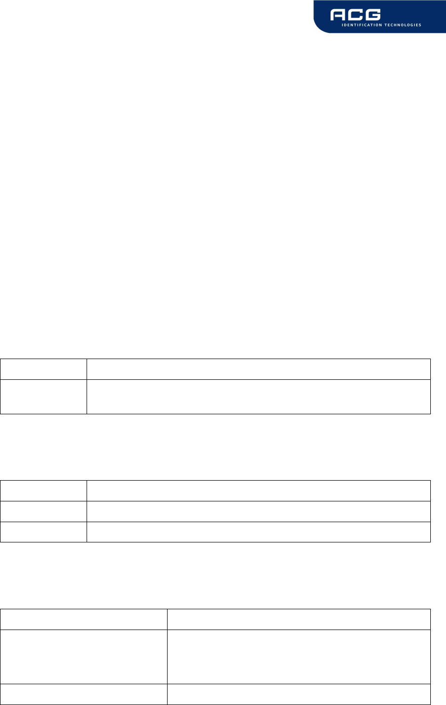
7.4.3.10 Read block
This command reads a data block on a card. Size of returned data depends on the
used tag. The block address range depends on the present tag.
Command
Command Data
'r' Block address (1 byte), valid range 00h – 40h
'rb' Block address (1 byte)
Answer
Answer Description
Data block data (depends on tag type)
'F' Error: read failure
'N' Error: No tag in field
'O' Error: Operation mode failure
Example
Command Description
rb05 Reads block 05.

HF Mifare Easy Module V1.0
ACG Identification Technologies GmbH 47
7.4.3.10.1 Read failure 'F'
This error is returned if the reader receives either bad data or the block address
exceeds the block address range of the sector.
7.4.3.10.2 No tag in field 'N'
The tag does not respond. There is either no tag present or not addressed.
7.4.3.10.3 Operation mode failure 'O'
The block address of the 'r' command is higher than 40h.
The block address of the 'r' command conflicts with other commands, therefore the
block address has to be limited to 40h.
Use the 'rb' command instead.
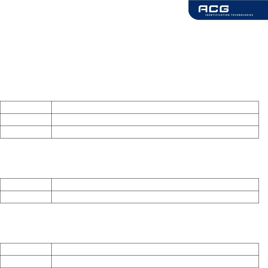
7.4.3.11 Read reader EEPROM
This command reads the internal reader EEPROM. It contains all startup parameters
and the device ID. Changes of the startup settings will only be taken into effect after
a reset of the device.
Command
Command Data
're' EEPROM address (1 byte) 00h … 13h
Answer
Answer Description
Data EEPROM data (1 byte)
Example
Command Description
rp05 Reads protocol configuration register.

HF Mifare Easy Module V1.0
ACG Identification Technologies GmbH 48
7.4.3.12 Read value block
Reads a value block. The command checks if data is in value block format. The read
value block command needs a successful login.
Command
Command Data
'rv' Value block (1 byte)
Answer
Answer Description
Data Read value (4 bytes)
'F' Error: General failure
'I' Error: value block failure
'N' Error: No tag in field
Example
Command Description
rv04 Reads value of block 4.
7.4.3.12.1 No value block 'I'
The value read back after the write value instruction is a not a value block. Data was
written corruptly.
7.4.3.12.2 No tag error 'N'
This means that the tag does not respond, because there is either no tag present or
none of the tags in the field is authenticated ('l' instruction).
7.4.3.12.3 General failure 'F'
Additional to a data read error caused by bad transmission conditions, this error
appears if a sector is addressed which is not located in the authenticated sector.
HF Mifare Easy Module V1.0
ACG Identification Technologies GmbH 49
7.4.3.13 Select
This command selects a single card in the antenna field. It can only be used in single
tag mode. In the case of success the command returns the UID of the selected card.
The reader detects the length of the card automatically.
Command
Command Data
's' None
Answer
Answer Description
Data serial number
'N' Error: No Tag in the field
Example
Command Description
s 1234567890ABCD
Select the card with its UID 1234567890SABCD.
7.4.3.13.1 Select a single tag
No previous continuous read is required. The command executes an automatic field
reset.
7.4.3.13.2 Extended ID
For more information of the Extended ID refer to Protocol configuration register.
7.4.3.13.3 Multiple tags
This command is designed for fast access of a single tag in the field. If multiple cards
are used the 'm' instruction has to be used instead.
HF Mifare Easy Module V1.0
ACG Identification Technologies GmbH 50
7.4.3.14 Get Version
This command returns the current version of the reader module.
Command
Command Data
'v' None
Answer
Answer Description
'Mifare 1.0' + <CR> + <LF> ASCII Mode
02 00 0A 4D 69 66 61 72 65 20 31 2E 30 31 03 Binary Mode
Example
Command Description
v ‘Mifare 1.0’
Version of the reader module
HF Mifare Easy Module V1.0
ACG Identification Technologies GmbH 51
7.4.3.15 Write block
This command writes data to a block. A read after write is done automatically to
ensure correct writing.
Command
Command Data
'w' Block address (1 byte), valid range 00h – 40h
Data (n bytes)
'wb' Block address (1 byte)
Data (n bytes)
Answer
Answer Description
Data Block data (depends on tag type)
'F' Error: Write failure
'N' Error: No tag in field
'O' Error: Operation mode failure
Example
Command Description
wb0511223344 Writes data 11223344 on block 05.
7.4.3.15.1 Write failure 'F'
This error is displayed if bad transmission conditions are given. If the block address
exceeds the physical number of blocks of a tag this error is thrown.
7.4.3.15.2 No tag error 'N'
This error is returned if no tag is present or the card does not respond.

HF Mifare Easy Module V1.0
ACG Identification Technologies GmbH 52
7.4.3.15.3 Operation mode failure 'O'
The block address of the 'w' command is higher than 40h.
The block address of the 'w' command conflicts with other commands, therefore the
block address has to be limited to 40h.
Use the 'wb' command instead.
7.4.3.16 Write EEPROM
Writes to the internal reader EEPROM. It contains all startup parameters and the
device ID. Changes of the startup settings will only be taken into effect after a reset
of the device.
Command
Command Data
'we' Address (1 byte), valid range 04h - 13h
Data (1 byte)
Answer
Answer Description
Data EEPROM data (1 byte)
'F' Error: Read after write failure
Example
Command Description
we0401 Set EEPROM address 04 (Station ID) to 01h
HF Mifare Easy Module V1.0
ACG Identification Technologies GmbH 53
7.4.3.17 Write master key
This command stores a MIFARE Standard key into the master key memory of the
reader. The reader can store up to 32 keys.
Command
Command Data
'wm' Key number (1 byte) 00h … 1Fh
Key (6 bytes)
Answer
Answer Description
data written key (6 bytes)
'F' Error: Write failure
Example
Command Description
wm00112233445566 Store key 112233445566h in EEPROM (key
number 0).
wm02A0A1A2A3A4A5 Store transport key 1 in EEPROM key 2.
7.4.3.17.1 Writing master keys
Keys are write only. It is not possible to read the keys. Nevertheless the reader
returns correct error messages if the writing process fails.
A verification of the master key can only be done using an appropriate card and a
successful login.
7.4.3.17.2 Using master keys for authentication
Master keys may be used for ISO-14443 A tag authentication. It is possible to use
every stored for key A as well as key B authentication.
Each key is 6 bytes long and stored redundantly for data security.
HF Mifare Easy Module V1.0
ACG Identification Technologies GmbH 54
7.4.3.18 Write value block
This command formats a block as a value block containing a 32-bit value. A read
after write is performed automatically. Value blocks need a complete 16-byte block
due to redundant storage. A successful login is required to run the command.
Command
Command Data
'wv' Value block (1 byte)
Value (4 bytes)
Answer
Answer Description
Data Written value (4 bytes)
'I' Error: value block failure
'F' Error: increment failure
'N' Error: No tag in field
'U' Error: Read after write failure
Example
Command Description
wv05010055EF Writes value 010055EFh to block 5.
7.4.3.18.1 Invalid value 'I'
The value read back after the write value instruction is a not a value block. Data was
written corruptly.
7.4.3.18.2 Write failure 'F'
Additional to a data read error caused by bad transmission conditions, this error
appears if a sector is addressed which is not located in the authenticated sector.
7.4.3.18.3 No tag error 'N'
This error is returned if no tag is present or the card does not respond.
HF Mifare Easy Module V1.0
ACG Identification Technologies GmbH 55
7.4.3.18.4 Writing values
The write value block command is designed to create blocks, which match the value
format. This command requires write access to specified block. It is not
recommended to use this instruction for ticketing operations. For ticketing
applications special instructions (Increment/Decrement/Copy) are supported.
7.4.3.19 Reset
This command executes a power on (software) reset. New configuration settings will
be loaded. It resets all tags in the antenna field.
Command
Command Data
'x' None
Answer
Answer Description
'Mifare 1.0' + <CR> + <LF> ASCII Mode
None Binary Mode
7.4.3.19.1 Reset Timing
The power up timing depends on environmental conditions such as voltage ramp up.
For handheld devices the timing can change on the charging state of the battery.

HF Mifare Easy Module V1.0
ACG Identification Technologies GmbH 56
8 Frequently Asked Questions
8.1 Getting Started
To test and interface the Mifare Easy Module, you do not need a sophisticated µP
development system. All you need is a PC, a connection cable and a power supply
for the reader. If you are using Microsoft Windows (95/98/NT/…), take the following
steps:
•
Make sure, that your reader is RS232-interface type
•
Start HyperTerminal
•
Create a new connection (FILE/NEW CONNECTION)
•
Enter name of connection as you like (i.e. ‘MIFARE’)
•
Select connect COM2 (COM1) direct connection
•
Connection setup 9600,8,n,1,no handshake
•
Connect your reader to COM2 (COM1) of the PC and apply appropriate the
supply voltage. The reader transmits a string (“Mifare 1.0”) to the PC.
•
This String denotes the firmware provided by your reader module
•
Put a tag to your reader. Serial numbers should be displayed properly
•
Enter commands via keyboard. They should be transmitted to the reader and
the reader should reply
If using an operating system different from Microsoft Windows you may use any other
terminal program which is capable of receiving/transmitting data via the serial port of
your PC.
8.2 How should the Mifare Easy Reader be personalized?
In ASCII protocol applications, no personalization is necessary.
In applications that are using the binary protocol mode a personalization procedure is
required. Use the Utility program to set up your reader correctly. Ask the reseller or
the next ACG ID sales representative of the Reader for the Utility software or
download it from www.acg.de. It requires at minimum WIN98SE, and a COM port on
the PC.

HF Mifare Easy Module V1.0
ACG Identification Technologies GmbH 57
8.3 What type of Mifare® card should I use?
Mifare
®
Standard is designed for multi application environment. It contains 16 sectors
each with 2 individual keys, access conditions, 3 data or value blocks. Some
applications use the 1 Kbytes of the Mifare
®
Standard Card Memory just as storage.
Mifare Ultralight has not a crypto unit on chip. It only supports 16 blocks.
Mifare Standard 4k cards have the same features as Mifare Standard card but
increased memory capacity.

HF Mifare Easy Module V1.0
ACG Identification Technologies GmbH 58
8.4 How safe is Mifare® Standard for cashless payment?
Security is always a property of the overall system, not of the components. It requires
careful design.
A properly designed system will require ALL barriers to be hacked in order to be
broken.
For good design start specifying feasible attacks. Then create barriers to block them.
Mifare
®
was specifically designed for cashless payment applications. The Mifare
®
concept provides following barriers:
•
Anticollision/-selection
•
Atomic value transaction
•
Ciphered communication
•
Storage of values and data protected by mutual authentication
•
Weak field keys that allow decrement only
•
Stored keys in the reader that are not readable
•
Keys in the card that are not readable
•
A brute force attack by trying different keys is limited by the transaction time
(several msec) of the card and would last virtually forever.
•
etc.
The Application can and should provide more barriers:
•
Sector access conditions. It is possible to assign access conditions in a way
that only decrementing of values is allowed with the keys used in the field. So
even a manipulated field station cannot be used to charge cards with
additional values. As a rule, key A is used as a field key, allowing decrement
and read only, and key B to format the card or charge values.
•
Diversified keys. To make life even harder for attackers, keys can be modified
using serial number and memory content of the card. So each card uses
different keys and a listening attack on the reader interface would be
hopeless.
•
Limiting cash volume stored on a card
•
Do not use the transport keys (keys as programmed after delivery) for ticketing
applications!
•
Ciphered and scrambled data storage
•
Sabotage alarm
•
etc.
•
Even higher security with contactless controller cards like DESFire,
MifareProX, Smart MX etc.

HF Mifare Easy Module V1.0
ACG Identification Technologies GmbH 59
8.5 Mifare® Standard Sector Trailer and Access Conditions
The last block of each sector contains configuration data for the sector. This
configuration data includes key A, key B and the access conditions. The first six byte
(byte 0…5) of the Sector Trailer contain key A data, the last six bytes (byte 10…15)
contain key B data.
Byte number 6 to byte number 9 contain the access conditions for each block of the
sector. It is possible to configure the access rights (read, write, increment,
decrement, restore) different for each block in the sector and in dependence to the
key used in the authentication (login) procedure.
Access conditions for the Sector Trailer himself are different form access conditions
of a data block (increment, decrement, copy is never allowed for the Sector Trailer as
of course this block never contains value data). The access conditions are stored
redundant for data security reasons.
Please consider that enabled keys are not readable and therefore return 00 on
reading.
It is possible to configure each block of one sector as Value Block (Ticketing) or Data
Block.
As an example you may use the following values for the access rights:
Block 0 Block 1 Block 2 Sector Trailer
V V V 08 77 8F FF
V V D 48 77 8B FF
V D V 28 77 8D FF
V D D 68 77 89 FF
D V V 18 77 8E FF
D V D 58 77 8A FF
D D V 38 77 8C FF
D D D 78 77 88 FF
Where “D” denotes a data block and “V” value block. All access conditions are
configured that way that key B has write access to the Sector Trailer and so may
change the configuration.
Each of the 16 sectors consists of 4 blocks (including the sector trailer). Block 0 of
sector 0 contains the serial number and some manufacturer data. It is read only.
For detailed description of the Sector Trailer /Access Conditions please refer to the
datasheets of your chip manufacturer. As it is possible to destroy the tag
(permanently make a block read and write protected) it is strongly recommended not
to change the Sector Trailer without detailed knowledge and under safe environment
with good reading/writing only.

HF Mifare Easy Module V1.0
ACG Identification Technologies GmbH 60
8.5.1 Examples
8.5.1.1 Ticketing Applications
For ticketing applications it is recommended to use both keys of the MIFARE® card.
Key A as a field key with rights for read, copy and decrement only. Key B is used as
master key with full access rights (including increment and changing the access
conditions and keys).
8.5.1.2 Data Handling Applications
For data handling Applications it is recommended to disable ticketing operations
(increment, decrement, copy). Key A is user as slave key with reading rights only.
Key B is used as master key with read/write access to all blocks.
8.5.1.3 No Security, open configuration
For open configuration applications it always possible not to change the sector trailer
(FF 07 80 xx) and use the configuration as defined by the card manufacturer.
Key A is set as master key with full access rights and key B is disabled.
8.6 Using a Mifare card
This example demonstrates detecting a card in the antenna field with continuous
read and additional reading of a page.
Command Answer
c Activate continuous read mode
B2197B58
a card responses with his serial number
. S
abort continuous read mode
s B2197B58
select card
l01AAFFFFFFFFFFFF L
login into sector 1 with key
FFFFFFFFFFFFh key type A
rb04 00112233445566778899AABBCCDDEEFF
read block 04
c Activate continuous read mode to detect a
new card
Figure 8-1: Using a Mifare card

HF Mifare Easy Module V1.0
ACG Identification Technologies GmbH 61
9 References
[1] ISO/IEC 14443 Part 1-4, Identification Cards – Contactless integrated
circuit(s) cards – Proximity cards
[2] DESFire Documentation, Philips, http://www.semiconductors.philips.com
[3] ACG Antenna Design Guide
[4] Philips; Application Note, Mifare® & I-Code, Micore Reader IC family Directly
Matched Antenna Design

HF Mifare Easy Module V1.0
ACG Identification Technologies GmbH 62
10 Appendix A: Antenna
According to antenna design, please refer to Philips Application Note (Mifare ® & I-
Code, Mifare Reader IC family Directly Matched Antenna Design [4]) or to the ACG
Antenna Design Guide [3].
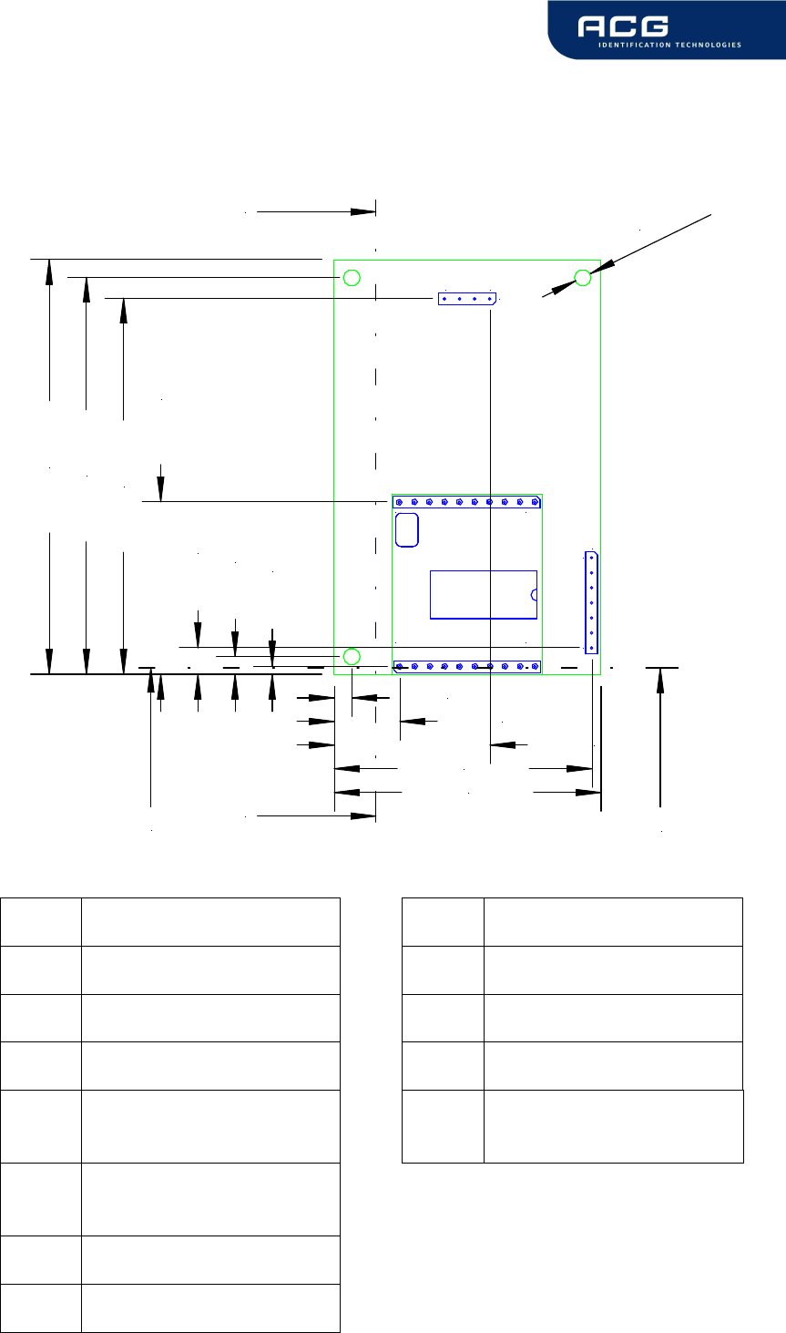
HF Mifare Easy Module V1.0
ACG Identification Technologies GmbH 63
11 Appendix B: Compact P&P Module
All dimensions in mm
1
10 11
20
1
7J3
J4
1
4
1,36 mm
3,00 mm
4,50 mm
29,13 mm
63,50 mm
67,00 mm
70,00 mm
3,00 mm
11,07 mm26,31 mm
43,50 mm
45,00 mm
ø 2,80 mm
A
A'
B'
B
Connector J3: Connector J4:
Pin Description Pin Description
1 Reserved 1 Read LED +
2 +5V 2 Read LED –
3 GND 3 Power LED –
4 RX (RS232) / RXA
(RS422) 4 Power LED +
5 TX (RS232) / TXA
(RS422)
6 RXB (RS422)
7 TXB (RS422)

HF Mifare Easy Module V1.0
ACG Identification Technologies GmbH 64
9,00 mm
J4
View A-A'
9,00 mm
1,60 mm
3,10 mm
J3
View B-B'
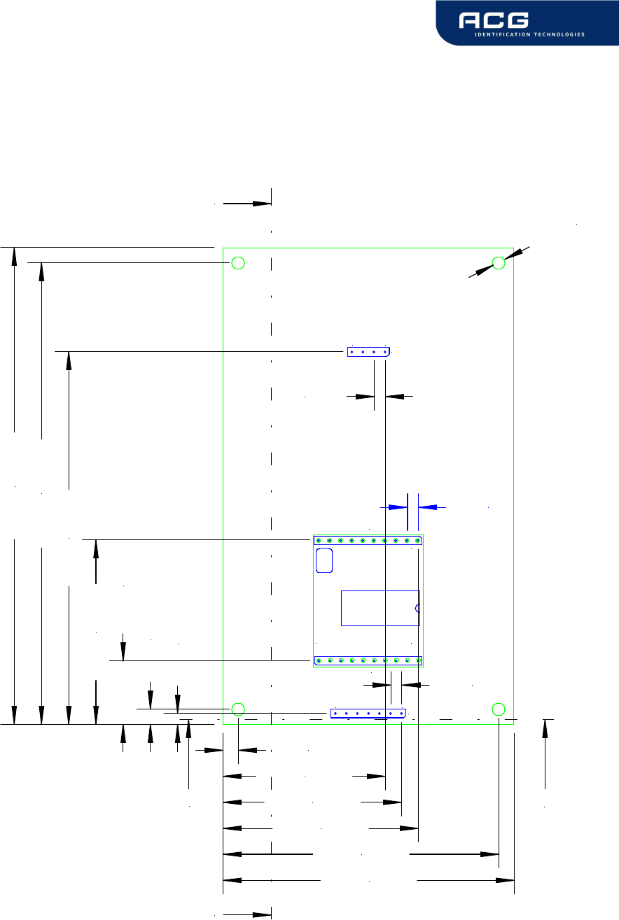
HF Mifare Easy Module V1.0
ACG Identification Technologies GmbH 65
12 Appendix C: Short Range P&P Module
All dimensions are listed in mm.
1
10 11
20
1
7J3
J4
2,54 mm
3,50 mm
14,60 mm
42,54 mm
85,96 mm
106,50 mm
110,00 mm
3,50 mm
37,31 mm
41,12 mm
44,88 mm
63,50 mm
67,00 mm
2,54 mm
2,54 mm
2,54 mm
ø 3,00 mm
41
A'
A
B
B'
J1
J2
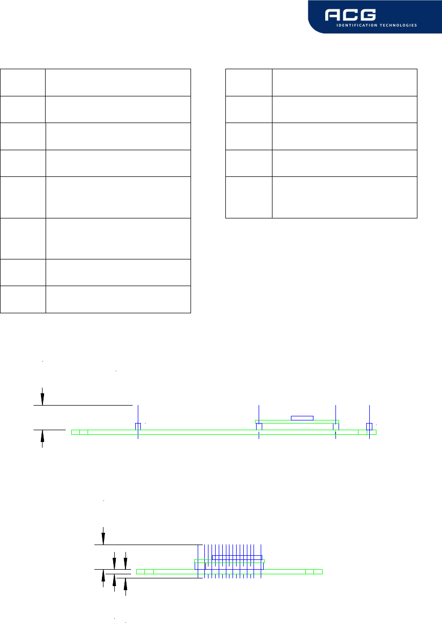
HF Mifare Easy Module V1.0
ACG Identification Technologies GmbH 66
Connector J3: Connector J4:
Pin Description Pin Description
1 Reserved 1 Read LED +
2 +5V 2 Read LED –
3 GND 3 Power LED –
4 RX (RS232) / RXA
(RS422) 4 Power LED +
5 TX (RS232) / TXA
(RS422)
6 RXB (RS422)
7 TXB (RS422)
J4
View A-A'
J3
9,00 mm
9,00 mm
1,60 mm
3,10 mm

HF Mifare Easy Module V1.0
ACG Identification Technologies GmbH 67
13 Appendix D: Timings
t
CMD
t
EXEC
t
RES
PC: Request
→
Reader:
←
Response
Command t
EXEC
[ms]
Comments
Common commands
cont. read 7 + Reset Off and Recovery Time
multiselect 10 + Reset Off and Recovery Time
multiselect (no tag) 35.4 + Reset Off and Recovery Time
antenna on 0.5
antenna off 0.6
port read 0.3
port write 0.3
read block 4.1
write block 11.6
reset 107
select 8.8 + Reset Off and Recovery Time
select (no tag) 35.4 + Reset Off and Recovery Time
increment value block 15.1
decrement value block 15.1
copy value block 15
read value block 4
write value block 15.5
Power conditions
Power on 145 excluded raising time of power supply
Enable on 114
Figure 13-1: Timings
All timing data is advisory application information and does not form part of the
specification. It may change in further firmware releases. Please note also that all in
the above table specified values depend on the used tag.

HF Mifare Easy Module V1.0
ACG Identification Technologies GmbH 68
14 Appendix E: Release Notes
14.1 Version History
14.1.1 Mifare 1.0
Initial Release.
14.2 Revision history
Date Revision number
04/13/2005 Version 1.0, Rev. 1.0
10/07/2005 Version 1.0, Rev. 1.1

HF Mifare Easy Module V1.0
ACG Identification Technologies GmbH 69
15 Appendix F: CE Declaration
The HF Mifare Easy Plug & Play Read/Write Module complies with the European CE
requirements specified in the EMC Directive 89/336/EEC. The relevant documents
are available.
If the HF Mifare Easy Read/Write Module is operated from a mains power supply, all
power connections and additional components of the final device must comply with
the European EMC directive.
Additional connections may have a length of up to 2 m maximum, or in fixed
installations up to 1 m maximum.
European customers must themselves make sure that the final device conforms to
the European EMC Directive.

HF Mifare Easy Module V1.0
ACG Identification Technologies GmbH 70
16 Appendix G: FCC Declaration
The HF Mifare Easy Plug & Play Read/Write Module complies with the US FCC Part
15 requirements. The relevant documents are available.
If the HF Mifare Easy Read/Write Module is operated from a mains power supply, all
power connections and additional components of the final device must also comply
with the US FCC Part 15 directive.
Customers selling into the USA must themselves make sure that the final device
conforms to the US FCC Part 15 directive.
Caution: Any changes or modifications not expressly approved by the party
responsible for compliance could void the user’s authority to operate the
equipment.
The final product should contain labelling according to FCC requirements.
For example: This device complies with Part 15 of the FCC rules. Operation is
subject to the following two conditions: (1) This device may not cause harmful
interference, and (2) this device must accept any interference received, including
interference that may cause undesired operation.
This device contains FCC ID RJPRDHC-0502N0-0X.
This label will be placed on the final product, clearly visible to all persons exposed to
the transmitter.