ASSALOY AH20R02 Wireless Communication Hub User Manual
ASSA ABLOY AB Wireless Communication Hub
UserManual.wiki
>
ASSALOY
>
AH20R02 User Manual
User Manual
Navigation menu
Upload a User Manual
Namespaces
Wiki Guide
HTML
PDF
Info
Views
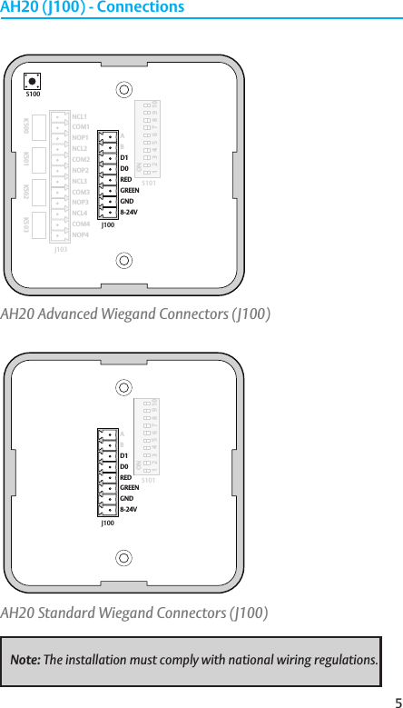
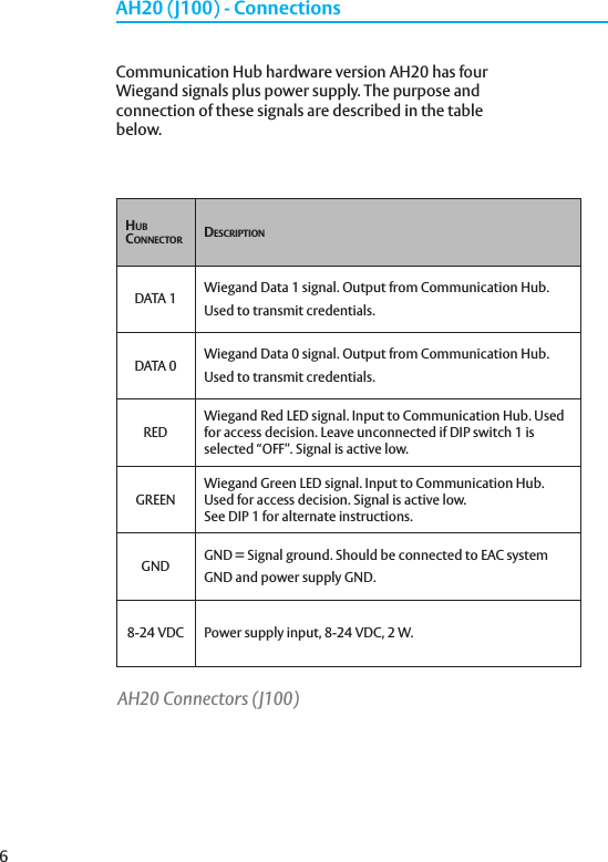
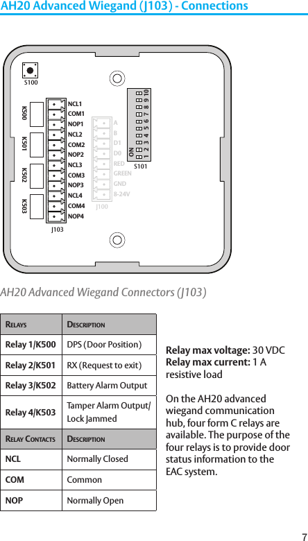
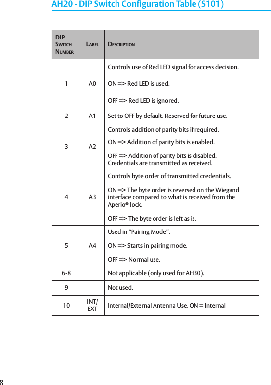
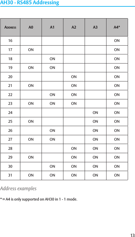
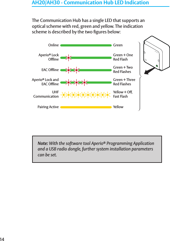
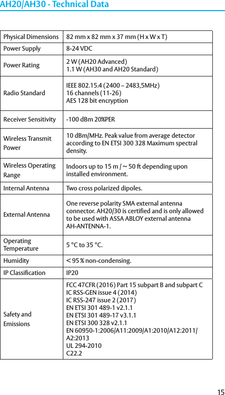
User Manual
Discussion / Help
Navigation