ASSALOY AH40R02 Wireless Communication Hub User Manual
ASSA ABLOY AB Wireless Communication Hub
ASSALOY >
User Manual
1
ASSA ABLOY, the global leader
in door opening solutions
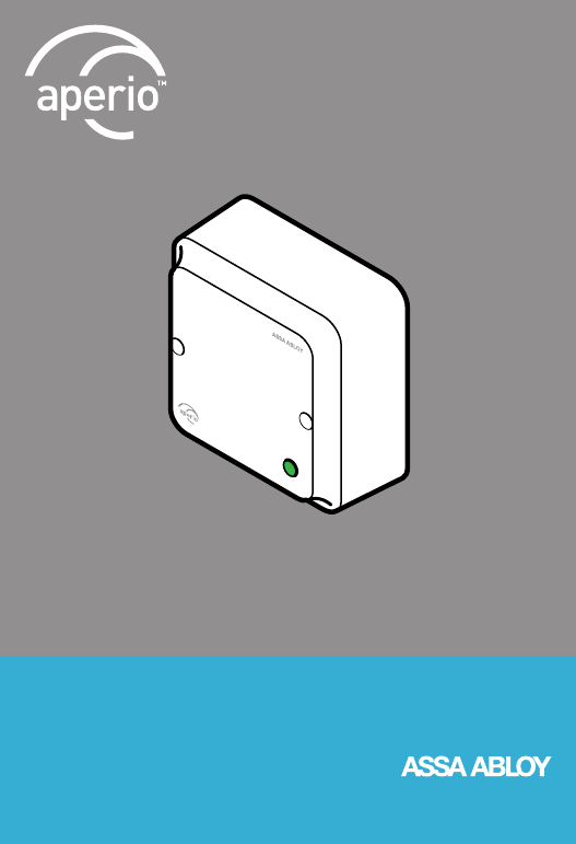
Aperio® Hub
AH40
Installation Instructions
2
AH40 - Table of Contents
AH40 - FCC and Industry Canada Statements 3
AH40 - Placement of Communication Hub 4
AH40 - Connectors 5
AH40 - Jumpers 6
AH40 - Communication Hub LED Indications 7
AH40 - Technical Data 8
ETL marking
Recognized component
Conforms to ANSI/UL standard 294, ANSI/UL 60950-1
Certified to CAN/CSA standard C22.2 No. 60950-1
4002570
For more detailed information about the Aperio system please read
ST-001279-Aperio Technology Installation Guide AH40.

3
AH40 - FCC and Industry Canada Statements
This equipment has been tested and found to comply with the limits for a Class B
digital device, pursuant to Part 15 of the FCC Rules. These limits are designed to provide
reasonable protection against harmful interference in a residential installation. This
equipment generates, uses and can radiate radio frequency
energy and, if not installed and used in accordance with the instructions, may cause
harmful interference to radio communications. However, there is no
guarantee that interference will not occur in a particular installation. If this equipment
does cause harmful interference to radio or television reception, which can be deter-
mined by turning the equipment off and on, the user is
encouraged to try to correct the interference by one of the following measures:
- Reorient or relocate the receiving antenna.
- Increase the separation between the equipment and receiver.
- Connect the equipment into an outlet on a circuit different from that to
which the receiver is connected.
- Consult the dealer or an experienced radio/TV technician for help.
This device complies with Part 15 of the FCC Rules and with RSS-210 of ISED. Operation
is subject to the following two conditions:
(1) This device may not cause harmful interference, and
(2) This device must accept any interference received, including interference that may
cause undesired operation.
Le présent appareil est conforme aux CNR d’ISED applicables aux
appareils radio exempts de licence. L’exploitation est autorisée aux deux
conditions suivantes:
1. l’appareil ne doit pas produire de brouillage, et
2. l’utilisateur de l’appareil doit accepter tout brouillage radioélectrique subi, même si
le brouillage est susceptible d’en compromettre le fonctionnement.
The term “IC:” before the equipment certification number only signifies that the Innova-
tion, Science and Economic Development Canada technical specifications were met.
Le terme “IC” devant le numéro de certification signifie seulement que les
spécifications techniques Innovation, Sciences et Développement économique Canada
ont été respectées.
FCC Caution: Any changes or modifications not expressly approved by the party respon-
sible for compliance could void the user’s authority to operate this equipment.
This radio transmitter (IC: 9504A-AH40R02) has been approved by ISED to
operate with the antenna types listed below with the maximum permissible gain
indicated.
Antenna types not included in this list, having a gain greater than the maximum
gain indicated for that type, are strictly prohibited for use with this device.
Antenna type: ASSA ABLOY AH-ANTENNA-1, max gain 2,15 dBi.
Le présent émetteur radio (IC: 9504A-AH40R02) a été approuvé par ISED
pour fonctionner avec les types d’antenne énumérés ci-dessous et ayant un gain
admissible maximal. Les types d’antenne non inclus dans cette liste, et dont le gain est
supérieur au gain maximal indiqué, sont strictement interdits pour l’exploitation de
l’émetteur. D’antenne énumérés: ASSA ABLOY AH-ANTENNA-1, Gain maximal indiqué
2,15 dBi.
4
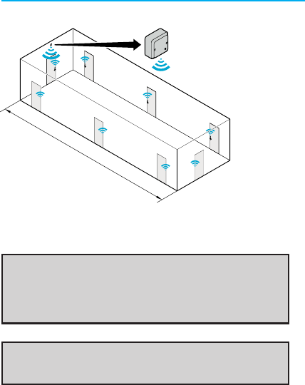
AH40 - Placement of Communication Hub
Example of placement of the Hub with 8 locks. AH40 can
manage up to 16 locks.
Note: AH40 Communication hub must be installed into a
junction box ex European 2-Gang, Aperio bottom cover or with
Americas adaptor plate to junction box. AH40 must be installed
by qualified and trained personal. Indoor installation only!
Note: The Aperio Communication hubs are not rated to be
installed in the plenum space.
< 15 m / ~ 50 ft
5
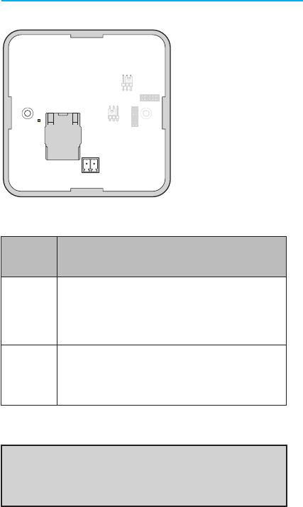
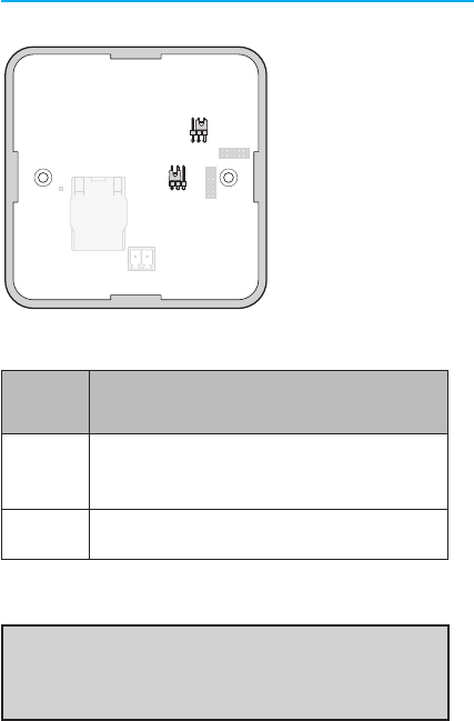
AH40 - Connectors
Note: When PoE (Power over Ethernet) is used, no power supply
should be connected to J321. The installation must comply with
national wiring regulations.
ConneCtors DesCription
J201
Ethernet connector. Connection to the Electronic Access
Control system through a 10BASE-T / 100BASE-TX Local
Area Network. Can also be used for power supply if
connected to a IEEE 802.3af compliant Power Sourcing
Device (PSE). Wire requirements CAT5 or higher.
J321
Power supply input, 8-24 VDC, 3.5 W. The power supply
shall be a Limited Power Source (LPS) according to EN
60950-1. The power supply shall be 3 A over current
protected. Wire requirements 16-22 AWG.
8-24V
- +
LINK PAIR
J201
J321
ANTENNA
EXT INT
6
Jumpers DesCription
ANTENNA Select external antenna by connecting the two left pins.
Select internal antenna by connecting the two right pins.
PAIR Select pairing mode by connecting the two left pins.
AH40 - Jumpers
Note: To install an external antenna use a thin screw driver and
gently bend the antenna cap loose. Be careful, there are sensitive
components behind the cap!
8-24V
- +
LINK PAIR
J201
J321
ANTENNA
EXT INT
7
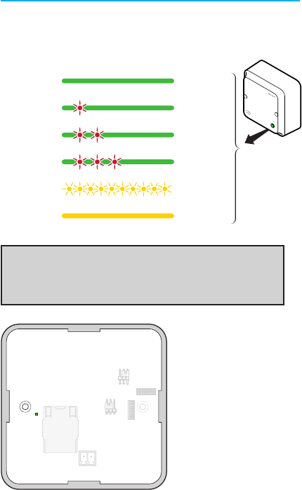
The Communication Hub has a status LED visible through the front
cover. It supports optical schemes with red, green and yellow. The
indication schemes are described by the figure below:
AH40 - Communication Hub LED Indications
Note: With the software tool Aperio® Programming Application
and an USB radio dongle, further system installation parameters
can be set.
The “LINK” LED on the
communication Hub
indicates both status of the
Ethernet Link level and if
communication is ongoing.
Note: LED on the Ethernet
connector is not used.
GreenOnline
Green + One
Red Flash
Aperio® Lock
Offline
Green + Two
Red Flashes
EAC Offline
Green + Three
Red Flashes
Aperio® Lock and
EAC Offline
Yellow + Off,
Fast Flash
UHF
Communication
YellowPairing Active
8-24V
- +
LINK PAIR
J201
J321
ANTENNA
EXT INT
8
Physical Dimensions 82 mm x 82 mm x 37 mm (H x W x T)
Power Supply 8-24 VDC or Power over Ethernet (PoE)
Power Rating
Power supply
The power supply shall be able to deliver minimum
3.5 W. The power supply shall be 3 A over current
protected.
PoE
IEEE 802.3af compliant class 1 Powered device (PD)
Ethernet 10BASE-T / 100BASE-TX Local Area Network
Radio Standard
IEEE 802.15.4 (2400 – 2483,5 MHz)
16 channels (11-26)
AES 128 bit encryption
Receiver Sensitivity -100 dBm
Wireless Transmit
Power
10 dBm/MHz according to EN ETSI 300 328.
Maximum spectral density.
Wireless Operating
Range
Indoors up to 15 m / ~ 50 ft depending upon
installed environment.
Internal Antenna Two port cross polarized patch antenna.
External Antenna
One reverse polarity SMA external antenna
connector. AH40 is certified and is only allowed
to be used with ASSA ABLOY external antenna AH
ANTENNA 1.
Operating
Temperature 5 °C to 35 °C
Humidity < 95 % non-condensing
IP Classification IP20
Safety and Emissions
FCC 47CFR Part 15 subpart B and subpart C
IC RSS-GEN issue 5
IC RSS-247 issue 2
EN ETSI 301 489-1 v2.1.1
EN ETSI 301 489-17 v3.1.1
EN ETSI 300 328 v2.1.1
EN 60950-1:2006/A11:2009/A1:2010/A12:2011/
A2:2013
UL 294-2010
C22.2
AH40 - Technical Data

9
NOTE

10
NOTE

11
NOTE

12
www.assaabloy.com/aperio
ASSA ABLOY, the global leader
in door opening solutions
D000732307-F-US