ASSALOY AHGUHF00 AH13 Communication Hub User Manual 10 0344 Exhibit Cover
ASSA ABLOY Inc. AH13 Communication Hub 10 0344 Exhibit Cover
UserManual.wiki
>
ASSALOY
>
AHGUHF00 User Manual
Manual
Navigation menu
Upload a User Manual
Namespaces
Wiki Guide
HTML
PDF
Info
Views
User Manual
Discussion / Help
Navigation
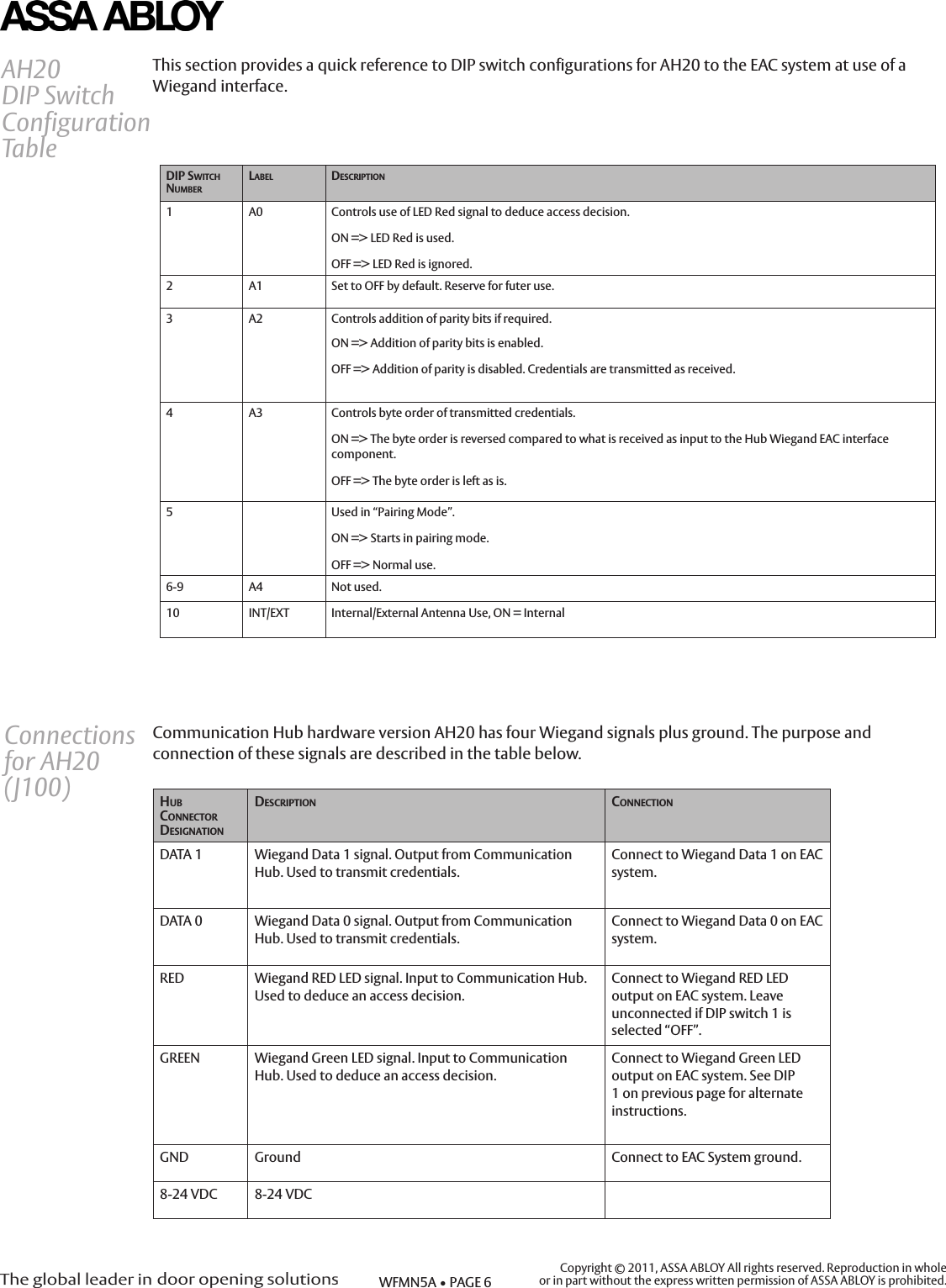
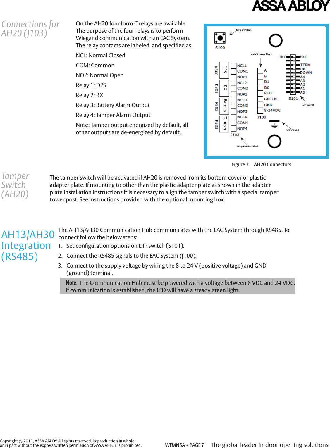
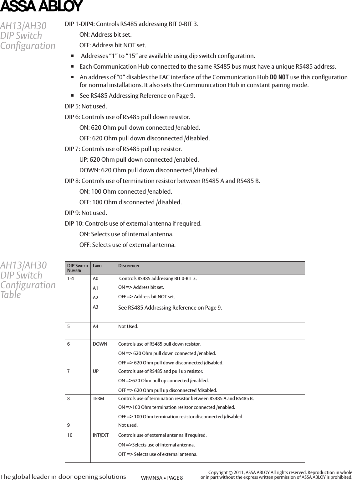
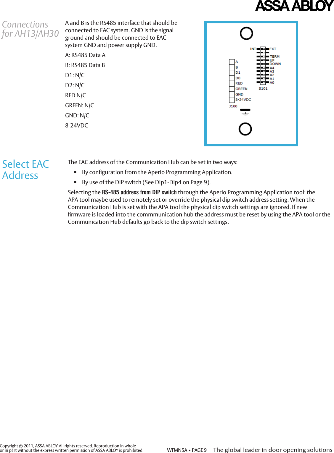
![Copyright © 2011, ASSA ABLOY All rights reserved. Reproduction in whole or in part without the express written permission of ASSA ABLOY is prohibited. WFMN5A • PAGE 51. Set configuration options on DIP switch (S101)2. Connect the Wiegand signals and dry contact outputs to the EAC System (J100 and J103)3. Connect to the supply voltage by wiring 8 to 24 V (positive voltage) and GND (ground). The AH20 Communication Hub communicates to the EAC System through Wiegand data and dry contacts. To connect follow these steps: AH20Integration(Wiegand) Note: The square box assembly requires a plaster ring to be secured to the box prior to securing the mounting plate to the assembly.Note: The Communication Hub must be powered with a voltage between 8 VDC and 24 VDC. If communication is established, the LED will have a steady green light.DIP 1: Controls use of RED LED signal to deduce Access Space Decisions. ON: RED LED signal input is used.OFF: RED LED signal input is ignored. If a signal is available that asserts access denied decision from EAC. ENABLE DIP 1 “ON” and attach signal to J100, RED. If EAC system does not have RED LED output, only GREEN or does not use LED outputs to assert access decisions, DIP 1 should be disabled “OFF”. Use lock relay output or similar EAC output (J100 GREEN) instead. Local override cards should not be used in conjunction with DIP 1 disabled (“OFF”) as this configuration may produce an access denied based on a time out. DIP 2: Reserved for future use. DIP 3: Controls addition of parity bits if required:ON: Addition of parity bits ENABLED.OFF: Addition of parity is DISABLED transmitted as received. When enabled, addition of one even parity bit (before) and one odd parity bit (after) is applied to the actual credential. Typically parity bits are already included in the creditial. In this case when DIP 3 is disabled (“OFF”) transmitted credential may include parity. DIP 4: Controls byte orders of transmitted credentials.ON: The byte order is reversed compared to what is received as input to the Hub Wiegand EAC interface component.OFF: The byte order is left as is. This setting is ignored as input to the hub in the case of the credential length does not make complete bytes The byte order received as input to the hub in the case of a 32 bit MIFARE UID credential is UID[3], UID[2], UID[1], UID[0]. This means that the byte order is already reversed earlier in the chain compared to the order specified in RFID interface standard ISO 14443-3.DIP 5: Used for “Pairing Mode”. ON: Pairing mode active.OFF: Normal use. When enabled/active the next time an unpaired lock attempts to pair, it will be paired with the hub. For unpairing the APA tool must be used. Reboot the hub for changes to take effect. DIP 6-9: Unused in AH-20DIP 10: Controls use of external antenna if required.ON: Selects use of internal antenna.OFF: Selects use of external antenna.AH20 DIP Switch ConfigurationDIP switches 1-9 in the “OFF” position on the Communication Hub yield a default Wiegand configuration that is compatible with most EAC systems. But better performance and increased functionality can result from a customized configuration.](https://usermanual.wiki/ASSALOY/AHGUHF00/User-Guide-1444158-Page-6.png)