ASSALOY AHGUHF00 AH13 Communication Hub User Manual 10 0344 Exhibit Cover
ASSA ABLOY Inc. AH13 Communication Hub 10 0344 Exhibit Cover
ASSALOY >
Manual

5015 B.U. Bowman Drive Buford, GA 30518 USA Voice: 770-831-8048 Fax: 770-831-8598
Certification Exhibit
FCC ID: U4A-AHGUHF00
IC: 6982A-AHGUHF00
FCC Rule Part: 15.247
IC Radio Standards Specification: RSS-210
ACS Report Number: 10-0344.W06.11.A
Manufacturer: Assa Abloy
Model: AH13
Manual

Aperio
Hub
Installation &
Integration
Instructions
WFMN5A
11MAR 2011
Copyright © 2011, ASSA ABLOY All rights reserved.
Reproduction in whole or in part without the express
written permission of ASSA ABLOY is prohibited.
EMEA Form: AAWL-260
01/31/11

Copyright © 2011, ASSA ABLOY All rights reserved. Reproduction in whole
or in part without the express written permission of ASSA ABLOY is prohibited.
WFMN5A • PAGE 2
CHAPTER 1: TECHNICAL SPECIFICATIONS ...............................................................................................................................3
CHAPTER 2: SYSTEM OVERVIEW .................................................................................................................................................3
Introduction .............................................................................................................................................................................3
System Description ..................................................................................................................................................3
The Aperio Programming Application ..................................................................................................................3
CHAPTER 3: INSTALL THE COMMUNICATION HUB ..............................................................................................................4
Instructions ..............................................................................................................................................................................4
AH20 Integration(Wiegand) ..............................................................................................................................................5
AH20 DIP Switch Configuration ............................................................................................................................5
AH20 DIP Switch Configuration Table ..................................................................................................................6
Connections for AH20 (J100) .................................................................................................................................6
Connections for AH20 (J103) .................................................................................................................................7
Tamper Switch (AH20) ............................................................................................................................................7
AH13/AH30 Integration (RS485) ......................................................................................................................................7
AH13/AH30 DIP Switch Configuration .................................................................................................................8
AH13/AH30 DIP Switch Configuration Table .......................................................................................................8
Connections for AH13/AH30 ..................................................................................................................................9
Select EAC Address ................................................................................................................................................................9
RS485 Bus Connection ......................................................................................................................................................10
Physical Hub Installation ..................................................................................................................................................11
Communication Hub Adapter Plate Insatllation ............................................................................................. 11
Hub LED Indication .............................................................................................................................................................12
Table of Contents
FCC Statement:
This equipment has been tested and found to comply with the limits for a Class B digital device, pursuant to Part
15 of the FCC Rules. These limits are designed to provide reasonable protection against harmful interference in a
residential installation. This equipment generates, uses, and can radiate radio frequency energy and, if not installed
and used in accordance with the instructions, may cause harmful interference to radio communications. However,
there is no guarantee that interference will not occur in a particular installation. If this equipment does cause
harmful Interference to radio or television reception, which can be determined by turning the equipment off and
on, the user is encouraged to try to correct the interference by one or more of the following measures:
• Reorient or relocate the receiving antenna.
• Increase the separation between the equipment and receiver.
• Connect the equipment into an outlet on a circuit different from that to which the receiver is Connected.
• Consult the dealer or an experienced radio/TV technician for help.”
Industry Canada:
This Class B digital apparatus meets all requirements of the Canadian Interference Causing Equipment Regulations.
Operation is subject to the following two conditions: (1) this device may not cause harmful interference, and (2)
this device must accept any interference received, including interference that may cause undesired operation.
Cet appareillage numérique de la classe B répond à toutes les exigences de l’interférence canadienne causant
des règlements d’équipement. L’opération est sujette aux deux conditions suivantes: (1) ce dispositif peut ne
pas causer l’interférence nocive, et (2) ce dispositif doit accepter n’importe quelle interférence reçue, y compris
l’interférence qui peut causer l’opération peu désirée.
Warnings:
Changes or modifications to this device not expressly approved by ASSA ABLOY could void the user’s authority to
operate the equipment.
“This equipment complies with FCC radiation exposure limits set forth for an uncontrolled environment. This
equipment should be installed and operated with minimum distance 20cm between the radiator and your body.
This transmitter must not be co-located or operating in conjunction with any other antenna or transmitter.”
Under Industry Canada regulations, this radio transmitter may only operate using an antenna of a type and
maximum (or lesser) gain approved for the transmitter by Industry Canada. To reduce potential radio interference
to other users, the antenna type and its gain should be so chosen that the equivalent isotropically radiated power
(e.i.r.p.) is not more than that necessary for successful communication.
Copyright © 2011, ASSA ABLOY All rights reserved. Reproduction in whole
or in part without the express written permission of ASSA ABLOY is prohibited. WFMN5A • PAGE 3
A PC, running on Windows
Vista, Windows XP or Windows
7 and USB2.0
Java runtime environment
version 6 or later
USB radio with the latest
firmware
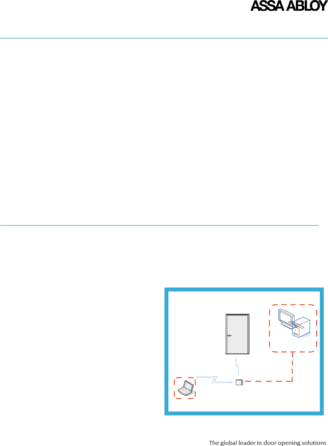
Chapter 2: System Overview
System
Description
When a user presents a supported credential to the lock the Aperio system is designed to send the
credential wirelessly to the Communication Hub. The Communication Hub (wired through RS-485 or
Wiegand) then communicates with an EAC (Electronic Access Control) system. The EAC system provides
the access decision to the Communication Hub ehere access to the lock is either granted or denied.
The Aperio
Programming
Application
Figure 1. EAC System
This manual supports installation personnel, project managers, and individuals with similar
responsibilities when installing and configuring Aperio technology version 2.3.0 and later.
Introduction
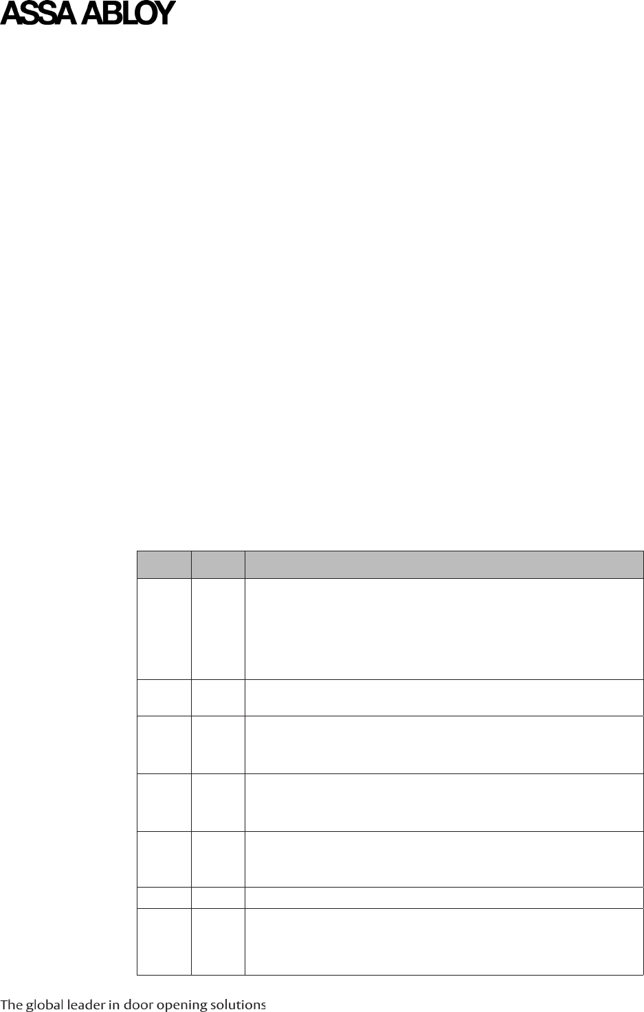
Chapter 1: Technical Specifications
Radio standard IEEE 802.15.4
Wireless Frequency Range
y2400 – 2483.5MHz 16 channels
(11-26)
y(11-25) US only
Receiver Sensitivity
-100dBm 20 % PER
Wireless Transmit Power 10dBm/MHz
Wireless Operating Range in office
environment
Indoors - up to 50 feet (15m)
Internal Antenna
Two cross polarized dipoles
IP Classification: IP20
Electronic Requirements
• Input Voltage: 8-24 VDC
• Current 250mA
External Antenna
yOne reverse polarity SMA external antenna connector.
AH20 or AH13/AH30 is certified to be used with external
antenna AH-ANTENNA-1. If other external antenna should
be used than AH-ANTENNA-1 from ASSA ABLOY, the
antenna should be of same type (dipole) and not have
larger antenna gain than 3.9dBi.
yIf coaxial cable need to be connected to AH20 or AH13/
AH30 plastic SMA extender AH-COAX-1 will be required to
tighten the coaxial cable SMA connector to AH20 or AH13/
AH30 SMA connector.
Operating Temperature
5°C to 35°C
Humidity
95% maximum (non-condensing)
Safety and Emissions
yFCC 47CFR Part 15 subpart B and subpart C
yIC RSS-210
yEN ETSI 301 489-17 v2.1.1
RS485/Wiegaurd
IEEE802.15.4 (2.4GHz)
EAC System
Aperio Communication Hub
Aperio Programming
Application
Lock
Copyright © 2011, ASSA ABLOY All rights reserved. Reproduction in whole
or in part without the express written permission of ASSA ABLOY is prohibited.
WFMN5A • PAGE 4
Chapter 3: Install the Communication Hub
Instructions
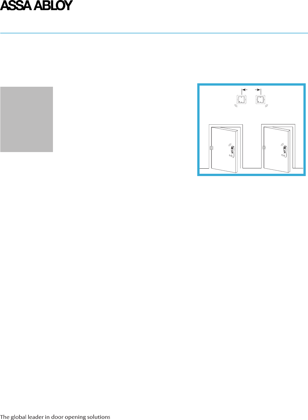
Placement
of the Hub
For a stable and reliable radio link it is recommended that the distance between the lock and the
Communication Hub is limited to 15 feet (5m). However, under good conditions (free air between the
units and limited radio interference from other transmitters) it is sometimes possible to increase the
distance to 35-45 feet (10-15m). Under poor conditions (heavy radio interface, etc.) it may be necessary
to keep the distance between the lock and the Communication Hub well below 15 feet (5m). There is no
minimum distance. If suitable, several Communication Hubs can be positioned together as long as the
Hub-to-Hub distance is 1 foot (.2m) or more.
Figure 2. Placement of Communication Hub
Typically, the LED on the Communication Hub cover should “point” to the lock.
The Communication Hub should be placed on the non-secure (key or card) side of the door.
Shorter distance and “light” materials in the walls permits placement on opposite sides.
Be aware of that metallic sheet or mesh will attenuate the radio signal. Inner ceiling is, for
example, sometimes covered with foil or metallic mesh.
Mirrors and larger metallic objects (like cable ladders) should kept at least 1 foot (2m) away
from lock or Communication Hub.
WiFi / WLAN routers and other radio transmitters operating in the 2.4 GHz band should be kept
at least 11-12 feet (3-5m) from the Communication Hub and lock.
Other possible sources of interference include microwave ovens, electric motors and other
high power electrical equipment. Keep at least 8-10 feet (2.5m) distance between the
Communication Hub and lock.
1’
Note:
Note: It is
recommended to
always verify the
radio link quality. To
do so see WFMN4A
Aperio Programming
Application
Instructions for more
information.

Copyright © 2011, ASSA ABLOY All rights reserved. Reproduction in whole
or in part without the express written permission of ASSA ABLOY is prohibited. WFMN5A • PAGE 5
1. Set configuration options on DIP switch (S101)
2. Connect the Wiegand signals and dry contact outputs to the EAC System (J100 and J103)
3. Connect to the supply voltage by wiring 8 to 24 V (positive voltage) and GND (ground).
The AH20 Communication Hub communicates to the EAC System through Wiegand data and dry
contacts. To connect follow these steps:
AH20
Integration
(Wiegand)
Note: The square box assembly
requires a plaster ring
to be secured
to the box prior to
securing the mounting plate to
the assembly.
Note:
The Communication Hub must be powered with a voltage between 8 VDC and 24 VDC.
If communication is established, the LED will have a steady green light.
DIP 1: Controls use of RED LED signal to deduce Access Space Decisions.
ON: RED LED signal input is used.
OFF: RED LED signal input is ignored.
If a signal is available that asserts access denied decision from EAC. ENABLE DIP 1 “ON” and attach
signal to J100, RED.
If EAC system does not have RED LED output, only GREEN or does not use LED outputs to assert access
decisions, DIP 1 should be disabled “OFF”. Use lock relay output or similar EAC output (J100 GREEN)
instead.
Local override cards should not be used in conjunction with DIP 1 disabled (“OFF”) as this
configuration may produce an access denied based on a time out.
DIP 2: Reserved for future use.
DIP 3: Controls addition of parity bits if required:
ON: Addition of parity bits ENABLED.
OFF: Addition of parity is DISABLED transmitted as received.
When enabled, addition of one even parity bit (before) and one odd parity bit (after) is applied to the
actual credential.
Typically parity bits are already included in the creditial. In this case when DIP 3 is disabled (“OFF”)
transmitted credential may include parity.
DIP 4: Controls byte orders of transmitted credentials.
ON: The byte order is reversed compared to what is received as input to the Hub Wiegand EAC
interface component.
OFF: The byte order is left as is.
This setting is ignored as input to the hub in the case of the credential length does not make
complete bytes
The byte order received as input to the hub in the case of a 32 bit MIFARE UID credential is UID[3], UID[2],
UID[1], UID[0]. This means that the byte order is already reversed earlier in the chain compared to the
order specified in RFID interface standard ISO 14443-3.
DIP 5: Used for “Pairing Mode”.
ON: Pairing mode active.
OFF: Normal use.
When enabled/active the next time an unpaired lock attempts to pair, it will be paired with the hub.
For unpairing the APA tool must be used. Reboot the hub for changes to take effect.
DIP 6-9: Unused in AH-20
DIP 10: Controls use of external antenna if required.
ON: Selects use of internal antenna.
OFF: Selects use of external antenna.
AH20 DIP
Switch
Configuration
DIP switches 1-9 in the “OFF” position on the Communication Hub yield a default Wiegand configuration
that is compatible with most EAC systems. But better performance and increased functionality can result
from a customized configuration.
Copyright © 2011, ASSA ABLOY All rights reserved. Reproduction in whole
or in part without the express written permission of ASSA ABLOY is prohibited.
WFMN5A • PAGE 6
This section provides a quick reference to DIP switch configurations for AH20 to the EAC system at use of a
Wiegand interface.
AH20
DIP Switch
Configuration
Table
DIP SwItch
Number
LabeL DeScrIPtIoN
1 A0 Controls use of LED Red signal to deduce access decision.
ON => LED Red is used.
OFF => LED Red is ignored.
2 A1 Set to OFF by default. Reserve for futer use.
3 A2 Controls addition of parity bits if required.
ON => Addition of parity bits is enabled.
OFF => Addition of parity is disabled. Credentials are transmitted as received.
4 A3 Controls byte order of transmitted credentials.
ON => The byte order is reversed compared to what is received as input to the Hub Wiegand EAC interface
component.
OFF => The byte order is left as is.
5 Used in “Pairing Mode”.
ON => Starts in pairing mode.
OFF => Normal use.
6-9 A4 Not used.
10 INT/EXT Internal/External Antenna Use, ON = Internal
hub
coNNector
DeSIgNatIoN
DeScrIPtIoN coNNectIoN
DATA 1 Wiegand Data 1 signal. Output from Communication
Hub. Used to transmit credentials.
Connect to Wiegand Data 1 on EAC
system.
DATA 0 Wiegand Data 0 signal. Output from Communication
Hub. Used to transmit credentials.
Connect to Wiegand Data 0 on EAC
system.
RED Wiegand RED LED signal. Input to Communication Hub.
Used to deduce an access decision.
Connect to Wiegand RED LED
output on EAC system. Leave
unconnected if DIP switch 1 is
selected “OFF”.
GREEN Wiegand Green LED signal. Input to Communication
Hub. Used to deduce an access decision.
Connect to Wiegand Green LED
output on EAC system. See DIP
1 on previous page for alternate
instructions.
GND Ground Connect to EAC System ground.
8-24 VDC 8-24 VDC
Connections
for AH20
(J100)
Communication Hub hardware version AH20 has four Wiegand signals plus ground. The purpose and
connection of these signals are described in the table below.
Copyright © 2011, ASSA ABLOY All rights reserved. Reproduction in whole
or in part without the express written permission of ASSA ABLOY is prohibited. WFMN5A • PAGE 7
On the AH20 four form C relays are available.
The purpose of the four relays is to perform
Wiegand communication with an EAC System.
The relay contacts are labeled and specified as:
NCL: Normal Closed
COM: Common
NOP: Normal Open
Relay 1: DPS
Relay 2: RX
Relay 3: Battery Alarm Output
Relay 4: Tamper Alarm Output
Note: Tamper output energized by default, all
other outputs are de-energized by default.
The tamper switch will be activated if AH20 is removed from its bottom cover or plastic
adapter plate. If mounting to other than the plastic adapter plate as shown in the adapter
plate installation instructions it is necessary to align the tamper switch with a special tamper
tower post. See instructions provided with the optional mounting box.
Tamper
Switch
(AH20)
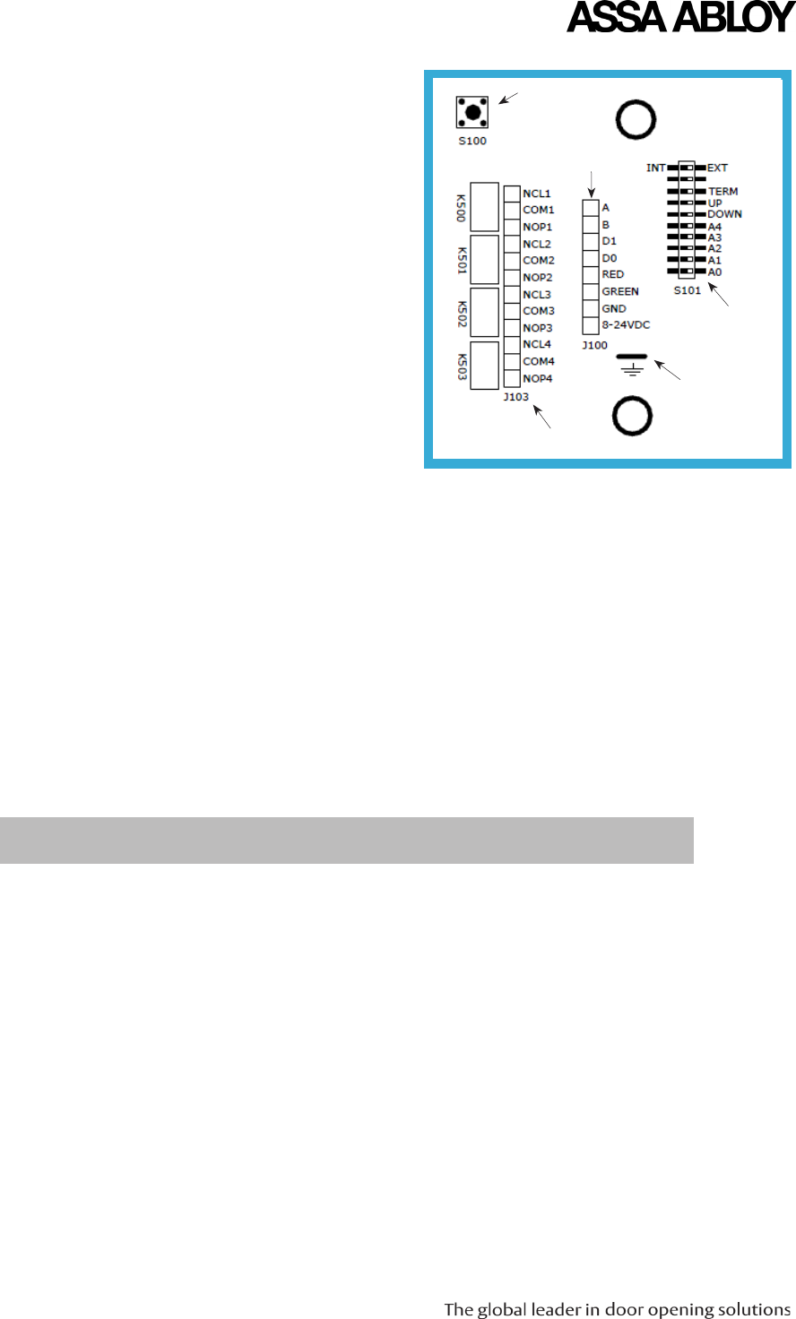
Relay Terminal Block
DIP Switch
Ground Lug
Tamper Switch
Main Terminal Block
DPS RX Battery Tamper
Figure 3. AH20 Connectors
Connections for
AH20 (J103)
AH13/AH30
Integration
(RS485)
1. Set configuration options on DIP switch (S101).
2. Connect the RS485 signals to the EAC System (J100).
3. Connect to the supply voltage by wiring the 8 to 24 V (positive voltage) and GND
(ground) terminal.
The AH13/AH30 Communication Hub communicates with the EAC System through RS485. To
connect follow the below steps:
Note:
The Communication Hub must be powered with a voltage between 8 VDC and 24 VDC.
If communication is established, the LED will have a steady green light.
Copyright © 2011, ASSA ABLOY All rights reserved. Reproduction in whole
or in part without the express written permission of ASSA ABLOY is prohibited.
WFMN5A • PAGE 8
DIP 1-DIP4: Controls RS485 addressing BIT 0-BIT 3.
ON: Address bit set.
OFF: Address bit NOT set.
Addresses “1” to “15” are available using dip switch configuration.
Each Communication Hub connected to the same RS485 bus must have a unique RS485 address.
An address of “0” disables the EAC interface of the Communication Hub DO NOT use this configuration
for normal installations. It also sets the Communication Hub in constant pairing mode.
See RS485 Addressing Reference on Page 9.
DIP 5: Not used.
DIP 6: Controls use of RS485 pull down resistor.
ON: 620 Ohm pull down connected /enabled.
OFF: 620 Ohm pull down disconnected /disabled.
DIP 7: Controls use of RS485 pull up resistor.
UP: 620 Ohm pull down connected /enabled.
DOWN: 620 Ohm pull down disconnected /disabled.
DIP 8: Controls use of termination resistor between RS485 A and RS485 B.
ON: 100 Ohm connected /enabled.
OFF: 100 Ohm disconnected /disabled.
DIP 9: Not used.
DIP 10: Controls use of external antenna if required.
ON: Selects use of internal antenna.
OFF: Selects use of external antenna.
AH13/AH30
DIP Switch
Configuration
AH13/AH30
DIP Switch
Configuration
Table
DIP SwItch
Number
LabeL DeScrIPtIoN
1-4 A0
A1
A2
A3
Controls RS485 addressing BIT 0-BIT 3.
ON => Address bit set.
OFF => Address bit NOT set.
See RS485 Addressing Reference on Page 9.
5 A4 Not Used.
6 DOWN Controls use of RS485 pull down resistor.
ON => 620 Ohm pull down connected /enabled.
OFF => 620 Ohm pull down disconnected /disabled.
7 UP Controls use of RS485 and pull up resistor.
ON =>620 Ohm pull up connected /enabled.
OFF => 620 Ohm pull up disconnected /disabled.
8 TERM Controls use of termination resistor between RS485 A and RS485 B.
ON =>100 Ohm termination resistor connected /enabled.
OFF => 100 Ohm termination resistor disconnected /disabled.
9 Not used.
10 INT/EXT Controls use of external antenna if required.
ON =>Selects use of internal antenna.
OFF => Selects use of external antenna.
Copyright © 2011, ASSA ABLOY All rights reserved. Reproduction in whole
or in part without the express written permission of ASSA ABLOY is prohibited. WFMN5A • PAGE 9
A and B is the RS485 interface that should be
connected to EAC system. GND is the signal
ground and should be connected to EAC
system GND and power supply GND.
A: RS485 Data A
B: RS485 Data B
D1: N/C
D2: N/C
RED N/C
GREEN: N/C
GND: N/C
8-24VDC
Connections
for AH13/AH30
Select EAC
Address
The EAC address of the Communication Hub can be set in two ways:
By configuration from the Aperio Programming Application.
By use of the DIP switch (See Dip1-Dip4 on Page 9).
Selecting the RS-485 address from DIP switch through the Aperio Programming Application tool: the
APA tool maybe used to remotely set or override the physical dip switch address setting. When the
Communication Hub is set with the APA tool the physical dip switch settings are ignored. If new
firmware is loaded into the commmunication hub the address must be reset by using the APA tool or the
Communication Hub defaults go back to the dip switch settings.
Copyright © 2011, ASSA ABLOY All rights reserved. Reproduction in whole
or in part without the express written permission of ASSA ABLOY is prohibited.
WFMN5A • PAGE 10
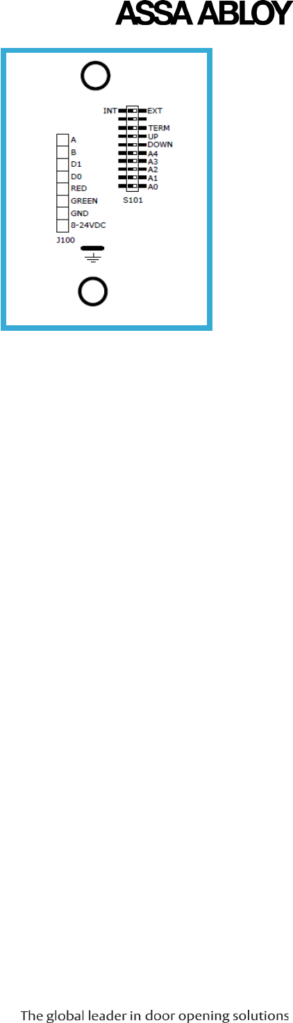
The RS-485 bus consists of a twisted-pair cable with a characteristic impedance of between 90 Ohm
and 120 Ohms. Maximum bus length is1000m. Depending on the EAC system, a maximum of 16 units,
including the EAC system, can be connected to the same bus.
If there is more than one Communication Hub to connect, the hubs should be connected in a daisy
chain, not as a star so that all RS485 A connectors are connected together and all RS485 B connectors
are connected together on the RS-485 bus (Fig. 5). Both ends of the RS-485 bus must be terminated.
To terminate a Communication Hub at the end of the bus, switch 8 of the DIP switch must be in the ON
position. All other Communication Hubs in the chain must have switch 8 of the DIP switch set to the OFF
position. Refer to the EAC documentation for proper termination of the bus on the EAC side.
Pull up and pull down-resistors should be enabled once bus. Refer to EAC documentation for use of
pull up or pull down on the EAC side. If pull up and pull down from the EAC system is not used, one
Communication Hub on the bus should have DIP switches 6 and 7 set to the ON position.
Two examples of connection of multiple Communication Hubs to a single RS-485 bus of an EAC system:
RS485 Bus
Connection
EAC System
Hub 1 Hub 2 Hub N
End of Bus
Termination
Enabled DIP 6 OFF
DIP 7 OFF
DIP 8 OFF
DIP 6 OFF
DIP 7 OFF
DIP 8 OFF
DIP 6 ON
DIP 7 ON
DIP 8 ON
A
B
A B A B A B
DIP 6 ON
DIP 7 ON
DIP 8 ON
Termination
disabled DIP 6 OFF
DIP 7 OFF
DIP 8 ON
Hub 1 Hub 2
A B A B
EAC System
Figure 4. Examples, Communication Hub Connections
aDDreSSeS a0 a1 a2 a3
0 ON
1 ON
2 ON ON
3 ON
4 ON
5 ON ON
6 ON ON
7 ON ON ON
8 ON
9 ON ON
10 ON ON
11 ON ON ON
12 ON ON
13 ON ON ON
14 ON ON ON
15 ON ON ON ON
Figure 5. Address Examples
Copyright © 2011, ASSA ABLOY All rights reserved. Reproduction in whole
or in part without the express written permission of ASSA ABLOY is prohibited. WFMN5A • PAGE 11
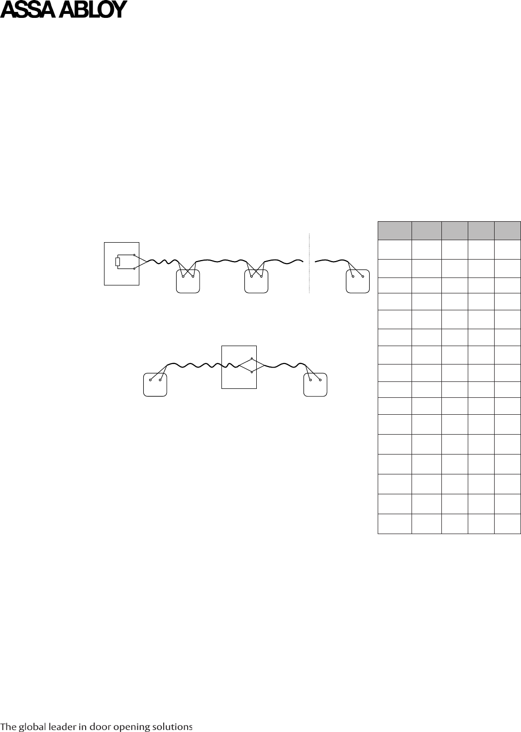
1. Remove the plugs from the interior of the mounting plate.
2. Secure the Communication Hub to the box with two screws.
3. Place the plugs in the through holes of the mounting plate.
4. Place the Communication Hub on top of the adapter plate.
5. Insert two screws in the through holes of the Communication Hub.
Communication
Hub
Adapter Plate
Installation
Physical Hub
Installation
Square Box Assembly Octagon Box Assembly
Switch Box Assembly Handy Box Assembly
plaster ring
mounting plate
plugs
screws
Communication Hub screws
box
Figure 6. Communication Hub Assembly
Note:
Complete all Wiegand and DIP switch configuration prior to installing the
Communication Hub.
To install the Communication Hub, follow the following steps:
Note:
The square box assembly requires a plaster ring
to be secured to the box prior to
securing the mounting plate to the assembly.
Copyright © 2011, ASSA ABLOY All rights reserved. Reproduction in whole
or in part without the express written permission of ASSA ABLOY is prohibited.
WFMN5A • PAGE 12
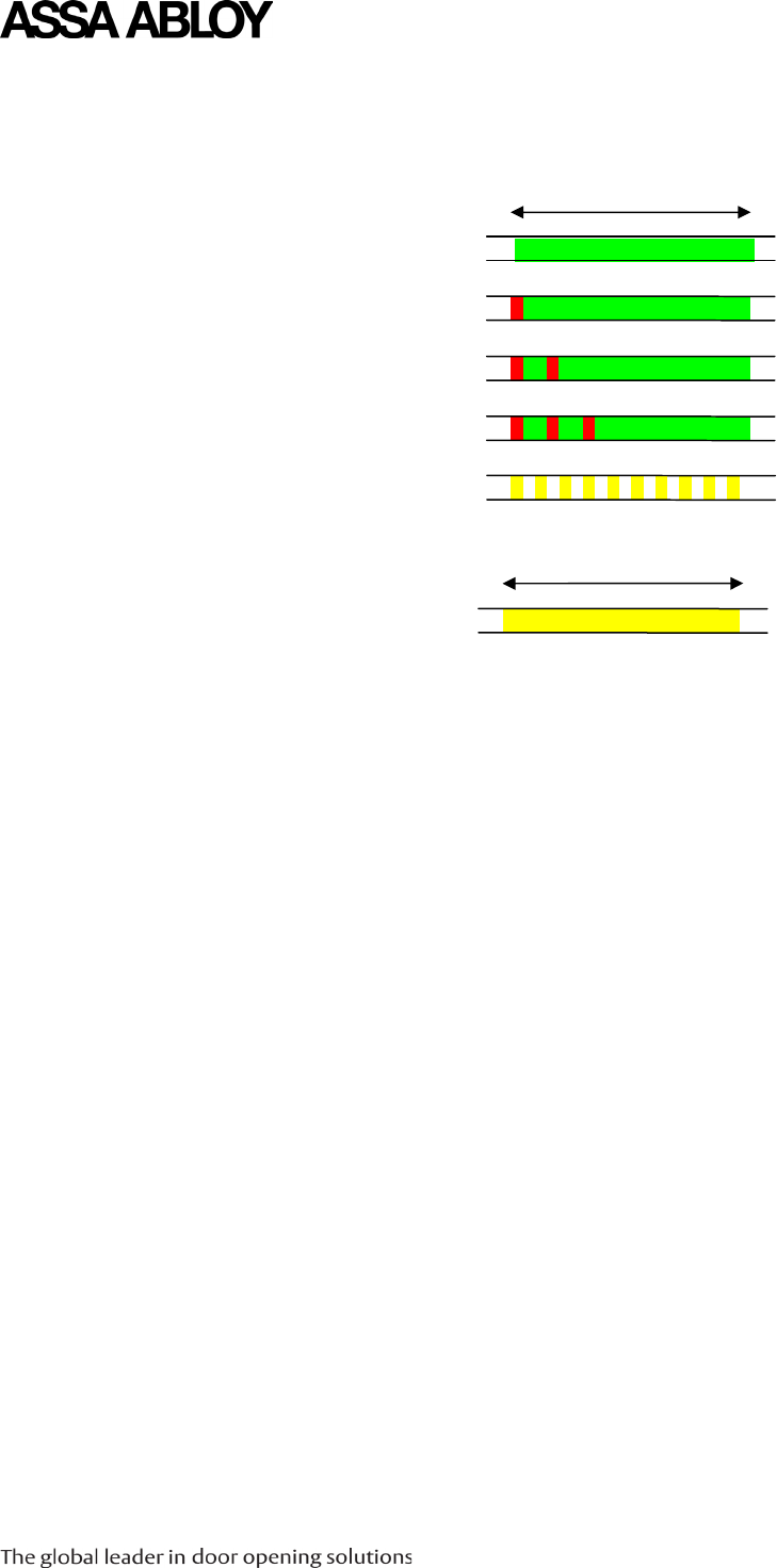
Hub LED
Indications
Online
Aperio Lock Offline
EAC Offline
Aperio Lock and EAC Offline
UHF Communication
Green
Green + One Red Flash
Green + Two Red Flashes
Green + Three Red Flashes
Yellow + Off, Fast Flash
Pairing Active Yellow
Figure 7. Communication Hub Normal LED Indications
Figure 8. Communication Hub Normal LED Indications
The Communication Hub has a single LED that supports an optical scheme with red, green and yellow.
The indication scheme is described by the two figures below:

Notes

ASSA ABLOY is the
global leader in door
opening solutions,
dedicated to satisfying
end user needs for
security, safety and
convenience WFMN5A • 01/11