ASSALOY PRXTRMH1 PROXIMITY CARD READER User Manual Appendix D Schematics
ASSA ABLOY Inc. PROXIMITY CARD READER Appendix D Schematics
UserManual.wiki
>
ASSALOY
>
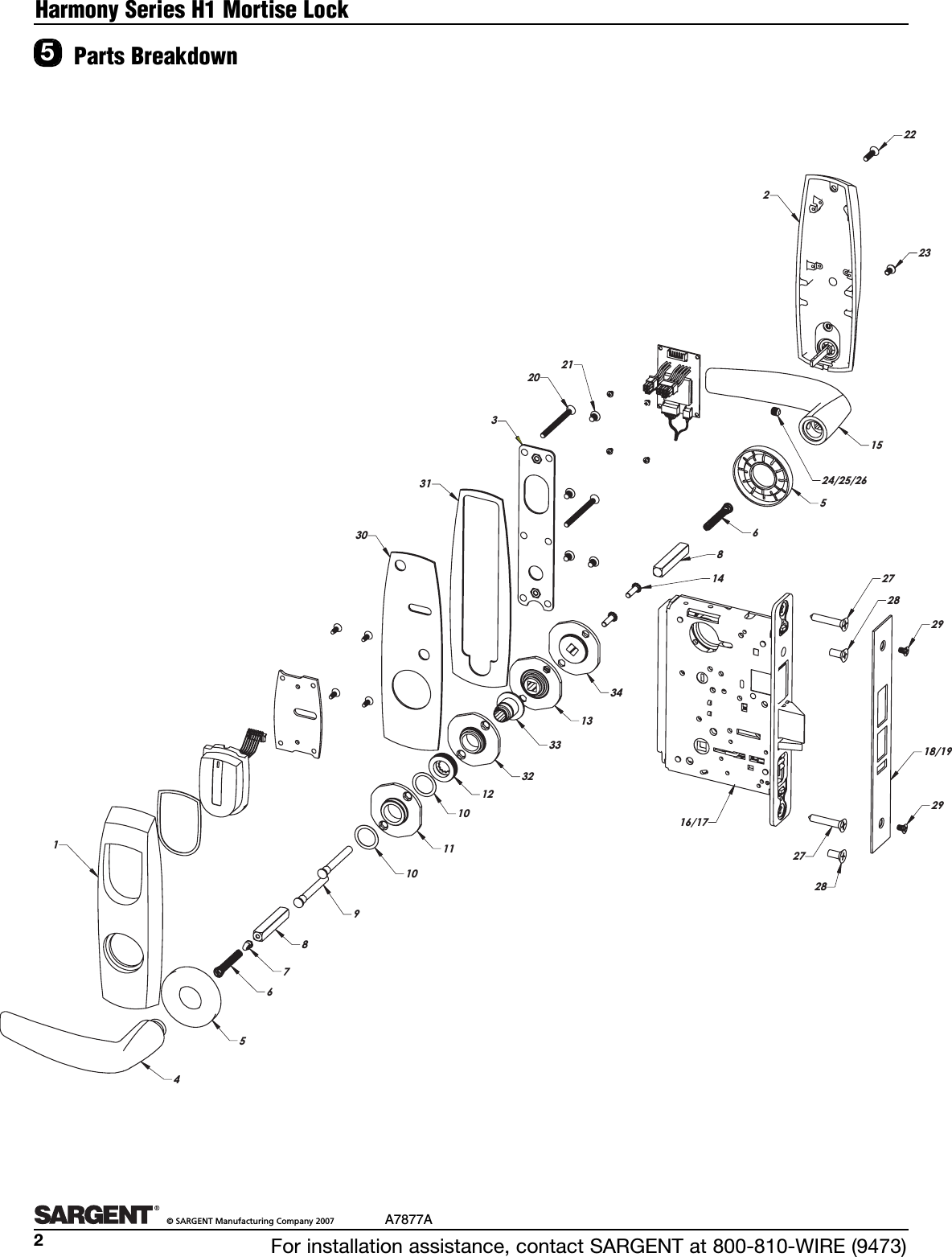
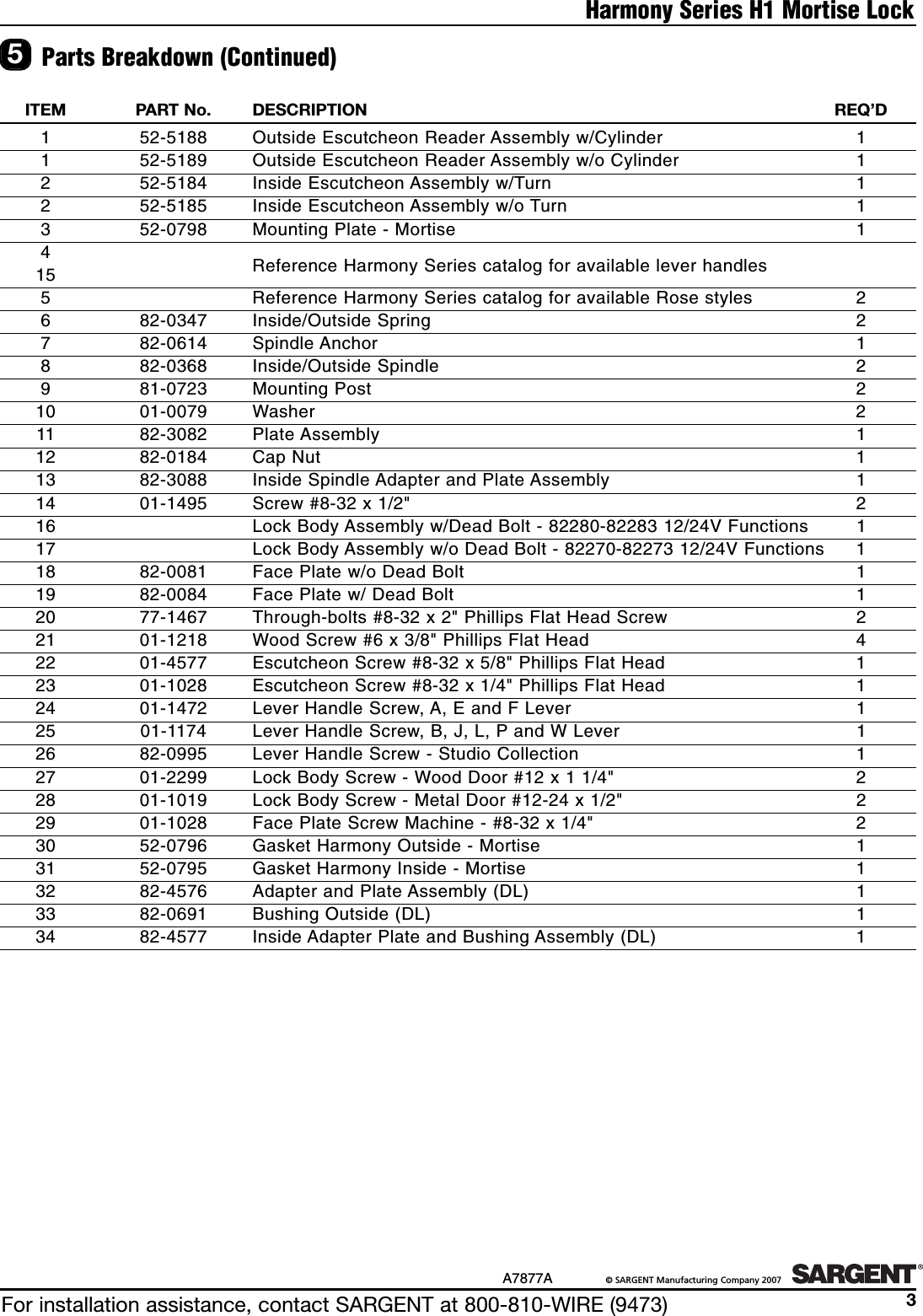
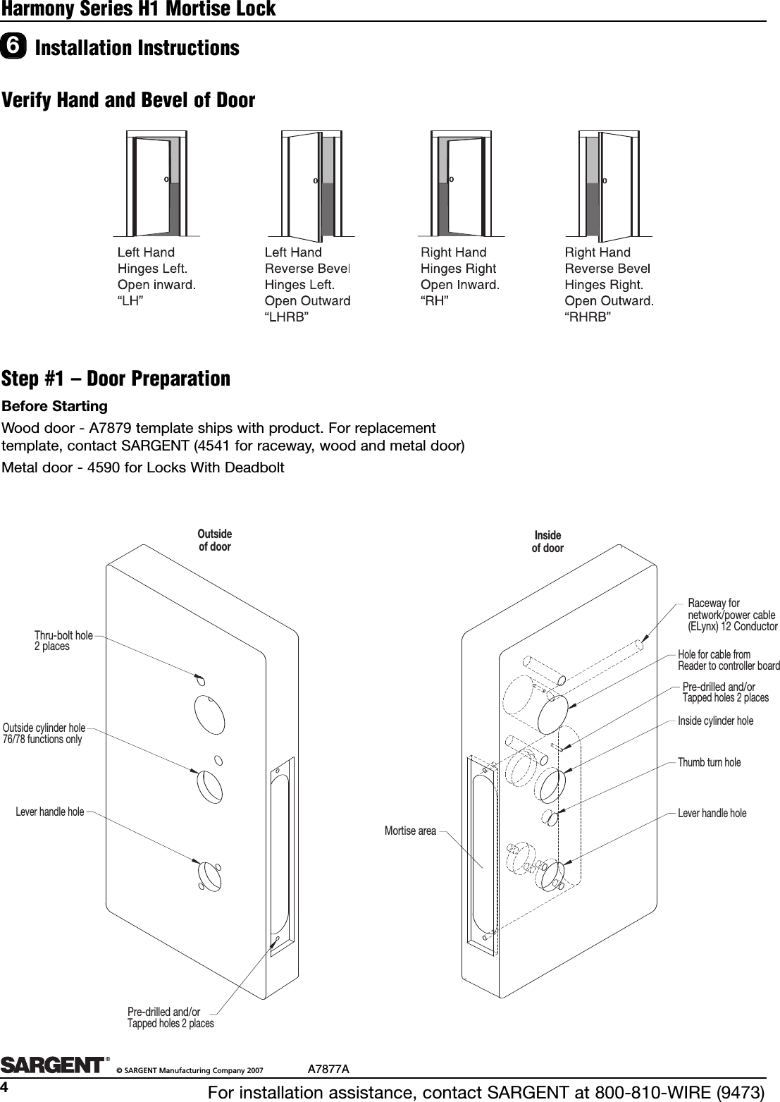
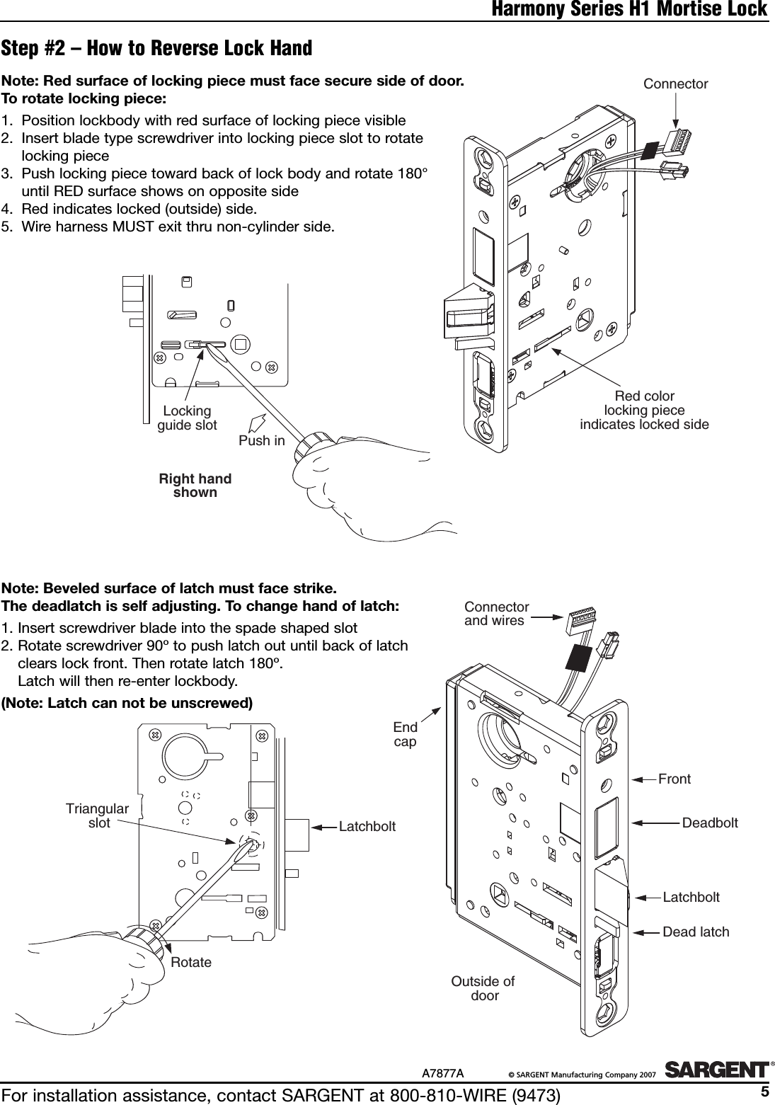
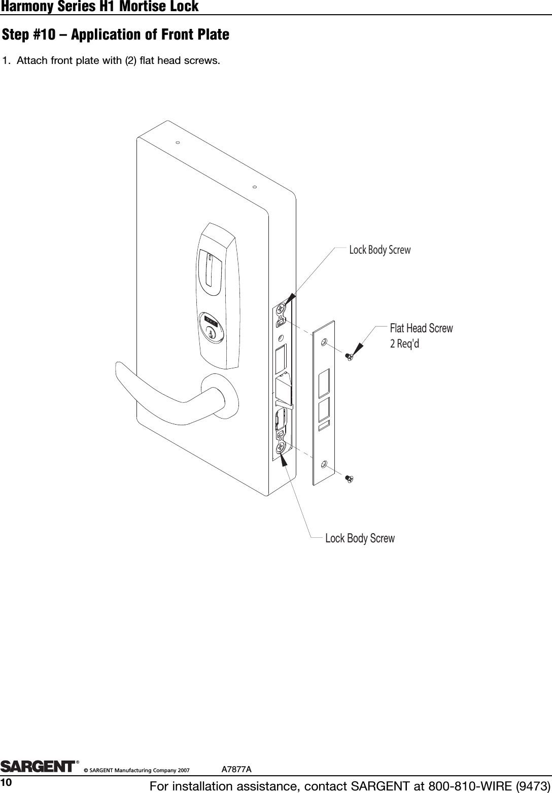
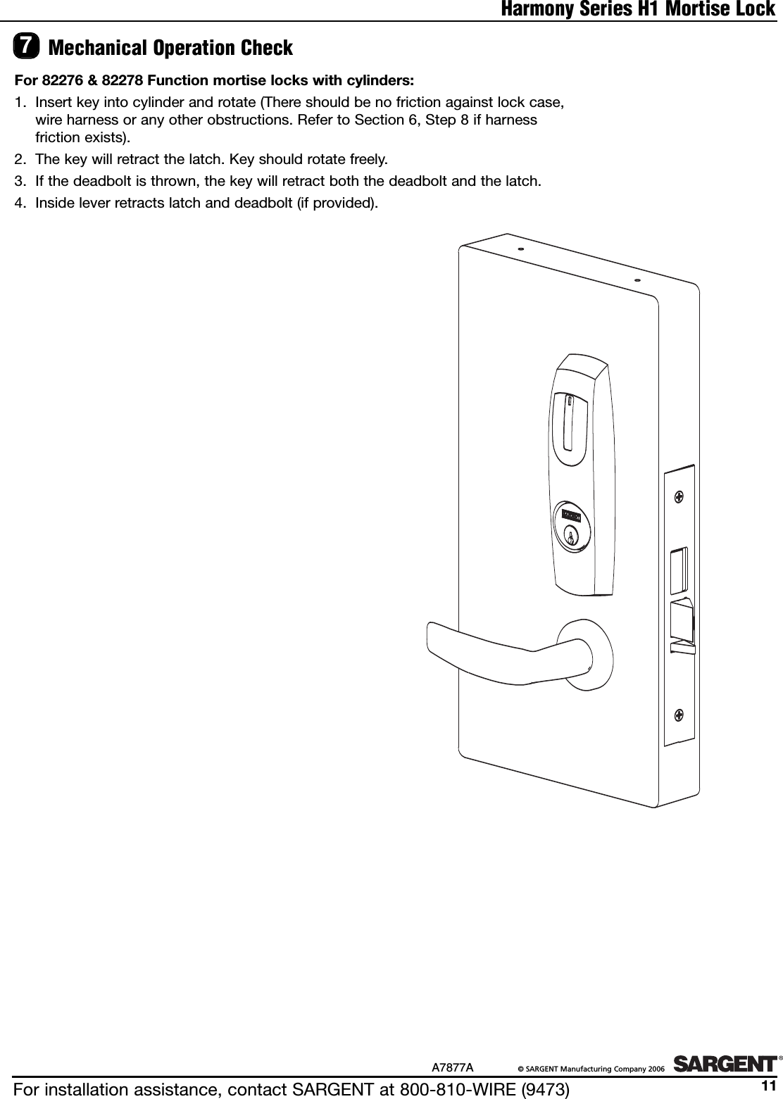
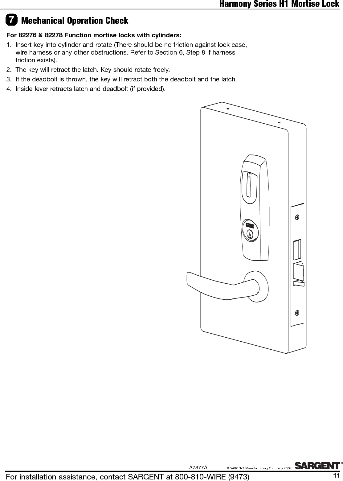
PRXTRMH1 User Manual
USERS MANUAL
Navigation menu
Upload a User Manual
Namespaces
Wiki Guide
HTML
PDF
Info
Views
User Manual
Discussion / Help
Navigation