ASSALOY SCYICLS0 S-Series iClass Lock User Manual FCC Part 15
ASSA ABLOY Inc. S-Series iClass Lock FCC Part 15
ASSALOY >
Contents
- 1. Manual - S1 Series
- 2. Manual - S2 Series
- 3. Manual
Manual - S2 Series

5015 B.U. Bowman Drive Buford, GA 30518 USA Voice: 770-831-8048 Fax: 770-831-8598
Certification Exhibit
FCC ID: U4A-SCYICLS0
IC: 6982A-SCYICLS0
FCC Rule Part: 15.225
IC Radio Standards Specification: RSS-210
ACS Report Number: 10-0199.W06.11.A
Manufacturer: Assa Abloy, Inc.
Model: S1-IA/IK, S2-IA/IK
Manual
Model S2-IA/IK
A7786E
10/10
Copyright 2010, Sargent Manufacturing Company, an ASSA ABLOY Group company.
All rights reserved. Reproduction in whole or in part without the express written
permission of Sargent Manufacturing Company is prohibited.
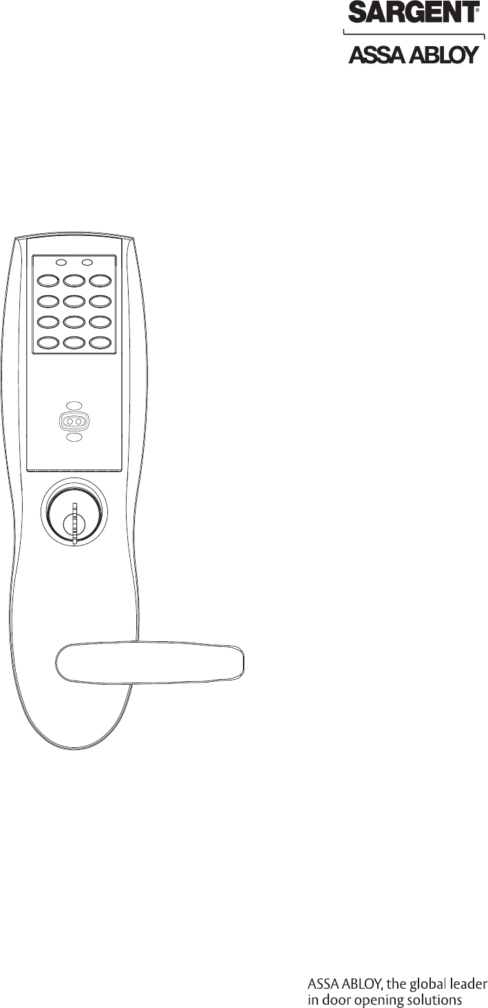
Installation Instructions
Profile Series v.S2 WiFi
Mortise Lock
1-800-810-WIRE • www.sargentlock.com • A7786E
Copyright © 2010, Sargent Manufacturing Company, an ASSA ABLOY Group company. All rights reserved.
Reproductions in whole or in part without express written permission of Sargent Manufacturing Company is prohibited.
10/15/10
Warning: Changes or modifications to this unit not expressly approved by the party
responsible for compliance could void the user’s authority to operate the equipment.
Warning
1
1
2
3
4
5
6
7
Table of Contents
Warning ...................................................................................2
General Description .................................................................3
Hardware Specifications .........................................................3
Electronic Specifications .........................................................3
Installation Wiring Overview ...................................................3
Lock Wiring ..............................................................................4
Parts Breakdown .....................................................................5
Installation Instructions ..........................................................7
Operational Check ................................................................15
8
9
FCC:
NOTE: This equipment has been tested and found to comply with the limits for a Class B digital device, pursuant to
Part 15 of the FCC Rules. These limits are designed to provide reasonable protection against harmful interference in
a residential installation.
This equipment generates, uses, and can radiate radio frequency energy and, if not installed and used in accordance
with the instructions, may cause harmful interference to radio communications. However, there is no guarantee that
interference will not occur in a particular installation. If this equipment does cause harmful interference to radio or
television reception, which can be determined by turning the equipment off and on, the user is encouraged to try to
correct the interference by one or more of the following measures:
• Reorient or relocate the receiving antenna.
• Increase the separation between the equipment and receiver.
• Connect the equipment into an outlet on a circuit different from that to which the receiver is connected.
• Consult the dealer or an experienced radio/TV technician for help.
Industry Canada:
Statement: The term “IC:” before the radio certification number only signifies that Industry Canada technical specifi-
cations were met.
This Class B digital apparatus meets all requirements of the Canadian Interference Causing Equipment Regulations.
Operation is subject to the following two conditions: (1) this device may not cause harmful interference, and (2) this
device must accept any interference received, including interference that may cause undesired operation.
Cet appareillage numérique de la classe B répond à toutes les exigences de l’interférence canadienne causant des
règlements d’équipement. L’opération est sujette aux deux conditions suivantes: (1) ce dispositif peut ne pas causer
l’interférence nocive, et (2) ce dispositif doit accepter n’importe quelle interférence reçue, y compris l’interférence qui
peut causer l’opération peu désirée.
To comply with “Fire Listed” doors, the batteries must be replaced with alkaline batteries only.
SARGENT Mfg. Co. v.S Series locksets utilizing a door position switch (DPS) are not rated for,
or intended for use in life safety applications.
!
10/15/10
1-800-810-WIRE • www.sargentlock.com • A7786E 3
Copyright © 2010, Sargent Manufacturing Company, an ASSA ABLOY Group company. All rights reserved.
Reproductions in whole or in part without express written permission of Sargent Manufacturing Company is prohibited.
Profile Series v.S2 WiFi Mortise Lock
Hardware Specifications
General Description
The SARGENT Profile Series v.S2 mortise lock is available with either a Prox 125 kHz or an HID iCLASS®
13.56 MHz technology reader. It is designed for applications requiring wireless access control.
The v.S2 is a self-contained microprocessor-controlled access control product with non-volatile memory.
It is able to utilize the existing wireless LAN (802.11b/g) in order to communicate with the access control
system. The v.S2 lock holds a total of 2000 different user codes.
This product is operated by six (6) “AA” alkaline batteries or a SARGENT 3267 9VDC power supply. SARGENT
mortise locks are designed with quality components to provide high security, performance and durability.
The Profile Series v.S2 mortise lock may be used for both indoor and outdoor applications. A weather-
protective gasket is recommended for outdoor applications (Provided with unit).
HID® and iCLASS® are registered trademarks of HID Global Corporation.
Electronic Specifications
• Wireless (WiFi 802.11 b/g) online, battery-operated
• 2000 Users per lock (more possible with software)
• 10,000 Event audit trail
• Centralized lock management
• Door Status Monitoring*
• Easy installation (no need to hardwire)
3
4
2
• Latch: One-piece stainless steel, 3⁄4" projection
• Deadbolt: One-piece hardened stainless steel
• Guardbolt: Stainless steel, non-handed
• Handed: Easily field reversible without
opening case
• Case: 12-gauge, heavy duty wrought steel
• UL Listed (3 hours)
• Input Power: DC 9V, 1.5A (6 AA alkaline batteries
or optional hard-powered)
• Lockdown capable*
• HID iCLASS (13.56 MHz) and 125 kHz prox (proxim-
ity) compatible (26-39 bit formats)
• AWE Prefix available for WPA2, PEAP and EAP-TS
Wireless Encryption Support
• Outside lever for iCLASS controlled by any 13.56
MHz iCLASS credential
• Outside lever for 125 kHz prox controlled by
any combination of keypad, prox reader, or
mechanical cylinder
• Inside lever retracts latch and deadbolt
• Locks furnished for 1-3/4" doors. Can be
furnished for other door sizes upon request.
Consult factory.
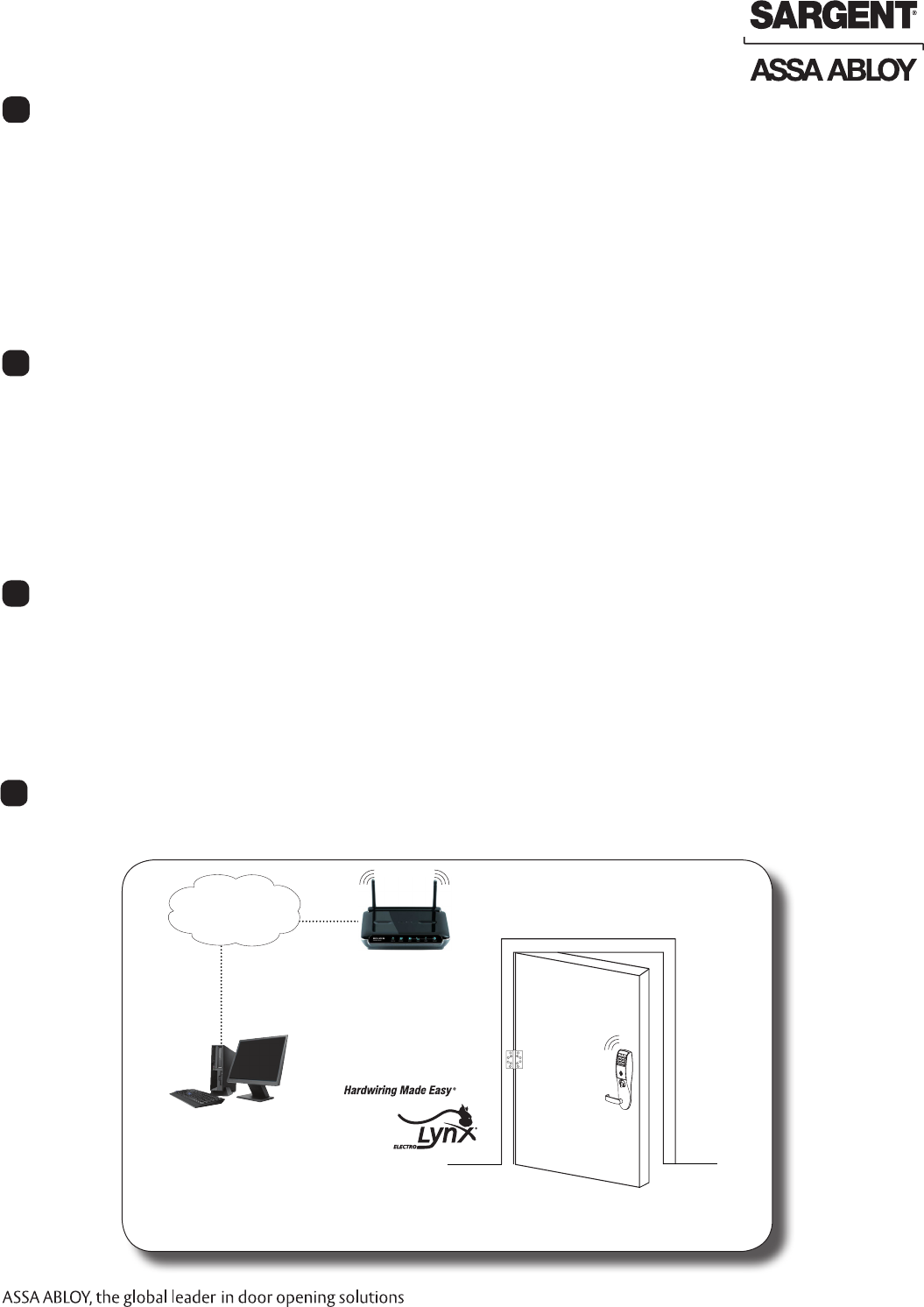
SARGENT Profile Series WIFI v.S2 Typical Application
802.11b/g Wireless Network Device
Lock Management
Tool (LMT)
v.S2 Lock
Internal
Building
Network (Intranet)
Network
Interface
Card
Ethernet LAN
* Lockdown and real-time door status monitoring available
only when lock is hard-powered
Installation Wiring Overview
5
4 1-800-810-WIRE • www.sargentlock.com • A7786E
Copyright © 2010, Sargent Manufacturing Company, an ASSA ABLOY Group company. All rights reserved.
Reproductions in whole or in part without express written permission of Sargent Manufacturing Company is prohibited.
10/15/10
Profile Series v.S2 WiFi Mortise Lock
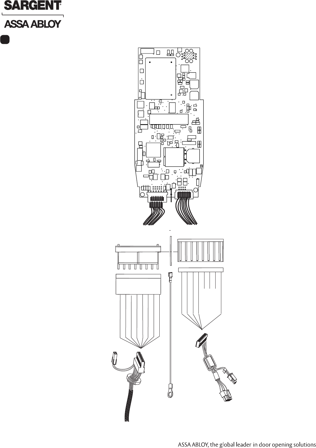
Lock Wiring
6
DX NC (GREEN/WHITE)
RX COM (WHITE)
RX NC (GREEN)
DX (WHITE/BLACK)
LX NO (RED/YELLOW)
LX COM (RED/GREEN
Motor B (BLACK)
Motor A (RED)
TB1
E1 TB2
8
7
6
5
4
3
2
1
1
2
3
4
5
6
7
8
From
Lock Body
(+) 9VDC (RED)
(-) (BLACK)
AX/DPS NC (PINK)
AX/DPS COM (VIOLET)
Unused
Unused
Unused
EGND (GREEN)
DPS
Power
Ring Terminal
From Trim
Controller Board Connectors
(Inside Escutcheon)
DPS
10/15/10
1-800-810-WIRE • www.sargentlock.com • A7786E 5
Copyright © 2010, Sargent Manufacturing Company, an ASSA ABLOY Group company. All rights reserved.
Reproductions in whole or in part without express written permission of Sargent Manufacturing Company is prohibited.
Profile Series v.S2 WiFi Mortise Lock
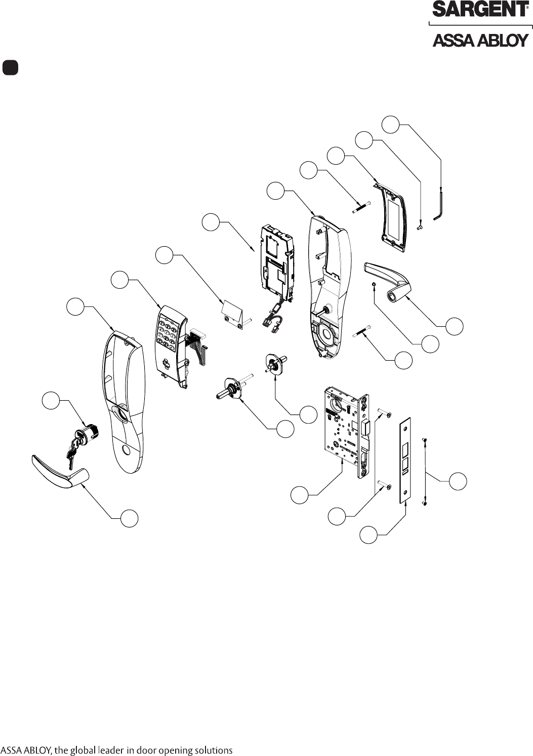
Parts Breakdown 125 kHz Prox and 13.56 MHz iCLASS
7
5
7
4
8
9
9
9
16
3
7
9
2
10
9
1
12
11
13
15
14
15
6
6 1-800-810-WIRE • www.sargentlock.com • A7786E
Copyright © 2010, Sargent Manufacturing Company, an ASSA ABLOY Group company. All rights reserved.
Reproductions in whole or in part without express written permission of Sargent Manufacturing Company is prohibited.
10/15/10
Profile Series v.S2 WiFi Mortise Lock
1 Outside Lever Reference 8200 Catalog for available levers 1
2 Inside Lever Reference 8200 Catalog for available levers 1
3 82-0493 O/S Escutcheon only with Cylinder 1
82-0495 O/S Escutcheon only without Cylinder
4 82-0492 Inside Escutcheon only without Thumb Turn 1
82-4571 Inside Escutcheon only with Thumb Turn 1
5
52-2431 125 kHz Prox Only Assembly (PA)
1
52-2432 Keypad and 125 kHz Prox Assembly (PK)
OR
52-4255 13.56 MHz Prox Only Assembly (IA)
52-4256 Keypad and 13.56 MHz Prox Assembly (IK)
6 52-4200 S2 Controller Assembly (Double Pulse) 1
52-4265 S2 AWE Controller Assembly Kit
7 52-3855 Battery Cover Assembly 1
8 01-1212 Security Screw 1
9 52-2427 Profile Screw Pack - Specify Finish (Includes: Fire Stop Plate,
Trim Mounting Screws, Security Allen Wrench)
1
10 Consult Factory Lever Handle Screw (Depends on Lever Style) 1
11 Consult Factory Inside Adapter Assembly (Depends on Lever Style) 1
12 Consult Factory Outside Adapter Assembly (Depends On Lever Style) 1
13 S2-82276-hand-finish Lockbody with Deadbolt with Cylinder 1
S2-82277-hand-finish Lockbody with Deadbolt without Cylinder
S2-82278-hand-finish Lockbody without Deadbolt with Cylinder
S2-82279-hand-finish Lockbody without Deadbolt without Cylinder
14 82-0084 Faceplate with Deadbolt (shown) 1
82-0081 Faceplate without deadbolt 1
15 77-4336 Mortise Screw Pack - Specify Finish (Includes: Wood and Me-
tal Lock body Screws, Faceplate Screws, and Strike Screws)
1
16 Consult Factory #43 Mortise Cylinder 1
ITEM PART NO. DESCRIPTION QTY.
Parts Breakdown 125 kHz Prox and 13.56 MHz iCLASS, continued
10/15/10
1-800-810-WIRE • www.sargentlock.com • A7786E 7
Copyright © 2010, Sargent Manufacturing Company, an ASSA ABLOY Group company. All rights reserved.
Reproductions in whole or in part without express written permission of Sargent Manufacturing Company is prohibited.
Profile Series v.S2 WiFi Mortise Lock
Installation Instructions
8
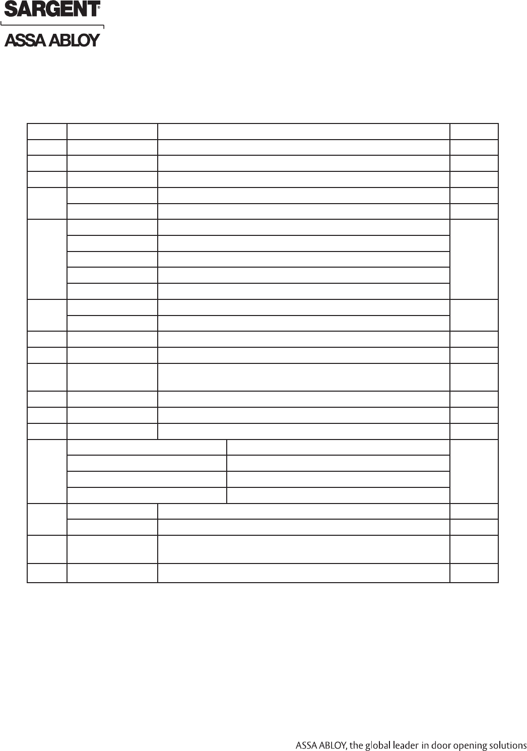
A. Verify Hand and Bevel of Door
Stand on outside/locked side of door when determining the door hand.
B. Door Preparation
Prior to installation, all holes must be free of burrs, debris and sharp edges.
Prepare door according to appropriate template (see website www.intelligentopenings.com):
• Wood door: A7457 (ships with product)
• Metal door: 4533
LH
Left Hand
Hinges Left
Open Inward
LHRB
Left Hand
Reverse Bevel
Hinges Left
Open Outward
RH
Right Hand
Hinges Right
Open Inward
RHRB
Right Hand
Reverse Bevel
Hinges Right
Open Outward
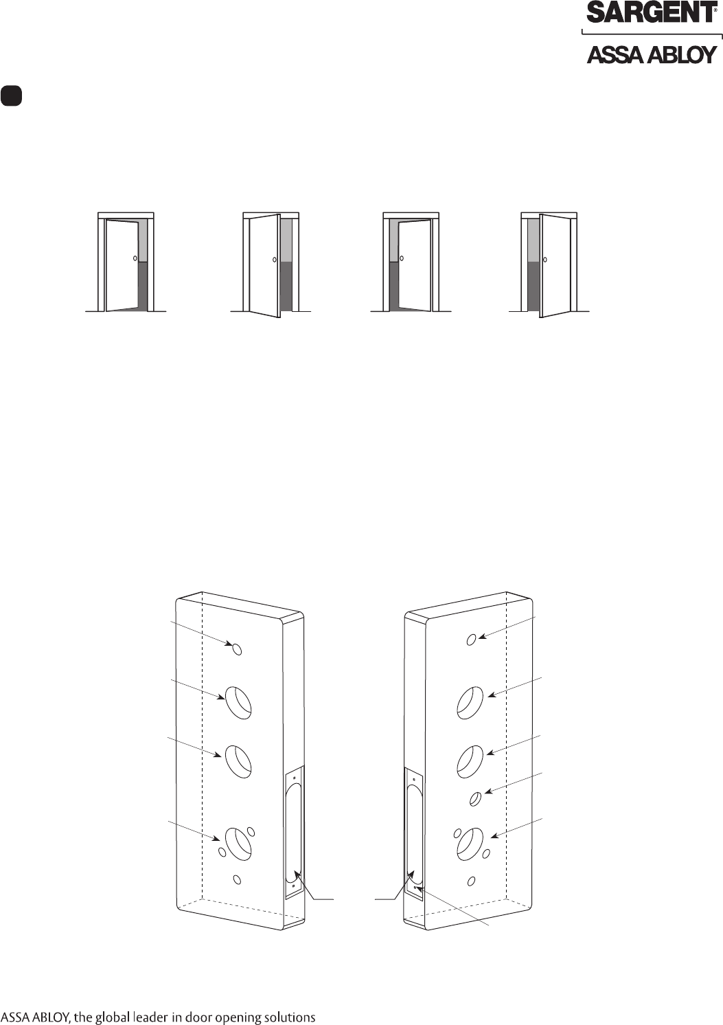
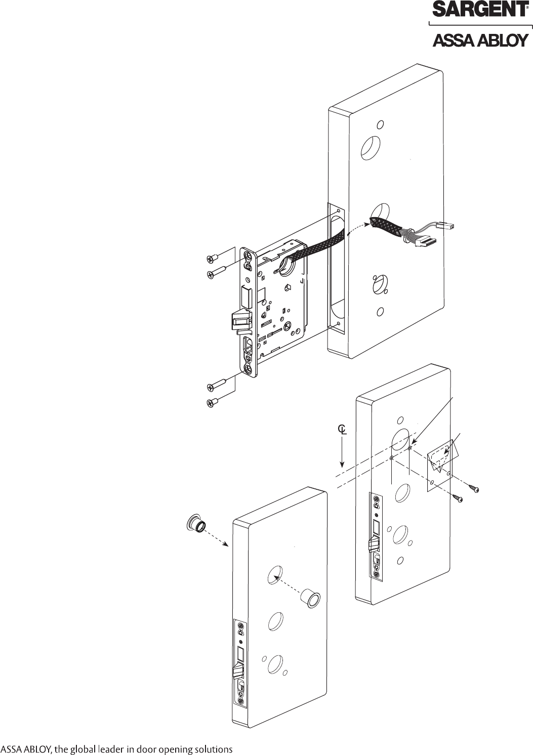
Step #1 – Door Preparation
Fig. 1A
Outside Cylinder Hole
(only with cylinder installation)
Outside of Door Inside of Door
Ribbon Cable Hole
(Controller to Keypad)
Lever Handle Hole
Through-bolt Hole
Ribbon Cable Hole
(Controller to Keypad)
Inside of Lockbody Wire Hole
Lever Handle Hole
Through-bolt Hole
Pre-drilled and/or
Tapped Holes
Mortised
Pocket
Thumb Turn Lever Hole
Fig. 1B
8 1-800-810-WIRE • www.sargentlock.com • A7786E
Copyright © 2010, Sargent Manufacturing Company, an ASSA ABLOY Group company. All rights reserved.
Reproductions in whole or in part without express written permission of Sargent Manufacturing Company is prohibited.
10/15/10
Profile Series v.S2 WiFi Mortise Lock
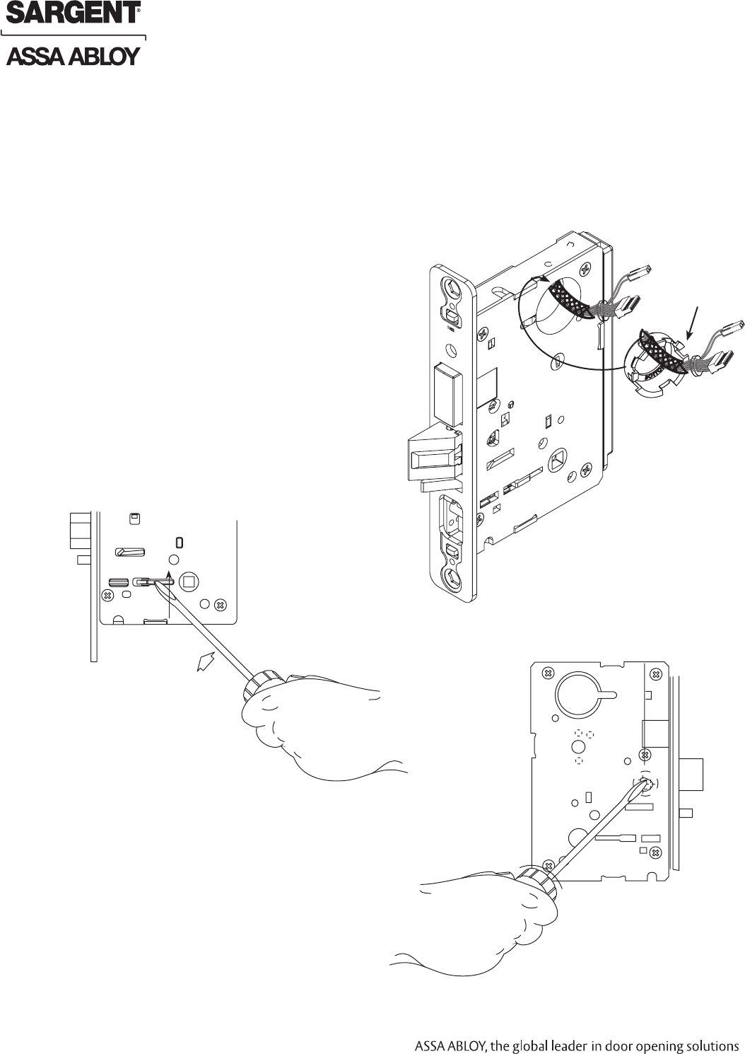
Step #2 – How to Change Hand of Lockbody
Beveled surface of latchbolt must face strike (Fig. 2C).
The deadlatch is self adjusting.
To change the hand of the latchbolt:
1. Insert the blade of a slotted screwdriver (>1/4")
into the spade shape slot behind latch.
2. Rotate the screwdriver 90° to push latchbolt out
until back of bolt clears lock case front.
3. Rotate latchbolt 180° until the latchbolt
drops back into the lockbody.
Note: Latch cannot be unscrewed.
Red surface of locking piece must face the outside/locked side of door. To rotate locking piece (Fig. 2A):
1. Position lock body with red surface of locking piece visible.
2. Insert blade type screwdriver into locking piece slot to rotate locking piece toward back of lock body.
3. Rotate the locking piece 180° until RED surface is
on opposite side.
Note: Red indicates locked side (outside).
Wire harness MUST exit through the
inside/non-cylinder side of the lockbody.
Red Locking Piece
Indicates Locked Side
Plastic
Retaining
Ring
Outside of Door
Fig. 2B
Slot
Connector
Push In
Right Hand Shown
Locking
Guide
Slot
Fig. 2A
Fig. 2C
A. Reverse Lock Hand
C. Reverse Latch Hand
Make sure the plastic retaining ring is seated
correctly (Fig. 2B):
1. The wires and the plastic retaining ring must
be located on the non-cylinder side.
2. Orient the plastic retaining ring so that the word
Bottom is located at the bottom of the cylinder hole.
3. Route the wires from the top of the cylinder hole
into the slot on the top of the plastic retaining ring,
NOT through the retaining ring.
B. Retaining Ring
10/15/10
1-800-810-WIRE • www.sargentlock.com • A7786E 9
Copyright © 2010, Sargent Manufacturing Company, an ASSA ABLOY Group company. All rights reserved.
Reproductions in whole or in part without express written permission of Sargent Manufacturing Company is prohibited.
Profile Series v.S2 WiFi Mortise Lock
Step #4 – Exterior Door Options
A. Fire Stop Plate
Fire-rated doors require a fire stop plate on the
outside of the door (Fig. 4A).
1. Drill (2) 1/8" x 1-1/4" deep holes in the door,
if not already present.
Refer to template for
fire-stop prep locations.
2. Attach with flap up and
out using (2) #8 x 1/2"
self-tapping screws for
wood and metal doors.
B. Weather Conduit
Install weather conduit (part number
52-2847) on NON Fire-Rated
exterior doors only (Fig. 4B).
Note: Once weather conduit is
assembled, it can be difficult to
take apart.
Fig. 4B
Weather
Conduit
Step #3 – Install Lockbody
To install lockbody:
1. Feed the wires first through the mortise pocket
and out the inside prep, followed by the lock-
body (Fig. 3A).
Note: Connectors and wires must be fed
through non-cylinder side.
2. The wires from the lockbody exit the inside door
prep through the mortise cutout.
3. Loosely secure the lockbody in the door with
two #12 x 1-1/4" wood screws or #12-24 x 1/2"
machine screws.
Note: Do not completely tighten at this time.
Fig. 4A
(2) 1/8” Diameter
Holes Required
Slot
(2) Self-Tapping
#8 x 1/2” Screws for
Wood and Metal Doors
Outside of Door
Fire
Stop
Plate
(2) #12-24 x 1/2" Long
Flat Head Screws
for Metal Doors
(2) #12 x 1-1/4” Long
Flat Head Screws
for Metal Doors
Fig. 3A
Mortise
Connectors
Inside of Door
10 1-800-810-WIRE • www.sargentlock.com • A7786E
Copyright © 2010, Sargent Manufacturing Company, an ASSA ABLOY Group company. All rights reserved.
Reproductions in whole or in part without express written permission of Sargent Manufacturing Company is prohibited.
10/15/10
Profile Series v.S2 WiFi Mortise Lock
Step #5 – Install Gasket (for Exterior Doors)
For exterior applications, use weather seal gasket between escutcheon
and outside door surface. To apply weatherseal gasket:
1. Carefully remove the backing from the gasket. (Fig. 5A).
2. Apply gasket to escutcheon:
a. Starting in one place, press the adhesive side
of the gasket firmly against the escutcheon.
b. Work around the escutcheon, pressing the
sticky side of the gasket firmly against the
escutcheon edge.
c. The gasket should be aligned so that all edges
of the escutcheon are covered.
3. Attach escutcheon to the door.
Note: The 43 cylinder may be used with or without a gasket.
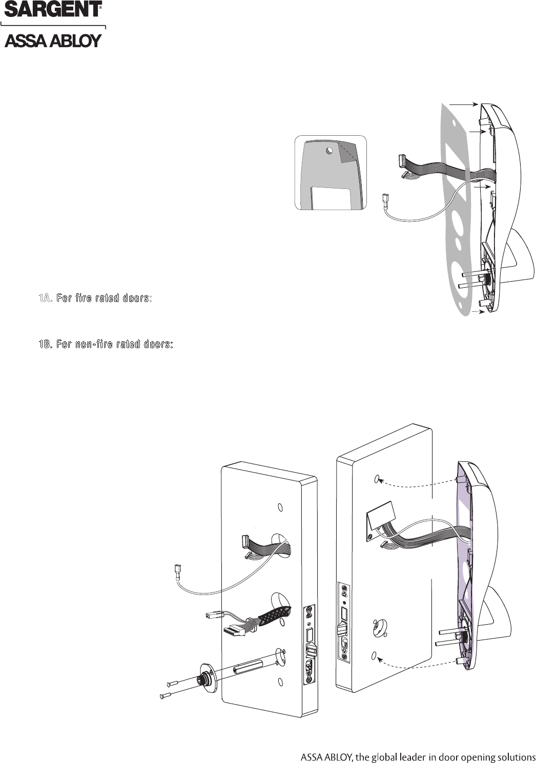
Step #6 – Install Gasket (for Exterior Doors)
1A. For fire rated doors: feed ribbon cable with connector and ground wire
from outside of door through weatherseal gasket and fire stop plate (Fig. 6A).
Note: Install ribbon cable with cable exiting down
1B. For non-fire rated doors: feed ribbon cable with connector and ground
wire from outside of door through weatherseal gasket (if used)
and weather conduit (Fig. 6B).
Note: Install ribbon cable with cable exiting down
2. With outside lever horizontal, locate the outside escutcheon on the door,
while directing the mounting posts through the door and lock body (Fig. 6B).
Make sure the lever spindle is properly engaged in lock.
7. On the inside of the door, insert spindle into square hole
of mortise lock.
8. Slide inside adapter and plate
assembly over spindle and loosely
secure with 2 through -bolt
screws (#8-32 x 5/8”).
Note: For 8276 and 8278,
loosely thread cylinder
through escutcheon
and into the lock body
before tightening the
lock case screws
and escutcheon
through bolts.
Inside of Door
Mortise Lock body
and AX Connectors
Fig. 6B
Reader
Cable
Ground
Wire (E1)
Antenna
(iCLASS)
Fig. 5A
Keypad
Ribbon
Cable
Ground
Wire
(E1)
Gasket
Antenna
(iCLASS)
Only
Fig. 5B
Antenna
(iCLASS
only)
Fig. 6A
Outside of Door
Keypad
Ribbon
Cable
Ground
Wire (E1)
10/15/10
1-800-810-WIRE • www.sargentlock.com • A7786E 11
Copyright © 2010, Sargent Manufacturing Company, an ASSA ABLOY Group company. All rights reserved.
Reproductions in whole or in part without express written permission of Sargent Manufacturing Company is prohibited.
Profile Series v.S2 WiFi Mortise Lock
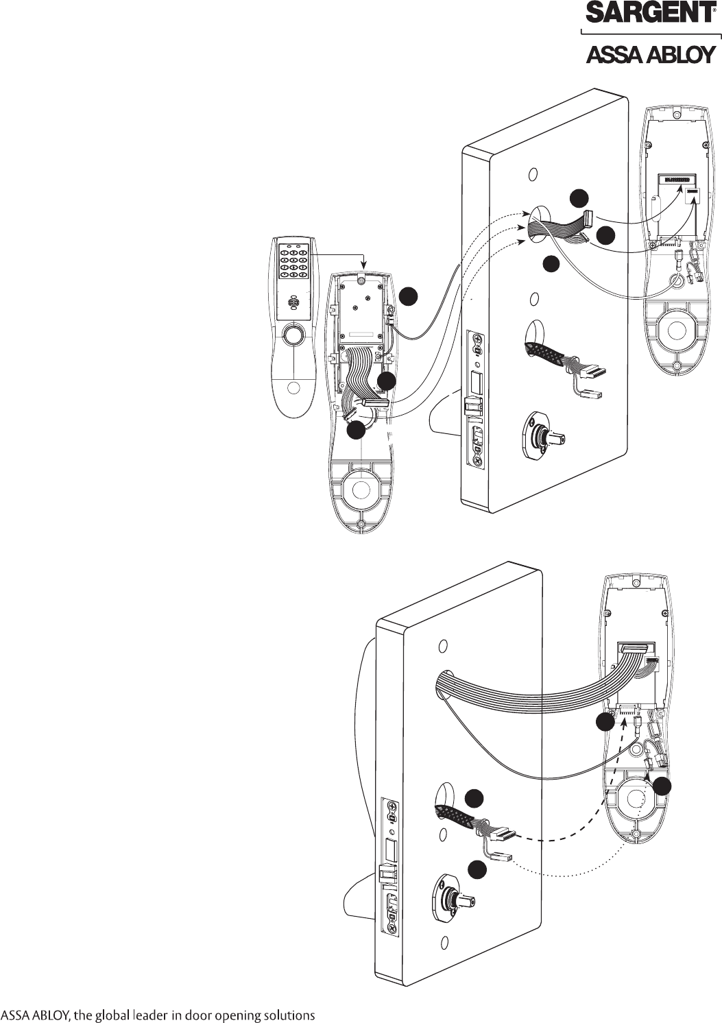
Step #7 – Inside Escutcheon Wire Connections
Images are shown without gasket. If gasket is necessary,
refer to Step #5.
Before the controller is attached to the door:
1. Attach the reader assembly
ribbon cable into the back of the
controller assembly (side that
faces towards the door when
mounted (Fig. 7A).
2. Attach the antenna to the
circuit board in the plastic
housing under the
controller assembly.
Note: The difference between
the wiring for the iCLASS 13.56
MHz reader and the 125 kHz
Prox is that the iCLASS wiring
includes an antenna wire.
3. Attach the ground wire
to the bottom of the
controller assembly (E1).
Step #8 – Lock Wire Connections
1. Connect the cable from the mortise lock
to the bottom of the controller assembly
(TB1, Fig. 8A).
2. Connect the AX/DPS connector to the
2-pin harness.
Ground
Wire
Fig. 7A
3
1
2
Antenna
(iCLASS)
Outside
Escutcheon
1
2
3
Ground
Wire
Reader
Cable
Antenna
(iCLASS)
Reader
Ribbon Cable
Mortise
Connector
Ground
Wire
Fig. 8A
Back
1
AX/DPS
2
Inside of Door
1
2
Outside
Escutcheon
Antenna
Unused
TB1
Reader
Ribbon Cable
12 1-800-810-WIRE • www.sargentlock.com • A7786E
Copyright © 2010, Sargent Manufacturing Company, an ASSA ABLOY Group company. All rights reserved.
Reproductions in whole or in part without express written permission of Sargent Manufacturing Company is prohibited.
10/15/10
Profile Series v.S2 WiFi Mortise Lock
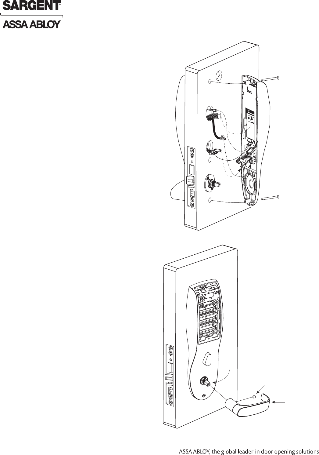
1. Slide lever handle onto spindle
until fully seated (Fig. 10A).
2. Tighten the set screw securely with
1/8" hex wrench.
Step #10 – Install Inside Lever
Step #9 – Install Inside Escutcheon
1. Gently fold the excess ribbon connector and ground
wire into the top hole, JST connectors and ground
wire into offset middle hole, and mortise and AX/DPS
wires into bottom hole, being careful not to pinch
wires (Fig. 9A).
2. Insert (2) #8-32 x 1-1/4" screws through inside
escutcheon and thread into outside escutcheon.
Straighten escutcheons and tighten securely.
Inside of Door
Fig. 10A
Spindle
Set Screw
Inside Lever
Inside of Door
Fig. 9A
10/15/10
1-800-810-WIRE • www.sargentlock.com • A7786E 13
Copyright © 2010, Sargent Manufacturing Company, an ASSA ABLOY Group company. All rights reserved.
Reproductions in whole or in part without express written permission of Sargent Manufacturing Company is prohibited.
Profile Series v.S2 WiFi Mortise Lock
Step #12 – Attach Front Plate
Attach front plate with (2) flat head screws.
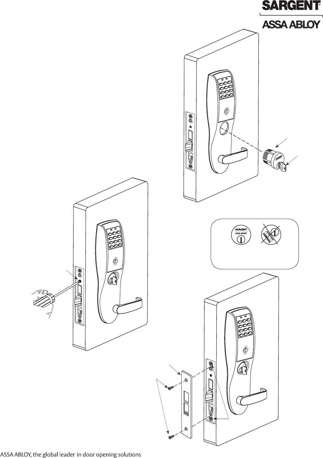
Step #11 – Install and Secure Cylinder
1. Slide cylinder through the spring and rosette/collar
and screw into lockbody, rotating the cylinder
clockwise (Fig. 11A).
Cylinder should be flush with rosette/collar.
Note: The 43 cylinder may be used when installing
this product with or without a gasket.
Note: SARGENT logo must be horizontal and
on the top of the cylinder (Fig. 11B).
2. Secure the cylinder by tightening cylinder clamp
screw located above the deadbolt using #2
Phillips screwdriver (Fig. 11C).
3. Using the key, test cylinder functions:
• 8278 Function: Key retracts latch.
• 8276 Function: Key retracts latch and projects
and retracts deadbolt.
Fig. 11B
Position cylinder so that the
SARGENT logo is right-side up.
Correct Incorrect
Fig. 11A
Outside of Door
Key
Type 43 Cylinder
Fig. 12A
Outside of Door
Front Plate
(2) Flat Head Screws
Lock body Screws
Cylinder Clamp Screw
#2 Phillips
Screwdriver
Outside of Door
Fig. 11C
14 1-800-810-WIRE • www.sargentlock.com • A7786E
Copyright © 2010, Sargent Manufacturing Company, an ASSA ABLOY Group company. All rights reserved.
Reproductions in whole or in part without express written permission of Sargent Manufacturing Company is prohibited.
10/15/10
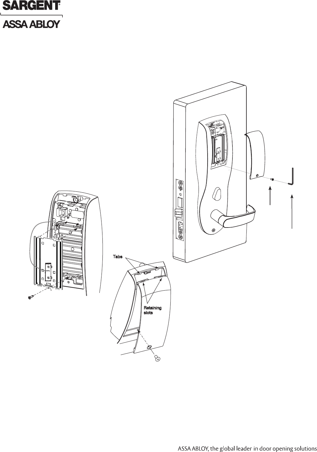
Profile Series v.S2 WiFi Mortise Lock
IMPORTANT: Do not install batteries if controller is powered by external power supply.
1. To install or replace batteries, first remove the battery cover
(if necessary) using the provided security tool (Fig.13A).
2. Unscrew the bottom screw of the battery keeper
and remove the battery keeper, being careful
not to break the tabs at top that hold it in
place (Fig.13B)
3. Place (6) “AA” alkaline batteries in the
compartment, being careful to align
polarity properly.
4. Replace battery keeper being careful to engage
tabs at top to hold it in place (Fig. 13B).
5. Attach battery cover to inside escutcheon,
making sure to line up tabs with retaining
slots in battery cover.
6. Secure with the security screw
using tool. (Fig. 13A).
Step #13 – Install (or Replace) Batteries
Fig. 13B
Fig. 13C
Security Allen Wrench
01-0297 included
Security
screw
Battery
Cover
Fig. 13A
10/15/10
1-800-810-WIRE • www.sargentlock.com • A7786E 15
Copyright © 2010, Sargent Manufacturing Company, an ASSA ABLOY Group company. All rights reserved.
Reproductions in whole or in part without express written permission of Sargent Manufacturing Company is prohibited.
Profile Series v.S2 WiFi Mortise Lock
For 8276 and 8278 Function mortise locks with cylinders:
1. Insert key into cylinder and rotate (There should be no friction against lock case, wire harness
or any other obstructions.
Refer to Section 7, Step 8 if harness friction exists).
2. The key will retract the latch.
Key should rotate freely.
3. If the deadbolt is thrown, the key will retract both the deadbolt and the latch.
4. Inside lever retracts latch and deadbolt (if provided).
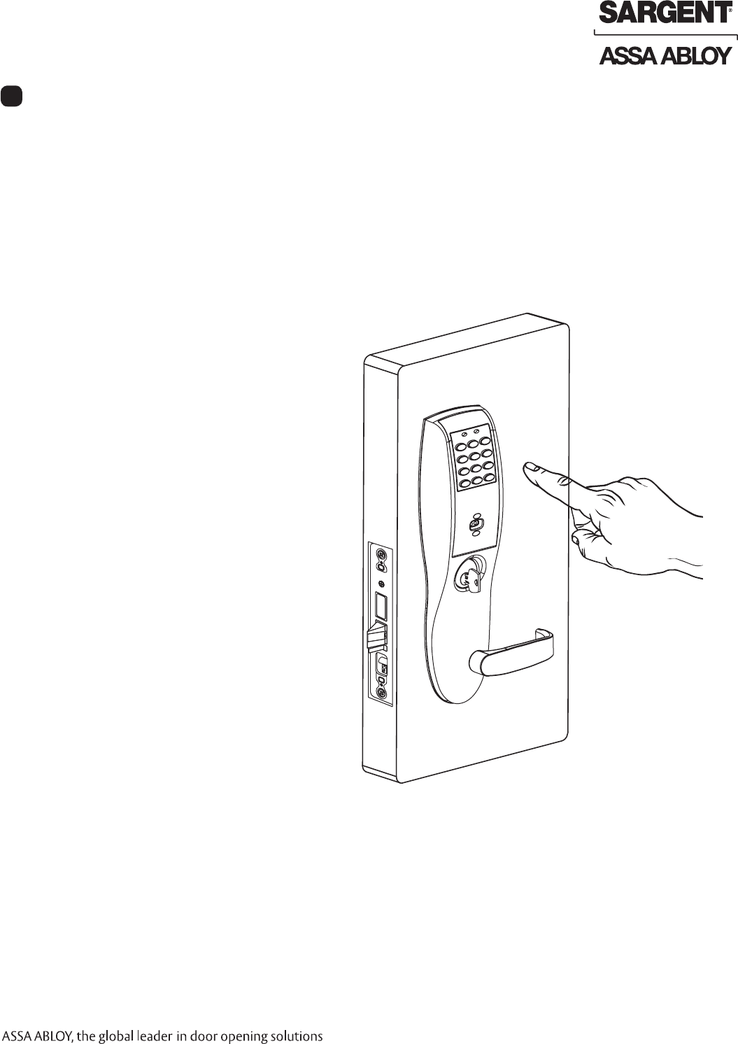
5. Enter the code provided on keypad units
or present the prox card provided
for prox units.
This should unlock the outside lever
and allow the latch to be retracted.
Refer to the Network & Lock Configuration Tool
User Manual (WFCD1) for additional information.
Operational Check
9
.

SARGENT Manufacturing
100 Sargent Drive
New Haven, CT 06511 USA
800-810-WIRE (9473) • www.sargentlock.com
Founded in the early 1800s, SARGENT® is a market leader in locksets, cylinders, door closers, exit devices,
electro-mechanical products and access control systems for new construction, renovation, and replacement applications.
The company’s customer base includes commercial construction, institutional, and industrial markets.
Copyright © 2010, Sargent Manufacturing Company, an ASSA ABLOY Group company. All rights reserved.
Reproduction in whole or in part without the express written permission of Sargent Manufacturing Company is prohibited.
ASSA ABLOY is the global leader in door opening solutions, dedicated to
satisfying end-user needs for security, safety and convenience. A7786E-10/10