ASUSTeK Computer AAM6KVIB6 4-PORT WIRELESS ETHERNET ROUTER User Manual 4 Port Wireless Ethernet Router
ASUSTeK Computer Inc 4-PORT WIRELESS ETHERNET ROUTER 4 Port Wireless Ethernet Router
USERS MANUAL
4-Port Wireless Ethernet Router
AAM6020VI-B6
User Manual
Version 1.0
Version Date: June 8, 2005

4-Port Wireless Ethernet Router
User Manual
1
Version 1.0
Table of Contents
GENERAL INFORMATION ............................................................................3
Package Contents ...............................................................................3
Safety Instructions—Please read. ....................................................3
Front Panel View..................................................................................4
Back Panel View ..................................................................................5
Description .............................................................................................5
INSTALLING THE ROUTER ..........................................................................6
Connect the ADSL Line and Telephone........................................6
Connect the PC to the Router ..........................................................6
Connect the Power Adapter..............................................................6
INSTALLATION DIAGRAM ............................................................................7
CONFIGURING YOUR COMPUTER.............................................................8
Windows 2000 ......................................................................................8
Windows XP ..........................................................................................9
LOGGING INTO THE ROUTER .................................................................. 10
DEVICE INFO ............................................................................................. 11
Summary ............................................................................................. 11
WAN ...................................................................................................... 12
STATISTICS ....................................................................................... 12
LAN Statistics................................................................................. 12
WAN Statistics............................................................................... 13
ATM Statistics ................................................................................ 13
ADSL Statistics.............................................................................. 14
ADSL BER Test............................................................................. 15
Route .................................................................................................... 17
ARP ....................................................................................................... 18
QUICK SETUP ........................................................................................... 19
ATM PVC Configuration.................................................................. 19
ADVANCED SETUP ................................................................................... 21
WAN ...................................................................................................... 21
Connection Type........................................................................... 23
NAT ....................................................................................................... 27
Virtual Servers ............................................................................... 27
Port Triggering ............................................................................... 28
DMZ Host ........................................................................................ 30
Firewall................................................................................................. 30
IP Filtering—Outgoing................................................................... 30
IP Filtering—Incoming................................................................... 31
MAC Filtering ................................................................................. 32

4-Port Wireless Ethernet Router
User Manual
2
Version 1.0
Port Mapping...................................................................................... 33
Quality of Service.............................................................................. 35
Routing................................................................................................. 36
Default Gateway............................................................................ 36
Static Route.................................................................................... 36
RIP .................................................................................................... 37
DNS....................................................................................................... 38
DNS Server..................................................................................... 38
Dynamic DNS ................................................................................ 38
ADSL..................................................................................................... 39
DSL Advanced Settings .............................................................. 40
Tone Settings ................................................................................. 40
WIRELESS ................................................................................................. 42
Basic ..................................................................................................... 42
Security ................................................................................................ 42
MAC Filter ........................................................................................... 44
Wireless Bridge ................................................................................. 45
Advanced............................................................................................. 46
TROUBLESHOOTING—DIAGNOSTICS ..................................................... 48
MANAGEMENT........................................................................................... 48
Settings ................................................................................................ 48
Backup Settings ............................................................................ 48
Restore User Settings ................................................................. 49
Restore Default.............................................................................. 50
System Log ......................................................................................... 50
Configure System Log................................................................. 51
SNMP ................................................................................................... 52
Internet Times .................................................................................... 52
Access Control................................................................................... 53
Services ........................................................................................... 53
IP Addresses .................................................................................. 53
Passwords ...................................................................................... 54
Update Software................................................................................ 55
Reboot Router.................................................................................... 55
APPENDIX .................................................................................................. 56
FCC Warning Statement ................................................................. 56
Declaration of Conformity for R&TTE directive 1999/5/EC .. 57
CE Mark Warning.............................................................................. 57
4-Port Wireless Ethernet Router
User Manual
3
Version 1.0
General Information
The 4-Port Wireless Ethernet Router features 4 LAN ports and a
wireless ability.
Package Contents
Included in the package is one of each of the following—
•4-Port wireless Ethernet router
•15 VAC AC power adapter
•RJ-11 telephone cable
•RJ-45 Ethernet cable
•Splitter
•User Manual
•Place your router on a flat surface close to the cables in a
location with sufficient ventilation.
•To prevent overheating, do not obstruct the ventilation
openings of this equipment.
•Plug this equipment into a surge protector to reduce the risk
of damage from power surges and lightning strikes.
•Operate this equipment only from an electrical outlet with
the correct power source as indicated on the adapter.
•Do not open the cover of this equipment. Opening the
cover will void any warranties on the equipment.
•Unplug equipment first before cleaning. A damp cloth can
be used to clean the equipment. Do not use liquid / aerosol
cleaners or magnetic / static cleaning devices.
Safety Instruction
s
—
Please read.
4-Port Wireless Ethernet Router
User Manual
4
Version 1.0
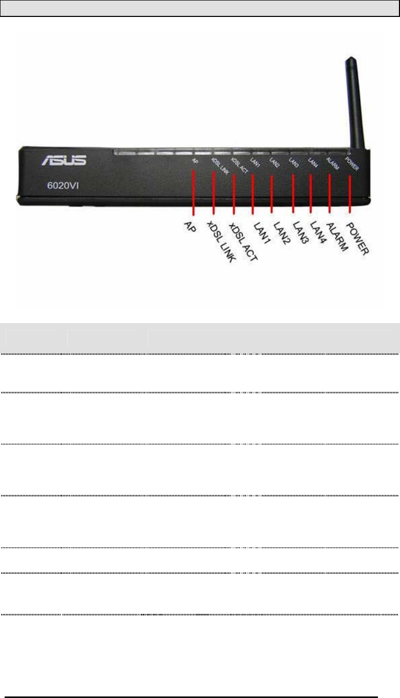
Front Panel View
LED Mode Indication
Solid Wireless is enabled.
No light Wireless is disabled.AP
Blinking There is wireless traffic.
Solid ADSL is connected.
No light ADSL is not connected. The ALARM led will be
red.
XDSL
Link
Blinking The router is connected to ADSL.
Solid ADSL is connected, and there is no ADSL traffic.
No light ADSL is not connected.
XDSL
ACT Quick
blinking
There is ADSL traffic.
Solid Router is connected to the LAN.
No light No connection to the LAN. Check if the LAN
cable is connected to the router.
LAN1-
LAN4
Blinking LAN traffic
Solid (red) ADSL is not connected.
ALARM No light ADSL is connected.
Solid Router is powered on.
POWER No light Router is not powered. Check if the router is
plugged in and if the power switch is turned on.
4-Port Wireless Ethernet Router
User Manual
5
Version 1.0
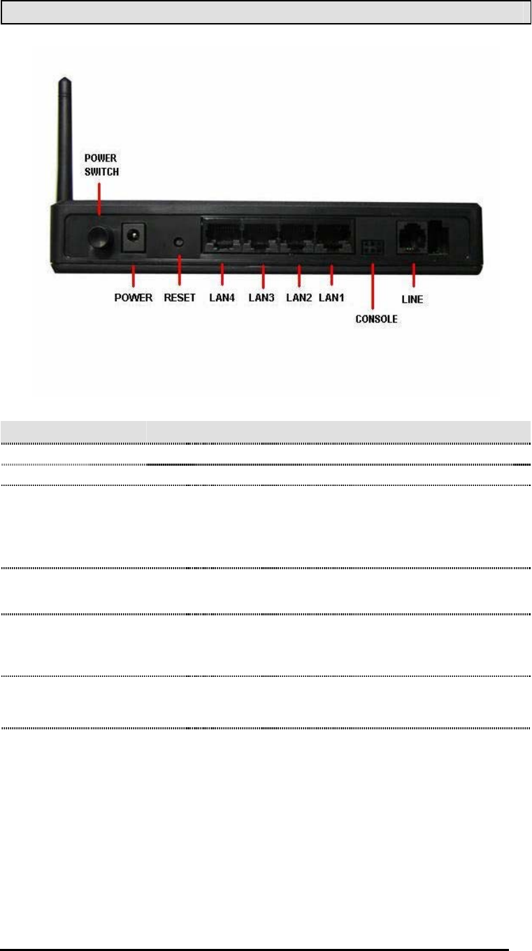
Back Panel View
Port Description
Power Switchh Press to turn the router on and off.
Powerr Connects to a 15 VAC AC power adapter.
Reset
Restart
—press the button for less than 4
seconds.
Default settings
—press the button for 4
seconds or longer.
LAN1-LAN4 RJ-45 connects the unit to an Ethernet device
such as a PC or a switch.
Console
NOTE:
To be used by maintenance
professionals only. If the router needs repair,
bring it to a service professional.
Linee RJ-11 cable connects to the splitter provided.
4-Port Wireless Ethernet Router
User Manual
6
Version 1.0
Installing the Router
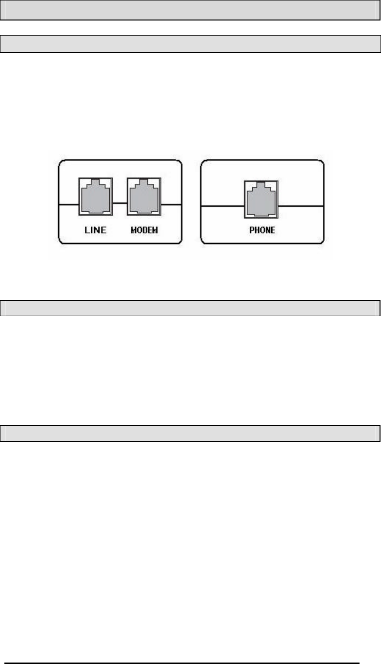
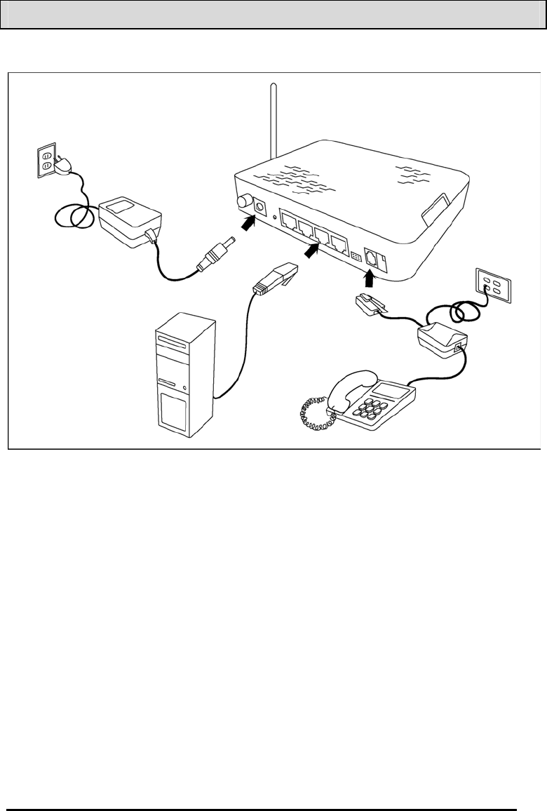
Connect the ADSL Line and Telephone
An RJ-11 cable will be connected to the wall phone jack and the
line-end of the splitter. Connect another RJ-11 phone wire from
the modem-end of the splitter to the port labeled “ line” on the
router. A third RJ-11 phone wire will be needed to connect the
telephone to the phone-end of the splitter.
NOTE: See connections on the installation diagram.
Connect the PC to the Router
Use the Ethernet cable to connect your computer directly to the
router. Connect one end of the Ethernet cable to one of the ports
labeled LAN on the rear panel of the router and connect the other
end to the Ethernet port of your computer. Attach any additional
PCs to the router using RJ-45 cables to the port labeled LAN on
the rear panel of the router.
Connect the Power Adapter
Complete the process by connecting the AC power adapter to the
POWER connector on the back of the device and plug the adapter
into a wall outlet or power strip. Then turn on and boot up your
PC and any LAN devices, such as hubs or switches, and any
computers connected to them.
4-Port Wireless Ethernet Router
User Manual
7
Version 1.0
Installation Diagram

4-Port Wireless Ethernet Router
User Manual
8
Version 1.0
Configuring Your Computer
Prior to accessing the router through the LAN port, note the
following necessary configurations —
•Your PC’s TCP/IP address: 192.168.1.___( the last number
is any number between 3 and 254)
•The router’s default IP address: 192.168.1.1
•Subnet mask: 255.255.255.0
Below are the procedures for configuring your computer. Follow
the instructions for the operating system that you are using.
Windows 2000
1. In the Windows taskbar, click on the Start button and point
to Settings, Control Panel, and Network and Dial-up
Connections (in that order).
2. Click on Local Area Connection. When you have the Local
Area Connection Status window open, click on Propertiess.
3. Listed in the window are the installed network components.
If the list includes Internet Protocol (TCP/IP), then the
protocol has already been enabled, and you can skip to
Step 10.
4. If Internet Protocol (TCP/IP) does not appear as an
installed component, then click on Installl.
5. In the Select Network Component Type window, click on
protocol and then the Addd button.
6. Select Internet Protocol (TCP/IP) from the list and then click
on OKK.
7. If prompted to restart your computer with the new settings,
click OKK.
8. After your computer restarts, click on the Network and Dial-
up Connections icon again, and right click on the Local
Area Connection icon and then select Properties.

4-Port Wireless Ethernet Router
User Manual
9
Version 1.0
9. In the Local Area Connection Properties dialog box, select
Internet Protocol (TCP/IP) and then click on Propertiess.
10. In the Internet Protocol (TCP/IP) Properties dialog box,
click in the radio button labeled Use the following IP
addresss and type 192.168.1.x (where x is any number
between 2 and 254) and 255.255.255.0 in the IP address
field and Subnet Mask field.
11. Click on OKK twice to save your changes and then close
the Control Panell.
Windows XP
1. In the Windows taskbar, click on the Start button and point
to Settings and then click Network Connections.
2. In the Network Connections window, right click on the Local
Area Connection icon and click on properties.
3. Listed in the Local Area Connection window are the
installed network components. Make sure the box for
Internet Protocol (TCP/IP) is checked and then click on
Propertiess.
4. In the Internet Protocol (TCP/IP) Properties dialog box, click
in the radio button labeled Use the following IP addresss and
type 192.168.1.x (where x is any number between 2 and
254) and 255.255.255.0 in the IP address field and Subnet
Mask field.
5. Click on OKK twice to save your changes and then close the
Control Panell.
4-Port Wireless Ethernet Router
User Manual
10
Version 1.0
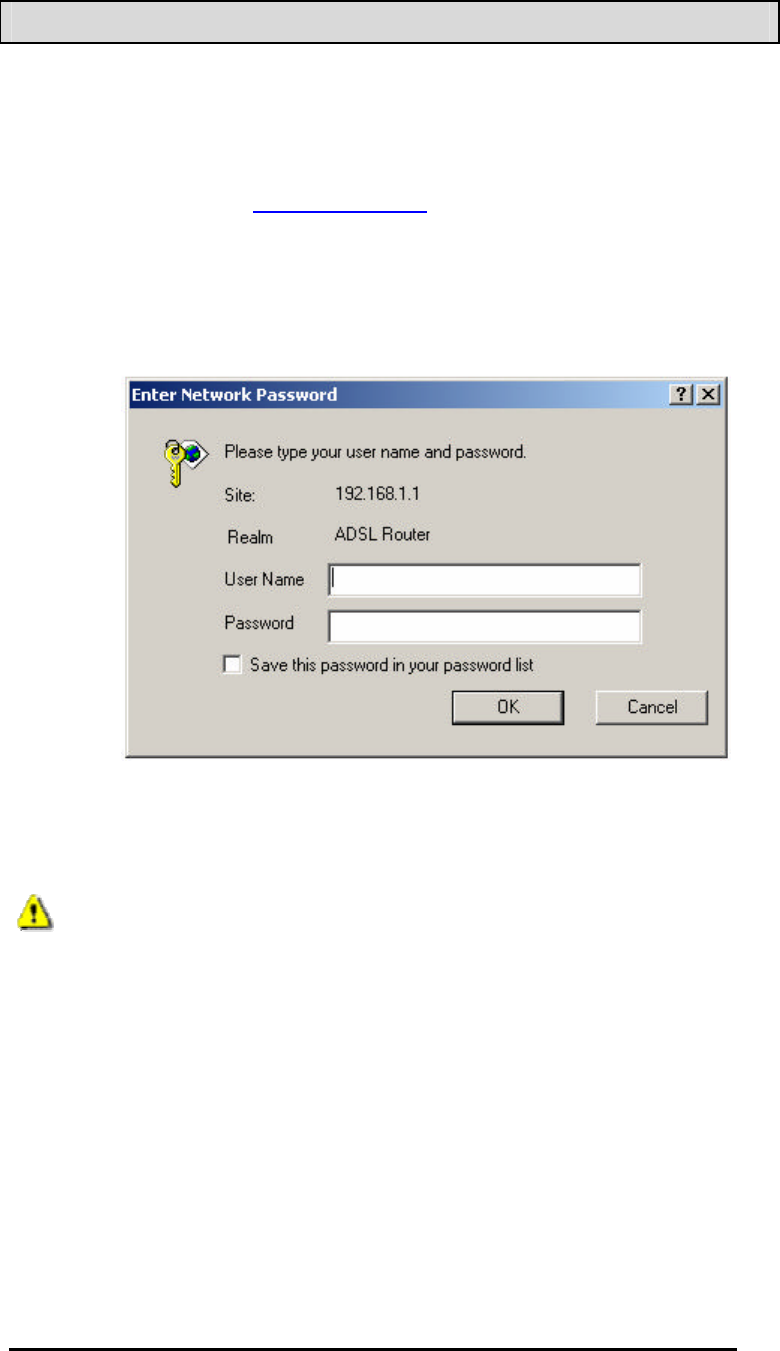
Logging into the Router
This section explains how to log in to your router using the
following steps—
1.. Launch your web browser.
2.. Enter the URL http://192.168.1.1 in the address bar and click
on Enterr.
A login screen like the one below will be displayed after you
connect to the user interface.
3. Enter your user name and password, and then click on OK
to display the user interface.
NOTE: There are two default user name and password
combinations. The user / user name and password combination
can display device status, but cannot change or save
configurations. The admin / admin combination can perform all
functions. Passwords can be changed at any time.
4-Port Wireless Ethernet Router
User Manual
11
Version 1.0
Device Info
This section describes the system information that can be
accessed using the menu items under Device Info.
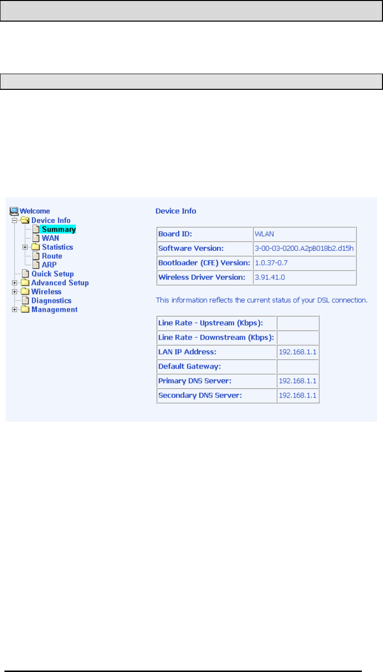
Summary
Access the general status report from the router by clicking on
“Summaryy” under “Device Infoo” . It shows information about the
router such as the version of the software, bootloader, etc. It also
displays the current status of your DSL connection as shown
below—
4-Port Wireless Ethernet Router
User Manual
12
Version 1.0
WAN
Access the WAN status report from the router by clicking on
“WANN” under “Device Info”.
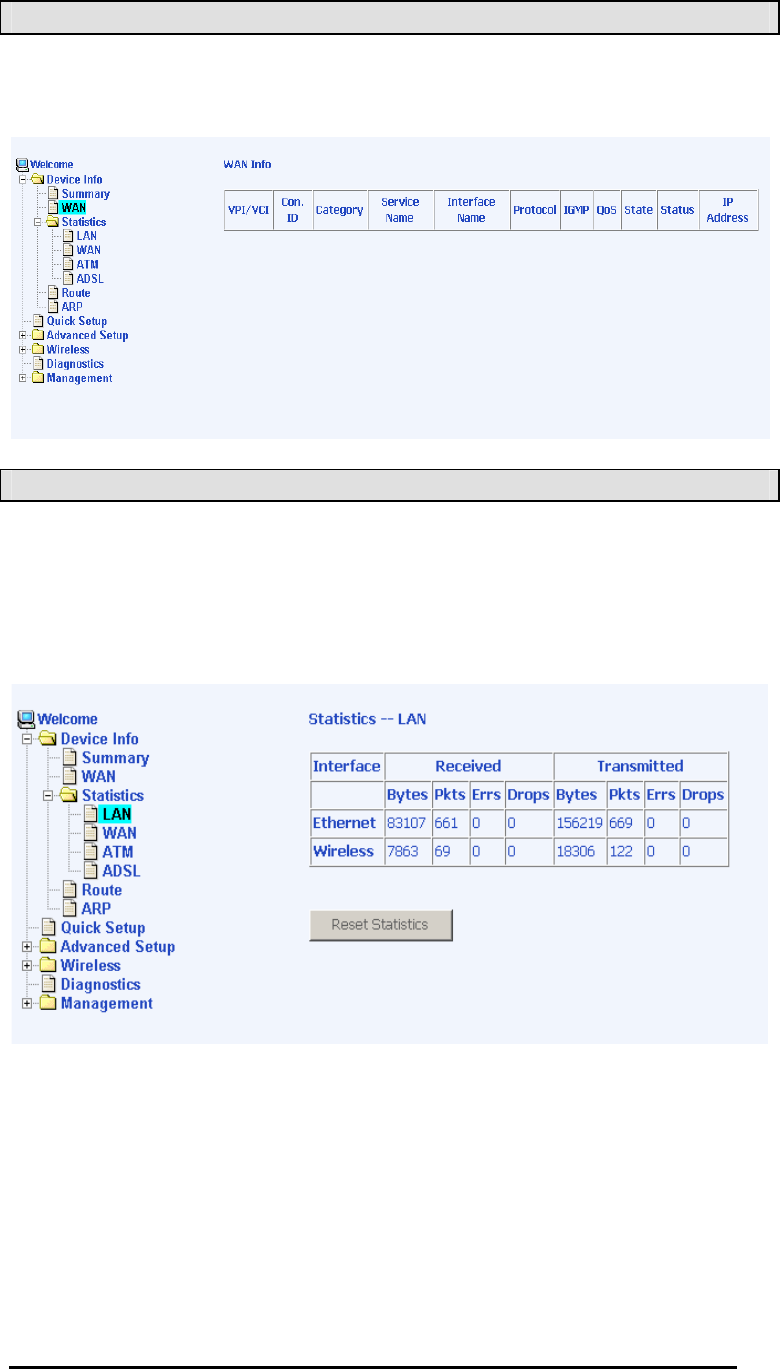
STATISTICS
LAN Statistics
Access the LAN statistics from the router by clicking on the “ LAN”
item under “ Statistics” .
4-Port Wireless Ethernet Router
User Manual
13
Version 1.0
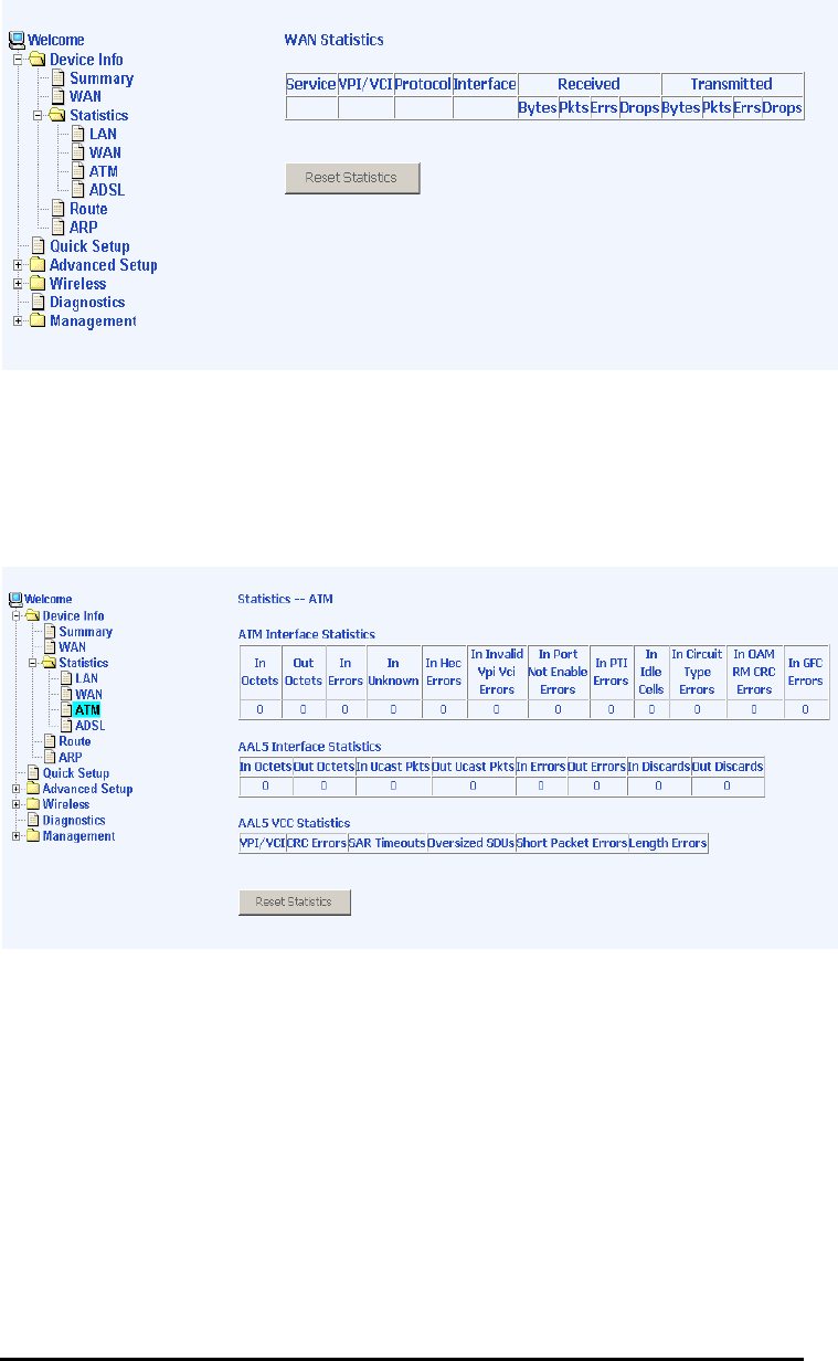
WAN Statistics
Access the WAN statistics from the router by clicking on the
“WANN” item under “Statisticss” .
ATM Statistics
Access ATM statistics from the router by clicking on the “ATMM”
item under “Statisticss”.
4-Port Wireless Ethernet Router
User Manual
14
Version 1.0
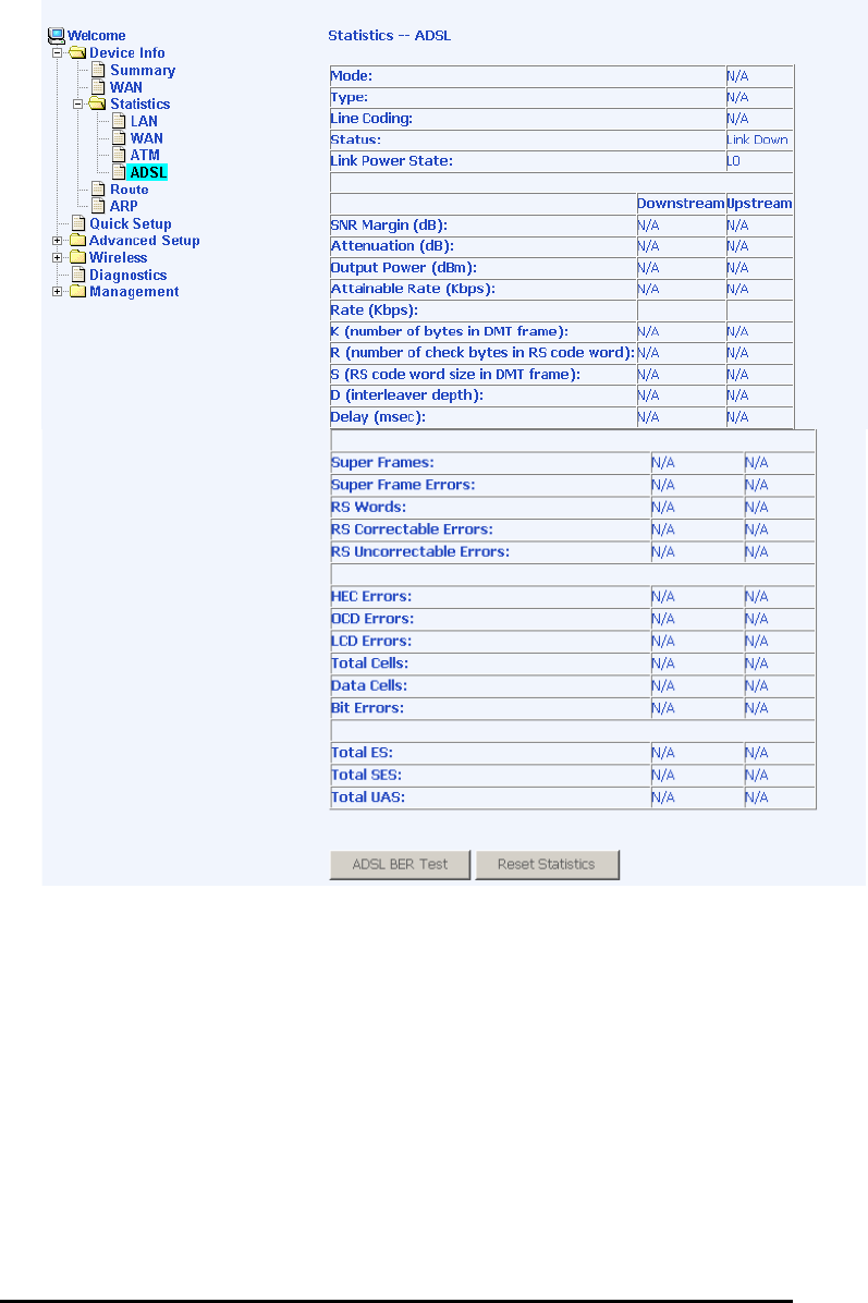
ADSL Statistics
You can view ADSL statistics by clicking on the “ADSLL” item
under “Statisticss” . Information contained in this screen is useful
for troubleshooting and diagnostics of connection problems.
4-Port Wireless Ethernet Router
User Manual
15
Version 1.0
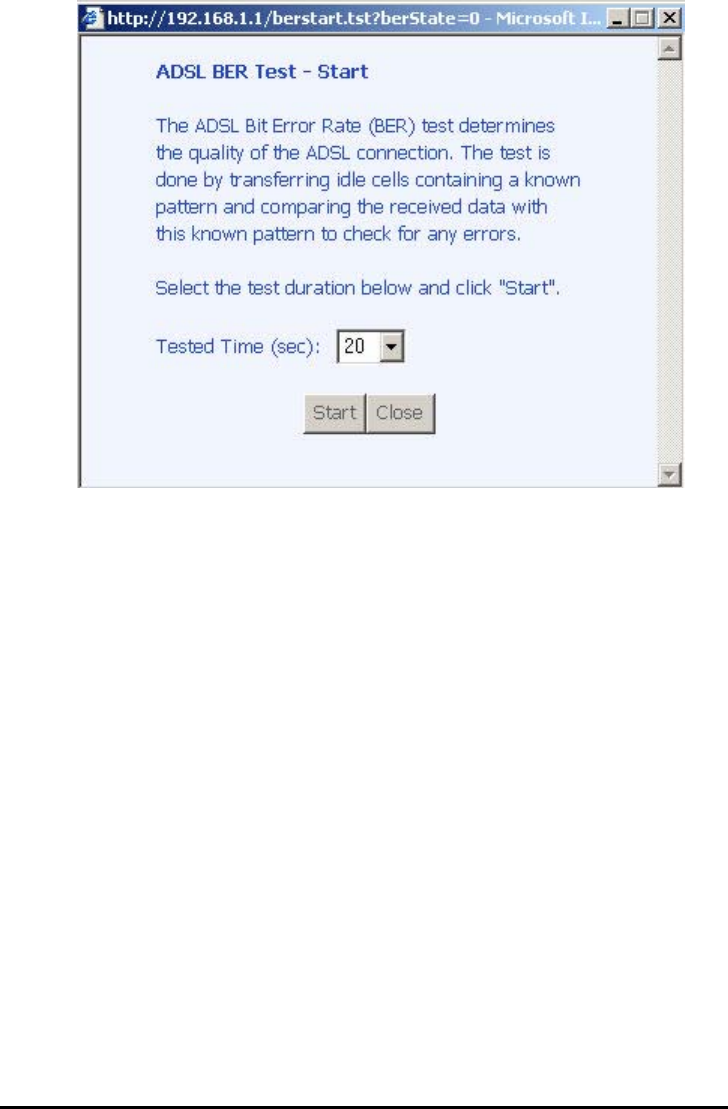
ADSL BER Test
ABit Error Rate Test (BER Test) is a test that reflects the ratio of
error bits to the total number transmitted.
If you click on the ADSL BER Test button at the bottom of the
ADSL Statistics page, the following pop-up screen will appear
allowing you to set the tested time and to begin the test.
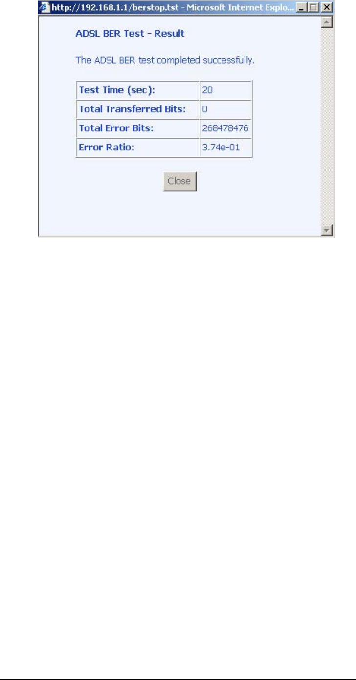
Below is an ADSL BER Test result screen displaying information
about the test and the error bits and ratio.
4-Port Wireless Ethernet Router
User Manual
16
Version 1.0
4-Port Wireless Ethernet Router
User Manual
17
Version 1.0
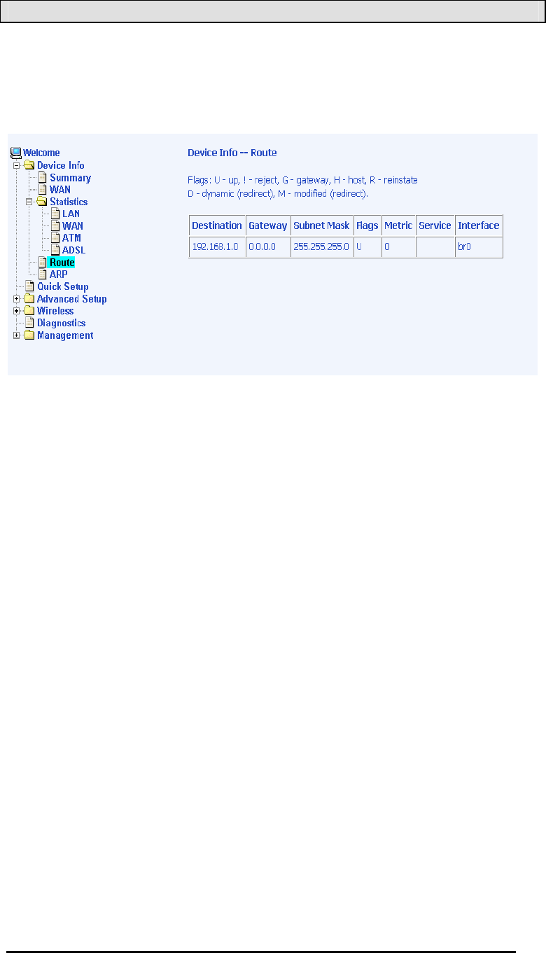
Route
Access the routing status report from the router by clicking on the
“Routee” item under “Device Infoo”.
4-Port Wireless Ethernet Router
User Manual
18
Version 1.0
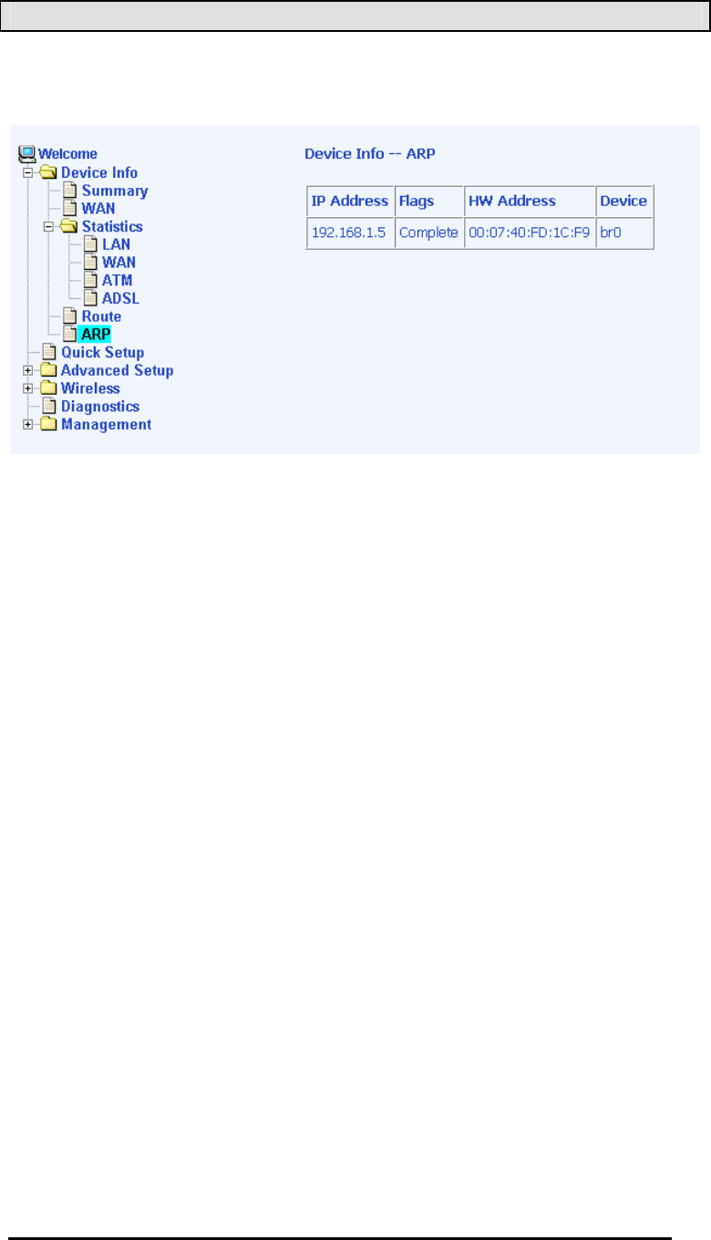
ARP
Access the ARP status report from the router by clicking on the
“ARPP” item under “ Device Infoo” .
4-Port Wireless Ethernet Router
User Manual
19
Version 1.0
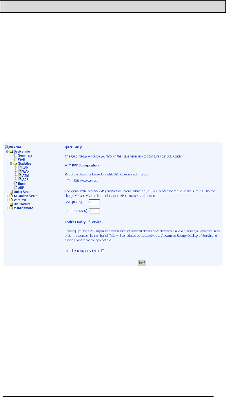
Quick Setup
This section will explain how to configure the router.
ATM PVC Configuration
To enable the auto-connect process, click on the box labeled DSL
Auto-connect, a process that will automatically detect the first
usable PVC and automatically detect PPPoE, PPPoA, and Bridge
Protocol (with DHCP Server available). To continue, click on the
Nextt button.
If you do not use DSL Auto-connect, then you may need to
change the VPI and VCI numbers. Quality of service can also be
enabled on this screen.
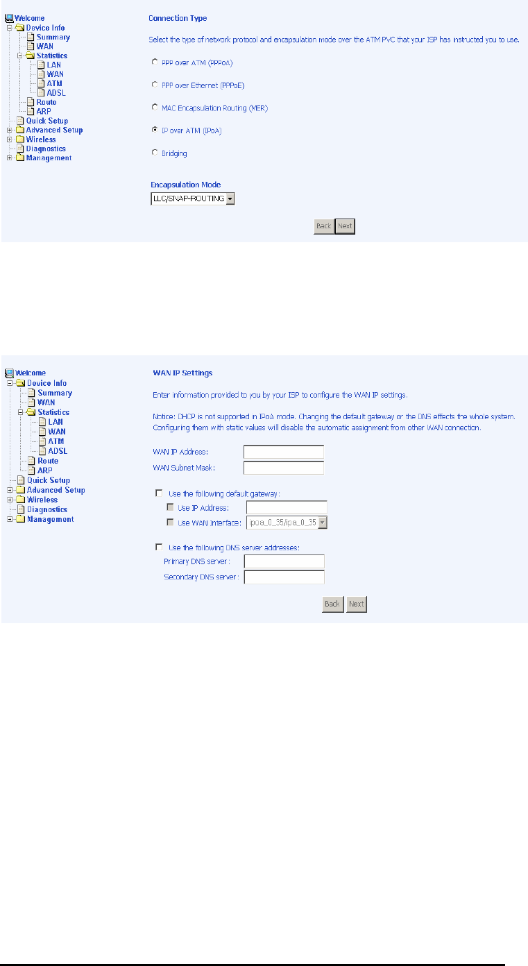
Furthermore, if you do not use DSL Auto-connect, then you will
need to select the connection type and encapsulation mode from
a list as shown below.
4-Port Wireless Ethernet Router
User Manual
20
Version 1.0
The next screen to appear will depend on the connection type that
was selected in the previous screen. The following screen is a
result of choosing IP over ATM (IPoA) as the connection type.
4-Port Wireless Ethernet Router
User Manual
21
Version 1.0
Advanced Setup
This section contains information about WAN, LAN, and ADSL
settings.
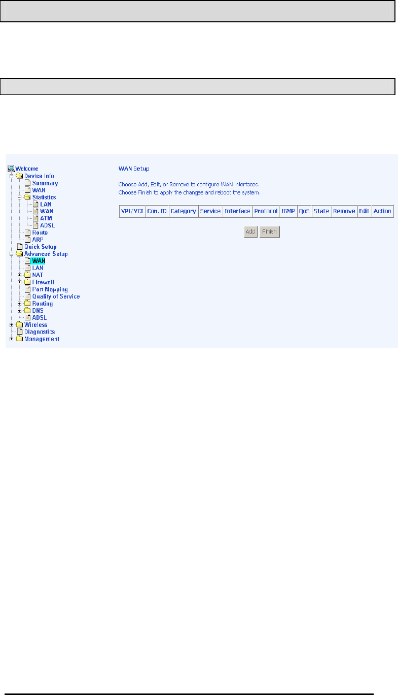
WAN
Configure the WAN settings as provided by your ISP.
Click on the Addd button if you want to add a new rule for the WAN
interface. The ATM PVC Configuration screen appears.
The ATM PVC Configuration screen allows you to configure an
ATM PVC identifier (VPI and VCI) and select a service category.

4-Port Wireless Ethernet Router
User Manual
22
Version 1.0
Verify the following values with your ISP before you change them.
•VPI:: Virtual Path Identifier. The valid range is 0 to 255.
•VCI:: Virtual Channel Identifier. The valid range is 32 to
65535.
•Service Category:: Five classes of traffic are listed—
oUBR Without PCR
oUBR With PCR
oCBR
oNon Realtime VBR
oRealtime VBR
Enabling QoS for a PVC improves performance for selected
classes of applications. However, since QoS also consumes
system resources, the number of PVCs is reduced. If you want to
enable QoS service, click on the Enable Quality Of Servicee check
box.
4-Port Wireless Ethernet Router
User Manual
23
Version 1.0
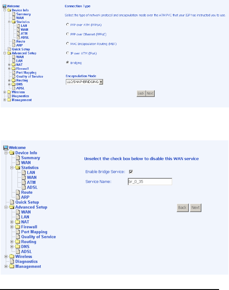
Connection Type
This screen shows the below types of network protocols and
encapsulation modes—
•PPP over ATM (PPPoA)
•PPP over Ethernet (PPPoE)
•MAC Encapsulation Routing (MER)
•IP over ATM (IpoA)
•Bridging
Select the mode that your ISP has instructed you to use and click
on Nextt.
After you click on Nextt, the below screen appears allowing you
disable the bridge service if desired.
4-Port Wireless Ethernet Router
User Manual
24
Version 1.0
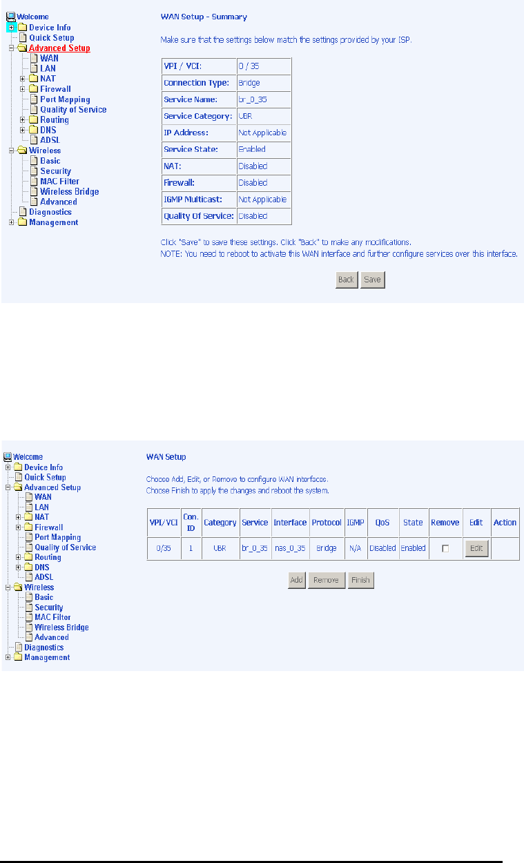
When the settings are complete, the next screen shows a WAN
Setup – Summary screen displaying the WAN configurations
made.
Click on the Savee button when the settings are correct. The
below screen will appear showing the WAN settings that you
made. When satisfied with the settings, and no changes are
necessary, click on the Finishh button. To remove any settings,
click on the Removee button.

4-Port Wireless Ethernet Router
User Manual
25
Version 1.0
After selecting the Finishh button, the below screen will appear. At
this point, the router will reboot to save the changes made.
4-Port Wireless Ethernet Router
User Manual
26
Version 1.0
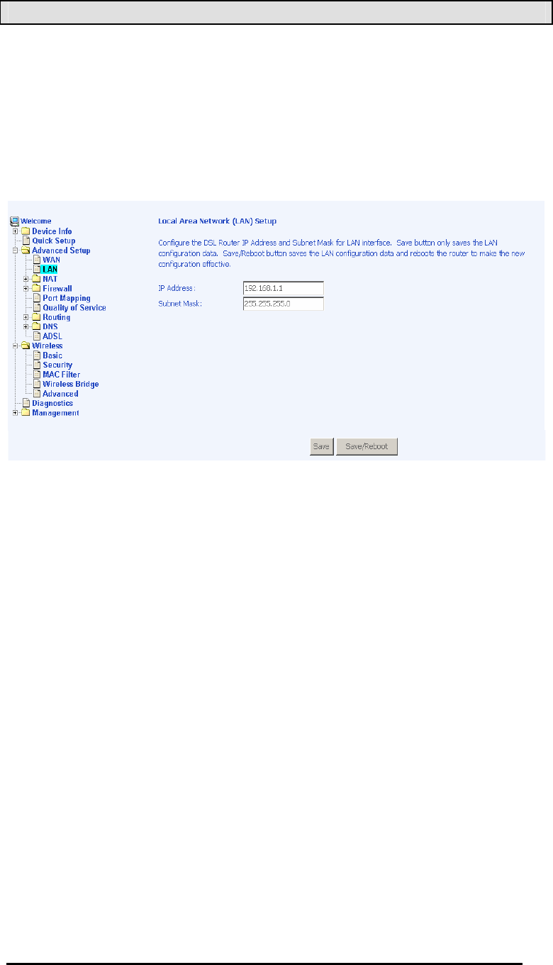
LAN Local Area Network (LAN) Setup
You can configure the DSL Router IP address and Subnet Mask
for the LAN interface to correspond your LAN’s IP Subnet. The
Savee button only saves the LAN configuration data, but does not
apply the configurations. Select the Save/Reboott button to save
the LAN configuration data and reboot the router and apply the
new configurations.
4-Port Wireless Ethernet Router
User Manual
27
Version 1.0
NAT
If you enable NAT (Network Address Translation), you can
configure the Virtual Server, Port Triggering, and DMZ Host.
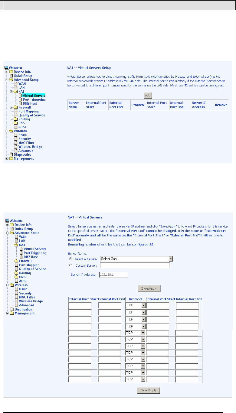
Virtual Servers
A virtual server allows you to direct incoming traffic from the WAN
side to a specific IP address on the LAN side. Select the virtual
server from the drop-down list and complete the server IP address,
then click on the Save / Apply button.
4-Port Wireless Ethernet Router
User Manual
28
Version 1.0
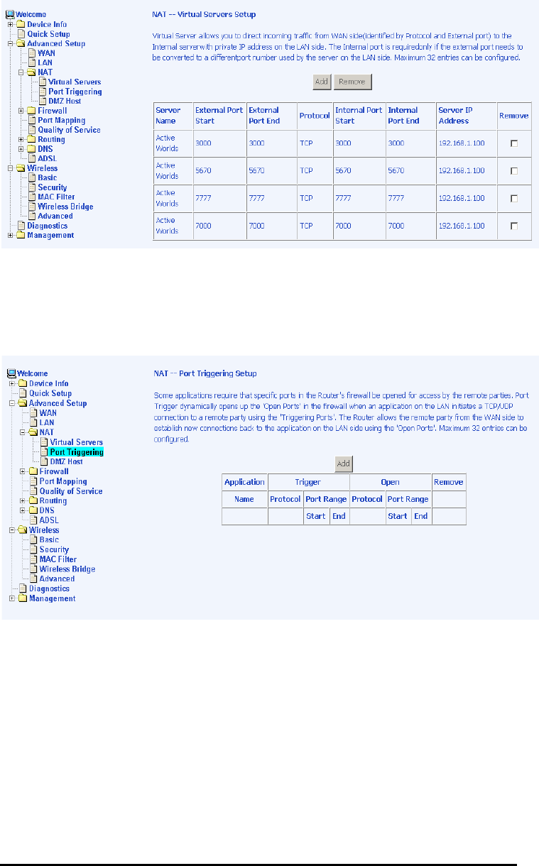
The following screen appears after you save your selection. To
add additional virtual servers, click on the Addd button. If you need
to remove any of the server names, select the check box and click
on the Removee button.
Port Triggering
Click on the Addd button to add Port Triggering to your Internet
application.
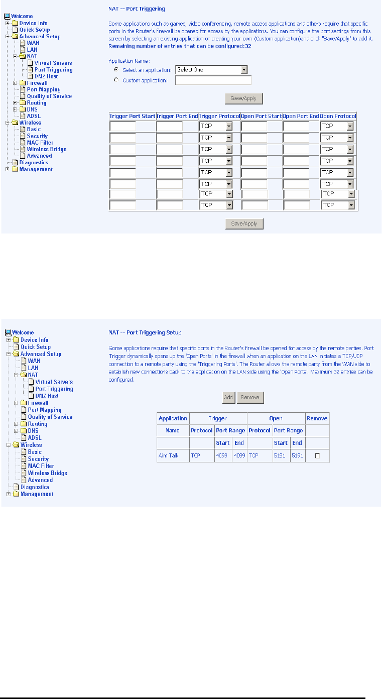
The below screen appears when you click on Addd allowing you to
select the application that you want to set the port settings for.
After a selection has been made, click on the Save / Apply button.
4-Port Wireless Ethernet Router
User Manual
29
Version 1.0
The below screen appears after you save your selections. You
will be able to add or remove selections made, by clicking on the
Addd and Removee buttons.
4-Port Wireless Ethernet Router
User Manual
30
Version 1.0
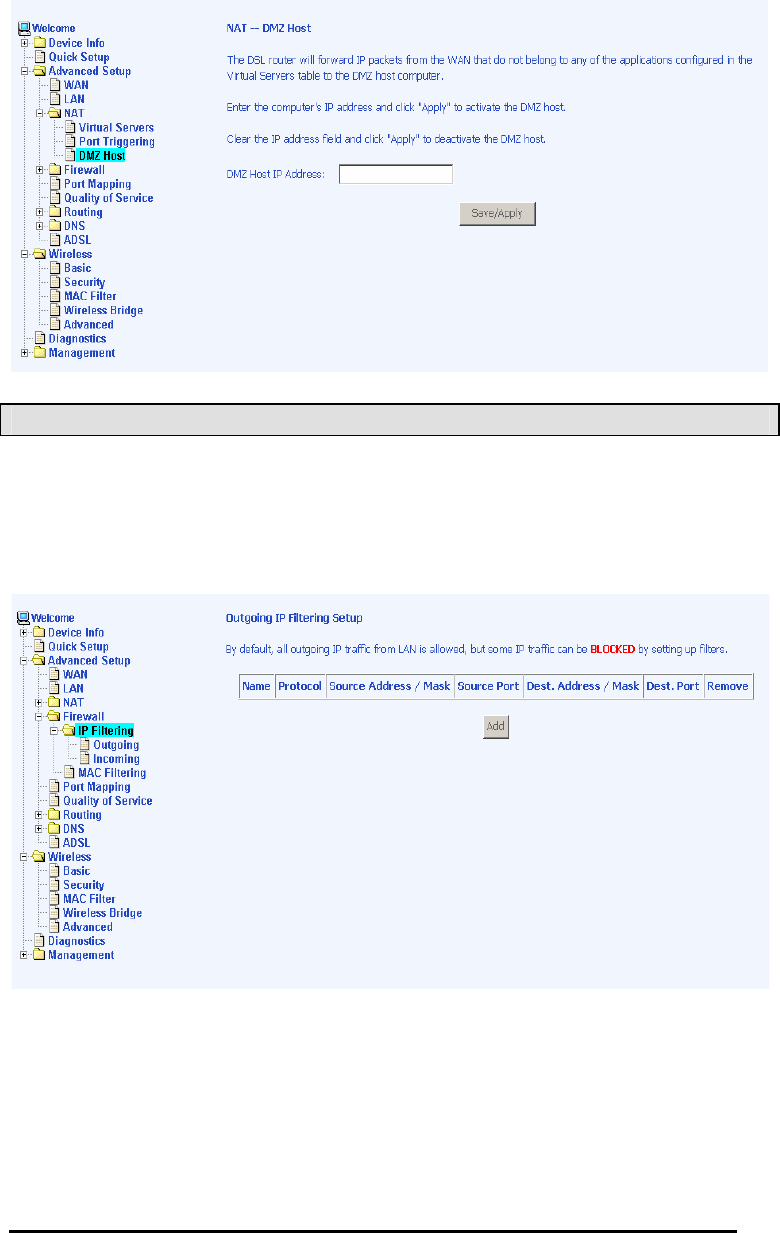
DMZ Host
You can define the IP address of the DMZ Host on this screen.
Enter the IP address and click on Save / Applyy.
Firewall
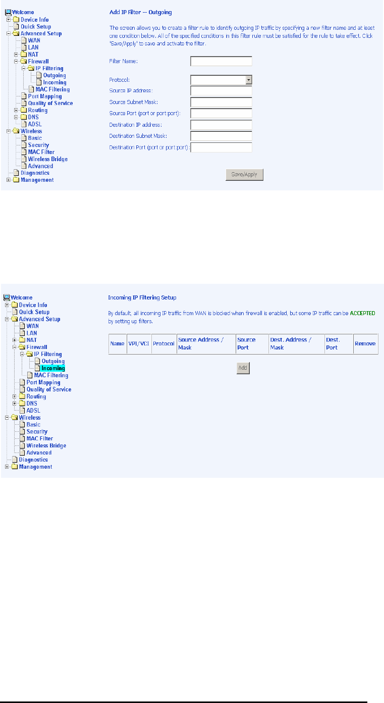
IP Filtering—Outgoing
The outgoing filter will block the LAN traffic from entering the
WAN side. Click on the Addd button to create filters.
The below screen will appear when you click on Addd. Input the
filter name, source information (from the LAN side), and
destination information (from the WAN side). Then click on Save /
Applyy.
4-Port Wireless Ethernet Router
User Manual
31
Version 1.0
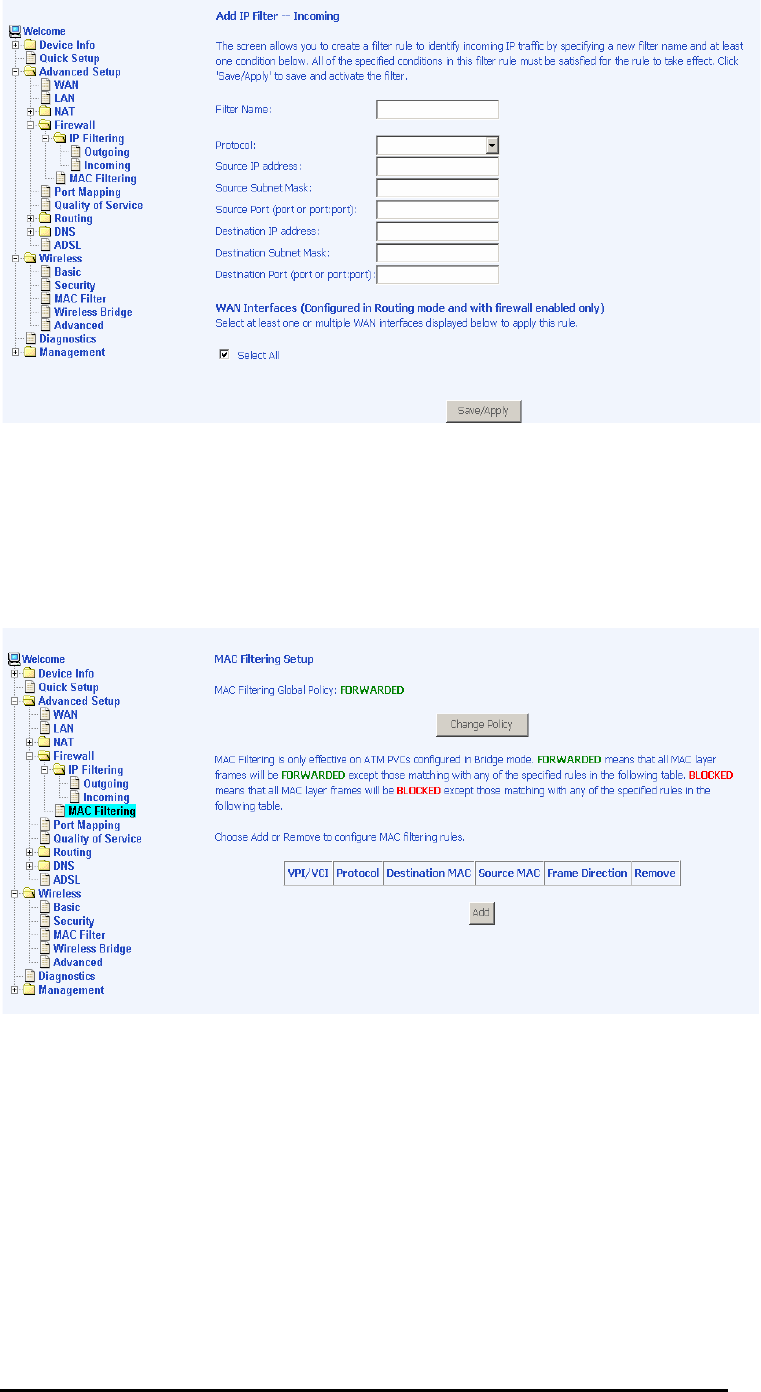
IP Filtering—Incoming
Incoming filter filters the WAN traffic to the LAN side. Click on the
Addd button to add incoming filter settings.
Enter a filter name, information about the source address (from
the WAN side), and information about the destination address (to
the LAN side). Select the protocol and WAN interface, then click
on Save/Applyy to add the setting.
You can view and delete the incoming filter settings from this
screen.
4-Port Wireless Ethernet Router
User Manual
32
Version 1.0
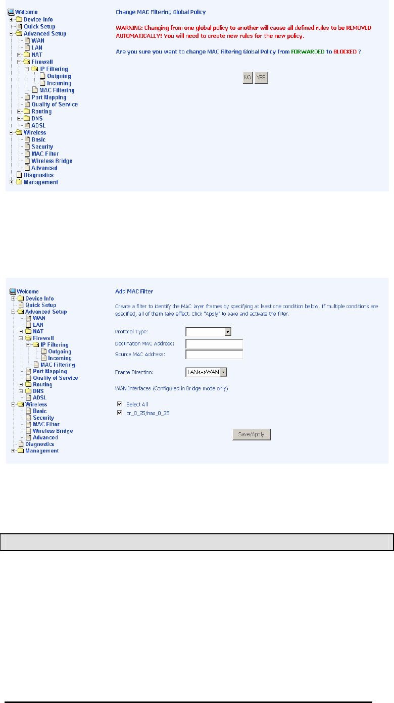
MAC Filtering
MAC filtering can forward or block traffic by MAC address. You
can change the policy or add settings to the MAC filtering table
using the MAC Filtering Setup screen.
If you click on Change Policyy, a confirmation dialog allows you to
verify your change.
4-Port Wireless Ethernet Router
User Manual
33
Version 1.0
If you want to add a setting to the MAC filtering table, enter the
Source and Destination MAC address, and select protocol type,
frame direction, and WAN interface. Then click on Save / Apply to
save it.
After you save the settings, a screen showing the settings will
appear. On this screen you will be able to view and delete MAC
filtering rules.
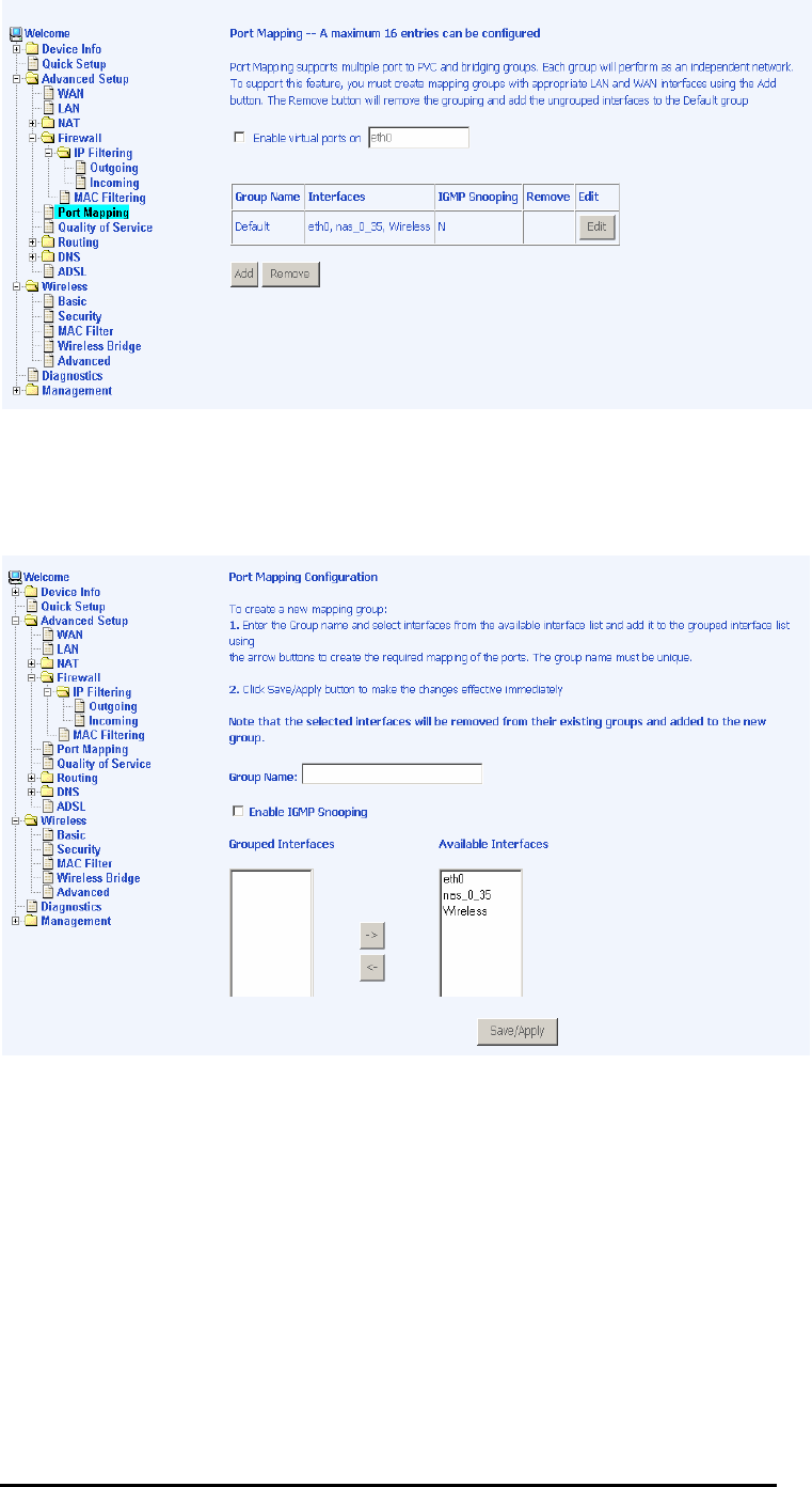
Port Mapping
Port mapping is a feature that allows you to open ports to allow
certain Internet applications on the WAN side to pass through the
firewall and enter your LAN. To use this feature, mapping groups
need to be created. To do this, follow the below instructions—
1. Click on the Addd button as displayed below.
4-Port Wireless Ethernet Router
User Manual
34
Version 1.0
2. After clicking the Addd button, the below configuration
screen appears, allowing you enter the groups and the
interfaces they are associated with.
4-Port Wireless Ethernet Router
User Manual
35
Version 1.0
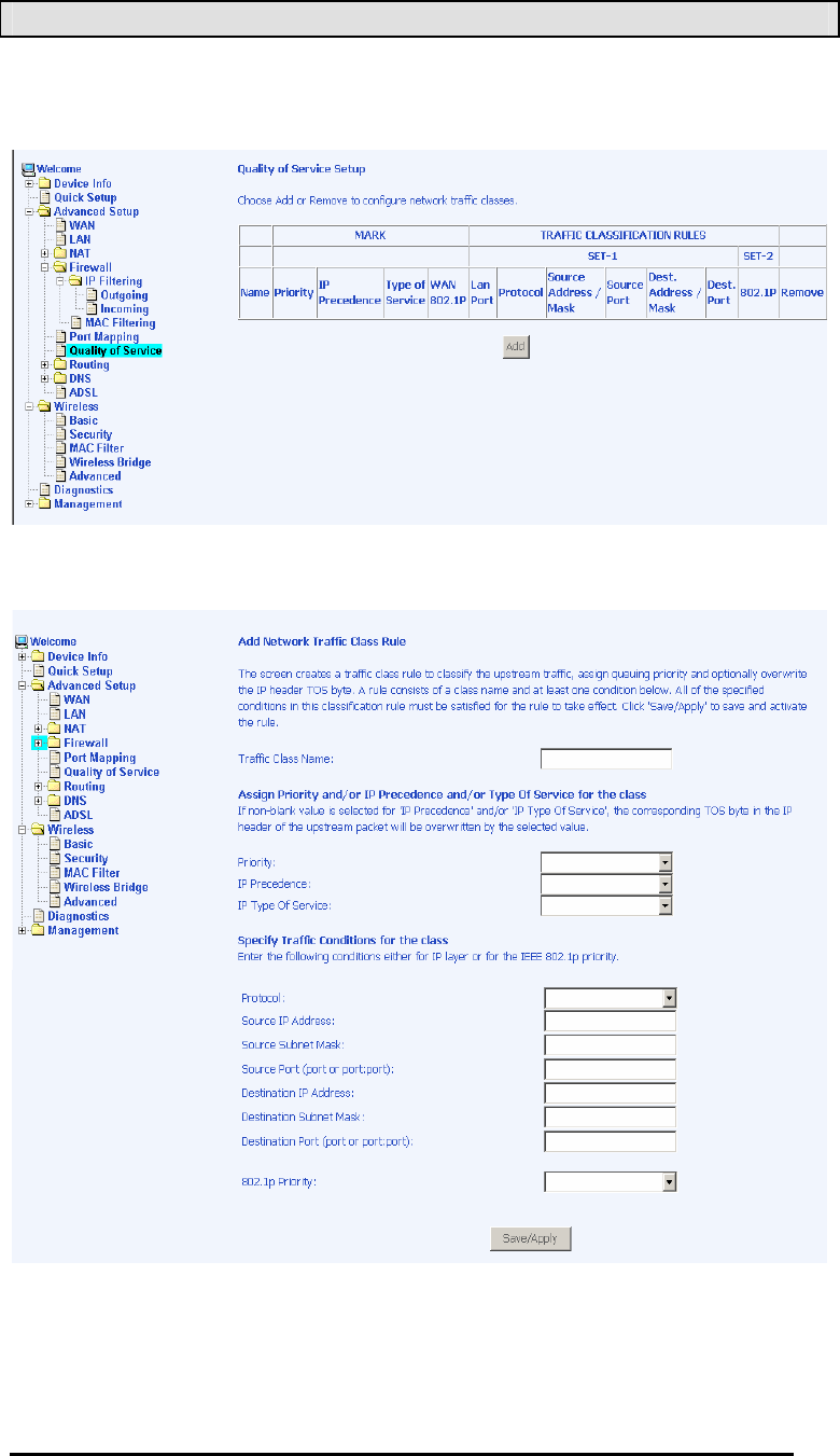
Quality of Service
You can configure the Quality of Service to apply different
priorities to traffic on the router.
On this screen you can view and delete QoS settings.
4-Port Wireless Ethernet Router
User Manual
36
Version 1.0
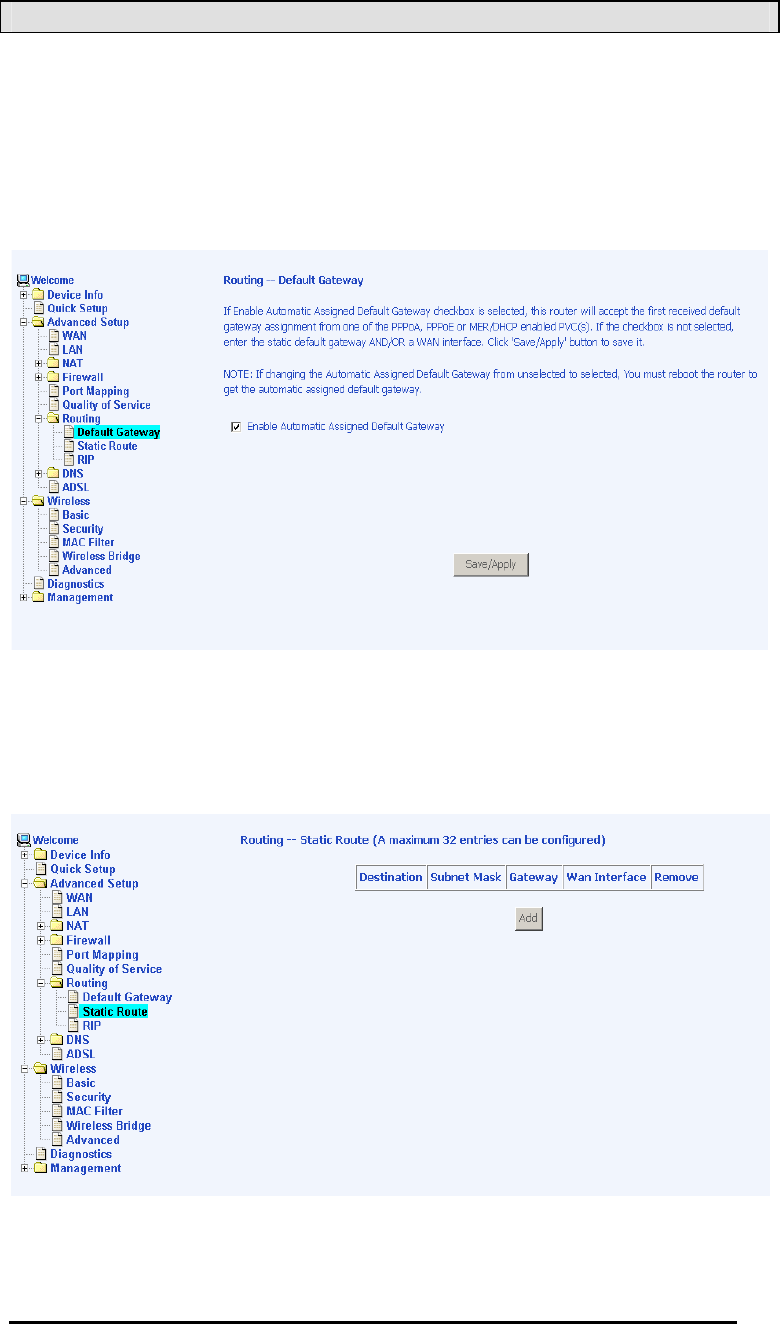
Routing
Default Gateway
You can enable automatic assigned default gateway on the
Routing – Default Gateway screen. As default, the box is checked
for automatic assigned default gateway to be enabled. Click the
Save / Apply button to enable or disable this feature.
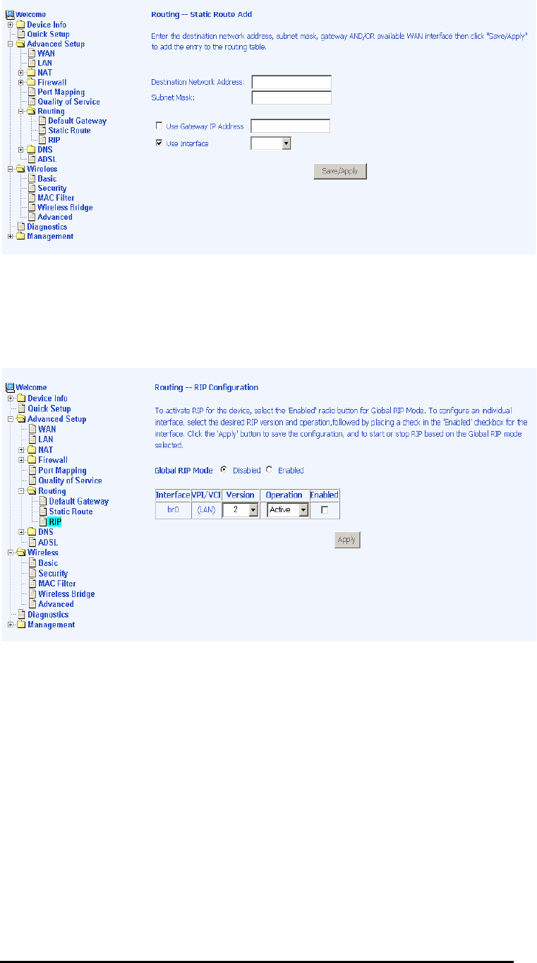
Static Route
Use the Routing – Static Route screen to add a static route to the
routing table.
Enter the route information and click on Save/Applyy to make it
active. No reboot is required.
4-Port Wireless Ethernet Router
User Manual
37
Version 1.0
RIP
If RIP is enabled, the router operation can be configured as active
or passive.
4-Port Wireless Ethernet Router
User Manual
38
Version 1.0
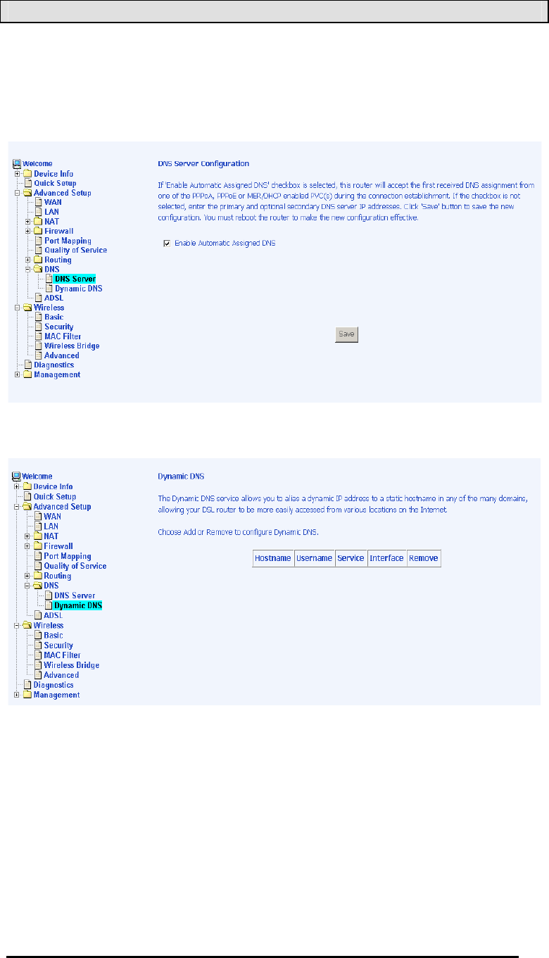
DNS
DNS Server
Use the DNS Server screen to request automatic assignment of a
DNS or to specify a primary and secondary DNS.
Dynamic DNS
4-Port Wireless Ethernet Router
User Manual
39
Version 1.0
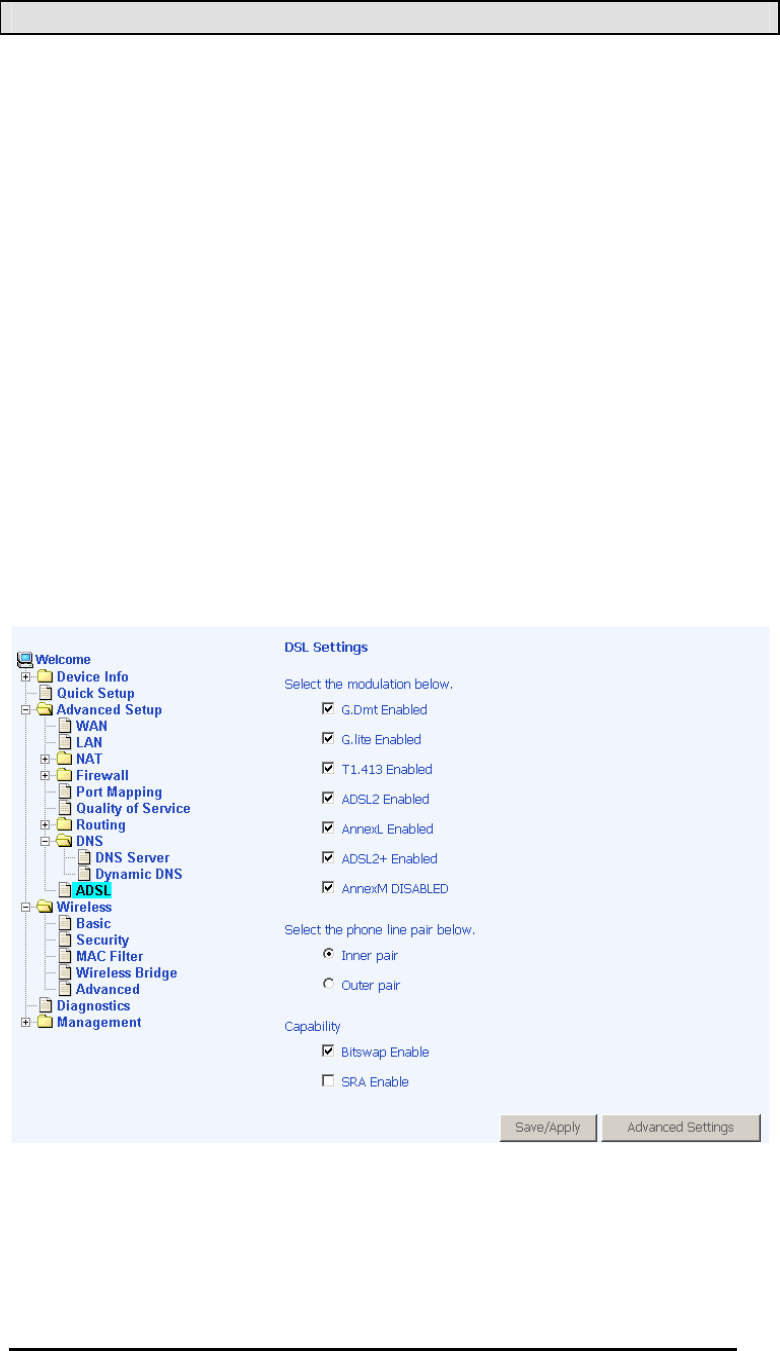
ADSL
There are three major items in the ADSL settings:
Modulation Methods
Six modulation methods for different linking speed are supported
by the 6211 ADSL router: G.Dmt Enabled, G.lite Enabled, T1.413
Enabled, ADSL Enabled, Annex L Enabled, and ADSL2+ Enabled.
Set this value only as directed by your ISP.
Phone Line Pair
The 6211 ADSL router supports phone lines on pins 2 and 3 or
pins 1 and 4 to connect your ADSL line. If your phone system
uses pins 2 and 3, attach a normal RJ11 cable to the router and
select “ Inner pair” on the screen; if your phone system uses pins 1
and 4, attach the phone with the supplied RJ11 cable and select
“ Outer pair” on the screen.
Capability
Do not change these settings unless directed by your ISP.
4-Port Wireless Ethernet Router
User Manual
40
Version 1.0
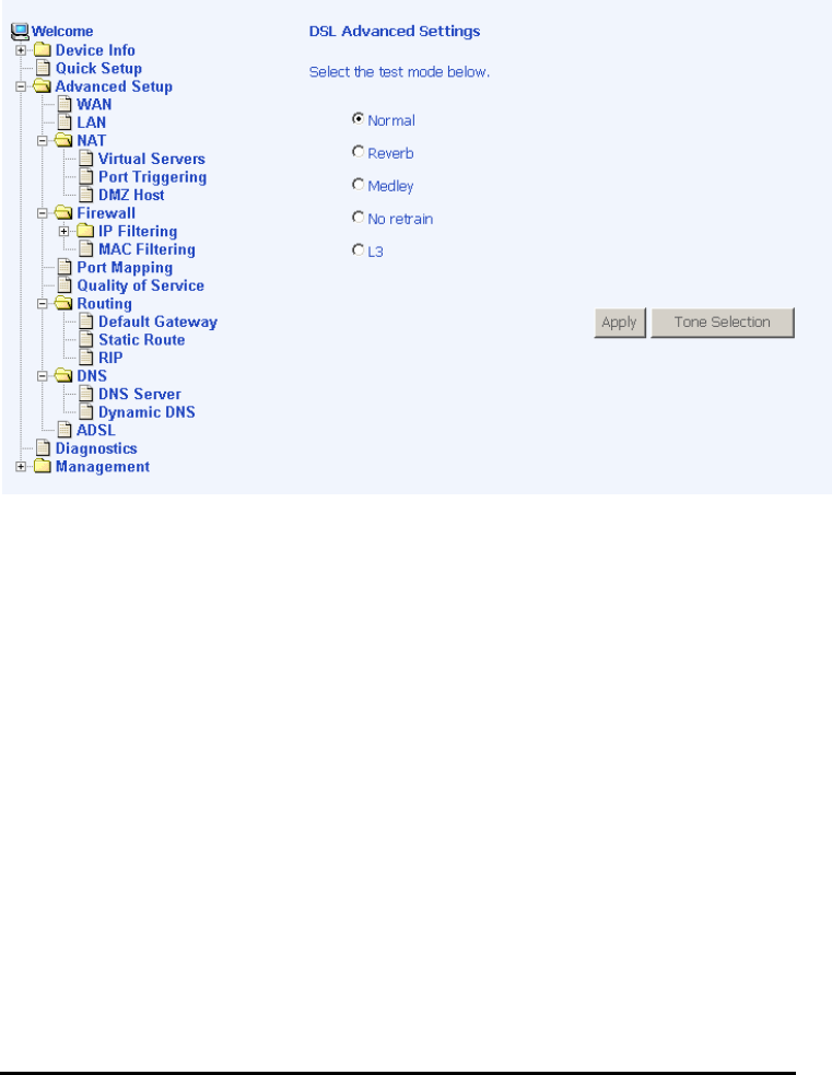
DSL Advanced Settings
The test mode can be selected from the DSL Advanced Settings
page.
Test modes are as follows—
•Normal
•Reverb
•Medley
•No retrain
•L3
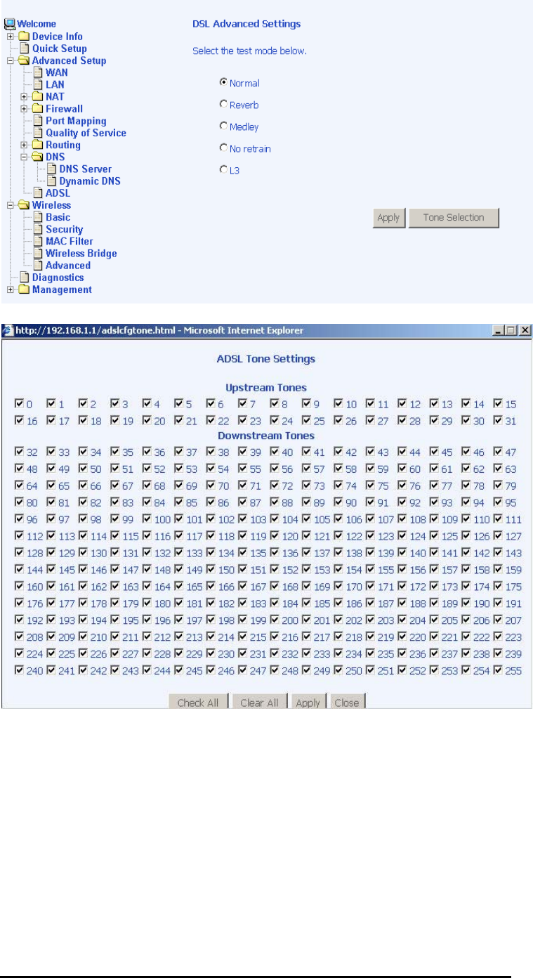
Tone Settings
The frequency band of ADSL is split up into 256 separate tones,
each spaced 4.3125 kHz apart. With each tone carrying separate
data, the technique operates as if 256 separate modems were
running in parallel. The tone range is from 0 to 31 for upstream
and from 32 to 255 for downstream. Do not change these settings
unless so directed by your ISP.
4-Port Wireless Ethernet Router
User Manual
41
Version 1.0
4-Port Wireless Ethernet Router
User Manual
42
Version 1.0
Wireless
This section allows you to configure wireless settings on your
router.
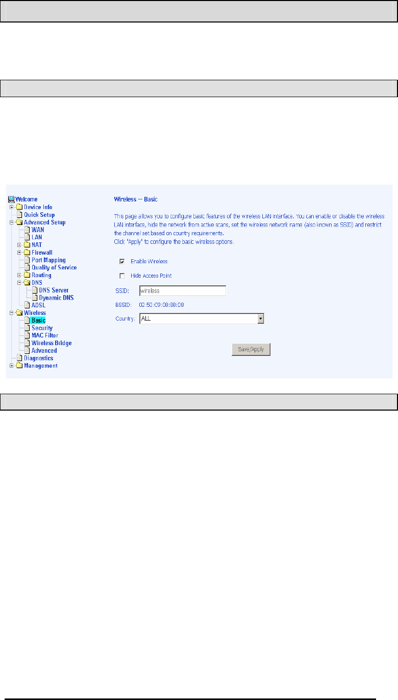
Basic
The below Wireless – Basic screen lets you enable or disable
wireless. The default setting for wireless is enabled. You can
also hide the access point so others cannot see your ID on the
network.
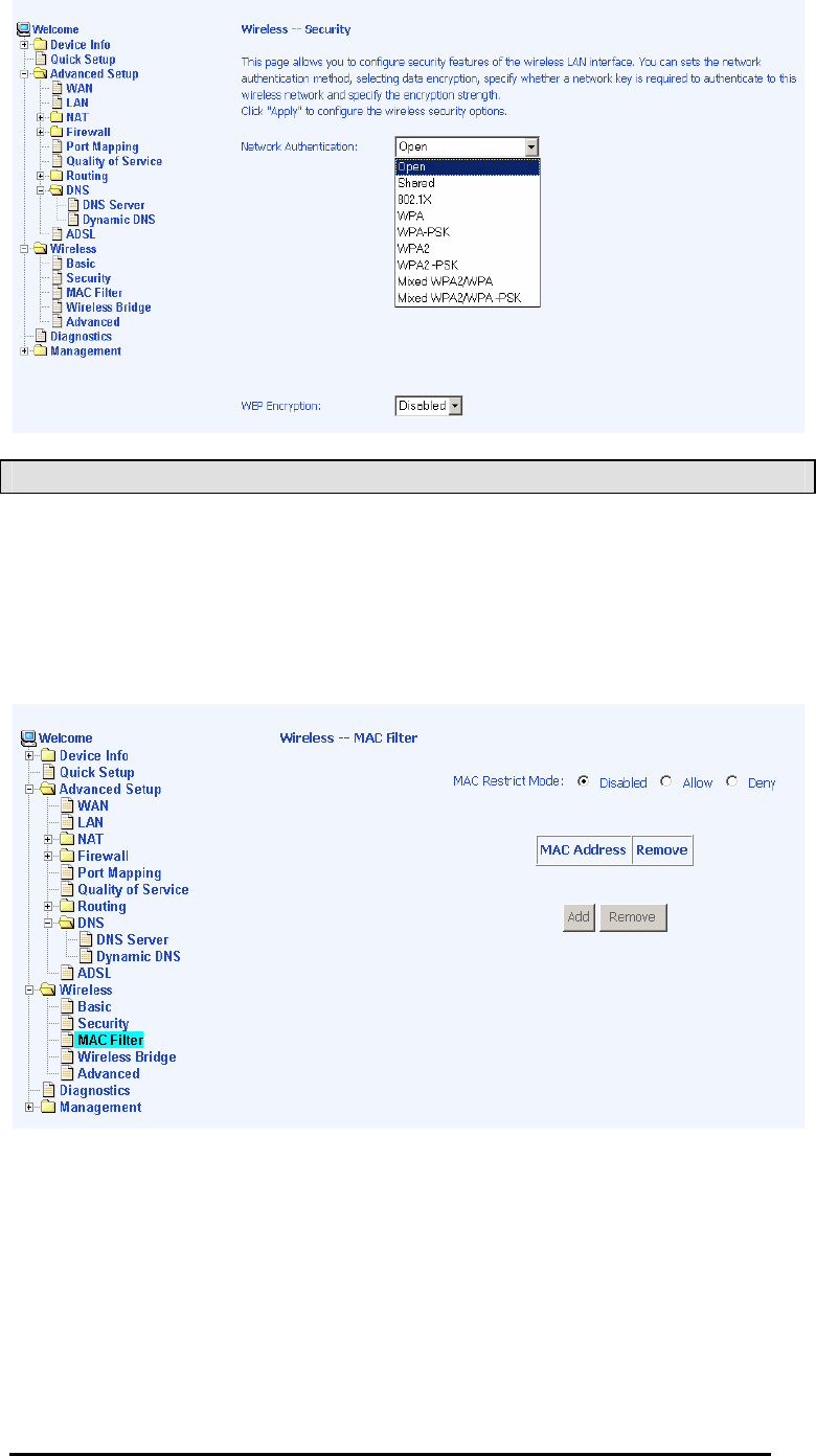
Security
The next screen is the Wireless – Securityy screen which allows
you to select the network authentication method and to enable or
disable WEP encryption. Note that depending on the network
authentication that is selected, the screen will change accordingly
so additional fields can be configured for the specific
authentication method.
Network authentication methods include the following—
•Openn—anyone can access the network. The default is a
disabled WEP encryption setting.
•Sharedd—WEP encryption is enabled and encryption key
strength of 64-bit or 128-bit needs to be selected. Click on
Set Encryption Keys to manually set the network encryption
keys. Up to 4 different keys can be set and you can come
back to select which one to use at anytime.

4-Port Wireless Ethernet Router
User Manual
43
Version 1.0
•802.1X——requires mutual authentication between a client
station and the router by including a RADIUS-based
authentication server. Information about the RADIUS
server such as its IP address, port and key must be entered.
WEP encryption is also enabled and the encryption
strength must also be selected.
•WPA—(Wi-Fi Protected Access))— usually used for the larger
Enterprise environment, it uses a RADIUS server and TKIP
(Temporal Key Integrity Protocol) encryption (instead of
WEP encryption which is disabled). TKIP uses128-bit
dynamic session keys (per user, per session, and per
packet keys).
•WPA-PSK (Wi-Fi Protected Access – Pre-Shared Key))—
WPA for home and SOHO environments also using the
same strong TKIP encryption, per-packet key construction,
and key management that WPA provides in the enterprise
environment. The main difference is that the password is
entered manually. A group re-key interval time is also
required.
•WPA2 (Wi-Fi Protected Access 2)) —second generation of
WPA which uses AES (Advanced Encryption Standard)
instead of TKIP as its encryption method. Network re-auth
interval is the time in which another key needs to be
dynamically issued.
•WPA2-PSK (Wi-Fi Protected Access 2 – Pre-Shared Key))—
suitable for home and SOHO environments, it also uses
AES encryption and requires you to enter a password and
an re-key interval time.
•Mixed WPA2 / WPAA—during transitional times for upgrades
in the enterprise environment, this mixed authentication
method allows “ upgraded” and users not yet “ upgraded” to
access the network via the router. RADIUS server
information must be entered for WPA and a as well as a
group re-key interval time. Both TKIP and AES are used.
•Mixed WPA2 / WPA-PSKK—useful during transitional times
for upgrades in the home or SOHO environment, a pre-
shared key must be entered along with the group re-key
interval time. Both TKIP and AES are also used.
4-Port Wireless Ethernet Router
User Manual
44
Version 1.0
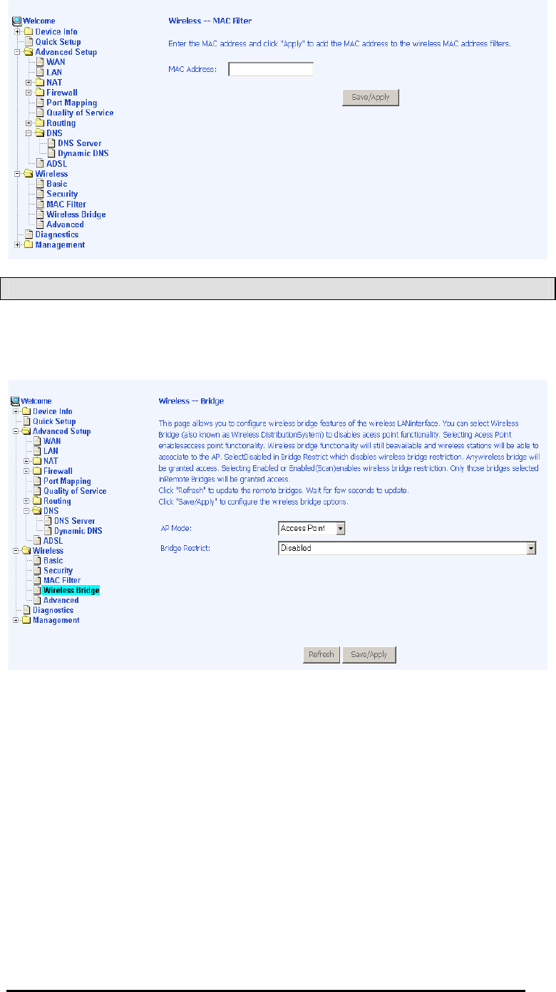
MAC Filter
The MAC filter screen allows you to manage MAC address filters.
Add the MAC addresses that you want to manage and then select
the mode that you want to use to manage them. You can disable
this feature or you can allow or deny access to the MAC
addresses that you add to the list.
The following screen appears when you want to add a MAC
address to the filter. When completed, click on the Save / Apply
button.
4-Port Wireless Ethernet Router
User Manual
45
Version 1.0
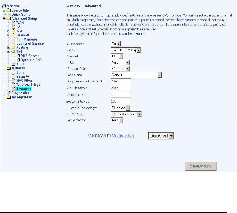
Wireless Bridge
In this next screen, you can select which mode you want the
router to be in, either access point or wireless bridge.

4-Port Wireless Ethernet Router
User Manual
46
Version 1.0
Advanced
Advanced features of the wireless LAN interface can be
configured in this section.
Settings can be configured for the following—
•AP Isolationn—if you select enable, then each of your
wireless clients will not be able to communicate with each
other.
•Bandd—a default setting at 2.4GHz – 802.11g
•Channell-- 802.11b and 802.11g use channels to limit
interference from other devices. If you are experiencing
interference with another 2.4Ghz device such as a baby
monitor, security alarm, or cordless phone, then change the
channel on your router.
•Multicast Ratee—the rate at which a message is sent to a
specified group of recipients.
•Basic Ratee—the set of data transfer rates that all the
stations will be capable of using to receive frames from a
wireless medium.
•Fragmentation Thresholdd—used to fragment packets which
help improve performance in the presence of radio
frequency (RF) interference.
•RTS Threshold (Request to Send Threshold)) —determines
the packet size of a transmission through the use of the
router to help control traffic flow.
•DTIM Intervall—sets the Wake-up interval for clients in
power-saving mode.
•Beacon Intervall—a packet of information that is sent from a
connected device to all other devices where it announces
its availability and readiness. A beacon interval is a period
of time (sent with the beacon) before sending the beacon
again. The beacon interval may be adjusted in milliseconds
(ms).
4-Port Wireless Ethernet Router
User Manual
47
Version 1.0
•Xpress Technology——a technology that utilizes standards
based on framebursting to achieve higher throughput. With
Xpress Technology enabled, aggregate throughput (the
sum of the individual throughput speeds of each client on
the network) can improve by up to 25% in 802.11g only
networks and up to 75% in mixed networks comprised of
802.11g and 802.11b equipment.
•54g Mode—— 54g is a Broadcom Wi-Fi technology.
•54g Protectionn--the 802.11g standards provide a protection
method so 802.11g and 802.11b devices can co-exist in the
same network without “ speaking” at the same time. Do not
disable 54g Protection if there is a possibility that a 802.11b
device may need to use your wireless network. In Auto
Mode, the wireless device will use RTS/CTS (Request to
Send / Clear to Send) to improve 802.11g performance in
mixed 802.11g/802.11b networks. Turn protection off to
maximize 802.11g throughput under most conditions.
•WMM (Wi-Fi Multimedia)) —feature that improves the your
experience for audio, video and voice applications over a
Wi-Fi network.
4-Port Wireless Ethernet Router
User Manual
48
Version 1.0
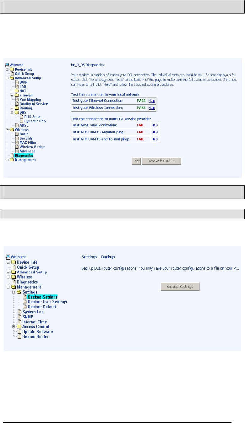
Troubleshooting—Diagnostics
The diagnostics screen allows you to run diagnostic tests to check
your DSL connection. In addition, you can test the connection to
your DSL service provider.
Management
Settings
Backup Settings
4-Port Wireless Ethernet Router
User Manual
49
Version 1.0
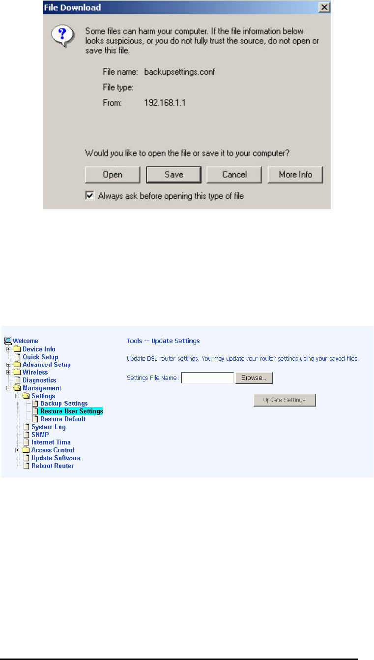
Restore User Settings
To restore saved settings, select
Management Settings Restore User Settings .ШШ
Select the backup file you want to restore and click on Update
Settingss.
The router will restore settings and reboot to activate the restored
settings.
4-Port Wireless Ethernet Router
User Manual
50
Version 1.0
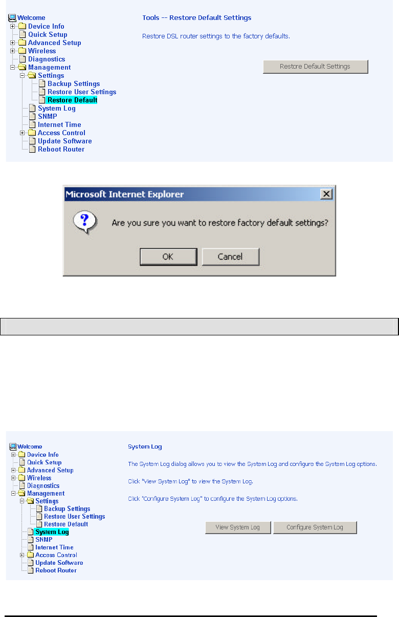
Restore Default
Restore Default will erase all current settings and restore the
router to factory default settings. To restore the router to factory
default settings, select Management Settings Restore Default.ШШ
Reply OK to the confirmation dialog.
The router will restore the default settings and reboot.
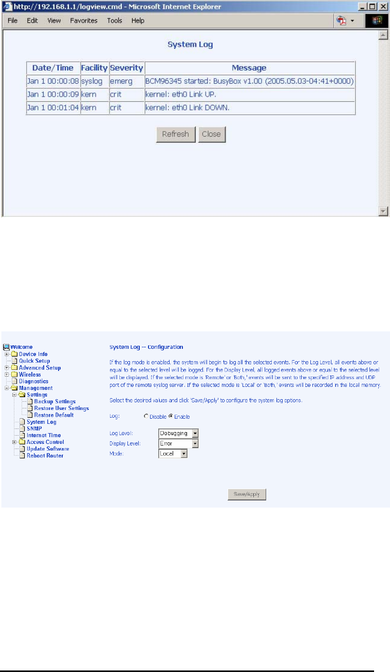
System Log
The System Log dialog allows you to view the System Log and
configure the System Log options.
To view the System Log click on the View System Logg button to
check the log file.
4-Port Wireless Ethernet Router
User Manual
51
Version 1.0
Below is a view of the System Logg.
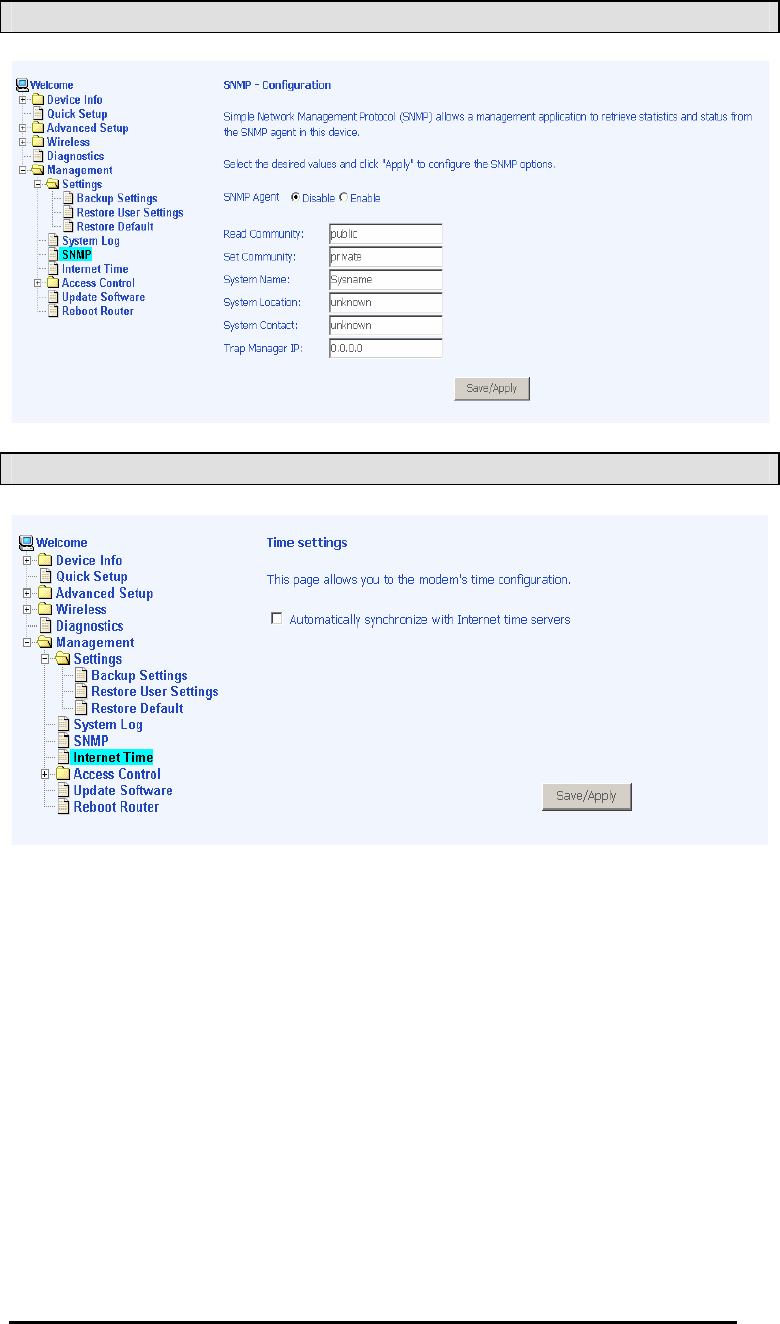
Configure System Log
If the log is enabled, the system will log selected events:
Emergency, Alert, Critical, Error, Warning, Notice, Informational,
and Debugging. All events above or equal to the selected log
level will be logged and displayed.
If the selected mode is “ Remote” or “ Both” , events will be sent to
the specified IP address and UDP port of a remote system log
server. If the selected mode is “ Local” or “ Both” , events will be
recorded in the local memory. Select the desired values and click
on the “Save/Applyy” button to configure the system log options.
4-Port Wireless Ethernet Router
User Manual
52
Version 1.0
SNMP
Internet Times
4-Port Wireless Ethernet Router
User Manual
53
Version 1.0
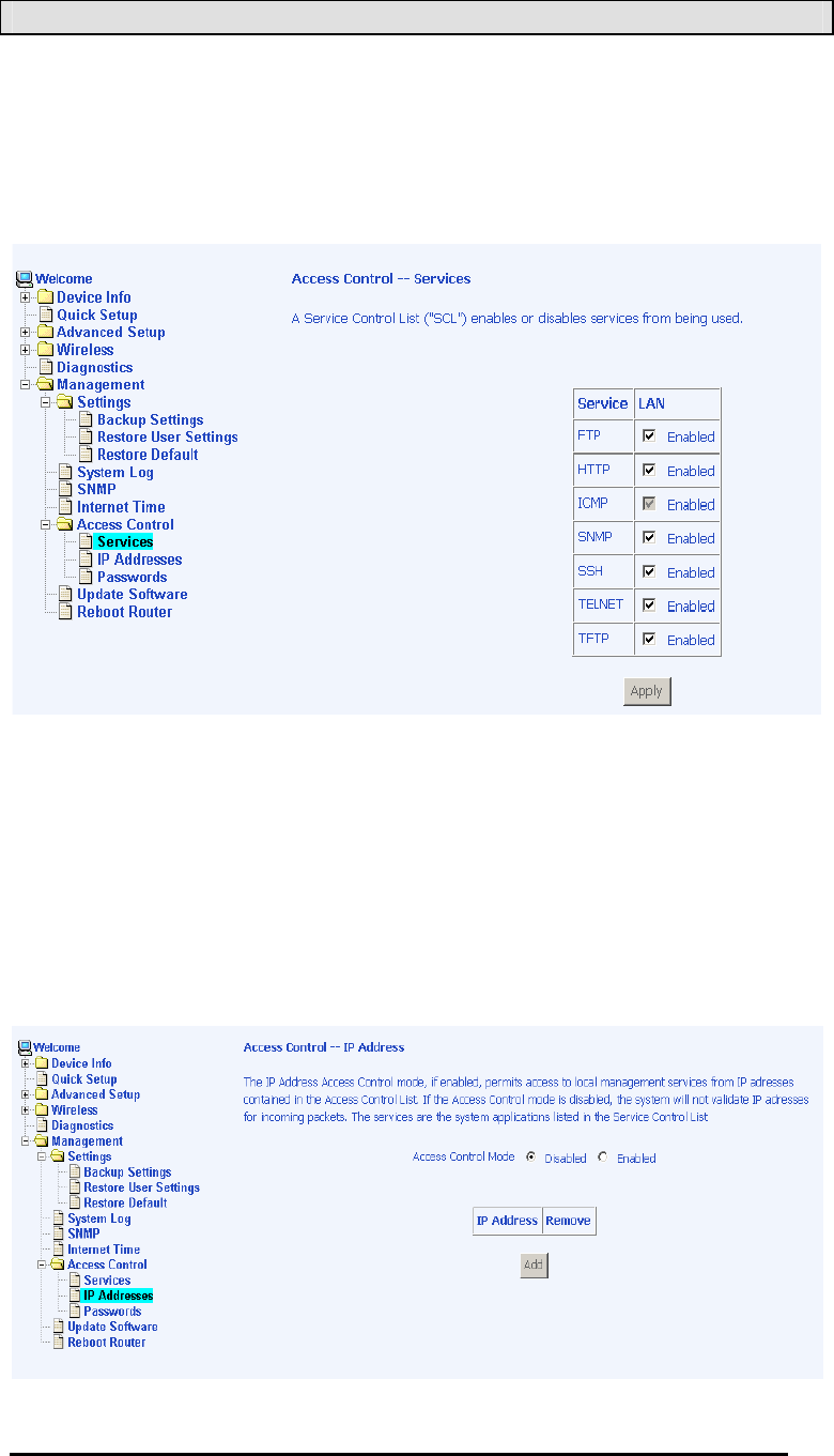
Access Control
You can enable or disable some services of your router by LAN or
WAN. If no WAN connection is defined, only the LAN side can be
configured.
Services
IP Addresses
Web access to the router can be limited when Access Control
Mode is enabled. The IP addresses of allowed hosts can be
added using Access Control IP Address.Ш
Add the IP address to the IP address list by clicking on the Add
button, then select “Enabledd” to enable Access Control Mode.
4-Port Wireless Ethernet Router
User Manual
54
Version 1.0
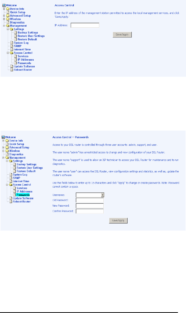
To assign the IP address of the management station that is
permitted to access the local management services, enter the IP
address in the box and click on the Save / Apply button.
Passwords
Access the Passwordss screen under the Access Controll section
to change a password. Select an account and enter the current
password and the new password and then click on the Save /
Applyy button.
4-Port Wireless Ethernet Router
User Manual
55
Version 1.0
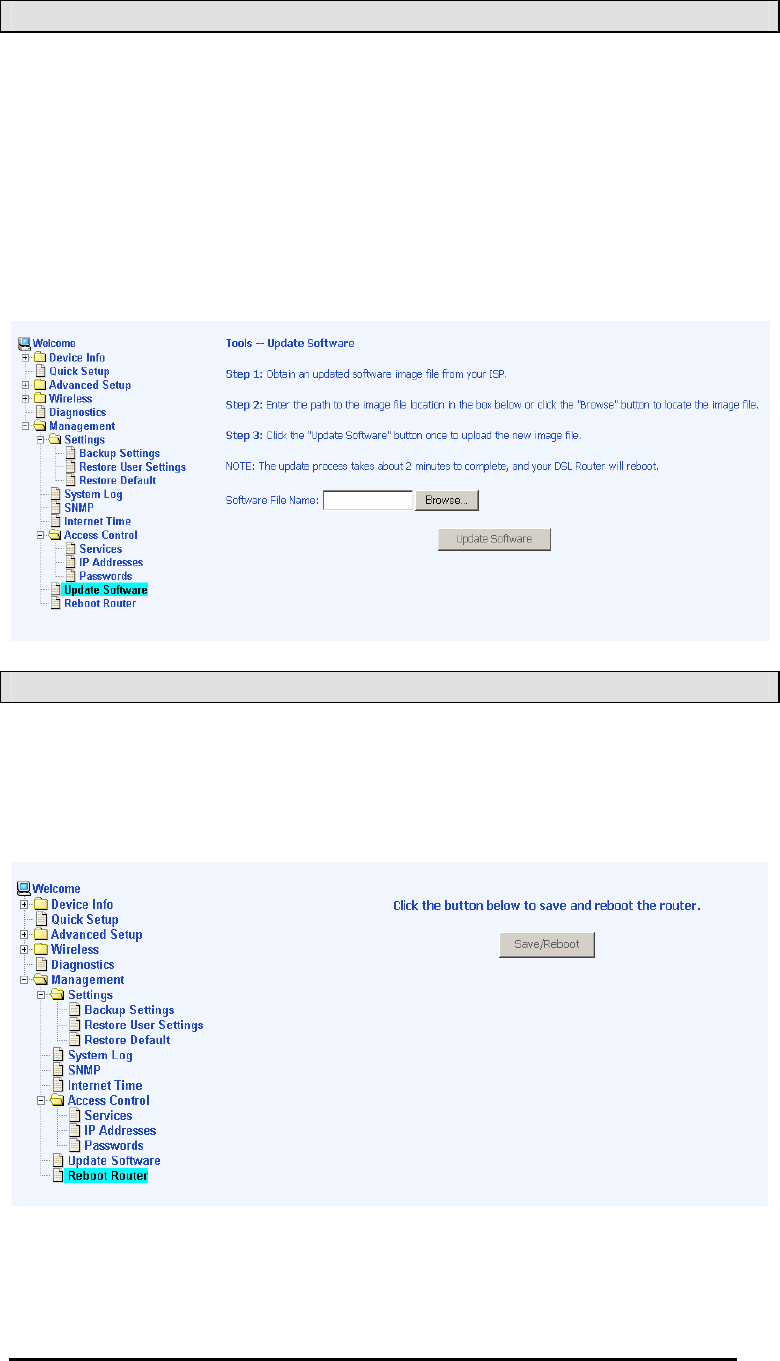
Update Software
If your ISP releases new software for this router, follow these
steps to perform an upgrade.
1. Obtain an updated software image file from your ISP.
2. Enter the path to the image file location or click on the Browse
button to locate the image file.
3. Click the Update Softwaree button once to upload the new
image file.
Reboot Router
Select Management Reboot Router to reboot the router usingШ
the web interface. The router will save the current configuration
and reboot itself using the new configuration.

4-Port Wireless Ethernet Router
User Manual
56
Version 1.0
Appendix
FCC Warning Statement
This device complies with Part 15 of the FCC Rules. Operation is
subject to the following two conditions:
(1) this device may not cause harmful interference, and
(2) this device must accept any interference received, including
interference that may cause undesired operation.
This equipment has been tested and found to comply with the
limits for a class B digital device, pursuant to part 15 of the FCC
Rules. These limits are designed to provide reasonable protection
against harmful interference in a residential installation.
This equipment generates, uses and can radiate radio frequency
energy and, if not installed and used in accordance with the
instructions, may cause harmful interference to radio
communications. However, there is no guarantee that interference
will not occur in a particular installation. If this equipment does
cause harmful interference to radio or television reception, which
can be determined by turning the equipment off and on, the user
is encouraged to try to correct the interference by one or more of
the following measures:
ЁReorient or relocate the receiving antenna.
ЁIncrease the separation between the equipment and receiver.
ЁConnect the equipment into an outlet on a circuit different from
that to which the receiver is connected.
ЁConsult the dealer or an experienced radio/TV technician for
help.
Any changes or modifications not expressly approved by the party
responsible for compliance could void the user’s authority to
operate the equipment.
This device and its antenna(s) must not be co-located or
operating in conjunction with any other antenna or transmitter
To maintain compliance with FCC’s RF exposure guidelines, this
equipment should be installed and operated with minimum
distance 20cm between the radiator and your body. Use on the
supplied antenna.

4-Port Wireless Ethernet Router
User Manual
57
Version 1.0
Declaration of Conformity for R&TTE directive 1999/5/EC
Essential requirements – Article 3
Protection requirements for health and safety – Article 3.1a
Testing for electric safety according to EN 60950-1 has been
conducted. These are considered relevant and sufficient.
Protection requirements for electromagnetic compatibility – Article
3.1b
Testing for electromagnetic compatibility according to EN 301
489-1 and EN 301 489-17 has been conducted. These are
considered relevant and sufficient.
Effective use of the radio spectrum – Article 3.2
Testing for radio test suites according to EN 300 328 has been
conducted. These are considered relevant and sufficient.
CE Mark Warning
This is a Class B product, in a domestic environment, this product
may cause radio interference, in which case the user may be
required to take adequate measures.