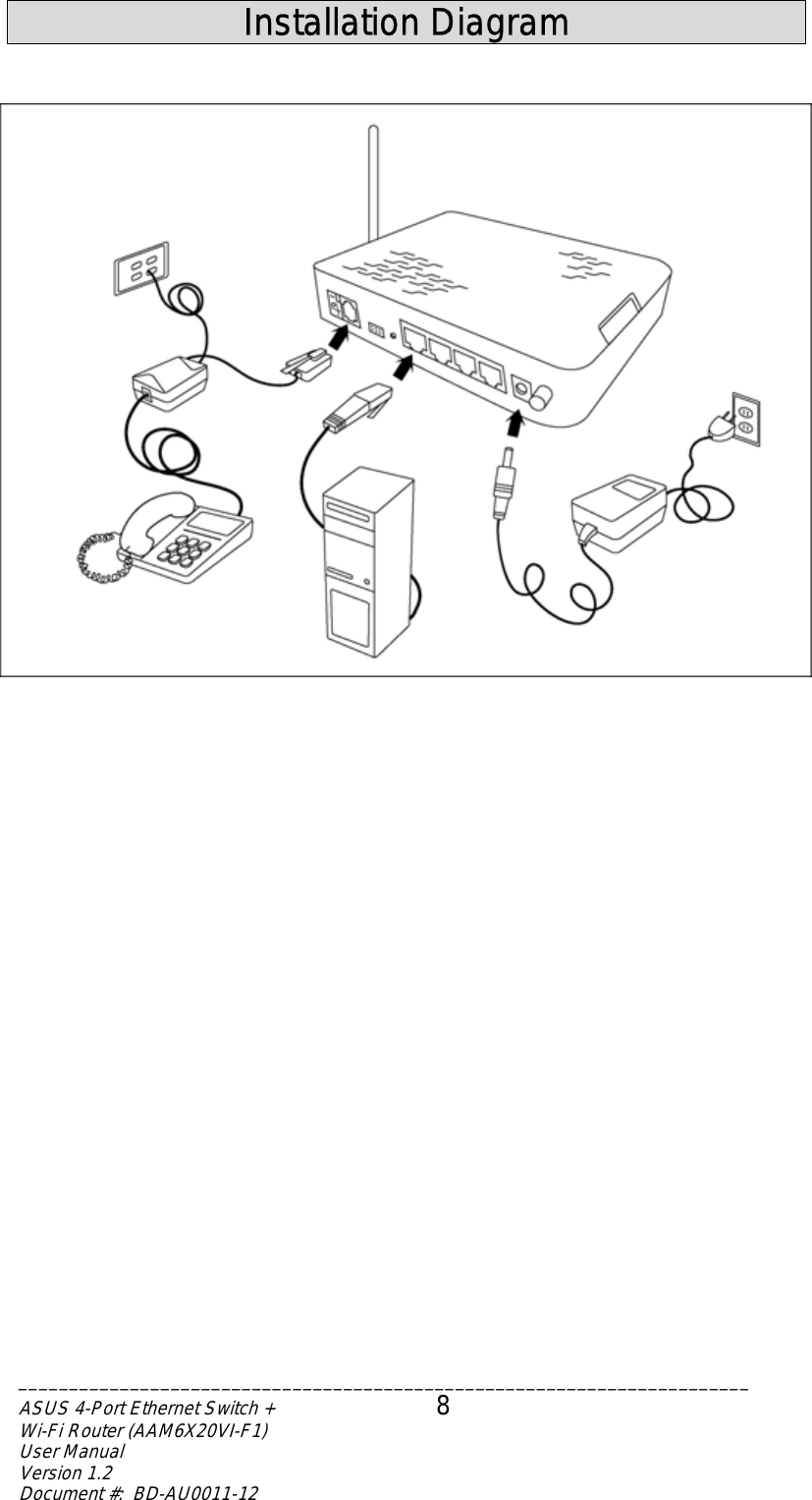
ASUSTeK Computer AAM6KVIF1 4-PORT ETHERNET SWITCH + WI-FI ADSL ROUTER User Manual 4 Port Ethernet Switch Wi Fi Router
ASUSTeK Computer Inc 4-PORT ETHERNET SWITCH + WI-FI ADSL ROUTER 4 Port Ethernet Switch Wi Fi Router
UserManual.wiki
>
ASUSTeK Computer
>
AAM6KVIF1 User Manual
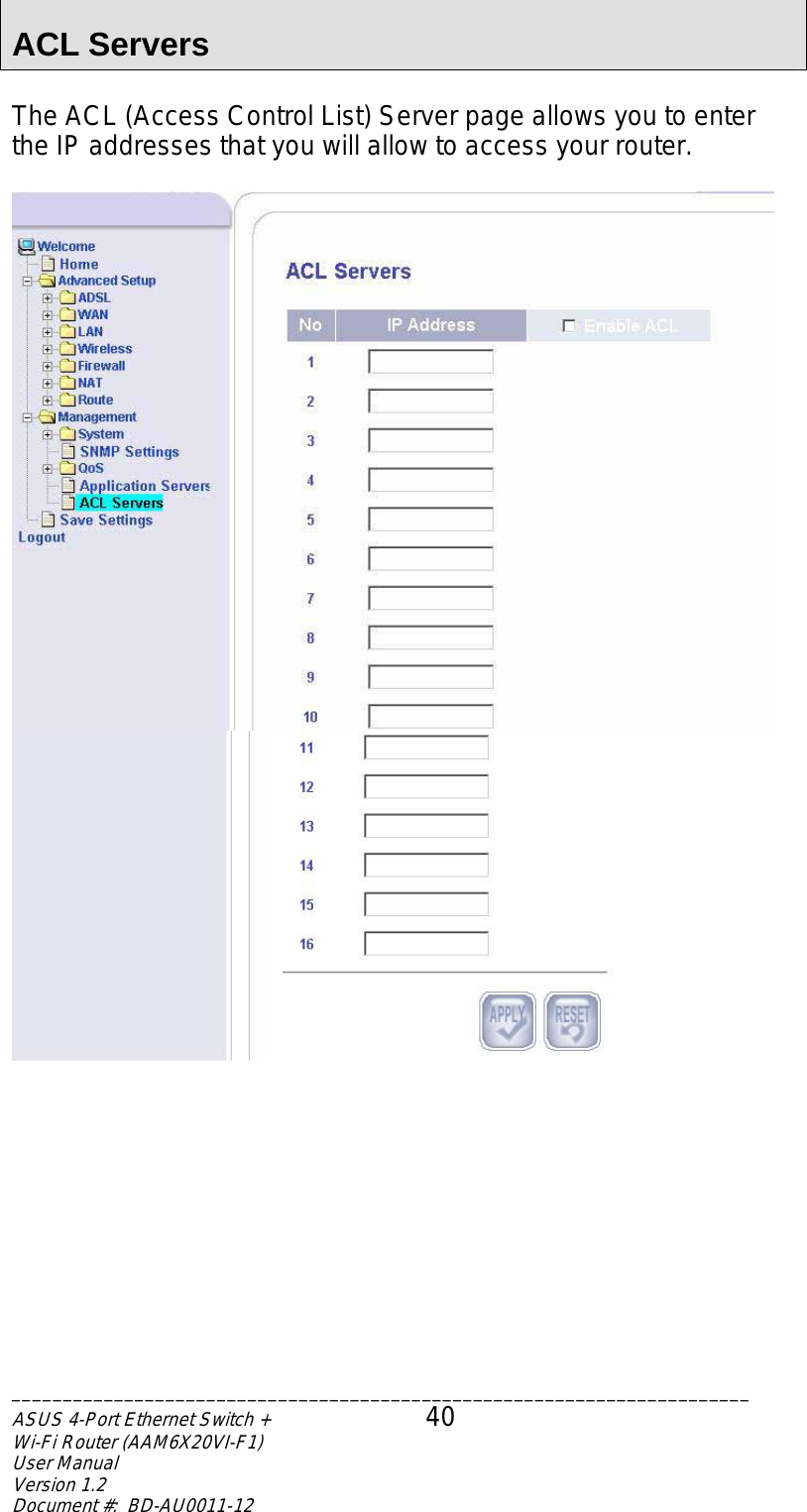
USERS MANUAL
Navigation menu
Upload a User Manual
Namespaces
Wiki Guide
HTML
PDF
Info
Views
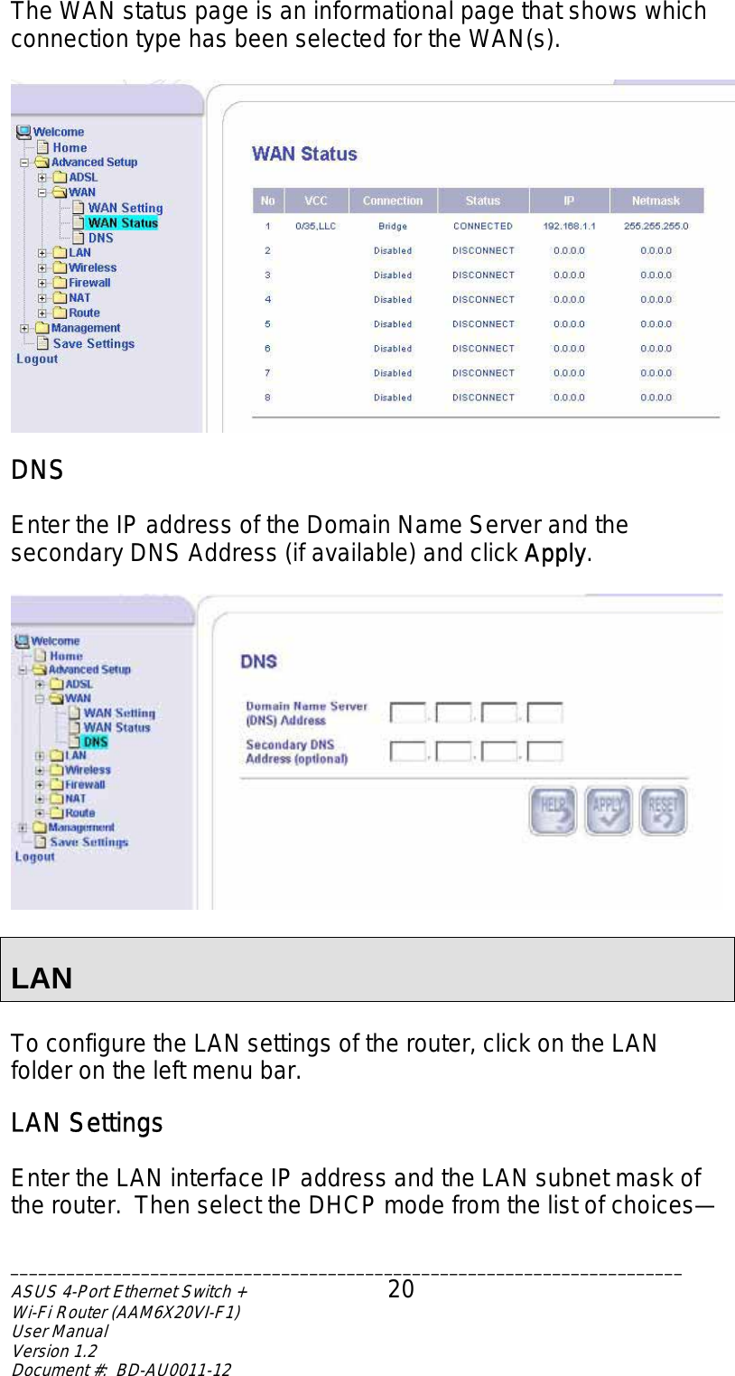
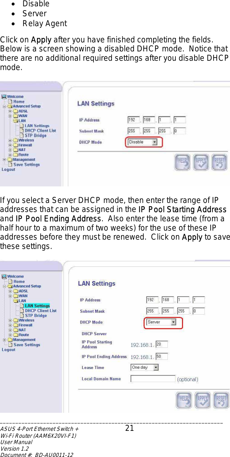
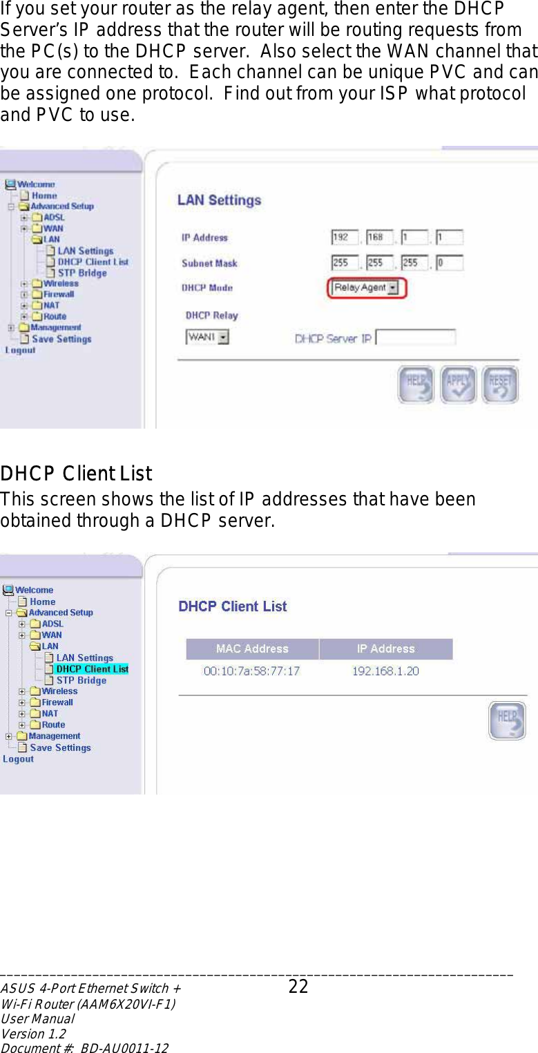
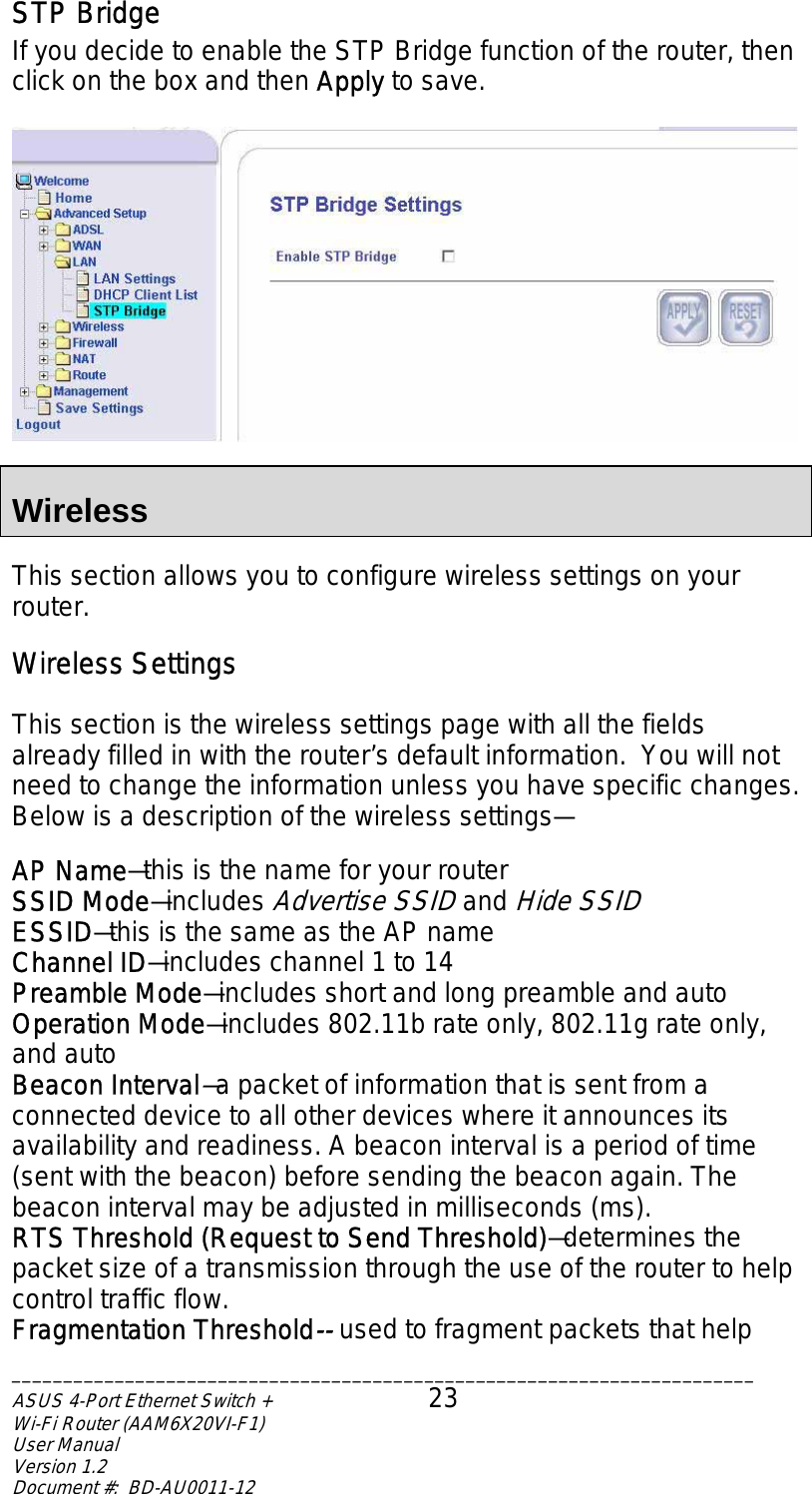
User Manual
Discussion / Help
Navigation