ASUSTeK Computer AAM6KVIF1 4-PORT ETHERNET SWITCH + WI-FI ADSL ROUTER User Manual 4 Port Ethernet Switch Wi Fi Router
ASUSTeK Computer Inc 4-PORT ETHERNET SWITCH + WI-FI ADSL ROUTER 4 Port Ethernet Switch Wi Fi Router
USERS MANUAL

4-Port Ethernet Switch +
Wi-Fi Router
AAM6X20VI-F1
User Manual
Version 1.2
Version Date: October 4, 2005
Document #: BD-AU0011-12
________________________________________________________________________
ASUS 4-Port Ethernet Switch +
1
Wi-Fi Router (AAM6X20VI-F1)
User Manual
Version 1.2
Document #: BD-AU0011-12
Revision Documentation
9/15/05 Version 1.1 shows changes for upgraded firmware to version 1.5.34.2-0-
1.1.3.6.0.2-GEN-0-EW-16.2
10/4/05 Version 1.2 includes a section on how to mount the router (p.9).

________________________________________________________________________
ASUS 4-Port Ethernet Switch +
2
Wi-Fi Router (AAM6X20VI-F1)
User Manual
Version 1.2
Document #: BD-AU0011-12
Table of Contents
GENERAL INFORMATION...............................................................4
Package Contents..................................................................4
Safety Ins ruc ions—Please read.t t
r...........................................4
F ont Panel View....................................................................5
Back Panel View ....................................................................6
INSTALLING THE ROUTER .............................................................7
Connect the ADSL Line and Telephone.................................7
Connect the PC to the Router................................................7
Connect the Power Adapter...................................................7
INSTALLATION DIAGRAM...............................................................8
MOUNTING THE ROUTER ..............................................................9
CONFIGURING YOUR COMPUTER................................................10
Windows 2000......................................................................10
Windows XP.........................................................................11
LOG IN TO THE ROUTER..............................................................12
HOME SCREEN ..........................................................................13
ADVANCED SETUP .....................................................................14
ADSL..........................................................................................14
ADSL Status.........................................................................14
ADSL Configuration .............................................................15
OAM Configuration...............................................................16
WAN...........................................................................................16
WAN Settings.......................................................................17
WAN Status..........................................................................19
DNS......................................................................................20
LAN............................................................................................20
LAN Settings ........................................................................20
DHCP Client List..................................................................22
STP Bridge...........................................................................23
WIRELESS.................................................................................23
Wireless Settings .................................................................23
Wireless Security .................................................................24
Wireless ACL .......................................................................26
FIREWALL .................................................................................26
Firewall Settings...................................................................26
DoS Options.........................................................................27
Packet Filtering ....................................................................28
MAC Filter ............................................................................29
________________________________________________________________________
ASUS 4-Port Ethernet Switch +
3
Wi-Fi Router (AAM6X20VI-F1)
User Manual
Version 1.2
Document #: BD-AU0011-12
NAT............................................................................................30
NAT Settings........................................................................30
Virtual Server .......................................................................30
Port Mapping........................................................................31
DMZ .....................................................................................31
ROUTE.......................................................................................32
Static Routing.......................................................................32
Dynamic Routing..................................................................32
Routing Table.......................................................................33
MANAGEMENT ...........................................................................34
SYSTEM ....................................................................................34
Hostname.............................................................................34
Administrator Settings..........................................................35
Backup / Restore..................................................................35
Web Idle Timeout.................................................................36
Firmware Upgrade ...............................................................36
System Log ..........................................................................37
Reset....................................................................................37
SNMP SETTINGS......................................................................38
QOS
(UNDER DEVELOPMENT)
...............................................39
QoS Settings........................................................................39
APPLICATION SERVERS..........................................................39
ACL SERVERS..........................................................................40
General Information
Thank you for purchasing the ASUS 4-Port Ethernet Switch with
Wi-Fi Router. It features wireless access and four LAN ports for
added convenience and accessibility.
The following guide will explain how to install and configure your
router for both a quick start and an advanced setup.
Package Contents
The router is packaged with one of each of the following—
• ASUS 4-Port Ethernet Switch + Wi-Fi Router
• RJ-45 Ethernet cable
• RJ-11 telephone cable
• 15 VAC AC power adapter
• Splitter
• User Manual / Quick Guide
Safety Instructions—Please read.
• Place your router on a flat surface close to the cables in a
location with sufficient ventilation.
• To prevent overheating, do not obstruct the ventilation
openings of this equipment.
• Plug this equipment into a surge protector to reduce the risk
of damage from power surges and lightning strikes.
• Operate this equipment only from an electrical outlet with
the correct power source as indicated on the adapter.
• Do not open the cover of this equipment. Opening the
cover will void any warranties on the equipment.
• Unplug equipment first before cleaning. A damp cloth can
be used to clean the equipment. Do not use liquid / aerosol
cleaners or magnetic / static cleaning devices.
________________________________________________________________________
ASUS 4-Port Ethernet Switch +
4
Wi-Fi Router (AAM6X20VI-F1)
User Manual
Version 1.2
Document #: BD-AU0011-12
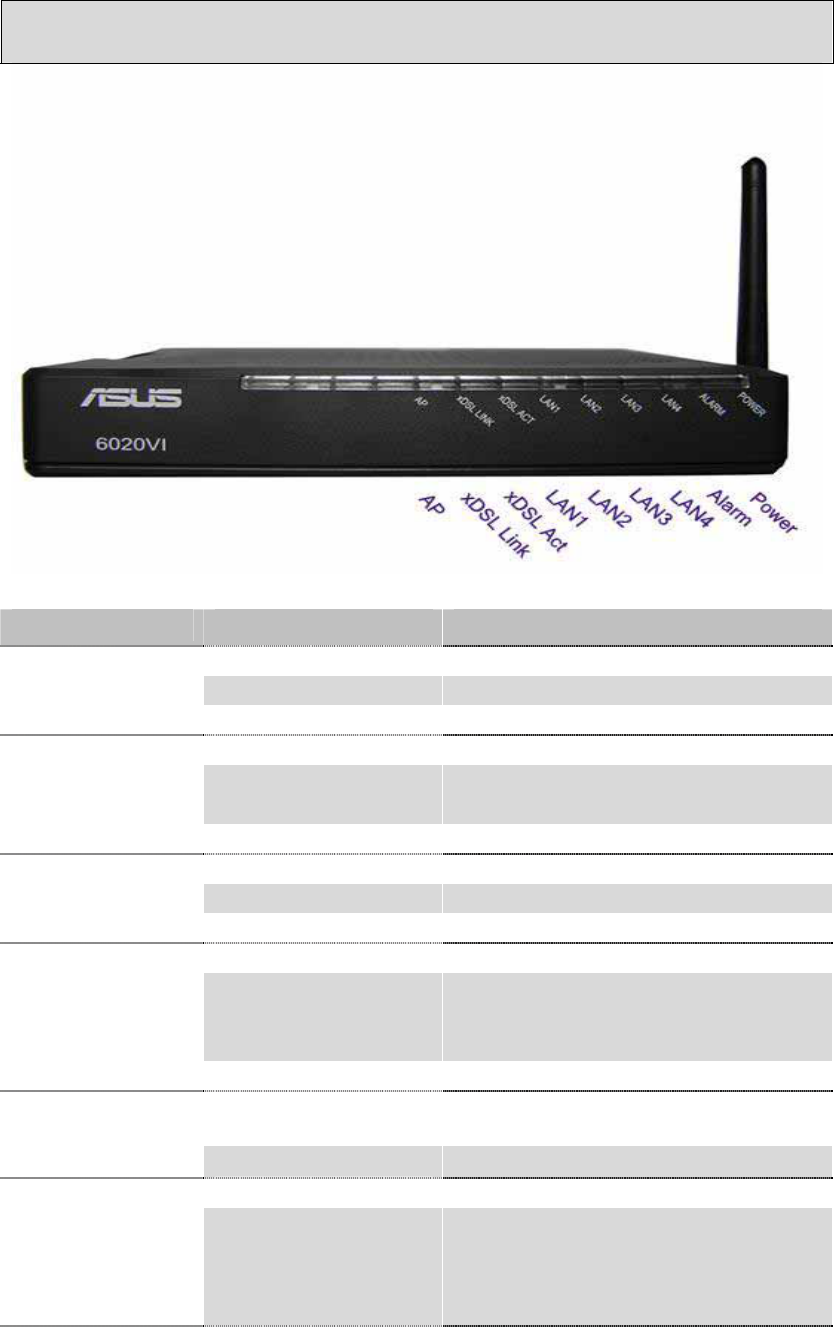
Front Panel View
LED Mode Indication
Solid Wireless is enabled.
No light Wireless is disabled.
AP Blinking Presence of wireless traffic.
Solid ADSL is connected.
No light ADSL is not connected.
ALARM LED will be red.
xDSL Link
Blinking Router is connected to ADSL.
Solid ADSL is connected; no traffic.
No light ADSL is not connected.
xDSL Act
Blinking Presence of ADSL traffic.
Solid Router is connected to LAN.
No light No connection to LAN. Check if
LAN cable is connected to
router.
LAN1-4
Blinking Presence of LAN traffic.
Solid (red) ADSL is not connected.
Alarm
No light ADSL is connected.
Solid Router is powered on.
Power No light
Router is not powered on.
Check if router is plugged in
and if the power switch is
turned on.
________________________________________________________________________
ASUS 4-Port Ethernet Switch +
5
Wi-Fi Router (AAM6X20VI-F1)
User Manual
Version 1.2
Document #: BD-AU0011-12
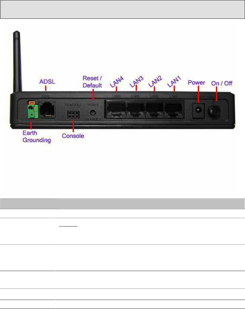
Back Panel View
Port Description
ADSL RJ-11 cable connects to the splitter provided.
Console Note: To be used for maintenance purposes by
service professionals only. If the router needs repair,
bring it to a service professional.
Reset /
Default
Restart—
press the button for less than 4 seconds.
Default Settings—
press the button for 4 seconds or
longer.
LAN1-4 RJ-45 cable connects the unit to an Ethernet device
such as a PC or a switch.
Power Connects to a 15VAC AC power adapter.
On / Off Press to turn the router on or off.
________________________________________________________________________
ASUS 4-Port Ethernet Switch +
6
Wi-Fi Router (AAM6X20VI-F1)
User Manual
Version 1.2
Document #: BD-AU0011-12
Installing the Router
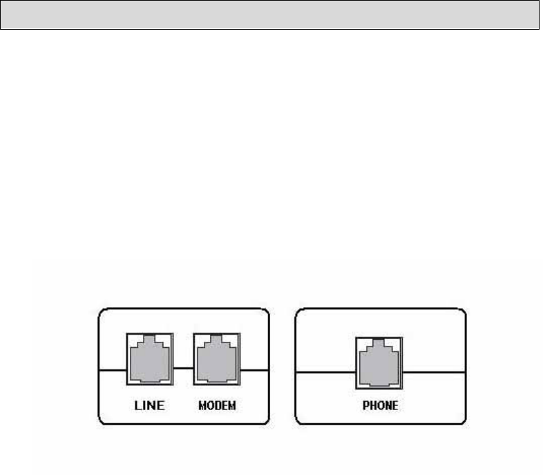
Connect the ADSL Line and Telephone
• Use an RJ-11 cable to connect the wall phone jack to the
line-end of the splitter (see below illustration of splitter).
• Attach another RJ-11 cable to the splitter, the modem-end,
and connect the other end to the router port labeled ADSL.
• The final RJ-11 cable will be connected between the
phone-end of the splitter and the telephone.
NOTE: See connections on the installation diagram.
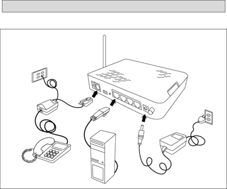
Connect the PC to the Router
• Connect one end of the RJ-45 cable to one of the 4 LAN
ports on the back of the router and the other end to the
Ethernet port of your computer.
• Attach any additional PCs to the router using RJ-45 cables
to the LAN ports on the back panel of the router.
Connect the Power Adapter
• Finish up by connecting the AC power adapter to the
POWER connector on the back of the router and plug the
adapter into a wall outlet or power strip.
• Turn on and boot up your PC and any LAN devices, such
as hubs or switches, and any computers connected to
them.
________________________________________________________________________
ASUS 4-Port Ethernet Switch +
7
Wi-Fi Router (AAM6X20VI-F1)
User Manual
Version 1.2
Document #: BD-AU0011-12
________________________________________________________________________
ASUS 4-Port Ethernet Switch +
8
Wi-Fi Router (AAM6X20VI-F1)
User Manual
Version 1.2
Document #: BD-AU0011-12
Installation Diagram
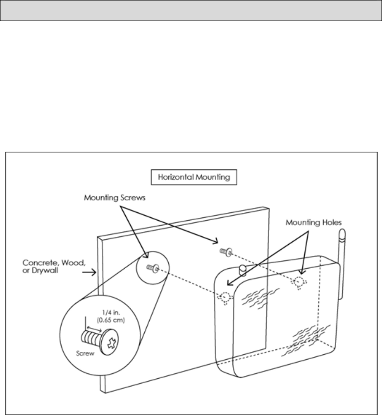
Mounting the Router
The router can be mounted on the wall with the screws provided.
Mounting can be done on wall material including concrete, wood,
or drywall. Select an appropriate location free from obstructions
or any possible interference. Make sure the cables can be easily
attached to the router without strain. The illustration below shows
how to mount the router horizontally on a wall.
________________________________________________________________________
ASUS 4-Port Ethernet Switch +
9
Wi-Fi Router (AAM6X20VI-F1)
User Manual
Version 1.2
Document #: BD-AU0011-12

________________________________________________________________________
ASUS 4-Port Ethernet Switch +
10
Wi-Fi Router (AAM6X20VI-F1)
User Manual
Version 1.2
Document #: BD-AU0011-12
Configuring Your Computer
Prior to accessing the router through the LAN port, note the
following necessary configurations—
• Your PC’s TCP/IP address: 192.168.1.__( the last number
is any number between 3 and 254)
• The router’s default IP address: 192.168.1.1
• Subnet mask: 255.255.255.0
Below are the procedures for configuring your computer. Follow
the instructions for the operating system that you are using.
Windows 2000
1. In the Windows taskbar, click on the Start button and point
to Settings, Control Panel, and Network and Dial-up
Connections (in that order).
2. Click on Local Area Connection. When you have the Local
Area Connection Status window open, click on Properties.
3. Listed in the window are the installed network components.
If the list includes Internet Protocol (TCP/IP), then the
protocol has already been enabled, and you can skip to
Step 10.
4. If Internet Protocol (TCP/IP) does not appear as an
installed component, then click on Install.
5. In the Select Network Component Type window, click on
protocol and then the Add button.
6. Select Internet Protocol (TCP/IP) from the list and then click
on OK.
7. If prompted to restart your computer with the new settings,
click OK.

________________________________________________________________________
ASUS 4-Port Ethernet Switch +
11
Wi-Fi Router (AAM6X20VI-F1)
User Manual
Version 1.2
Document #: BD-AU0011-12
8. After your computer restarts, click on the Network and Dial-
up Connections icon again, and right click on the Local
Area Connection icon and then select Properties.
9. In the Local Area Connection Properties dialog box, select
Internet Protocol (TCP/IP) and then click on Properties.
10. In the Internet Protocol (TCP/IP) Properties dialog box,
click in the radio button labeled Use the following IP
address and type 192.168.1.x (where x is any number
between 2 and 254) and 255.255.255.0 in the IP address
field and Subnet Mask field.
11. Click on OK twice to save your changes and then close
the Control Panel.
Windows XP
1. In the Windows taskbar, click on the Start button and point
to Settings and then click Network Connections.
2. In the Network Connections window, right click on the Local
Area Connection icon and click on properties.
3. Listed in the Local Area Connection window are the
installed network components. Make sure the box for
Internet Protocol (TCP/IP) is checked and then click on
Properties.
4. In the Internet Protocol (TCP/IP) Properties dialog box, click
in the radio button labeled Use the following IP address and
type 192.168.1.x (where x is any number between 2 and
254) and 255.255.255.0 in the IP address field and Subnet
Mask field.
5. Click on OK twice to save your changes and then close the
Control Panel.
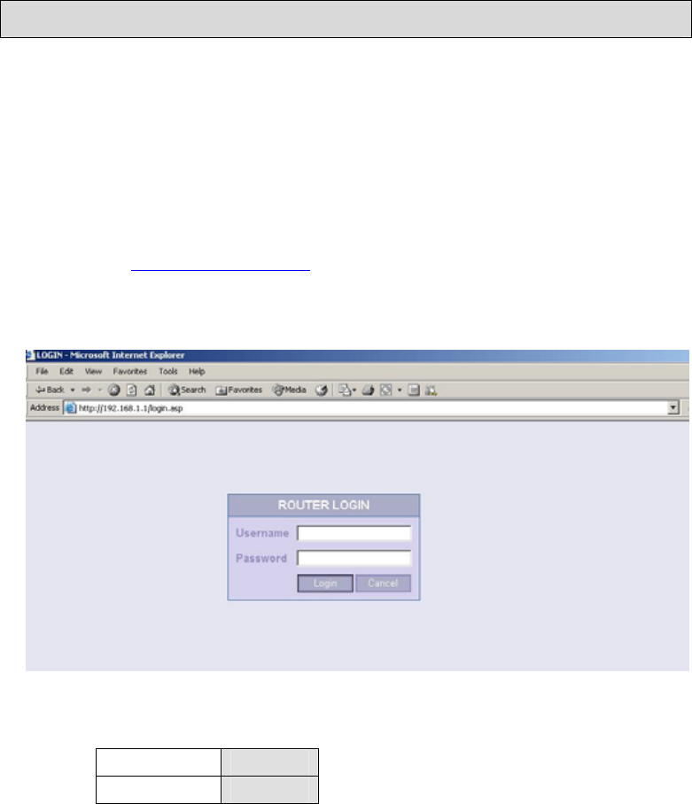
Log in to the Router
After installing the hardware portion of your router, you will
need to configure the router through the user interface. Below
are the steps for logging into the router.
Steps:
1. Launch your web browser.
2. Type
http://192.168.1.1 in the URL address bar and press
Enter.
3. The below login screen will be displayed.
4. Enter the below username / password and click on LOGIN.
Username root
Password admin
5. After logging in, you will be able to configure the router.
________________________________________________________________________
ASUS 4-Port Ethernet Switch +
12
Wi-Fi Router (AAM6X20VI-F1)
User Manual
Version 1.2
Document #: BD-AU0011-12
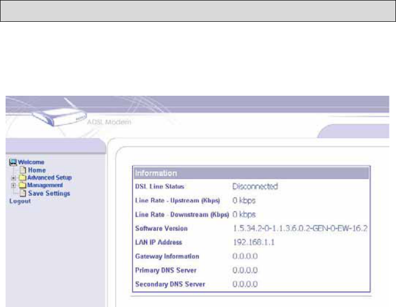
Home Screen
After logging in, the home screen shows information on the router,
including the connection status, the upstream / downstream line
rate, software version, IP address, etc.
________________________________________________________________________
ASUS 4-Port Ethernet Switch +
13
Wi-Fi Router (AAM6X20VI-F1)
User Manual
Version 1.2
Document #: BD-AU0011-12
Advanced Setup
This section of the user manual is on the advanced configurations
of the router. The topics under Advanced Setup are
ADSL, WAN,
LAN, VLAN, Firewall, NAT,
and
Route.
ADSL
The following section will explain the ADSL portion of the
configurations, including a status screen as shown below.
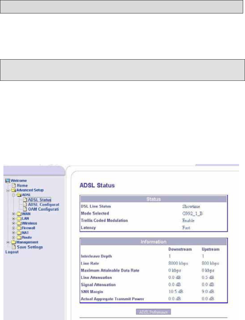
ADSL Status
This section of the router displays statuses and information on
your ADSL connection. You can also perform an ADSL
performance test.
________________________________________________________________________
ASUS 4-Port Ethernet Switch +
14
Wi-Fi Router (AAM6X20VI-F1)
User Manual
Version 1.2
Document #: BD-AU0011-12
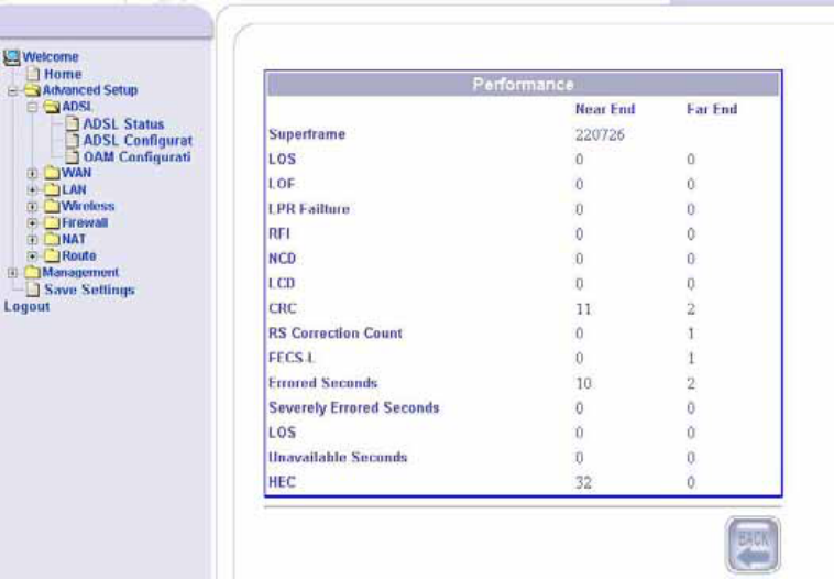
Clicking the ADSL Performance button at the bottom of the ADSL
Status page displays the following screen.
ADSL Configuration
In the ADSL Configuration screen, select the encapsulation mode
that you will be using, which include auto select, ADSL, ADSL2,
and ADSL2+, G.992.3 Annex I/J/M, G.992.5 Annex I/J/M, Annex
B auto select, and Annex M auto select. The table shows tone
numbers 0-511. There are also two buttons—showtime lock and
quiet mode—which you can select. Click Apply after making your
selection to save and reboot the router.
________________________________________________________________________
ASUS 4-Port Ethernet Switch +
15
Wi-Fi Router (AAM6X20VI-F1)
User Manual
Version 1.2
Document #: BD-AU0011-12
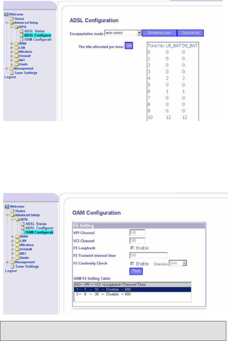
OAM Configuration
The OAM (Operation Administration Maintenance) Test performs
fault detection and notification for each connection with the option
to enable standard loopback (end-to-end or segment).
WAN
To configure the WAN settings, access the ADSL configuration
screens by clicking on the WAN folder on the left menu bar under
Advanced Setup.
________________________________________________________________________
ASUS 4-Port Ethernet Switch +
16
Wi-Fi Router (AAM6X20VI-F1)
User Manual
Version 1.2
Document #: BD-AU0011-12
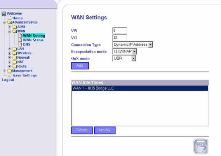
WAN Settings
Below is the first page of the WAN Settings section which allows
you to enter the VPI / VCI, connection type, encapsulation mode,
and QoS mode for your WAN interface. After you make your
selections, click on
Add
to make specific settings for the
connection that you choose.
The connection types include the following—
• Dynamic IP Address
• Static IP Address
• PPPoE
• PPPoA
• Bridge
Below is the screen you will see if you select Dynamic IP Address
and click on Apply. There are no fields to enter except to select
the protocol that you are using.
________________________________________________________________________
ASUS 4-Port Ethernet Switch +
17
Wi-Fi Router (AAM6X20VI-F1)
User Manual
Version 1.2
Document #: BD-AU0011-12
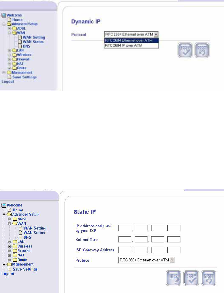
If you are using a Static IP, then the below screen includes fields
that need to be filled out with information from your ISP. You will
need to find out the following information—
• IP Address assigned by your ISP
• Subnet Mask
• ISP Gateway Address
• Protocol (either RFC 2684 Ethernet over ATM or RFC 2684
IP over ATM)
If you are using PPPoE or PPPoA, then obtain the following
information from your ISP—
• Username / Password
• MTU—Maximum Transmission Unit, it is the largest physical
packet size, measured in bytes that a network can transmit
before it must be divided into a smaller sized-packet.
• Dial On Demand (enable or disable)—this feature allows for
automatic reconnecting to your ISP if your connection is
lost.
________________________________________________________________________
ASUS 4-Port Ethernet Switch +
18
Wi-Fi Router (AAM6X20VI-F1)
User Manual
Version 1.2
Document #: BD-AU0011-12
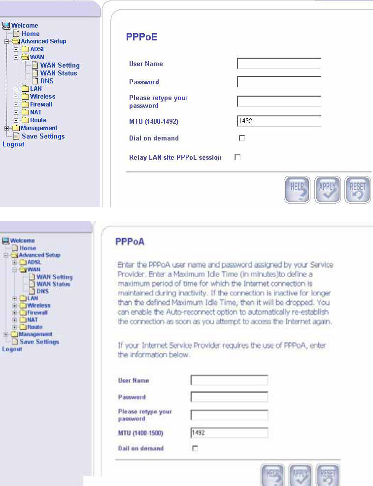
• Relay LAN site PPPoE session—this feature is where you
can relay pppoe packets coming from the pc to the server
instead of the router sending the pppoe packets from the
router itself.
Selecting Bridge Mode automatically changes your connection
type to bridge, which changes the WAN status as shown in the
screen below (same as the WAN status page).
WAN Status
________________________________________________________________________
ASUS 4-Port Ethernet Switch +
19
Wi-Fi Router (AAM6X20VI-F1)
User Manual
Version 1.2
Document #: BD-AU0011-12
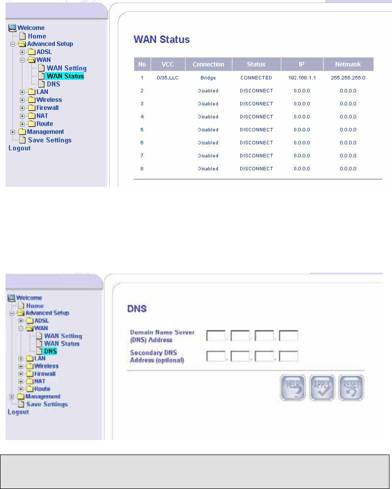
The WAN status page is an informational page that shows which
connection type has been selected for the WAN(s).
DNS
Enter the IP address of the Domain Name Server and the
secondary DNS Address (if available) and click Apply.
LAN
To configure the LAN settings of the router, click on the LAN
folder on the left menu bar.
LAN Settings
Enter the LAN interface IP address and the LAN subnet mask of
the router. Then select the DHCP mode from the list of choices—
________________________________________________________________________
ASUS 4-Port Ethernet Switch +
20
Wi-Fi Router (AAM6X20VI-F1)
User Manual
Version 1.2
Document #: BD-AU0011-12
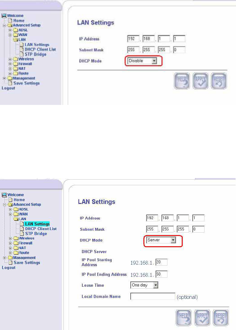
• Disable
• Server
• Relay Agent
Click on Apply after you have finished completing the fields.
Below is a screen showing a disabled DHCP mode. Notice that
there are no additional required settings after you disable DHCP
mode.
If you select a Server DHCP mode, then enter the range of IP
addresses that can be assigned in the IP Pool Starting Address
and IP Pool Ending Address. Also enter the lease time (from a
half hour to a maximum of two weeks) for the use of these IP
addresses before they must be renewed. Click on Apply to save
these settings.
________________________________________________________________________
ASUS 4-Port Ethernet Switch +
21
Wi-Fi Router (AAM6X20VI-F1)
User Manual
Version 1.2
Document #: BD-AU0011-12
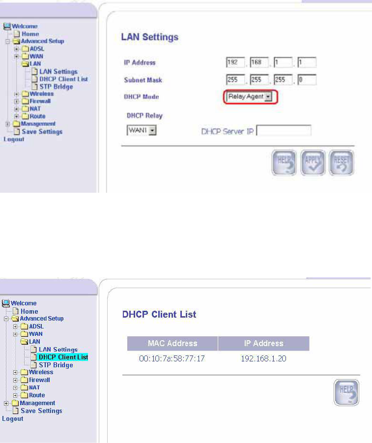
If you set your router as the relay agent, then enter the DHCP
Server’s IP address that the router will be routing requests from
the PC(s) to the DHCP server. Also select the WAN channel that
you are connected to. Each channel can be unique PVC and can
be assigned one protocol. Find out from your ISP what protocol
and PVC to use.
DHCP Client List
This screen shows the list of IP addresses that have been
obtained through a DHCP server.
________________________________________________________________________
ASUS 4-Port Ethernet Switch +
22
Wi-Fi Router (AAM6X20VI-F1)
User Manual
Version 1.2
Document #: BD-AU0011-12
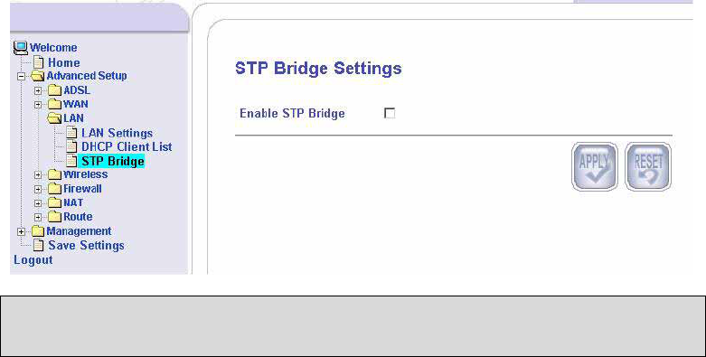
STP Bridge
If you decide to enable the STP Bridge function of the router, then
click on the box and then Apply to save.
Wireless
This section allows you to configure wireless settings on your
router.
Wireless Settings
This section is the wireless settings page with all the fields
already filled in with the router’s default information. You will not
need to change the information unless you have specific changes.
Below is a description of the wireless settings—
AP Name—this is the name for your router
SSID Mode—includes
Advertise SSID
and
Hide SSID
ESSID—this is the same as the AP name
Channel ID—includes channel 1 to 14
Preamble Mode—includes short and long preamble and auto
Operation Mode—includes 802.11b rate only, 802.11g rate only,
and auto
Beacon Interval
—
a packet of information that is sent from a
connected device to all other devices where it announces its
availability and readiness. A beacon interval is a period of time
(sent with the beacon) before sending the beacon again. The
beacon interval may be adjusted in milliseconds (ms).
RTS Threshold (Request to Send Threshold)—determines the
packet size of a transmission through the use of the router to help
control traffic flow.
Fragmentation Threshold
--
used to fragment packets that help
________________________________________________________________________
ASUS 4-Port Ethernet Switch +
23
Wi-Fi Router (AAM6X20VI-F1)
User Manual
Version 1.2
Document #: BD-AU0011-12
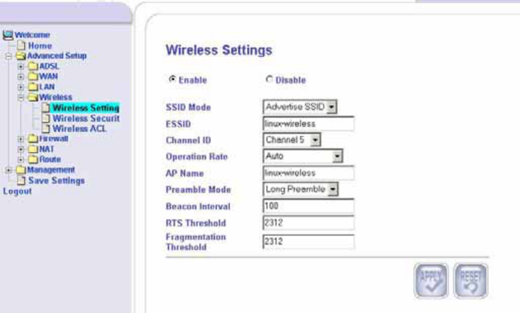
improve performance in the presence of radio frequency (RF)
interference.
If you wish to disable wireless, then click on the Disable radio
button and click on
Apply
.
Wireless Security
Security settings can be changed on this page. Below are the
fields that can be configured.
• Authentication Type—
• Open—anyone can access the network. The
default is a disabled WEP encryption setting.
• Shared—WEP encryption is enabled and
encryption key strength of 64-bit or 128-bit needs
to be selected. Click on Set Encryption Keys to
manually set the network encryption keys. Up to 4
different keys can be set and you can come back
to select which one to use at anytime.
• WPA-TLS (Wi-Fi Protected Access – Transport
Layer Protocol)
• WPA-PSK (Wi-Fi Protected Access – Pre-Shared
Key)—WPA for home and SOHO environments
also using the same strong TKIP encryption, per-
packet key construction, and key management
that WPA provides in the enterprise environment.
________________________________________________________________________
ASUS 4-Port Ethernet Switch +
24
Wi-Fi Router (AAM6X20VI-F1)
User Manual
Version 1.2
Document #: BD-AU0011-12
________________________________________________________________________
ASUS 4-Port Ethernet Switch +
25
Wi-Fi Router (AAM6X20VI-F1)
User Manual
Version 1.2
Document #: BD-AU0011-12
The main difference is that the password is
entered manually. A group re-key interval time is
also required.
• Encryption Type— to encrypt data, select the encryption
type that you wish to use. The range is from no
encryption at all to the stronger encryption type,
TKIP.
• No Encryption
• WEP 64 (10 digits)
• WEP 128 (26 digits)
• Standard 802.1X (WEP)
• TKIP
• Active Key—select which key you wish to be active.
• None
• Key 1 to Key 4
If you have a radius server, then continue onto the next section.
Fill in the following information regarding your radius server—
• NAS Identifier
• Radius server address
• Radius Server Port
• Radius Server Secret
• 1x Key Length
The next section is only required if you select authentication type
WPA-PSK. Enter the PSK Key and click to enable passphrase.
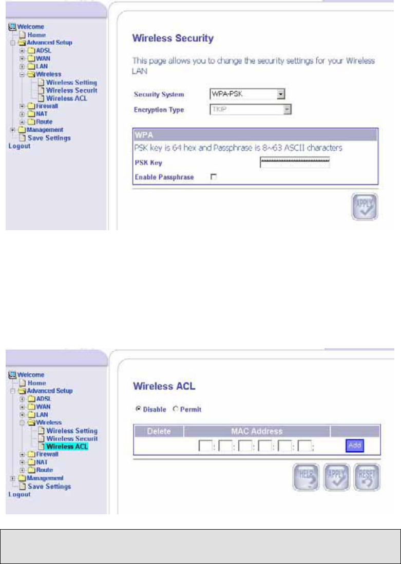
Wireless ACL
The Wireless ACL (Access Control List) page allows you to enter
the MAC addresses that you will permit access to your wireless
router. If you wish to disable this feature, then click on the disable
radio button and click on
Apply
.
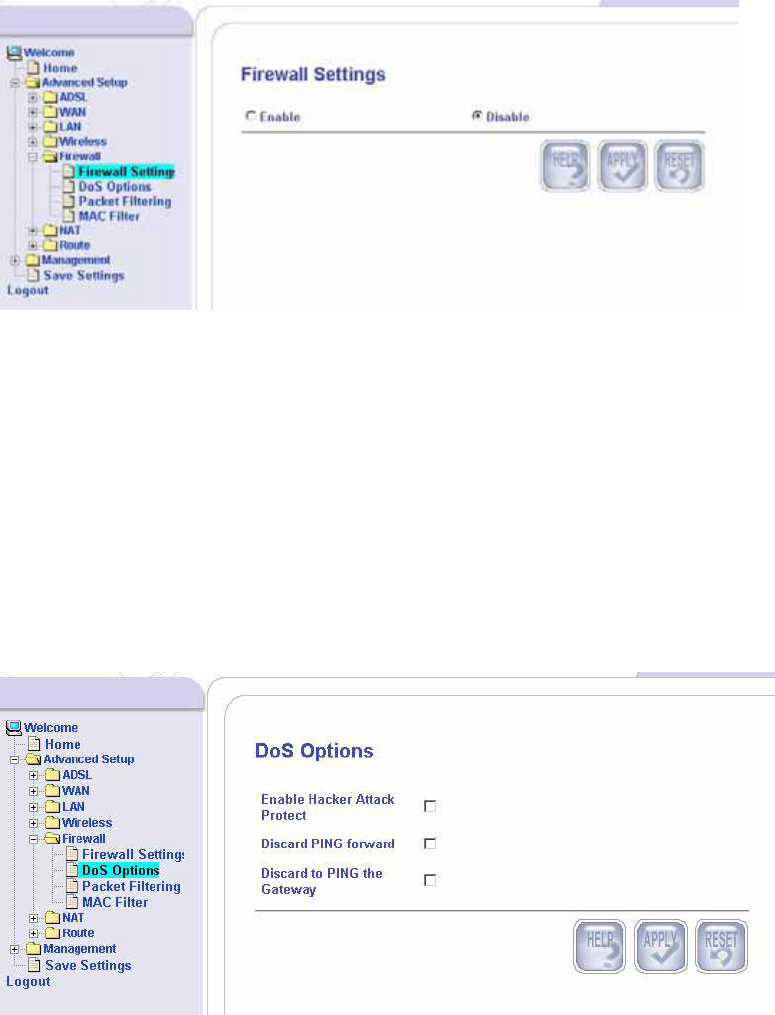
Firewall
Firewall Settings
To enable / disable your router’s built-in firewall, select your
choice here and click on Apply to save the settings.
________________________________________________________________________
ASUS 4-Port Ethernet Switch +
26
Wi-Fi Router (AAM6X20VI-F1)
User Manual
Version 1.2
Document #: BD-AU0011-12
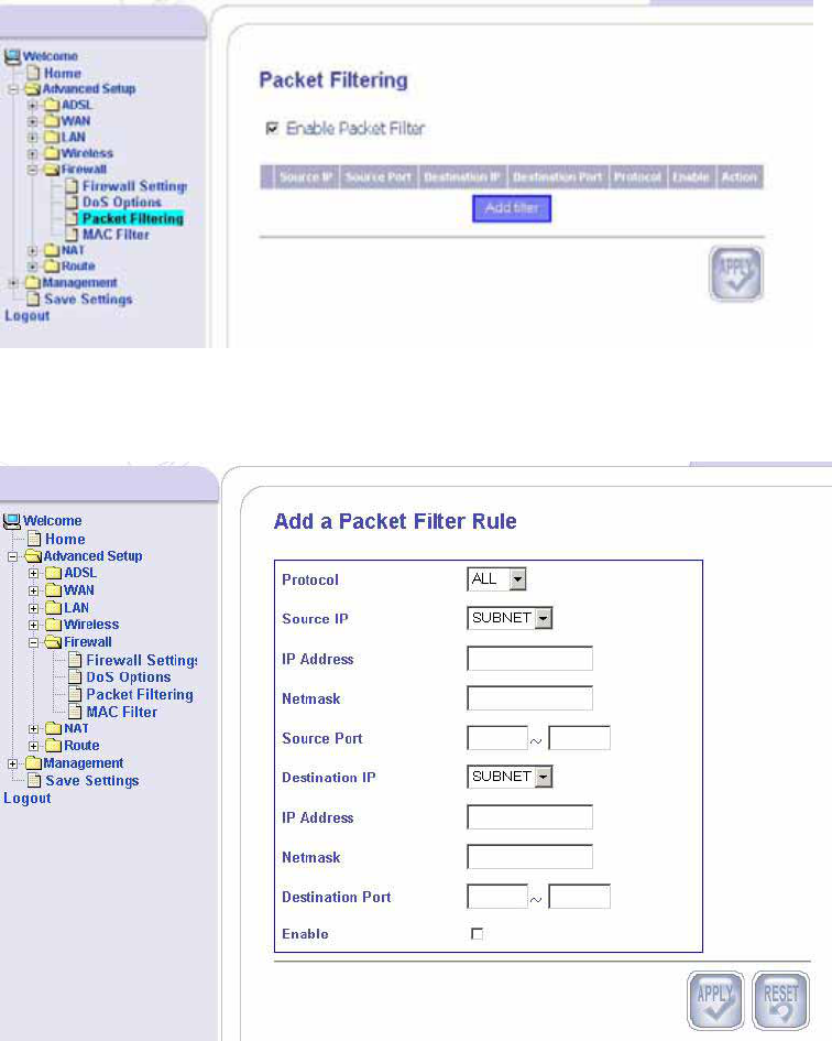
DoS Options
This page lets you configure DoS (Denial of Service) firewall
options. Options include the following—
• Enable Hacker Attack Protect—if this box is checked, then
all hacker attack events are logged and dropped.
• Discard PING Forward—if this box is checked, then all PING
from the WAN side are dropped.
• Discard PING the Gateway—if this box is checked, then all
PING from the router LAN side is dropped.
________________________________________________________________________
ASUS 4-Port Ethernet Switch +
27
Wi-Fi Router (AAM6X20VI-F1)
User Manual
Version 1.2
Document #: BD-AU0011-12
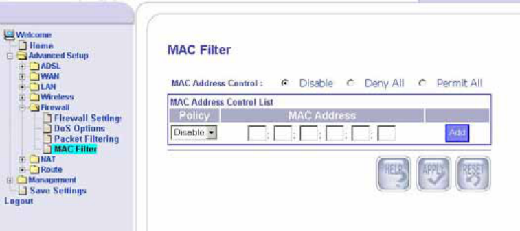
Packet Filtering
This page allows you to permit or deny network traffic based on
the data source, destination, service or protocol of the data
packets. To set a filter, make sure that
Enable Packet Filter
is
checked and then click on
Add
to proceed.
Then you will continue to the below screen which allows you to
enter the rule by which you wish to filter incoming data packets.
Select from the following protocols—
• TCP (Transmission Control Protocol)
• UDP (User Datagram Protocol)
________________________________________________________________________
ASUS 4-Port Ethernet Switch +
28
Wi-Fi Router (AAM6X20VI-F1)
User Manual
Version 1.2
Document #: BD-AU0011-12
• ICMP (Internet Control Message Protocol)
• AH (Authentication Header)
• ESP (Encapsulation Security Protocol)
• ALL—all protocols
When a source host sends secure datagrams to a destination
host, it does so with either the AH protocol or with the ESP
protocol. The AH protocol provides source authentication and
data integrity but does not provide secrecy. The ESP protocol
provides data integrity and secrecy.
• Source IP / Destination IP—select from all, single, or subnet
• IP Address-- this is the IP address of the host from where
the packet is coming from and where the packet is going.
• Netmask—this is the subnet mask of the source and
destination of the packet.
• Source Port / Destination Port—enter the port numbers of
the packet’s source and destination.
• Enable—click if you want to enable packet filtering.
MAC Filter
To control traffic by using MAC addresses, configurations can be
set as follows—
For MAC Address Control, select disable if you do not want to
filter by MAC addresses at all. Selecting Deny All means that you
will not allow any MAC addresses to enter and Permit All means
that you will let all MAC addresses to enter. The MAC Address
Control List allows you to control certain MAC addresses by
permitting or denying their access.
________________________________________________________________________
ASUS 4-Port Ethernet Switch +
29
Wi-Fi Router (AAM6X20VI-F1)
User Manual
Version 1.2
Document #: BD-AU0011-12
________________________________________________________________________
ASUS 4-Port Ethernet Switch +
30
Wi-Fi Router (AAM6X20VI-F1)
User Manual
Version 1.2
Document #: BD-AU0011-12
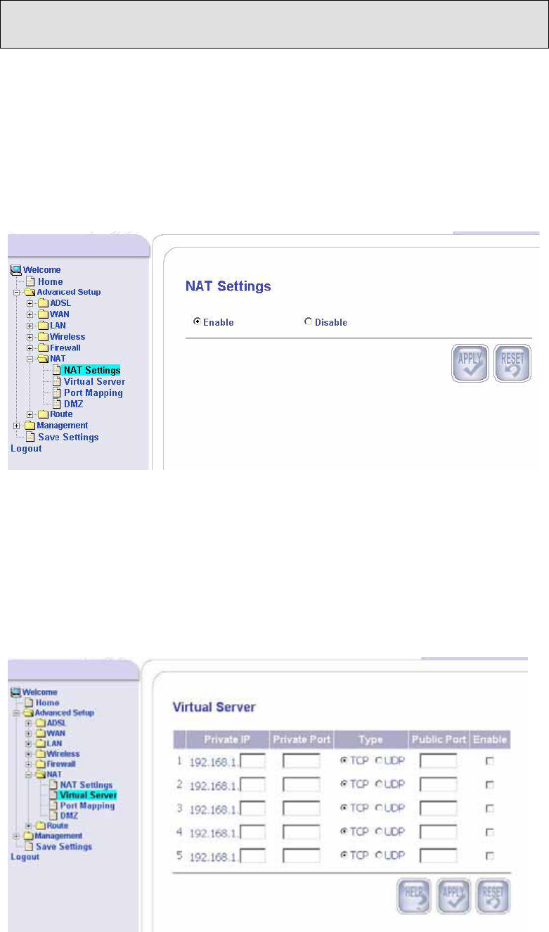
NAT
NAT Settings
NAT (Network Address Translation) is a technique in which the
source and/or destination address of IP packets are rewritten as
they pass through a router or firewall. Generally, it is used to
allow several hosts on a private network to access the Internet
using a single public IP address. This screen allows you to
enable or disable NAT.
Virtual Server
Your router has the option to be configured as a virtual server.
The private IP and private port is the LAN IP and port number that
the public port is redirected to. The WAN side will only see the
public port. Depending on the requested service (TCP / UDP port
number), the router will redirect the external service request to the
appropriate server.
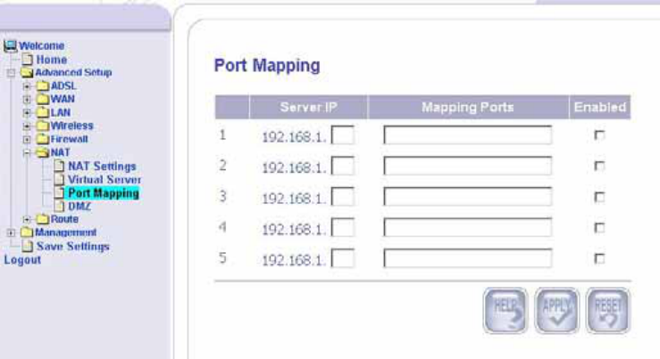
Port Mapping
Port Mapping allows WAN clients to access services on the LAN
by controlling the incoming port ranges assigned to the server IP.
The LAN side acts as the server and the WAN side acts as the
client. Enter the IP address of the LAN and a set or a range of
port numbers that you will allow to access the specific server.
The Port Mapping screen has several fields that need to be filled
out before the setup is complete. Below is the required
information—
• Server IP—the IP address of the local machine.
• Mapping Ports—a range of ports or a specified port where
packets are to be routed.
• Enabled—to enable a specified entry of the port mapping.
DMZ
DMZ (demilitarized zone) allows contained hosts to provide
services to the external network, while protecting the internal
network from possible intrusions into those hosts.
________________________________________________________________________
ASUS 4-Port Ethernet Switch +
31
Wi-Fi Router (AAM6X20VI-F1)
User Manual
Version 1.2
Document #: BD-AU0011-12
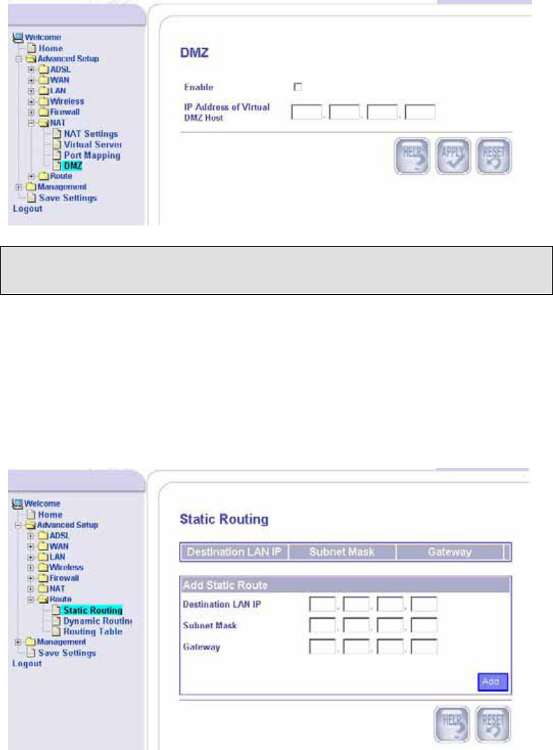
Click to enable and then enter the IP address of the DMZ host.
Route
Static Routing
To add a static route, you will need to enter the following
information—
• Destination LAN IP
• Subnet Mask
• Gateway
Dynamic Routing
Dynamic routing can be enabled or disabled here. If you enable,
then select the listen mode to be used. Selections include the
following—
• RIP1
________________________________________________________________________
ASUS 4-Port Ethernet Switch +
32
Wi-Fi Router (AAM6X20VI-F1)
User Manual
Version 1.2
Document #: BD-AU0011-12
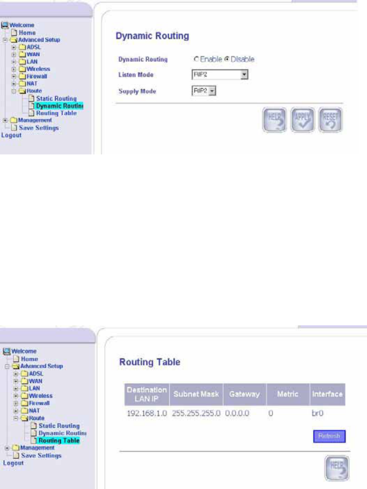
• RIP2
• Both (RIP1 + RIP2)
Also needed is the supply mode, which include RIP1 and RIP2.
When finished, click on Apply to save the selections.
Routing Table
The routing table is an informational page that allows you to see
how many routings are on your routing table. The table displays
the following information—
• Destination LAN IP
• Subnet mask
• Gateway
• Metric—this counts the number of hops.
• Interface
________________________________________________________________________
ASUS 4-Port Ethernet Switch +
33
Wi-Fi Router (AAM6X20VI-F1)
User Manual
Version 1.2
Document #: BD-AU0011-12
Management
This section of the router allows you to set up any controls you
may want to have on your network as well as to maintain the
system with firmware upgrades, etc. Also in this section is the
system log that allows you to view system information.
System
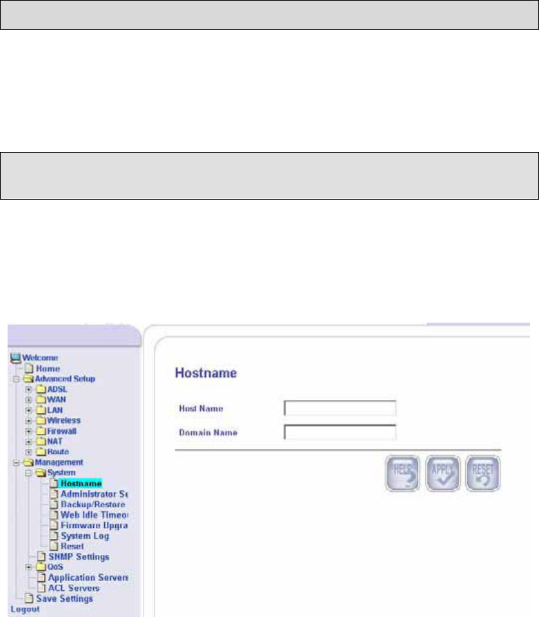
Hostname
Enter the hostname representing your host and the domain name
so you won’t have to enter the IP address anymore and only need
to type the hostname.
________________________________________________________________________
ASUS 4-Port Ethernet Switch +
34
Wi-Fi Router (AAM6X20VI-F1)
User Manual
Version 1.2
Document #: BD-AU0011-12
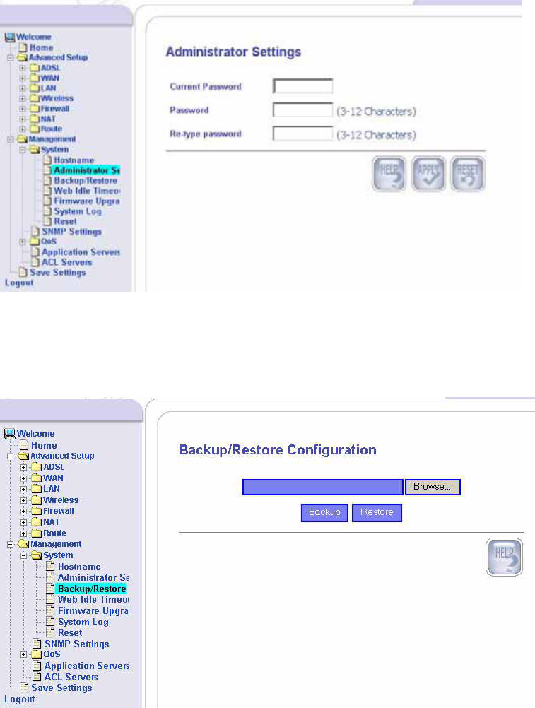
Administrator Settings
To set a password so you can restrict management access to
your router, enter the current password and the new password
that you wish to change to and reconfirm it again.
Backup / Restore
This page allows you to save a backup copy of your
configurations or to restore previously saved configurations.
________________________________________________________________________
ASUS 4-Port Ethernet Switch +
35
Wi-Fi Router (AAM6X20VI-F1)
User Manual
Version 1.2
Document #: BD-AU0011-12
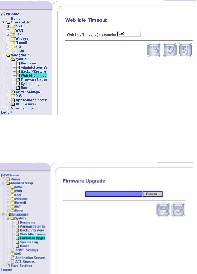
Web Idle Timeout
This page allows you to set the number of minutes (in seconds)
that the router will log due to inactivity.
Firmware Upgrade
To upgrade the router with the newest firmware, click Browse to
find the file on your pc (after downloading it from the firmware
site). Then click on Apply to continue with the upgrade.
________________________________________________________________________
ASUS 4-Port Ethernet Switch +
36
Wi-Fi Router (AAM6X20VI-F1)
User Manual
Version 1.2
Document #: BD-AU0011-12
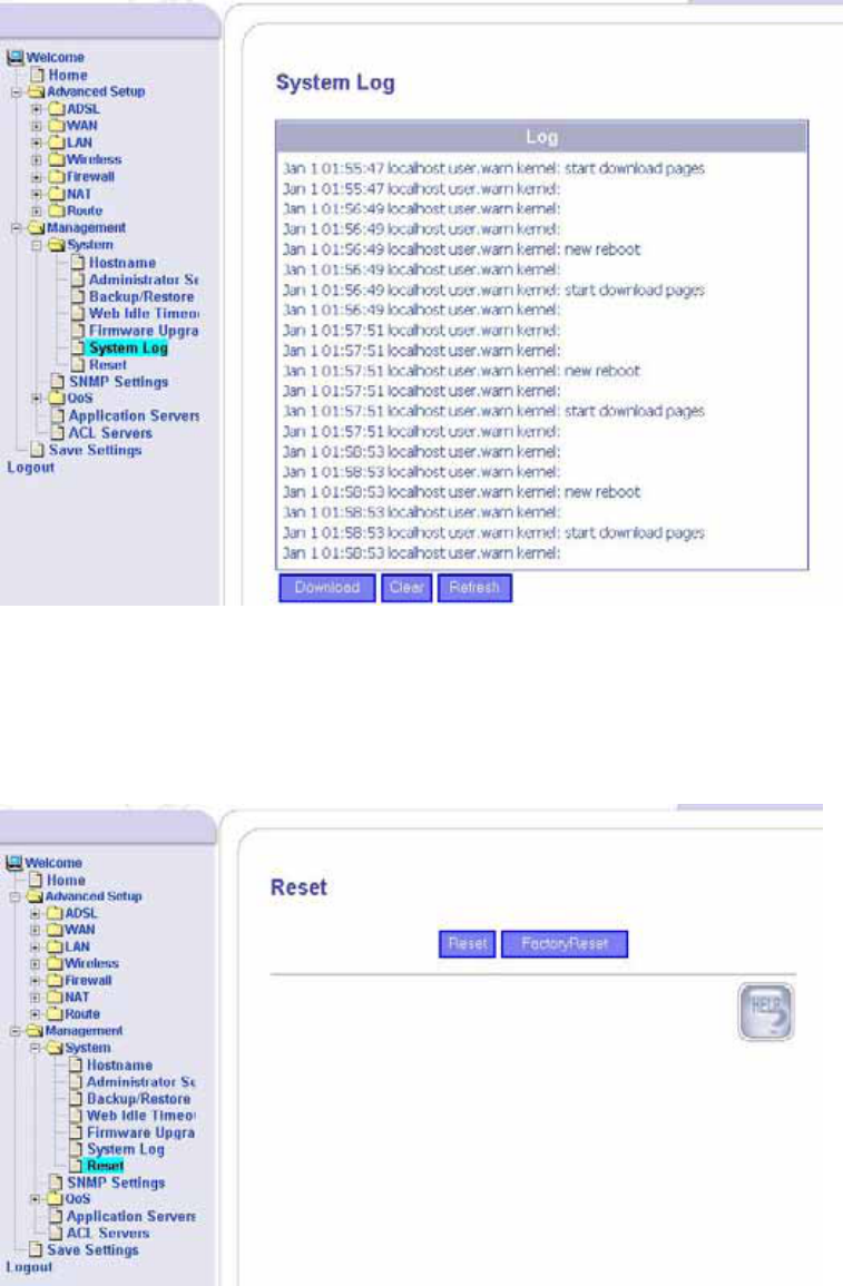
System Log
This screen shows a log of the system’s activity.
Reset
To reset the router without changing all the configured settings,
click on Reset. To reset the router back to its factory settings,
click on Factory Reset.
________________________________________________________________________
ASUS 4-Port Ethernet Switch +
37
Wi-Fi Router (AAM6X20VI-F1)
User Manual
Version 1.2
Document #: BD-AU0011-12
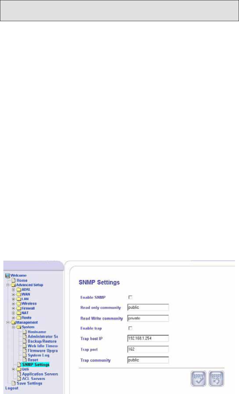
SNMP Settings
SNMP (Simple Network Management Protocol) settings can be
accessed here. Settings here include the following—
• Enable SNMP—to enable this feature, click the box.
• Read Only Community--The SNMP Read-Only Community
String is like a password. It is sent along with each SNMP
Get-Request and allows (or denies) access to device. The
router is shipped with a default password of "public". It’s a
good idea to change the community string to keep intruders
from getting information about the network setup. Even if
it's only read-access, SNMP can divulge a lot of information
about the network that could be used to compromise it.
• Read Write Community—this is set to private (this should
never be set to public).
• Enable Trap—to enable the trap, click the box. A SNMP
Trap is an unsolicited message from a device to an SNMP
console that the device is in an interesting state. Traps
might indicate power-up or link-up/down conditions
temperatures exceeding certain thresholds, high traffic, etc.
Traps provide an immediate notification for an event that
might only be discovered during occasional polling.
• Trap Host IP—the IP address of the trap host.
• Trap Port—the port number of the trap host.
• Trap Community—public or private.
________________________________________________________________________
ASUS 4-Port Ethernet Switch +
38
Wi-Fi Router (AAM6X20VI-F1)
User Manual
Version 1.2
Document #: BD-AU0011-12
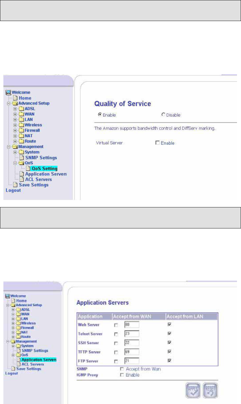
QoS (Under Development)
QoS Settings
This screen allows you to enable or disable quality of service for
your router. You can also enable or disable the bandwidth control
and DiffServ marking.
Application Servers
To configure application server settings, for each of the listed
applications, select whether or not to accept from the WAN and/or
LAN and enter the port number assigned. Also, if you want to
enable the IGMP (Internet Group Management Protocol) Proxy,
click on the Enable box.
________________________________________________________________________
ASUS 4-Port Ethernet Switch +
39
Wi-Fi Router (AAM6X20VI-F1)
User Manual
Version 1.2
Document #: BD-AU0011-12
________________________________________________________________________
ASUS 4-Port Ethernet Switch +
40
Wi-Fi Router (AAM6X20VI-F1)
User Manual
Version 1.2
Document #: BD-AU0011-12
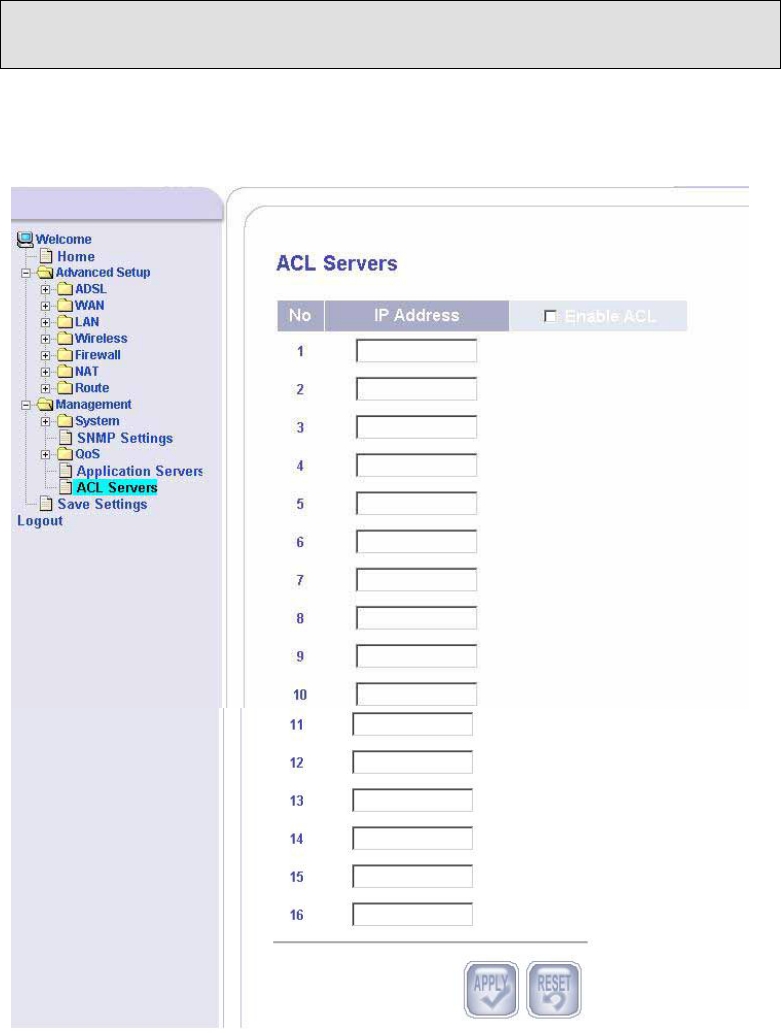
ACL Servers
The ACL (Access Control List) Server page allows you to enter
the IP addresses that you will allow to access your router.

Appendix
FCC Warning Statement
This device complies with Part 15 of the FCC Rules. Operation is
subject to the following two conditions:
(1) this device may not cause harmful interference, and
(2) this device must accept any interference received, including
interference that may cause undesired operation.
This equipment has been tested and found to comply with thelimits for a class
B digital device, pursuant to part 15 of the FCC Rules. These limits are
designed to provide reasonable protection against harmful interference in a
residential installation. This equipment generates, uses and can radiate radio
frequency energy and, if not installed and used in accordance with the
instructions, may cause harmful interference to radio communications.
However, there is no guarantee that interference will not occur in a particular
installation. If this equipment does cause harmful interference to radio or
television reception, which can be determined by turning the equipment off and
on, the user is encouraged to try to correct the interference by one or more of
the following measures:
--- Reorient or relocate the receiving antenna.
--- Increase the separation between the equipment and receiver.
--- Connect the equipment into an outlet on a circuit different from that to which
the receiver is connected.
--- Consult the dealer or an experienced radio/TV technician for help.
Any changes or modifications not expressly approved by the party responsible
for compliance could void the user’s authority to operate the equipment.
This device and its antenna(s) must not be co-located or operating in
onjunction with any other antenna or transmitter
To maintain compliance with FCC’s RF exposure guidelines, this equipment
should be installed and operated with minimum distance 20cm between the
radiator and your body. Use on the supplied antenna.

Declaration of Conformity for R&TTE directive 1999/5/EC
Essential requirements – Article 3
Protection requirements for health and safety – Article 3.1a
Testing for electric safety according to EN 60950 has been conducted.
These are considered relevant and sufficient. Protection requirements for
electromagnetic compatibility – Article 3.1b
Testing for electromagnetic compatibility according to EN 301
489-1 and EN 301 489-17 has been conducted. These are
considered relevant and sufficient.
Effective use of the radio spectrum – Article 3.2
Testing for radio test suites according to EN 300 328 has been
conducted. These are considered relevant and sufficient.
CE Mark Warning
This is a Class B product, in a domestic environment, this product
may cause radio interference, in which case the user may be
required to take adequate measures.