ASUSTeK Computer AAM6KVIT4 ADSL WIRELESS MODEM ROUTER User Manual manual
ASUSTeK Computer Inc ADSL WIRELESS MODEM ROUTER manual
USERS MANUAL

AAM6020VI ADSL Wireless Modem Router Quick Installation Guide
Page 1
Quick Installation Guide
ASUS® AAM6020VI
ADSL Wireless Modem Router
¾Do not open the housing!
¾Use only the power supply provided with this device.
¾Use only the cables provided with this device and do
not perform any modification on them.
Rev 1.0
Nov, 23, 2004
P/N: 15-0680980F0

AAM6020VI ADSL Wireless Modem Router Quick Installation Guide
Page 2
Before you begin
Before installing your ADSL wireless modem router, please carefully check the following
requirements with your computer. This ADSL wireless modem router is equipped with four
10/100Mbps RJ-45 Ethernet switch ports and 802.11g wireless Access Point. You can connect to the
modem by Ethernet or wireless interface.
Unpacking and Inspection
Verify following items came with your ADSL Modem:
AAM6020VI unit
RJ-11 ADSL phone cable
RJ-45 UTP cable
Quick Installation Guide
Power adapter and splitter
Note: If any items are missing or damaged, please contact your local Sales Office for service.
System Requirements
IBM compatible, Macintosh or other OS-independent workstation supports TCP/IP.
An Ethernet port supports 10Mbps or 10/100Mbps TCP/IP connection on your PC.
For system configuration using the supplied web-based program: a web browser such
as Internet Explorer v5.5 or later
A wireless interface has installed properly on your PC, and it must support IEEE
802.11b or 802.11g wireless standard interface.
You can connect any one of modem four switch ports on the rear panel to PC NIC
Ethernet port. If you want to allow multiple computers (more than four PCs) to enjoy
internet through ADSL Modem, please purchase a hub/switch to link directly to
Ethernet port. You can contact your internet service provider to get more information
on this.
Caution:
1. If you want to use private Ethernet UTP cable linking between wireless modem
router with PC, please make sure that cable quality must conform to Cat.5
upward and cable’s length can’t exceed over 100 meters.
2. Please make sure that wireless modem router’s wireless signal could be accessed
by wireless interface on PC, and without any interference by electromagnetic
wave device or obstacle around the corner.

AAM6020VI ADSL Wireless Modem Router Quick Installation Guide
Page 3
Getting Started
Hardware Installation
Please follow the steps in the sequence outlined below. Fail to do so could result in damage of
your ADSL wireless modem.
Step 1: Connect a RJ-11 cable from wall phone jack to the connector “LINE” on the back of
the modem.
Step 2: Connect the AC adapter to the modem by inserting the barrel-shaped connector into the
mating power connector on the back of the modem, and plug in the adapter to a wall outlet
or a power strip.
Step 3: Connect any LAN port on the back of the modem with a UTP cable, and other end of
UTP cable directly link to RJ-45 port of your PC’s network card.
Step 4: Power on your PC and modem, now you are ready to configure PC.
Note: You can also use wireless interface to configure your modem, then please
directly proceed step 4 and make sure your wireless card driver has been installed
properly.
Caution: Please do not power on your PC and modem before connecting
steps are finished as mentioned above.
AAM6020VI ADSL Wireless Modem Router Quick Installation Guide
Page 4
1. Configuring Your Computers
1.1 Using Wired or Wireless Network Interface Card
Before you start to access AAM6020VI via Ethernet or Wireless, please configure your PC’s
TCP/IP address to be 192.168.1.x, where x could be any number between 2 to 254, subnet mask is
255.255.255.0, and Default gateway is 192.168.1.1 which is default IP address of ADSL modem.
Note:
By default, the router of modem’s DHCP server is enabled, you can obtain an IP address
automatically once you’ve configured your PC to “obtain an IP address automatically”.
If you have configured PC’s to DHCP client, it is not necessary to input IP address manually. But
you must make sure without two DHCP servers existing in the same LAN before your PC receive
IP.
Windows® XP PCs:
1. In the Windows task bar, click the Start button, and then click Control Panel.
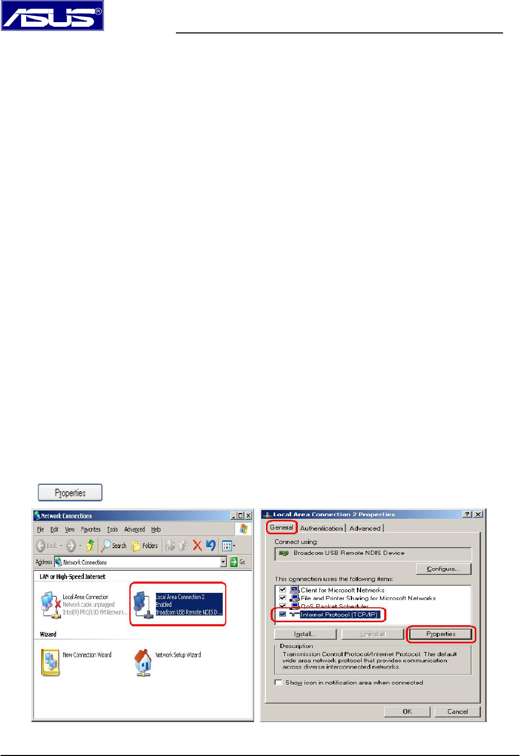
2. Double-click the Network Connections icon.
3. In the LAN or High-Speed Internet window, right-click on icon corresponding to your network interface card
(NIC) and select Properties. (Often this icon is labeled Local Area Connection). The Local Area Connection
dialog box displays with a list of currently installed network items.
4. Ensure that the check box to the left of the item labeled Internet Protocol (TCP/IP) is checked, and click
.
AAM6020VI ADSL Wireless Modem Router Quick Installation Guide
Page 5
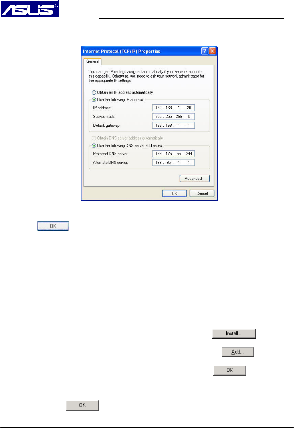
5. In the Internet Protocol (TCP/IP) Properties dialog box, click the radio button labeled Use the following IP
address and type 192.168.1.x (192.168.1.20 is shown below as an example), 255.255.255.0 and 192.168.1.1 in
the IP address field, Subnet Mask field and Default gateway, respectively.
TCP/IP Property @ Windows XP
6. Click twice to confirm your changes, and close the Control Panel.
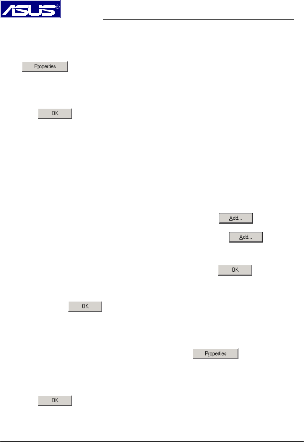
Windows® 2000 PCs:
1. In the Windows task bar, click the Start button, point to Settings, and then click Control Panel.
2. Double-click the Network and Dial-up Connections icon.
3. In the Network and Dial-up Connections window, right-click the Local Area Connection icon, and then
select Properties.
The Local Area Connection Properties dialog box displays with a list of currently installed network
components. If the list includes Internet Protocol (TCP/IP), the protocol has already been enabled, please skip
to step 10 directly.
4. If Internet Protocol (TCP/IP) does not display as an installed component, click .
5. In the Select Network Component Type dialog box, select Protocol, and then click .
6. Select Internet Protocol (TCP/IP) in the Network Protocols list, and then click .
You may be prompted to install files from your Windows 2000 installation CD or other media. Follow the
instructions to install the files.
7. If prompted, click to restart your computer with the new settings.
AAM6020VI ADSL Wireless Modem Router Quick Installation Guide
Page 6
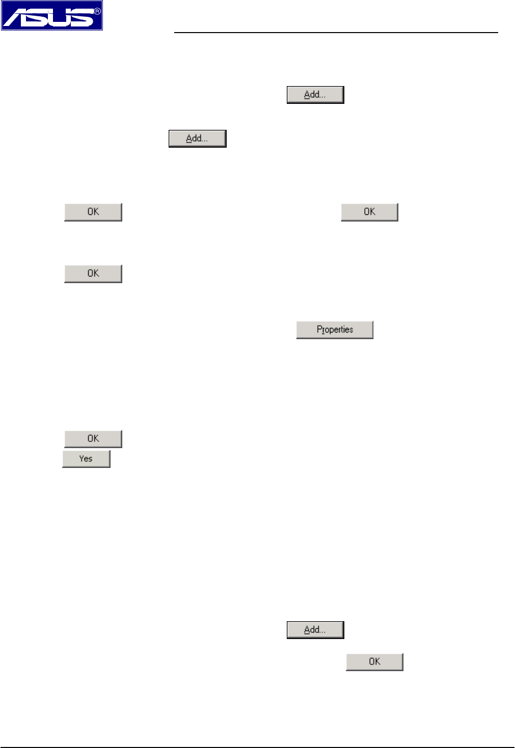
8. After restarting your PC, double-click the Network and Dial-up Connections icon in the Control Panel.
9. In Network and Dial-up Connections window, right-click the Local Area Connection icon, and then select
Properties.
10. In the Local Area Connection Properties dialog box, select Internet Protocol (TCP/IP), and then click
.
11. In the Internet Protocol (TCP/IP) Properties dialog box, click the radio button labeled Use the following IP
address and type 192.168.1.x, 255.255.255.0 and 192.168.1.1 in the IP address field, Subnet Mask field and
Default gateway, respectively.
12. Click twice to confirm and save your changes, and then close the Control Panel.
Windows® Me PCs
1. In the Windows task bar, click the Start button, point to Settings, and then click Control Panel.
2. Double-click the Network and Dial-up Connections icon.
3. In the Network and Dial-up Connections window, right-click the Network icon, and then select Properties.
The Network Properties dialog box displays with a list of currently installed network components. If the list
includes Internet Protocol (TCP/IP), the protocol has already been enabled, please skip to step 11 directly.
4. If Internet Protocol (TCP/IP) does not display as an installed component, click .
5. In the Select Network Component Type dialog box, select Protocol, and then click .
6. Select Microsoft in the Manufacturers box.
7. Select Internet Protocol (TCP/IP) in the Network Protocols list, and then click .
You may be prompted to install files from your Windows Me installation CD or other media. Follow the
instructions to install the files.
8. If prompted, click to restart your computer with the new settings.
9. After restarting your PC, double-click the Network and Dial-up Connections icon in the Control Panel.
10. In Network and Dial-up Connections window, right-click the Network icon, and then select Properties.
11. In the Network Properties dialog box, select TCP/IP, and then click .
12. In the TCP/IP Settings dialog box, click the radio button labeled Use the following IP address and type
192.168.1.x, 255.255.255.0 and 192.168.1.1 in the IP address field, Subnet Mask field and Default gateway,
respectively.
13. Click twice to confirm and save your changes, and then close the Control Panel.
Windows® 95, 98 PCs:
1. In the Windows task bar, click the Start button, point to Settings, and then click Control Panel.
AAM6020VI ADSL Wireless Modem Router Quick Installation Guide
Page 7
2. Double-click the Network icon.
The Network dialog box displays with a list of currently installed network components. If the list includes
TCP/IP, the protocol has already been enabled. Please skip to step 9 directly.
3. If TCP/IP does not display as an installed component, click . Then Select Network Component
Type dialog box will display.
4. Select Protocol, and then click .
The Select Network Protocol dialog box displays.
5. Click on Microsoft in the Manufacturers list box, and then click TCP/IP in the Network Protocols list box.
6. Click to return to the Network dialog box, and then click again.
You may be prompted to install files from your Windows 95/98 installation CD. Follow the instructions to install
the files.
7. Click to restart the PC and complete the TCP/IP installation.
8. After restarting your PC, open the Control Panel window, and then click the Network icon.
9. Select the network component labeled TCP/IP, and then click .
If you have multiple TCP/IP listings, select the listing associated with your network card or adapter.
10. In the TCP/IP Properties dialog box, click the IP Address tab.
11. Click the radio button labeled Use the following IP address and type 192.168.1.x,255.255.255.0 and
192.168.1.1 in the IP address field, Subnet Mask field and Default gateway, respectively.
12. Click twice to confirm and save your changes. You will be prompted to restart Windows. Please
click and restart your PC again.
Windows® NT 4.0 workstations:
1. In the Windows NT task bar, click the Start button, point to Settings, and then click Control Panel.
2. In the Control Panel window, double click the Network icon.
3. In the Network dialog box, click the Protocols tab.
The Protocols tab displays a list of currently installed network protocols. If the list includes TCP/IP, the protocol
has already been enabled. Please skip to step 9 directly.
4. If TCP/IP does not display as an installed component, click .
5. In the Select Network Protocol dialog box, select TCP/IP, and then click .
You may be prompted to install files from your Windows NT installation CD or other media. Follow the
instructions to install the files.
After all files are installed, a window displays to inform you that a TCP/IP service called DHCP can be set up to
dynamically assign IP information.
AAM6020VI ADSL Wireless Modem Router Quick Installation Guide
Page 8
6. Click to continue, and then click if prompted to restart your computer.
7. After restarting your PC, open the Control Panel window, and then double-click the Network icon.
8. In the Network dialog box, click the Protocols tab.
9. In the Protocols tab, select TCP/IP, and then click .
10. In the Microsoft TCP/IP Properties dialog box, click the radio button labeled Use the following IP address and
type 192.168.1.x, 255.255.255.0 and 192.168.1.1 in the IP address field, Subnet Mask field and Default gateway,
respectively.
11. Click twice to confirm and save your changes, and then close the Control Panel.
1.2 Building Wireless Connection Using A Wireless Interface
Most steps for accessing the modem are very similar to configure the wired NIC. Only difference
with wired NIC is that your wireless card has built wireless connection with modem already. We
will describe detailed linking and configuring steps, and take ASUS WL-100G 802.11G wireless
card for example as below.
1. Please make sure that you have well-installed wireless card driver and utility into your PC.
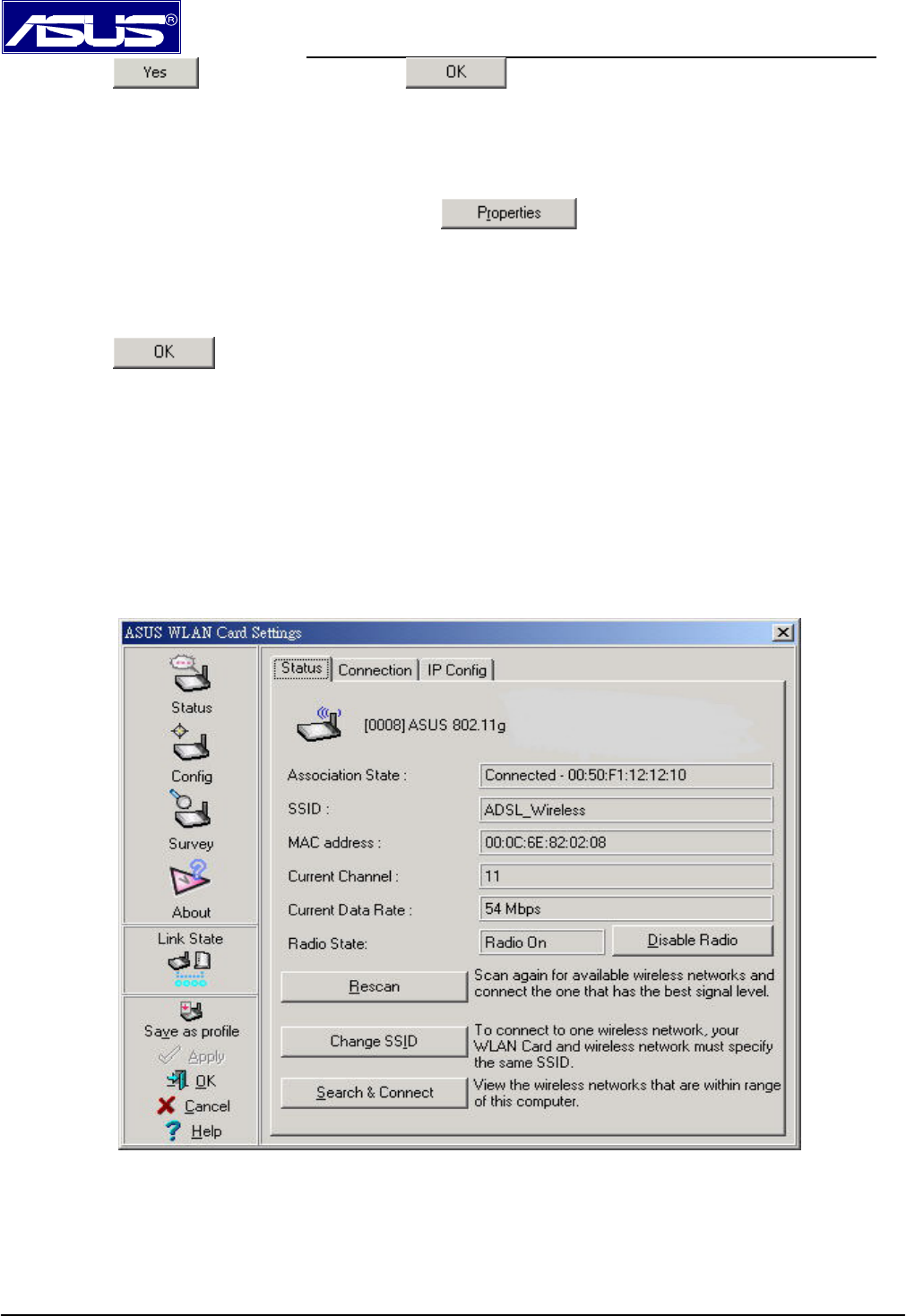
2. Run ASUS WLAN Control Center, you will find ASUS WLAN Setting screen.
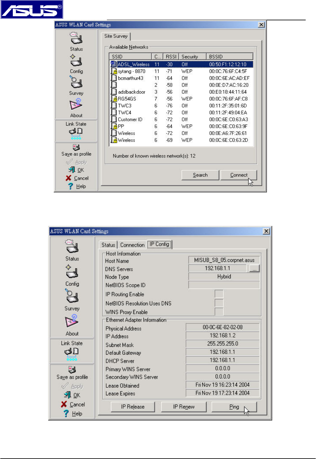
3. Click Survey icon on left column of Setting screen, you will find ADSL_Wireless - modem default SSID setting to
be showed on Available Network. Select ADSL_Wireless , than click Connect.
AAM6020VI ADSL Wireless Modem Router Quick Installation Guide
Page 9
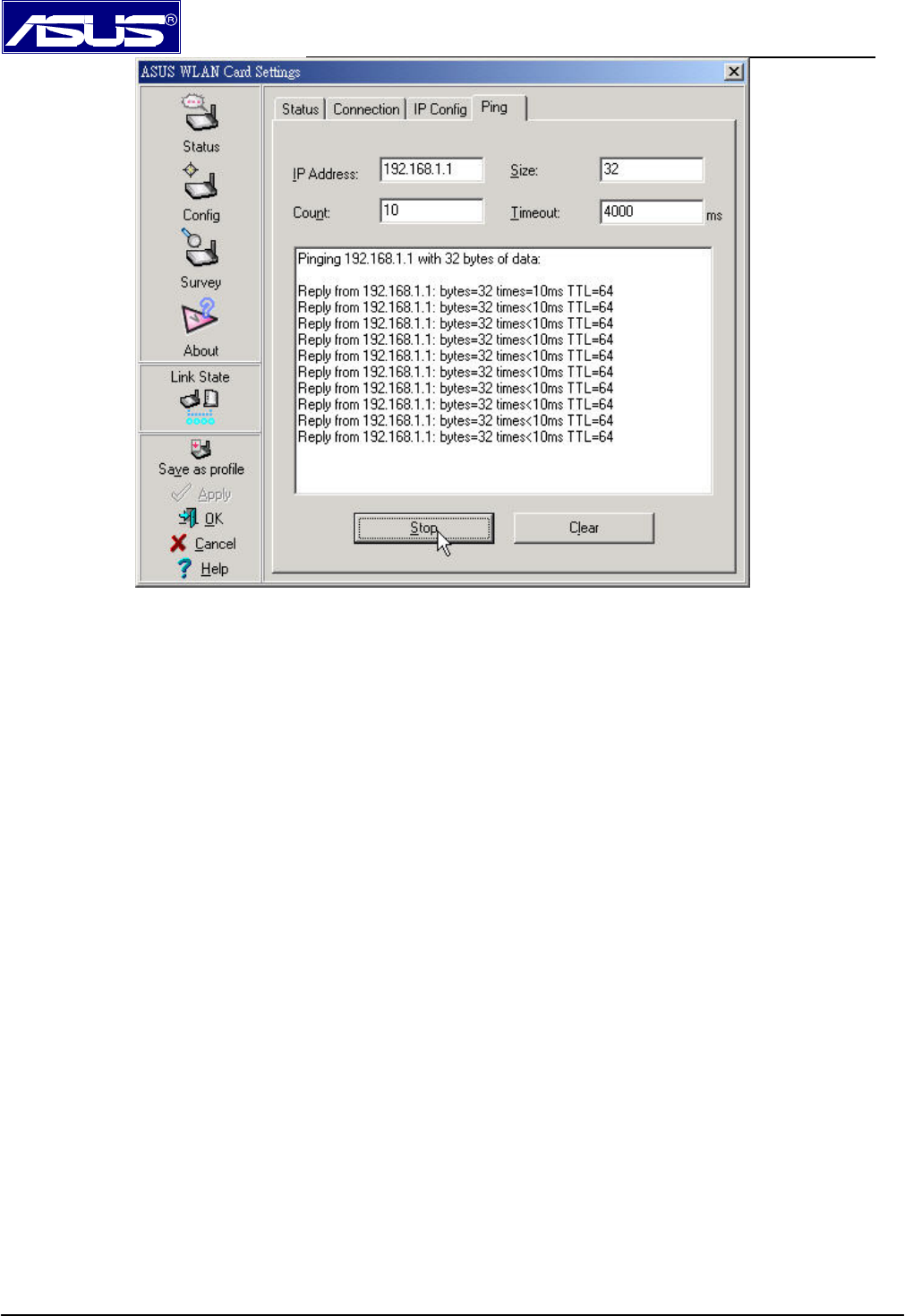
4. Click Status icon, then click IP Config to check IP address among 2~254 range. If it is true, then click Ping tab
and run ping to do connection test between modem with your PC.
AAM6020VI ADSL Wireless Modem Router Quick Installation Guide
Page 10
After finishing above steps, you are ready to login and start to configure modem now.
AAM6020VI ADSL Wireless Modem Router Quick Installation Guide
Page 11
2. Configuring Wireless Modem Router
2.1 Internet connection with NAT function:
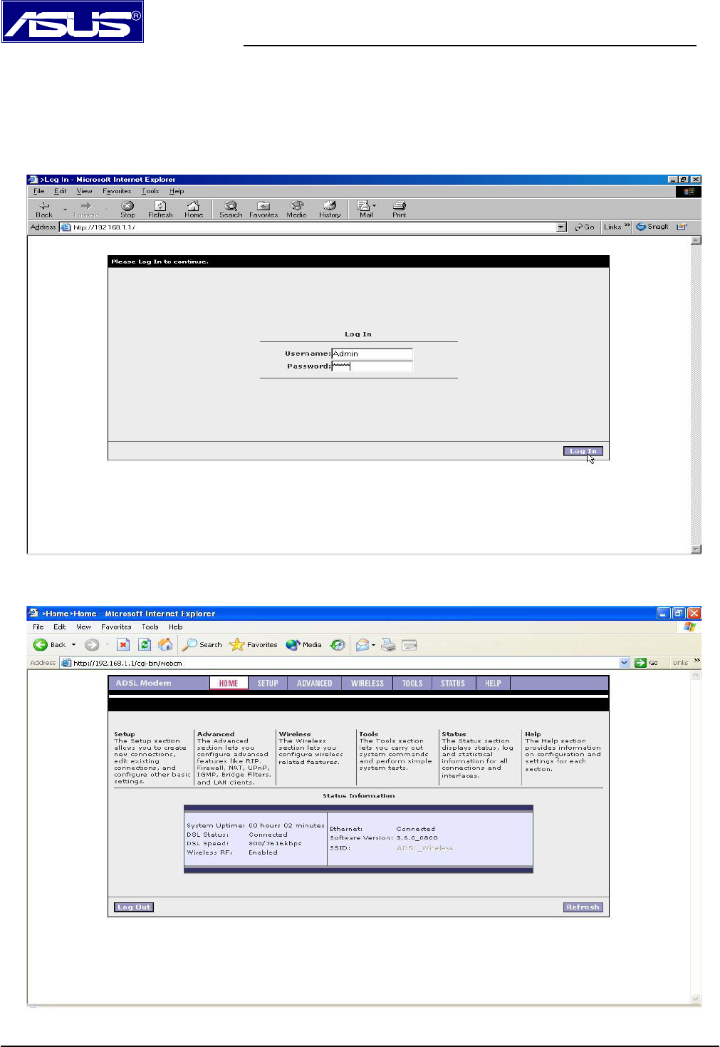
Please enter the modem’s default IP address http://192.168.1.1 into your PC’s web browser
and press Enter button on keyboard. The Login screen will show as below, following enter
Admin for Username and Admin for Password then click on Log In button.
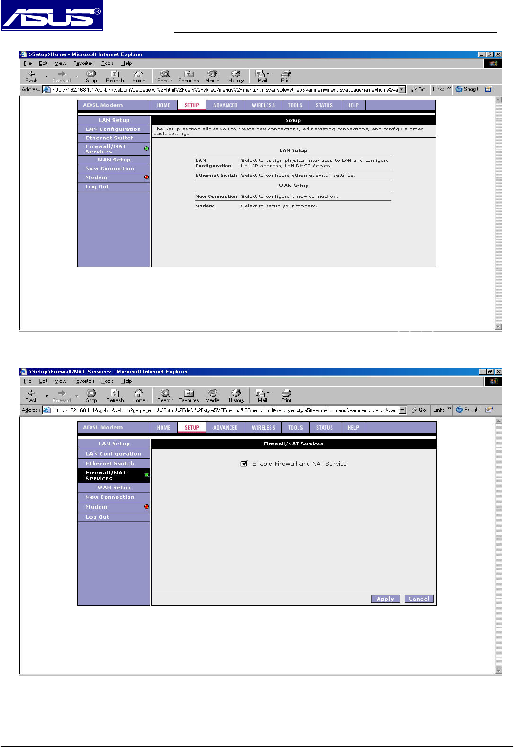
2.2 The ADSL modem home page will show as below, and it is divided into seven sections Ϋ
HOME, SETUP, ADVANCED, WIRELESS, TOOLS, STATUS and HELP.
AAM6020VI ADSL Wireless Modem Router Quick Installation Guide
Page 12
2.3 Click SETUP tab.
2.4 Click Firewall/NAT Services icon to select Enable Firewall and NAT Service, then click
on Apply tab. Now re-login modem again.
AAM6020VI ADSL Wireless Modem Router Quick Installation Guide
Page 13
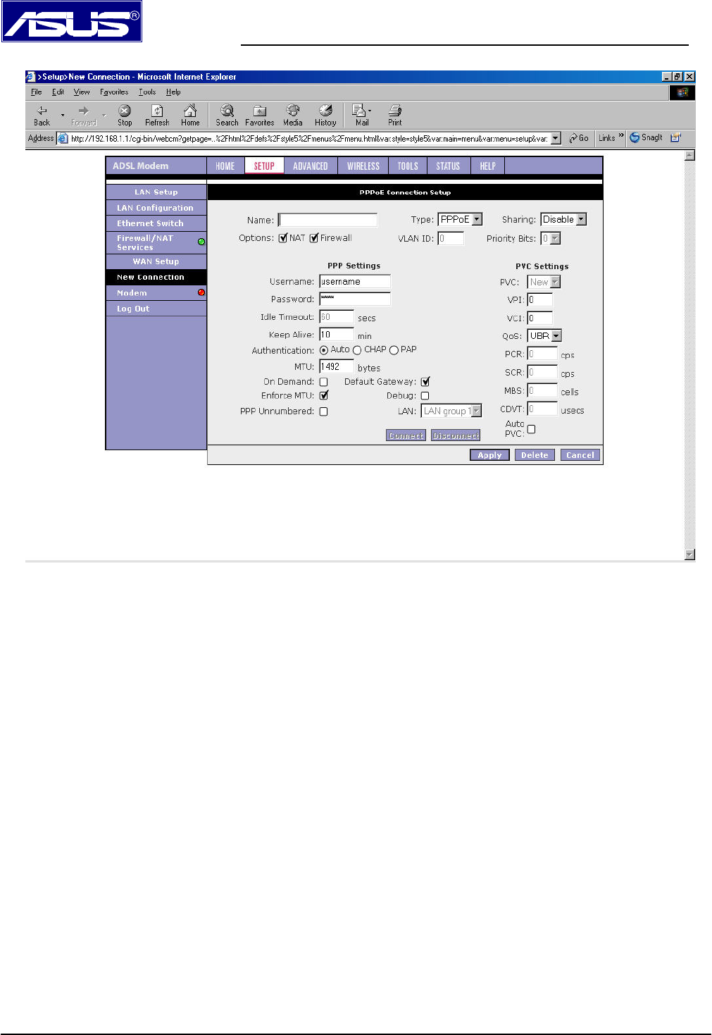
2.5 Click SETUPÆNew Connection tab.
2.6 Input data
Name column: It could be inputted anything you prefer.
Type: There are listed five selections which you can choose from Type item Ϋ PPPoE,
PPPoA, Static, DHCP and Bridge. Please select correct item which ISP gave you
PPP Settings:
Options: Select both NAT and Firewall functions.
Encapsulation: Please select correct encapsulation from your ISP, but it is except for PPPoE.
Username: Please input correct username which ISP gave you.
Password: Please input correct password which ISP gave you.
Keep Alive: Keep the default setting. If you want to change it, please input any number you
prefer.
MTU: Keep the default setting. If you want to change it, please get the correct number from
your ISP.
On Demand: If you have linking time-to-cost issue, please select this item and input number
into Idle Timeout column you prefer.
PVC Settings:
VPI: Please input correct number which ISP gave you.
VCI: Please input correct number which ISP gave you.
AAM6020VI ADSL Wireless Modem Router Quick Installation Guide
Page 14
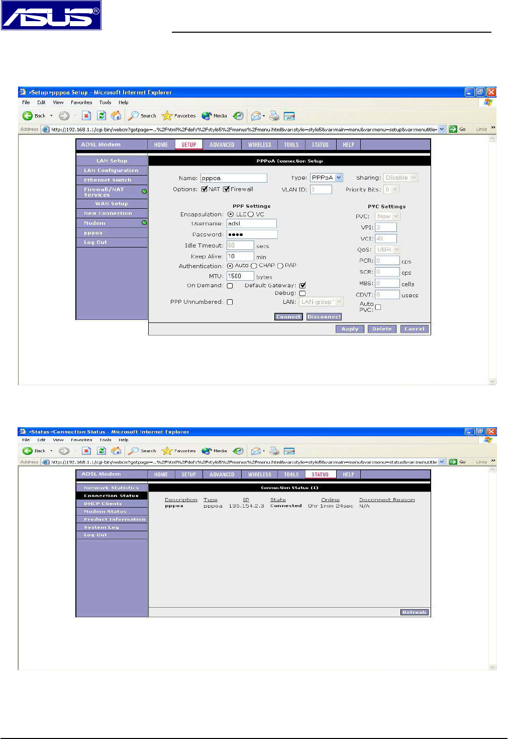
QoS: Keep the default setting.
Auto PVC: You also use this function to get correct VPI/VCI instead of inputting manually.
Please click on Apply icon.
2.7 Go to the Status tab, then click on Connection Status.
Under State of Connection Status, your WAN connection is now connected and you should be
able to link to enjoy internet services.
AAM6020VI ADSL Wireless Modem Router Quick Installation Guide
Page 15
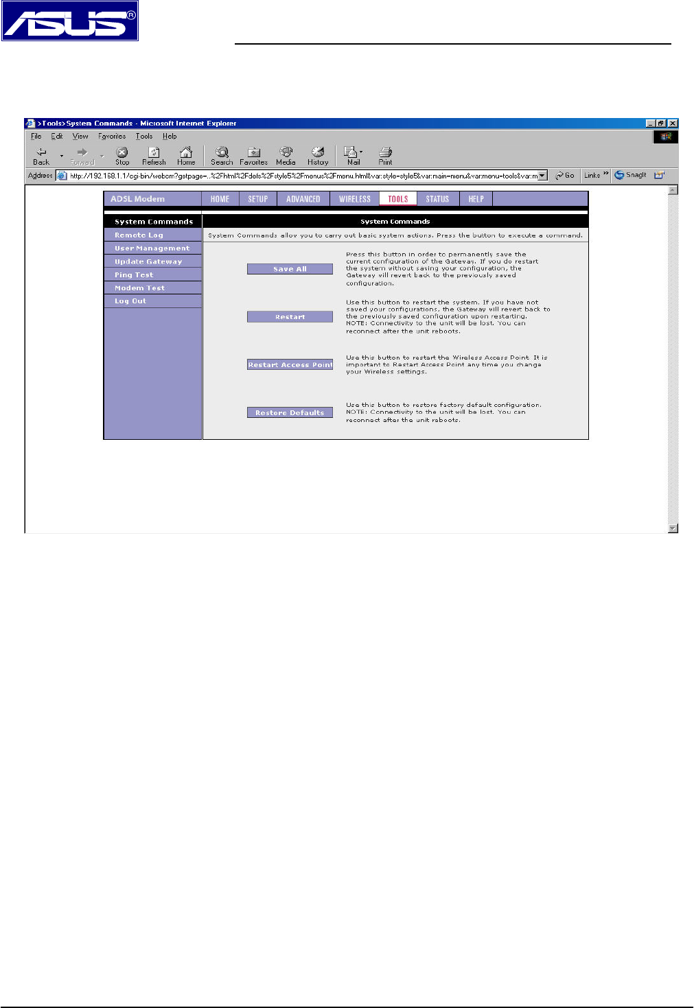
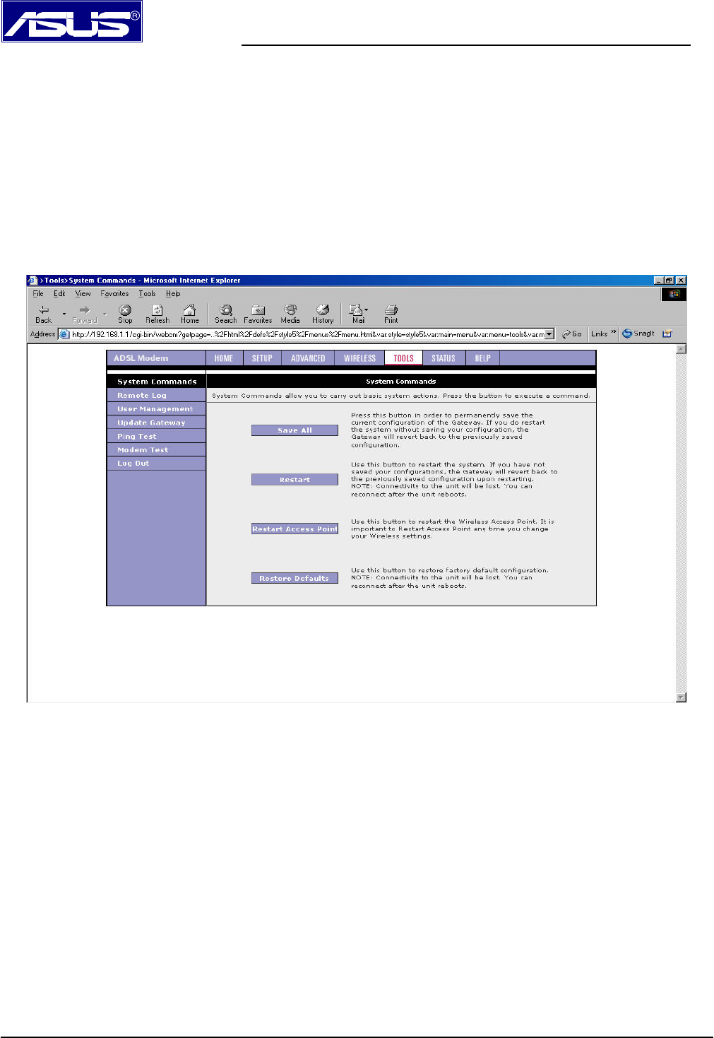
2.8 Click on Tools tab, then select System Commands. Please click on Save All, all of your
changes on settings will be saved into this unit; if you don’t run Save All process, you will lose
all changes you did once power off or restart modem.
AAM6020VI ADSL Wireless Modem Router Quick Installation Guide
Page 16
3. Performing a Factory Reset
There are two methods to perform a factory default settings on this unit Ϋ by software
management or reset manually.
3.1 Software Management:
Please first login into this unit using Username and Password, click on Tools Æ
System Commands. You will find a Restore Defaults tab is showed on the screen.
Use this button to restore factory default configurations. Connectivity to the unit will be
lost, you can build reconnection after the unit reboots.
3.2 Reset Manually:
If you experience extreme problem or forgot your password, please press the reset
button with a pencil tip till the status led goes off, then release the reset button. After
20 seconds, the led will come back on and all of settings will become to factory
defaults.
AAM6020VI ADSL Wireless Modem Router Quick Installation Guide
Page 17
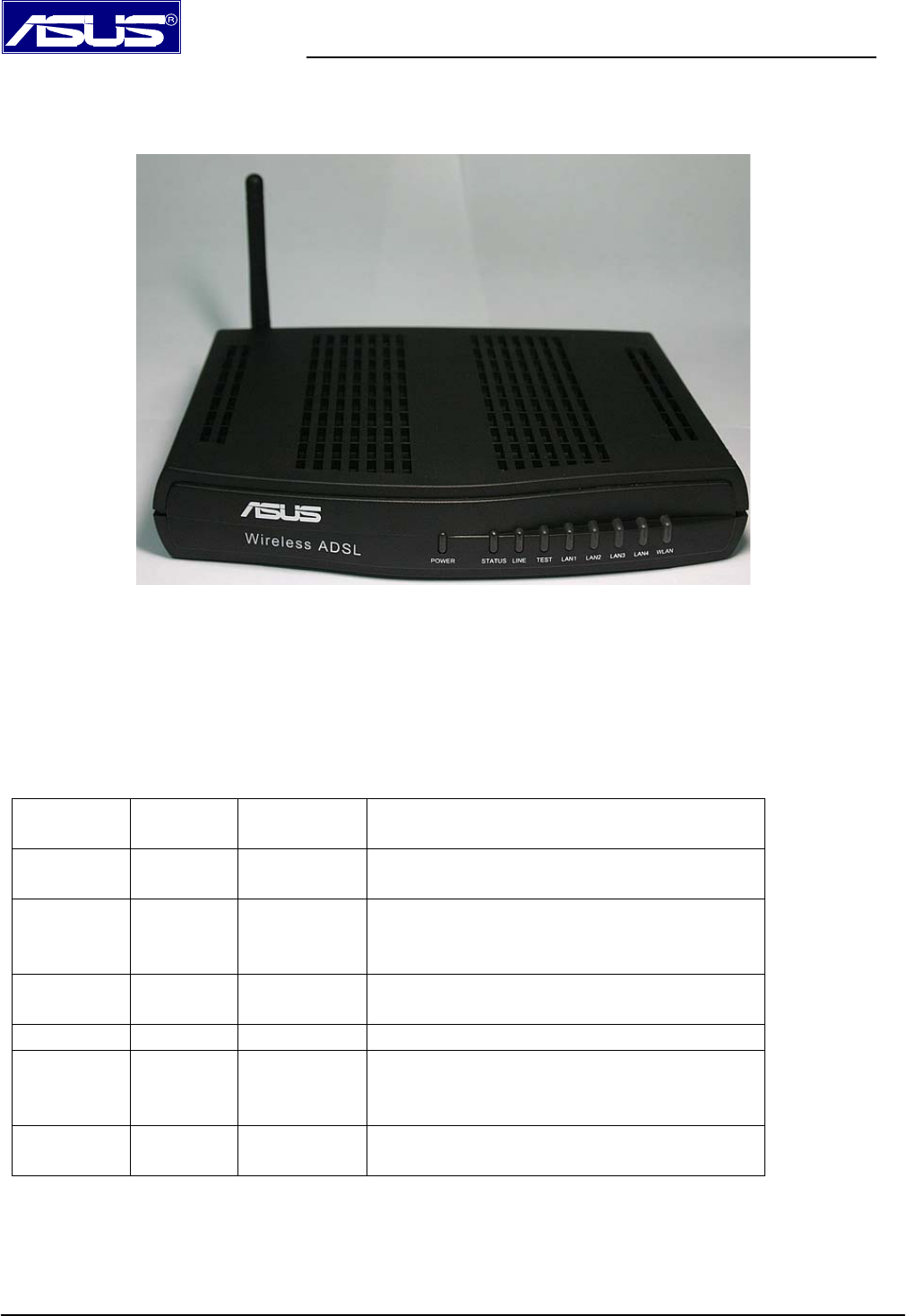
Front panel system messages
The following illustration shows the front panel of the ADSL Wireless Modem Router.
LED Indicators
The ADSL Wireless Modem Router is equipped with LEDs on the front panel as described in the
table below. (from left to right)
Label Color Status Description
POWER Red On
Off
Modem is powered ON
Modem is powered OFF
STATUS Blue On
Flashing
Off
ADSL link is established and active
Try to establish an ADSL connection
No ADSL link
LINE Blue Flashing Data transfer over ADSL line
TEST N/A N/A Status testing
LAN 1~4 Blue On
Flashing
Off
LAN link is established
Data transfer at LAN connection
No LAN link
WLAN Blue On
Off
Wireless AP is ON
Wireless AP is OFF
AAM6020VI ADSL Wireless Modem Router Quick Installation Guide
Page 18
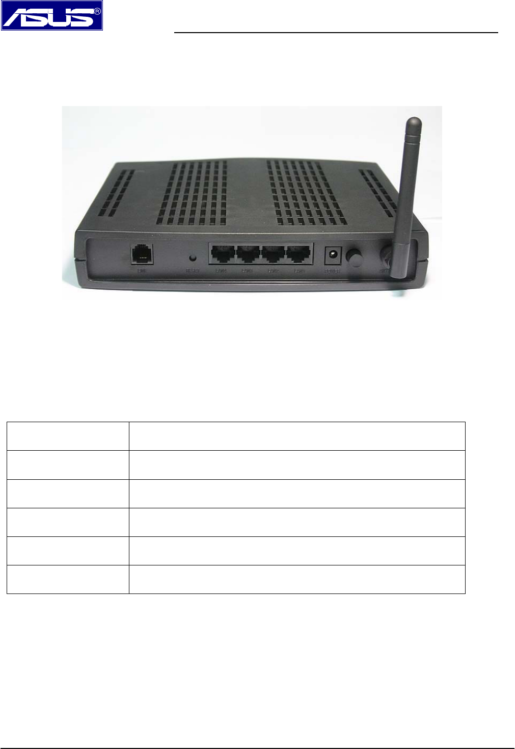
Rear panel system messages
The following illustration shows the rear panel of the ADSL Wireless Modem Router.
Outlet
The ADSL Wireless Modem Router is equipped with outlets on the rear panel as described in the table
below.
Label Function
LINE RJ-11 outlet, for ADSL line connector
RESET/DEFAULT Reset modem configuration to factory default settings
LAN 1~4 RJ-45 outlet for PC Ethernet port or hub/switch LAN connector
POWER For supplied power adapter connector
POWER SWITCH Power ON/OFF modem
===== End of AAM6020VI Quick Installation Guide =====

Appendix
FCC Warning Statement
This device complies with Part 15 of the FCC Rules. Operation is
subject to the following two conditions:
(1) this device may not cause harmful interference, and
(2) this device must accept any interference received, including
interference that may cause undesired operation.
This equipment has been tested and found to comply with thelimits for a class
B digital device, pursuant to part 15 of the FCC Rules. These limits are
designed to provide reasonable protection against harmful interference in a
residential installation. This equipment generates, uses and can radiate radio
frequency energy and, if not installed and used in accordance with the
instructions, may cause harmful interference to radio communications.
However, there is no guarantee that interference will not occur in a particular
installation. If this equipment does cause harmful interference to radio or
television reception, which can be determined by turning the equipment off and
on, the user is encouraged to try to correct the interference by one or more of
the following measures:
--- Reorient or relocate the receiving antenna.
--- Increase the separation between the equipment and receiver.
--- Connect the equipment into an outlet on a circuit different from that to which
the receiver is connected.
--- Consult the dealer or an experienced radio/TV technician for help.
Any changes or modifications not expressly approved by the party responsible
for compliance could void the user’s authority to operate the equipment.
This device and its antenna(s) must not be co-located or operating in
onjunction with any other antenna or transmitter
To maintain compliance with FCC’s RF exposure guidelines, this equipment
should be installed and operated with minimum distance 20cm between the
radiator and your body. Use on the supplied antenna.

Declaration of Conformity for R&TTE directive 1999/5/EC
Essential requirements – Article 3
Protection requirements for health and safety – Article 3.1a
Testing for electric safety according to EN 60950 has been conducted.
These are considered relevant and sufficient. Protection requirements for
electromagnetic compatibility – Article 3.1b
Testing for electromagnetic compatibility according to EN 301
489-1 and EN 301 489-17 has be en conducted. These are
considered relevant and sufficient.
Effective use of the radio spectrum – Article 3.2
Testing for radio test suites according to EN 300 328 has been
conducted. These are considered relevant and sufficient.
CE Mark Warning
This is a Class B product, in a domestic environment, this product
may cause radio interference, in which case the user may be
required to take adequate measures.