ASUSTeK Computer DCW625 Wireless Cable Gateway User Manual 16096620 DCW615 25 00 Cover
ASUSTeK Computer Inc Wireless Cable Gateway 16096620 DCW615 25 00 Cover
UserManual.wiki
>
ASUSTeK Computer
>
DCW625 User Manual
>
manual 1
Contents
1.
manual 1
2.
manual 2
manual 1
Navigation menu
Upload a User Manual
Namespaces
Wiki Guide
HTML
PDF
Info
Views
User Manual
Discussion / Help
Navigation
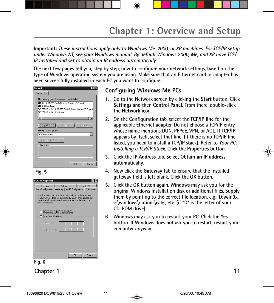
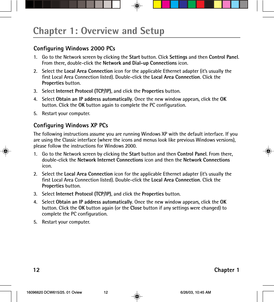
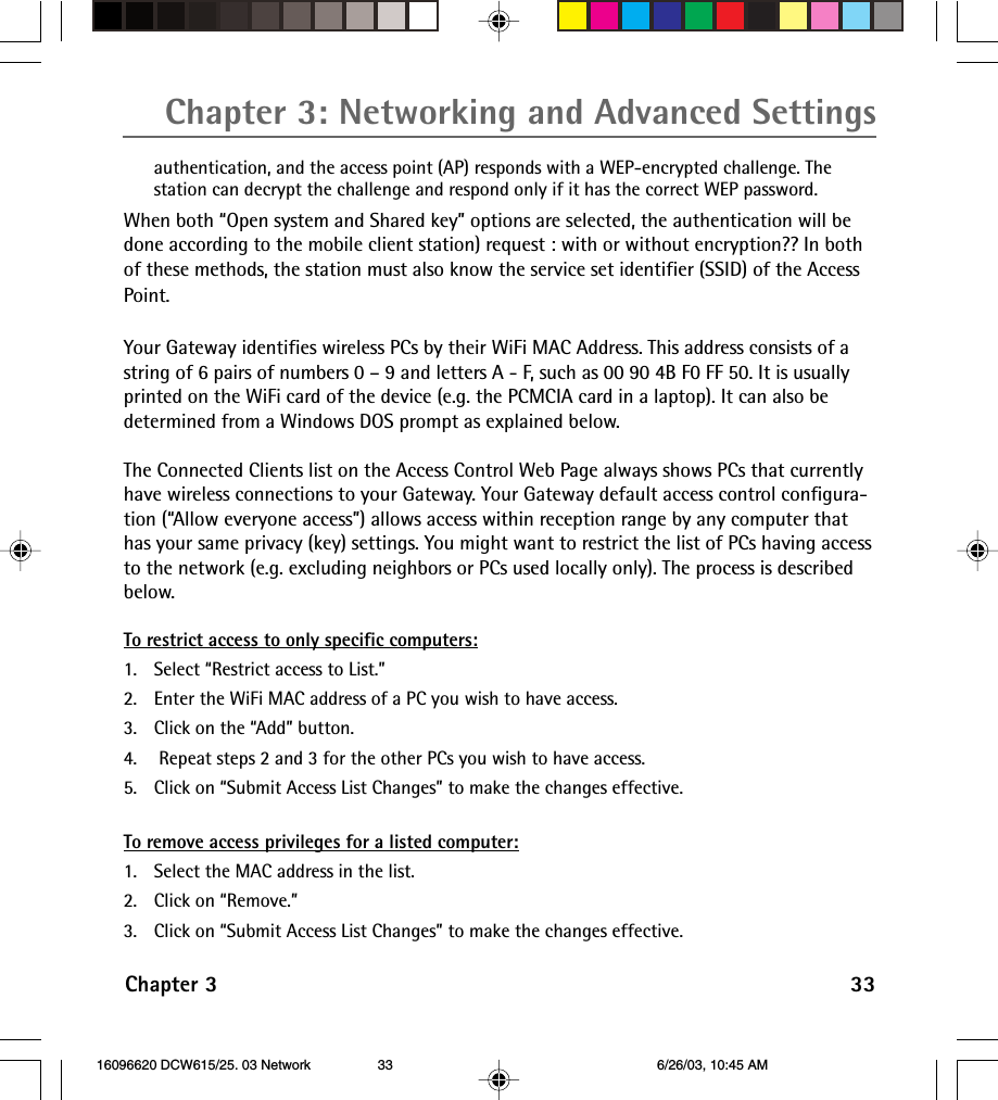
![Chapter 3: Networking and Advanced Settings34 Chapter 3Determining WiFi MAC Address (Fig. 35)If a printed WiFi MAC address for a PC cannot be found, itcan be determined as follows from the MS-DOS prompt inthe MS Windows running on that computer:1. Start MS-DOS. In Windows 98, this is “Start” ... “Run” ,,,[type in] “command” ... “OK”. In Windows Me, 2k and XP, thisis “Start” ... “Run” ... [type in] “cmd” ... OK.2. List your installed interfaces, by typing “ipconfig /all” andpressing “Enter.”3. Find the MAC address associated with the interfacedescription that matches your wireless card description. Inthis example, the phrase “802.11b PCMCIA” clearly identifiesthe WiFi card among the listed interfaces.Fig. 35 16096620 DCW615/25. 03 Network 6/26/03, 10:45 AM34](https://usermanual.wiki/ASUSTeK-Computer/DCW625.manual-1/User-Guide-349137-Page-36.png)