ASUSTeK Computer DCW625 Wireless Cable Gateway User Manual 16096620 DCW615 25 00 Cover
ASUSTeK Computer Inc Wireless Cable Gateway 16096620 DCW615 25 00 Cover
Contents
- 1. manual 1
- 2. manual 2
manual 1
010011110101110110111000
101010101011100110111011
10110110101100101111110
11010110110110011100111
011101001110111101101101
10101010101101101110010
0101101011101010011010
10111010110111100110100
0100101101001111010111
101010101011100110111011
10110110101100101111110
11010110110110011100111
011101001110111101101101
10101010101101101110010
0101101011101010011010
10111010110111100110100
010011110101110110111000
101010101011100110111011
10110110101100101111110
11010110110110011100111
011101001110111101101101
10101010101101101110010
Wireless Cable
Gateway
16096620 DCW615/25. 00 Cover 6/26/03, 10:45 AM1
CAUTION: Disconnect
power before servicing.
CAUTION: To ensure reliable operation and to prevent
overheating, provide adequate ventilation for this modem and
keep it away from heat sources. Do not locate near heat
registers or other heat-producing equipment. Provide for free
air flow around the cable modem and its power supply.
CABLE INSTALLER:
This reminder is provided to call your attention to Article 820-40 of the National Electrical Code
(Section 54 of the Canadian Electrical Code, Part 1) which provides guidelines for proper grounding
and, in particular, specifies that the cable ground shall be connected to the grounding system of the
building as close to the point of cable entry as practical.
DOCSIS compliant
This product was designed according to Data Over Cable Service Interface Specifications.
It will operate on any DOCSIS-compliant Hybrid Fiber Coax (HFC) cable system and offers DOCSIS
Baseline Privacy to promote secure Internet transactions.
Power cord Requirement
This product must be operated with the supplied line cord or with a line cord meeting IEC227 H03
VV-F or IEC227 H03 VVH2-F having conductors with a cross-sectional area not less than .75mm2.
Operating Information
Operating Temperature: 0˚ - 40˚ C (32˚ - 104˚ F)
Storage Temperature: -30˚ to 65˚ C
Power Pack
The power pack is intended to serve as mains disconnect device and so allows to turn off the cable
modem. This pack shall be easily accessible in an emergency
If you purchased this product at a retail outlet, please read the following:
Product Registration
Please fill out the product registration card that came with this product and return it immediately. Returning the card
allows us to contact you if needed.
Keep your sales receipt to obtain warranty parts and service and for proof of purchase. Attach it here and record the
serial and model numbers in case you need them. The numbers are located on the back of the product.
Model No. ____________________________________ Serial No _____________________________________________
Safety Information
16096620 DCW615/25. 00 Cover 6/26/03, 10:45 AM2

Table of Contents
1
Chapter 1: Overview and Setup
Introduction ................................................................................... 4
Wireless Cable Gateway Features .......................................................................... 4
What’s on the CD-ROM ............................................................................................ 5
Computer Requirements ........................................................................................... 6
Wireless Cable Gateway Overview............................................... 6
Contact Your Local Cable Company ...................................................................... 7
System Overview ........................................................................... 8
Your PC: Installing a PC Network Card ................................................................ 8
Your PC: Installing a TCP/IP Stack ......................................................................... 9
Your PC: Configuring DHCP on a TCP/IP Stack on a PC.................................10
Configuring Windows Me PCs .............................................................................. 11
Configuring Windows 2000 PCs ......................................................................... 12
Configuring Windows XP PCs .............................................................................. 12
Chapter 2: Connections and Setup
Connecting Your Devices ............................................................ 13
Ethernet Connection ............................................................................................... 13
USB Connecton ........................................................................................................ 13
Connecting the Cable Modem Using Windows Me for USB Connection 14
Activating the Wireless Cable Gateway.................................... 15
Initialization .............................................................................................................. 15
Buttons ....................................................................................................................... 16
Reset Switch ............................................................................................................. 17
Software Download Indicator .............................................................................. 17
Mandatory User Configuration .................................................. 18
TOC to be updated
16096620 DCW615/25. 00 TOC 6/26/03, 10:45 AM1

Table of Contents
2
Chapter 3: Networking and Advanced Settings
Advanced User Configuration .................................................... 10
Three Networking Modes ...................................................................................... 20
Status Web Page Group .............................................................. 21
Software Web Page ..................................................................................................21
Connection Web Page .............................................................................................21
Security Web Page .................................................................................................. 22
Diagnostics Web Page ............................................................................................ 22
Basic Web Page Group ................................................................ 23
Setup Web Page ....................................................................................................... 23
DHCP Web Page ....................................................................................................... 24
Advanced Web Page Group ........................................................ 25
Options Web Page ................................................................................................... 25
IP Filtering Web Page ............................................................................................. 26
MAC Filtering Web Page ........................................................................................ 26
Port Filtering Web Page ......................................................................................... 26
Forwarding Web Page ............................................................................................ 27
Port Triggers Web Page .......................................................................................... 27
DMZ Host Web Page ............................................................................................... 28
Routing Informaton Protocol Setup ................................................................... 28
Firewall Web Pages Group.......................................................... 29
Time of Day ............................................................................................................... 29
Web Filter Web Page .............................................................................................. 29
Event Log Web Page ............................................................................................... 30
Parental Control Web Pages Group .................................................................... 30
Wireless Web Pages Group ......................................................... 31
16096620 DCW615/25. 00 TOC 6/26/03, 10:45 AM2

Table of Contents
3
Enable Web Page ......................................................................................................31
Basic Web Page .........................................................................................................31
Privacy Web Page .....................................................................................................31
Advanced Web Page ............................................................................................... 32
Access Control Page ................................................................................................ 32
Determining Wifi MAC address ................................................. 34
Chapter 4: Additional Information
Troubleshooting ........................................................................... 35
Front of the Unit (DCW615) ..................................................... 36
Front of the Unit (DCW625/TCW690) ..................................... 37
Back of the Unit (DCW615) ...................................................... 38
Back of the Unit (DCW625/TCW690) ...................................... 39
Detailed Explanation of Jacks.................................................... 40
Care and Cleaning ....................................................................... 41
Service Information .................................................................... 41
FCC Declaration of Conformity and Industry
Canada Information .................................................................... 42
Additional FCC Information ....................................................... 43
Product Specifications ................................................................ 45
TOC to be updated
16096620 DCW615/25. 00 TOC 6/26/03, 10:45 AM3

Chapter 1: Overview and Setup
Illustrations contained in this document are for representation only.
4Chapter 1
Introduction
Wireless Cable Gateway Features
Thank you for purchasing the Wireless Cable Gateway. This device delivers the highest
performance in data over cable technology. Ideal for home and small business users, this easy-to-
use communication device offers reliable connectivity as well as remarkable data transfer rates—
up to 600 times faster than a 56K dial-up modem. Once the gateway is activated, you are online
to enjoy real-time 3D animation, video conferencing, and perform other data intensive tasks.
The Wireless Cable Gateway provides high-speed, reliable and secure transport capabilities and is
designed with DOCSIS upgrade ability for both DOCSIS 1.0 and 1.1. The gateway offers anti-
spoofing functions, resulting in greater subscriber privacy and higher system availability.
Advanced features such as HomePNA2.0, WLAN IEEE 802.11b, NAT, Firewall, VPN pass through and
CableHome are also available now and can be configured.
16096620 DCW615/25. 01 Oview 6/26/03, 10:45 AM4

Chapter 1 5
Chapter 1: Overview and Setup
What’s on the CD-ROM
If you connect a PC using the USB port on your gateway, you’ll need the USB drivers found on the
CD-ROM.
CD-ROM Contents:
•Electronic copy of this user’s guide (.pdf format)
•Adobe Acrobat Reader — application you can load to read .pdf format, if you don’t have it
loaded already
•USB drivers — required if connecting by USB
16096620 DCW615/25. 01 Oview 6/26/03, 10:45 AM5
6Chapter 1
Chapter 1: Overview and Setup
Computer Requirements
•USB 1.0 or 1.1 (PC only), Ethernet (10/100), 802.11b, or HPNA 1.0 or 2.0 connectivity
•A TCP/IP network protocol for each machine
•A network cable with RJ-45 connector for Ethernet connection
• Microsoft Internet Explorer 4.0 or later, or Netscape Navigator 4.0 or later. (5.0 and 4.7 or
later, respectively, are strongly recommended.)
•Windows Me, 2000, or XP for USB
Wireless Cable Gateway Overview
Cable Internet Service Requirements
•Cable company that offers DOCSIS-compliant Internet services
What the Wireless Cable Gateway Does
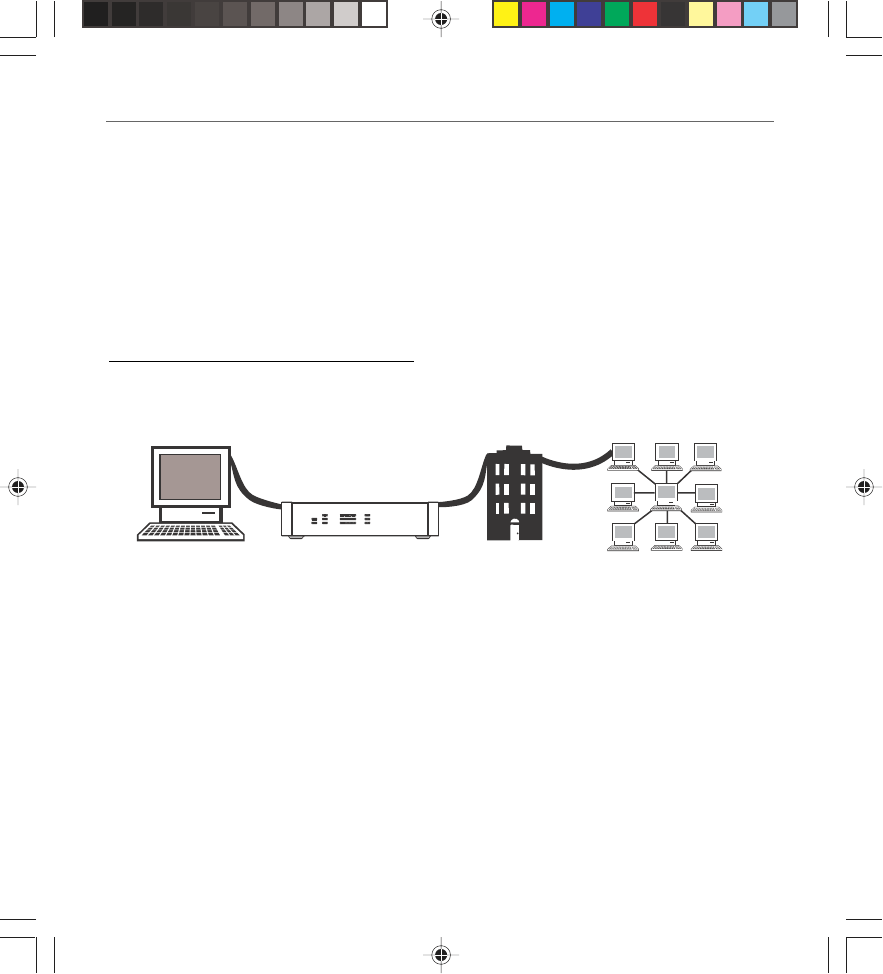
The Digital Wireless Cable Gateway serves as a two-way high-speed bridge between your personal
computer and a cable Internet Service Provider (ISP). It converts information that originates from
the Internet or your computer into electronic messages that can be transported over the same
wires your cable company uses to transport video signals.
What the Wireless Cable Gateway Needs to Do Its Job
•The Right Cable Company: Make sure your cable company provides data services that use
cable TV industry-standard DOCSIS technology.
•The Internet Service Provider (ISP): Your cable company provides you access to an Internet
Service Provider (ISP). The ISP is your gateway to the Internet. It provides you with a pipeline
to access Internet content on the World Wide Web (WWW).
Computer Internet
Wirelesss Cable Gateway Cable Company
HPNA
WLAN
Power
Test
USB
Full/Col
100/10
Link/Act
Receive
Send
Ready
Link/Act Cable Modem
1 2 3 4
16096620 DCW615/25. 01 Oview 6/26/03, 10:45 AM6
Chapter 1 7
Chapter 1: Overview and Setup
Check with your cable company to make sure you have everything you need to begin; they’ll
know if you need to install special software or re-configure your computer to make your
cable Internet service work for you.
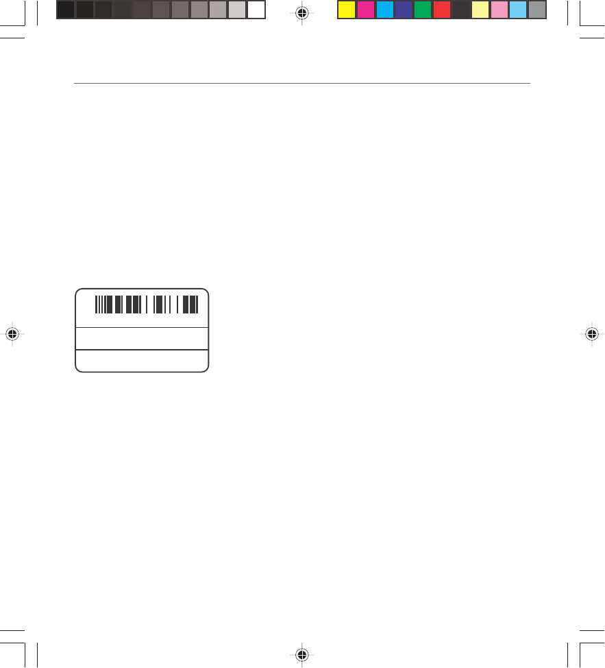
Contact Your Local Cable Company
You will need to contact your cable company to establish an Internet account before you can use
your gateway. You should have the following information ready (which you will find on the
sticker on the gateway) :
•The serial number
•The model number
•The Media Access Control (MAC) address
Record your information here:
Serial Number: _________________________
Model Number: _________________________
MAC Address: __________________________
Please verify the following with the cable company:
S.N.
MODEL:
MAC:
XXXXXXXXXXXXXX
DCWXXX
009064XXXXXX
•The cable service to your home supports DOCSIS-compliant two-way modem access.
•Your Internet account has been set up.
•You have a cable outlet near your PC and it is ready for cable modem service.
Note: It is important to supply power to the modem at all times. Keeping your modem plugged in will keep it
connected to the Internet. This means that it will always be ready when you are. To disconnect your computer
from the Internet, use the ON/OFF button to put the modem in standby mode.
Important Information
Your cable company should always be consulted before installing a new cable outlet. Do not
attempt any rewiring without contacting your cable company first.
16096620 DCW615/25. 01 Oview 6/26/03, 10:45 AM7

8Chapter 1
Chapter 1: Overview and Setup
System Overview
The Wireless Cable Gateway is connected between your cable company and the PCs within your
home, as pictured previously in the Wireless Cable Gateway Overview. The connection to the cable
company is made by a coaxial cable, and is referred to as the WAN (Wide Area Network) side of
your Wireless Cable Gateway. The connections to your PCs are made by your choice of several
standard home networking methods: Ethernet, USB, or 802.11g Wireless. These are referred to as
the LAN (Local Area Network) side of your Wireless Cable Gateway. Multiple PCs can use any or all
of the LAN side connections simultaneously to share your single cable company connection, up to
a maximum of 254 PCs total.
Unlike a simple hub or switch, the gateway’s setup consists of more than simply plugging
hardware together. You’ll need to configure your networked PCs to accept the IP addresses the
gateway assigns them (if applicable), and you will also need to configure the gateway with
settings provided by your cable company.
This installation guide takes you through all the necessary steps for easy installation. Please refer
to the troubleshooting section for any improper behavior.
Even if you consider to use the gateway in a wireless mode only, it is highly recommended to
perform all the settings through a wired connection: USB or Ethernet first.
• If you intend to connect the Gateway though USB, please go to Chapter 2, USB Connection,
page XX.
• If you intend to connect the Gateway though Enternet, please go to Chapter 2, Ethernet
Connection, page XX.
•If you already have a network card, follow the next section.
Your PC: Installing a PC Network Card
If your PC does not already support Ethernet or USB, you must install a network interface card.
Following is an example setup procedure:
1. Install an Ethernet card on your motherboard, following the card’s directions.
2. Power up your PC and follow the Add New Hardware Wizard’s instructions to install the
driver. When asked to restart your computer at the end of the installation, click Yes.
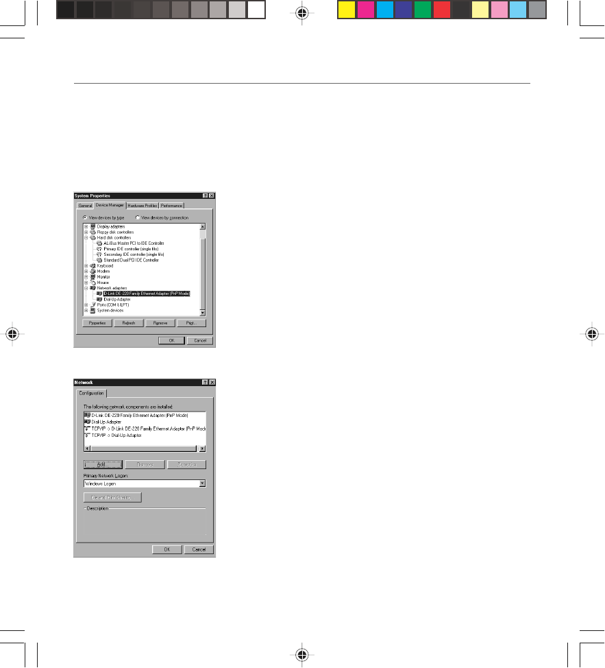
3. After restarting the system, right-click My Computer on the desktop, select Properties, click
the Device Manager tab, and then double-click Network adapters to confirm that the
Ethernet driver is properly installed.
16096620 DCW615/25. 01 Oview 6/26/03, 10:45 AM8
Chapter 1 9
Chapter 1: Overview and Setup
Your PC: Installing a TCP/IP Stack
Follow these instructions to install the TCP/IP protocol stack on one of your PCs only after a
network card has been successfully installed inside the PC. These instructions are for Windows Me.
For TCP/IP setup under Windows NT, 2000, and XP, refer to your Windows documentation.
1. Click the Start button. Choose Settings and then Control Panel.
2. Double-click on the Network icon to bring up your
Network window. Select the Configuration tab.
3. Click the Add button.
4. Double-click on Protocol.
Fig. 1
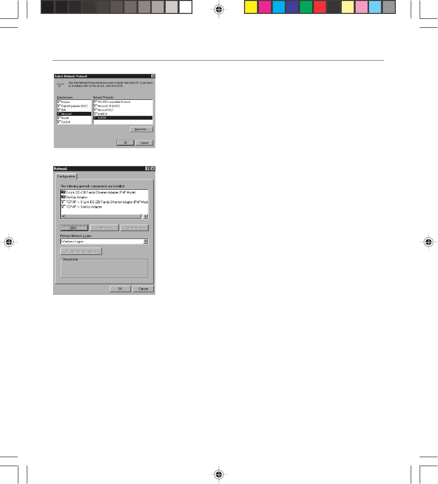
5. Highlight Microsoft under the list of manufacturers.
6. Find and double-click TCP/IP in the list to the right (see
Figure 9).
Fig. 2
16096620 DCW615/25. 01 Oview 6/26/03, 10:45 AM9
10 Chapter 1
Chapter 1: Overview and Setup
Fig. 3
Fig. 4
7. After a few seconds, the main Network window will appear.
The TCP/IP Protocol should now be listed.
8. Click the OK button again. Windows may ask you for the
original Windows installation disk or additional files. Supply
them by pointing to the correct file location, e.g., D:\win9x,
c:\windows\options\cabs, etc. (if “D” is the letter of your
CD-ROM drive).
9. Windows will ask you to restart the PC. Click the Yes
button.
The TCP/IP installation is now complete.
Your PC: Configuring DHCP on a TCP/IP Stack on a PC
These instructions will help you configure each of your computers to be able to communicate
with the gateway to obtain an IP (or TCP/IP) address automatically (called DHCP, Dynamic Host
Configuration Protocol).
Find out which operating system your computer is running by clicking the Start button and then
going to the Settings option. Then click Control Panel and double-click the System icon. If your
Start menu doesn’t have a Settings option, you’re running Windows XP. Click the Cancel button
when done.
You may need to do this for each computer you are connecting to the gateway.
16096620 DCW615/25. 01 Oview 6/26/03, 10:45 AM10
Chapter 1 11
Chapter 1: Overview and Setup
Important: These instructions apply only to Windows Me, 2000, or XP machines. For TCP/IP setup
under Windows NT, see your Windows manual. By default Windows 2000, Me, and XP have TCP/
IP installed and set to obtain an IP address automatically.
The next few pages tell you, step by step, how to configure your network settings, based on the
type of Windows operating system you are using. Make sure that an Ethernet card or adapter has
been successfully installed in each PC you want to configure.
Configuring Windows Me PCs
1. Go to the Network screen by clicking the Start button. Click
Settings and then Control Panel. From there, double-click
the Network icon.
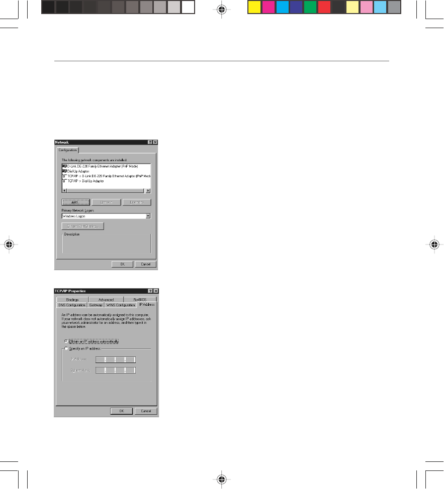
2. On the Configuration tab, select the TCP/IP line for the
applicable Ethernet adapter. Do not choose a TCP/IP entry
whose name mentions DUN, PPPoE, VPN, or AOL. If TCP/IP
appears by itself, select that line. (If there is no TCP/IP line
listed, you need to install a TCP/IP stack). Refer to Your PC:
Installing a TCP/IP Stack. Click the Properties button.
3. Click the IP Address tab. Select Obtain an IP address
automatically.
4. Now click the Gateway tab to ensure that the Installed
gateway field is left blank. Click the OK button.
5. Click the OK button again. Windows may ask you for the
original Windows installation disk or additional files. Supply
them by pointing to the correct file location, e.g., D:\win9x,
c:\windows\options\cabs, etc. (if “D” is the letter of your
CD-ROM drive).
6. Windows may ask you to restart your PC. Click the Yes
button. If Windows does not ask you to restart, restart your
computer anyway.
Fig. 6
Fig. 5
16096620 DCW615/25. 01 Oview 6/26/03, 10:45 AM11

12 Chapter 1
Chapter 1: Overview and Setup
Configuring Windows 2000 PCs
1. Go to the Network screen by clicking the Start button. Click Settings and then Control Panel.
From there, double-click the Network and Dial-up Connections icon.
2. Select the Local Area Connection icon for the applicable Ethernet adapter (it’s usually the
first Local Area Connection listed). Double-click the Local Area Connection. Click the
Properties button.
3. Select Internet Protocol (TCP/IP), and click the Properties button.
4. Select Obtain an IP address automatically. Once the new window appears, click the OK
button. Click the OK button again to complete the PC configuration.
5. Restart your computer.
Configuring Windows XP PCs
The following instructions assume you are running Windows XP with the default interface. If you
are using the Classic interface (where the icons and menus look like previous Windows versions),
please follow the instructions for Windows 2000.
1. Go to the Network screen by clicking the Start button and then Control Panel. From there,
double-click the Network Internet Connections icon and then the Network Connections
icon.
2. Select the Local Area Connection icon for the applicable Ethernet adapter (it’s usually the
first Local Area Connection listed). Double-click the Local Area Connection. Click the
Properties button.
3. Select Internet Protocol (TCP/IP), and click the Properties button.
4. Select Obtain an IP address automatically. Once the new window appears, click the OK
button. Click the OK button again (or the Close button if any settings were changed) to
complete the PC configuration.
5. Restart your computer.
16096620 DCW615/25. 01 Oview 6/26/03, 10:45 AM12

Chapter 2: Connections and Setup
Chapter 2 13
Illustrations contained in this document are for representation only.
Connecting Your Devices
Ethernet Connection
1. Before you begin, make sure that all of your hardware is powered off, including the gateway,
PCs, hubs, and switches.
2. Connect one end of an Ethernet cable to one of the Ethernet ports on the back of the
gateway and the other end to a standard port on a network device, e.g., a PC, print server,
hub, or switch.
3. Connect the coaxial cable from the wall to the CABLE jack on the back of the gateway.
4. Connect the power supply cable to the Power jack on the back of the gateway, then plug the
supplied power cable into an AC power outlet. Go to section, Activating the Wireless Cable
Gateway, page 15.
USB Connection
The cable modem CD included with your modem contains the drivers and other information you
need to install your cable modem. Follow instructions 1 through 5 to connect the cable modem to
the USB port on your computer. Instructions must be followed in the order they appear.
1. Connect one end of the coaxial cable to the cable connection in the wall. Attach the other
end of the coaxial cable to the connector on the cable modem labeled “CABLE” (Fig. 2) on
page 8
2. Insert the plug from the AC power supply into the power AC jack on cable modem and the
two-prong plug into the AC outlet.
3. Insert the supplied cable modem CD-ROM. Wait momentarily fo rthe cable modem CD
window display.
4. Close all open appplications and dialog boxes, including the cable modem CD window.
Note: Open applications may interfere with your cable modem installation.
5. Connect one end of the USB cable to the USb port located on the back of your conmputer.
Connect the other end of the USB cable to the USB port on the cable modem’s back panel.
Note: Use only the power supply that accompanied this unit. Using pther power supplies
may damage the unit. Next, you need to install the USB drivers for your operation system,
(Installation for Windows Me is described hereafter:)
16096620 DCW615/25. 02 Connect 6/26/03, 10:45 AM13
14 Chapter 2
Chapter 2: Connections and Setup
Connecting the Cable Modem Using Windows Me for USB Connection
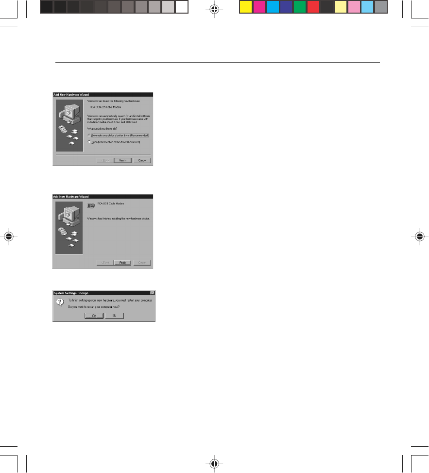
6. Windows Me will briefly disply the “found New Hardware
Wizard,” and automatically proceed to the “add New
Hardware Wizard” (Fig. 7).
Choose the Automatic search for a better driver
(Recoomend)” otpion, and click “Next.”
Note: If Windwos Me does not recognize the cable
modem’s presence, i.e., the “add New hardware Wizard”
did not automatically appear, your BIOS settings may not
permit USB and/or Plug-and-Play devices. Pelase contact
your comptuer’s customer service department.
Fig. 8
Fig. 7
7. The automatic search should find and install the driver for
the “RCA or Thomson USB Cable Modem” (Fig.8). Click on
“Finish’ to complete the process.
8. When the “System Settings Change” window appears, click
“Yes” to restart your computer (Fig. 9).
9. The Thomson cable modem installation is now complete. To validate a proper installation, perform
the following instructions.
• Click on “Start” icon in the lower left-hand corner of your screen.
•Select “Settings,” followed by “Control Panel.” The “Control Panel” window appears.
•Double-click on the “System” icon, and select the “Device Manager.”
Fig. 9
16096620 DCW615/25. 02 Connect 6/26/03, 10:45 AM14
Chapter 2 15
Chapter 2: Connections and Setup
•Scroll down the list until you come to “Network Adapters.” Double-click on “Network
Adapters.”
•The “RCA or Thomson USB Cable Modem” should exist. If ‘RCA or Thomson USB Cable
Modem” does not exist, the cable modem was NOT installed correctlly. Uninstall the drivers
and start the process again.
Activating the Wireless Cable Gateway
Initialization
Turn on the gateway’s POWER switch (DCW615) or the ON/OFF button on the front (DCW625/
TCW690). The Power indicator on the front of the unit comes on.
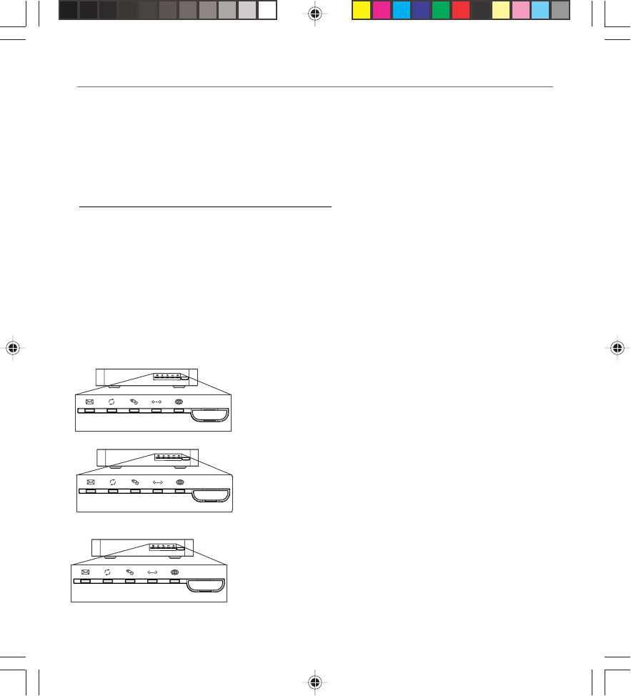
Initialization Modes
After you install the cable modem and turn it on for the first time (and each time the modem is
reconnected to the power), it goes through five steps before it can be used. Each of these steps is
represented by a different pattern of flashing lights on the front of the modem.
Note: All indicators flash once prior to the initialization sequence.
Internet On/Off
Cable
Activity Cable
Link
Message PC Link Internet
Internet On/Off
Cable
Activity Cable
Link
Message PC Link Internet
x
1. Tuning – The cable modem is functional and searching for
a downstream cable modem service channel on your cable
system.
2. Ranging – The modem is now tuned to a downstream cable
modem channel and can now receive data. Now it searches
for an upstream channel so that it can send data.
3. Connecting – The cable modem is now commun-icating
start-up data both down-stream and upstream.
The cable company is establishing IP connectivity with your
modem.
Internet On/Off
Cable
Activity Cable
Link
Message PC Link Internet
Internet On/Off
Cable
Activity Cable
Link
Message PC Link Internet
x
x
Internet On/Off
Cable
Activity Cable
Link
Message PC Link Internet
Internet On/Off
Cable
Activity Cable
Link
Message PC Link Internet
x
x
x
16096620 DCW615/25. 02 Connect 6/26/03, 10:45 AM15
16 Chapter 2
Chapter 2: Connections and Setup
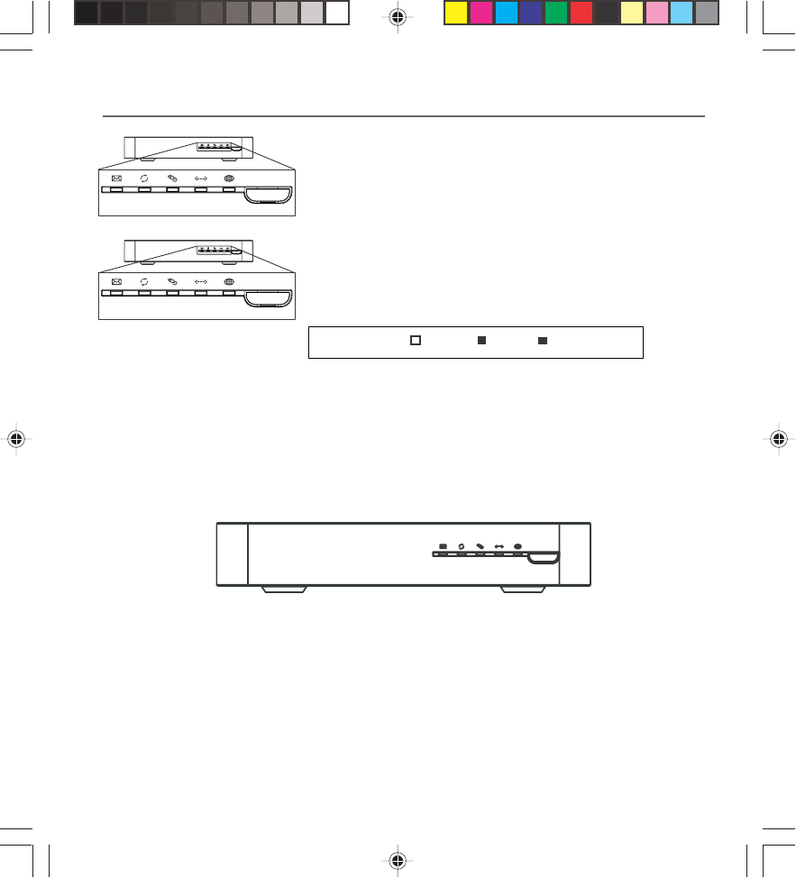
4. Configuring – The cable modem received its IP address and
is downloading its configuration file from the Internet
Service Provider (ISP).
Internet On/Off
Cable
Activity Cable
Link
Message PC Link Internet
Internet On/Off
Cable
Activity Cable
Link
Message PC Link Internet
x
x
xx
Internet On/Off
Cable
Activity Cable
Link
Message PC Link Internet
Internet On/Off
Cable
Activity Cable
Link
Message PC Link Internet
x
x
xx
x
5. Registering – The cable modem configuration is complete.
It is registering its “as-configured” settings with your Cable
Operator. Once complete, the POWER (INTERNET)*, PC LINK,
and CABLE (CABLE ACTIVITY)* indicators stop flashing and
remain on.
Internet On/Off
Cable
Activity Cable
Link
Message PC Link Internet
INTERNET* – Indicates whether the Internet Connection is active.
CABLE LINK* – Indicates the status of your cable connection. The light is off when no cable
connection is detected and fully lit when the modem is registered with the network and data can
be sent.
PC LINK – Indicates whether the connection between the computer and the modem is active
(ready to transmit/receive) or actually transmitting/receiving. The light is off when no carrier is
present (or the modem is in standby mode), on when the carrier is present but there’s no transmit/
receive activity, and flashing when there is transmit/receive activity.
Buttons
INTERNET ON/OFF* – Turns the Internet connection ON and OFF for additional security. In
OFF mode, the CABLE ACTIVITY LED is also disabled.
Important: Do not press this button when transmitting data over the Internet. The
information will be lost and your Internet connection disabled.
Indicators – Operational Mode
Legend Off On Flashing
X
16096620 DCW615/25. 02 Connect 6/26/03, 10:45 AM16
Chapter 2 17
Chapter 2: Connections and Setup
Internet On/Off
Cable
Activity Cable
Link
Message PC Link Internet
Internet On/Off
Cable
Activity Cable
Link
Message PC Link Internet
x
x
xx
x
USB* – Indicates the PC-LINK status for the USB connection
ETHERNET* – Indicates the PC-LINK status for the Ethernet connection
Note: If all of the lights are flashing sequentially, it means the cable modem is
automatically updating its system software. Please wait for the lights to stop flashing. You
cannot use your modem during this time. Do not remove the power supply or reset the
cable modem during this process.
* Actual button or LED names may vary per model.
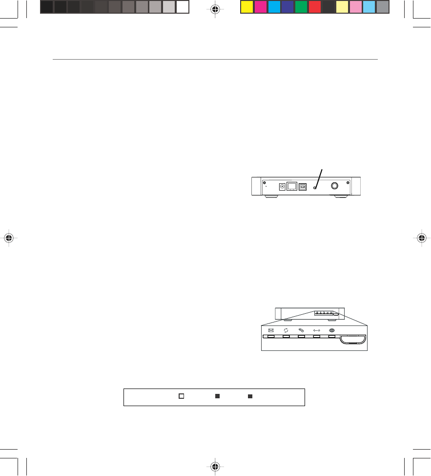
Reset Switch
•Factory Default Reset – Unplug the modem from the AC power. Press and hold the reset
switch while plugging the modem into AC power. Continue holding the switch. Release the
switch when all lights come on (about 6 seconds). This will return the modem to a factory
“out of box” condition. This should only be done if the cable modem has been taken out of
service in one location and is being reconnected to a different service, or if instructed to
do so by your cable company.
Reset switch
3VDC 800mAETHERNETRESET
USB CABLE
The reset switch can be found behind a “toothpick
hole” on the back panel. It performs two functions:
•Basic Reset – Press and release the switch to make
it perform the same function as disconnecting the
power from the modem. It will start up again in
Initialization Mode, see page 24.
Software Download Indicator
Software downloading or update in progress. Lights flash
sequentially from top to bottom.
Legend Off On Flashing
X
16096620 DCW615/25. 02 Connect 6/26/03, 10:45 AM17
18 Chapter 2
Chapter 2: Connections and Setup
Mandatory User Configuration
This feature allows you to configure the gateway to function in your network and gain access to
the Internet through your cable company. Your ISP may require the use of a Host Name and
Domain Name. You will need to get the setup information from your ISP. If you do not have this
information, please contact your ISP before proceeding.
The instructions from your ISP will tell you how to set up your PC for Internet access.
Also, you must disable any Internet log-on software (such as Ivasion Winpoet or Enternet 300)
and any firewall software (such as ZoneAlarm and Watchdog) on all of your PCs.
Fig. 10
1. Open your web browser. (It’s all right if you get an error
message at this point. Continue following these directions).
Enter http://192.168.100.1 in the browser’s Address field if
your gateway is in the CM Mode, or http://192.168.0.1 if it
is in the RG or CH Mode. Press the Enter key.
2. An Enter Network Password window appears (for Windows
XP users, the screen may look different). Leave the User
Name field empty, and enter admin in lowercase letters in
the Password field (admin is the default password). Then,
click the OK button.
3. If you are in CM or CH mode, the Basic webpage group
hyperlink is visible. In this case, select the Basic Setup web
page by using the hyperlinks in the sidebar at the left of the
screen. Otherwise, skip to step 4. Based on the setup
instructions from your cable company, you may need to
enter the following information.
LAN IP Address: The value for the gateway’s local IP address
is shown on the Setup screen. The default value is
192.168.0.1. We recommend you keep this setting.
Host Name and Domain Name: These fields allow you to
provide a host name and domain name for the gateway.
These fields are usually left blank. If requested by your cable
company, complete these two fields.
Fig. 11
16096620 DCW615/25. 02 Connect 6/26/03, 10:45 AM18
Chapter 2 19
Chapter 2: Connections and Setup
Static IP Address and IP Mask: If your cable company says that you are connected through a
static or fixed IP address, you should enter the field of Default Gateway, Primary DNS and/or
Secondary DNS also.
Spoofed MAC Address: You can give a spoofed MAC Address to hide your gateway’s real MAC
address. However, this is NOT recommended, as this could cause an address conflict, causing
your connection to the network to be rejected.
Fig. 12
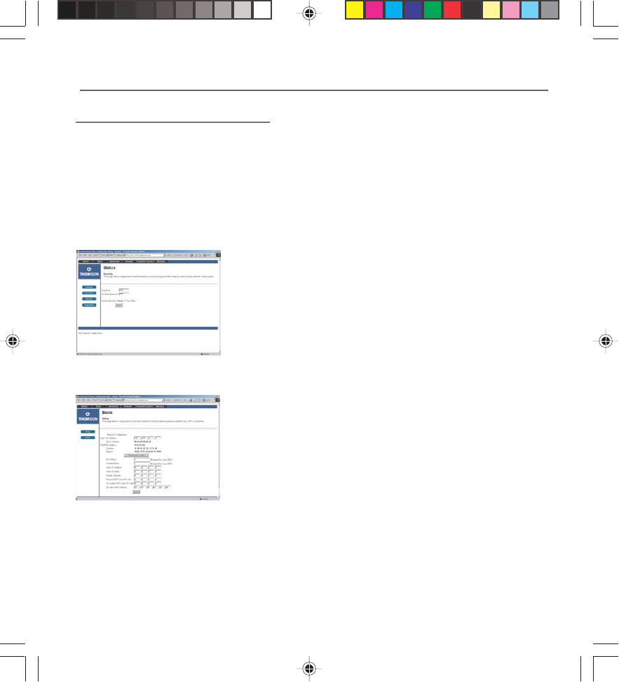
4. The gateway provides a Status Security webpage where you
can change the web page’s access password and restore
factory default of the gateway. Also, you can enable/disable
the DHCP Server function and change the default “admin”
password to the desired password.
IMPORTANT: If you have previously enabled any Internet-
Sharing Proxy server software on any of your PCs, disable it.
Some examples of Internet-sharing software are Internet LanBridge, Wingate, ICS, and Sygate. To
disable your Internet-sharing software:
• If you are running Netscape Navigator: Click Edit >> Preference >> Advanced >> Proxies >,
and click Direct Connection to the Internet.
•If you are running Internet Explorer v5 or better, click Start >> Settings >> Control Panel >>
Internet Options >> Connections >> LAN Settings. Remove the checks from all three boxes.
Click OK to continue.
5. Click the Apply button to save your settings. Close the web browser.
6. Restart your computers so that they can obtain the gateway’s new settings.
Your PC should now be able to access the Internet. The next steps are now:
1. Configure your Gateway such that it is able to support additonal PCs through a wired or
wireless connection.
2. Define the Firewall settings (optional).
16096620 DCW615/25. 02 Connect 6/26/03, 10:45 AM19

Chapter 3: Networking and Advanced Settings
Illustrations contained in this document are for representation only.
20 Chapter 3
Advanced User Configuration
Three Networking Modes
Your gateway can be configured to provide connectivity between your cable company and your
home LAN in any one of three Networking Modes: CM, RG, and CH. This mode setting is under the
control of your cable company, who can select the mode to match the level of home networking
support for which you have subscribed. All units ship from the factory set for the RG mode, but a
configuration file which the cable company sends the cable modem section during its
initialization can change it. This instruction book describes the RG mode as available out of the
factory.
The Wireless Cable Gateway offers local management capability through a built in HTTP server
and a number of diagnostic and configuration web pages. These pages are available from http://
192.168.0.1 in Residential Gateway (RG) and Cable Home (CH) modes, and http://192.168.100.1 in
Cable Modem (CM) mode. Not all pages are available in some modes.
Some information on two of the following web pages MUST BE configured, as explained in
Mandatory User Configuration: Status…Security web page and Basic...Setup web page.
In addition, more configuration and diagnostics are possible through the following additional web
pages, most of which are aimed at controlling the advanced networking functions of the gateway.
To navigate between pages, use the hyperlinks on the sidebar which appear on the left side of all
pages.
Your cable company may not support the reporting of some items of information listed on your
gateway’s internal web pages. In such cases, the information field appears blank. This is normal.
In the CM Mode, the simplest configuration mode of the gateway, or in the CH Mode, where you
have subscribed to an outside service (your cable company or another party) to remotely manage
your home network configuration, you will see only the Status and Wireless web page hyperlinks
in the sidebar, indicating only these page groups are available.
In the RG Mode, the mode where you manage your home network configuration, you will see web
page hyperlinks to all five page groups: Status, Basic, Advanced, Firewall, and Wireless. The
following section explains all of the available pages for all of the modes.
16096620 DCW615/25. 03 Network 6/26/03, 10:45 AM20
Chapter 3: Networking and Advanced Settings
Chapter 3 21
Status Web Page Group
Fig. 13
Fig. 12
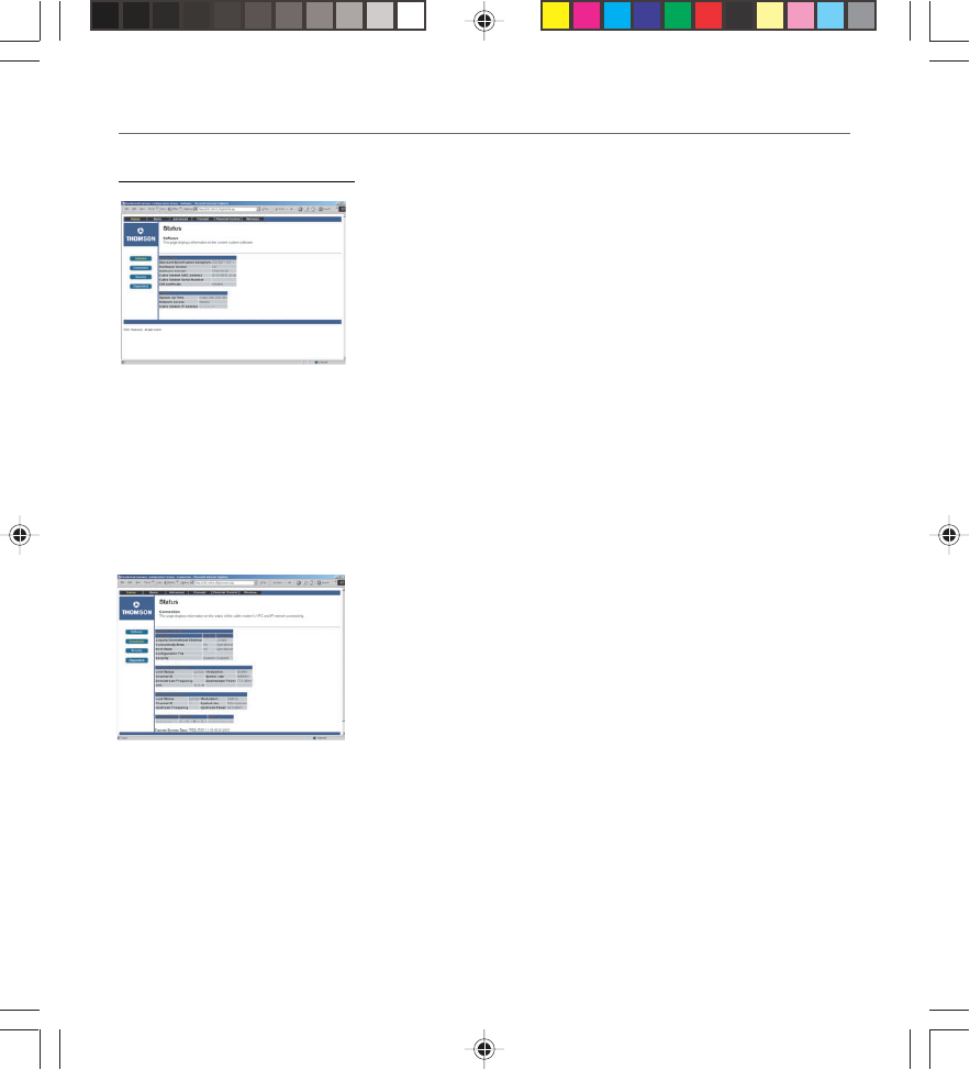
Software Web Page (Fig. 12)
The Information section of this page provides hardware and
software information about your gateway that may be useful to
your cable company. You can view your operating software
version but not change it. This is because your gateway adheres
to the DOCSIS Cable Modem standard, which requires that your
cable company perform any software upgrade of the gateway
from the gateway WAN side.
The Status section of this page shows how long your gateway has
operated since last being powered up, and some key information
the Cable Modem section received during the initialization
process with your cable company. If Network Access shows
“Allowed,” then your cable company has configured your gateway
to have Internet connectivity. If Network Access shows otherwise,
you may not have Internet access, and should contact your cable
company to resolve this.
Connection Web Page (Fig. 13)
This page reports diagnostic information about the initialization
and operating status of your gateway that can be useful at the
time of installation. It can also be useful to your cable company’s
support technician if you’re having problems.
16096620 DCW615/25. 03 Network 6/26/03, 10:45 AM21
Chapter 3: Networking and Advanced Settings
22 Chapter 3
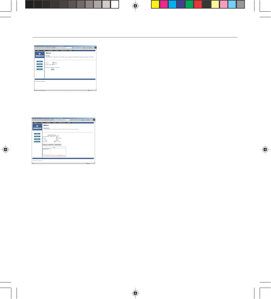
Security Web Page (Fig. 14)
This page is used to set a password that enables you to access
all the internal web pages as explained before under Mandatory
User Configuration. The password can be a maximum of 8
characters and is case sensitive. In addition, this page can be
used to restore the gateway to its original factory settings. Use
this with caution, as all the settings you have made will be lost.
To perform this reset, set Restore Factory Defaults to YES and
click Apply. This has the same affect as a factory reset using the
rear panel reset switch, where you hold in the switch until all
indicators come on, then release.
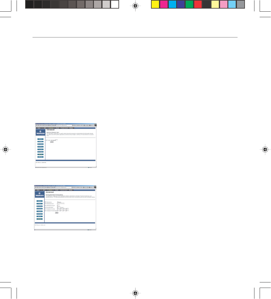
Diagnostics Web Page (Fig. 15)
This page verifies you have IP connectivity from your gateway
to other IP addresses on the WAN or LAN side, such as when
you want to confirm you have successfully configured one of
your PCs for TCP/IP operation.
When you ping an Internet device, you send a packet to its TCP/
IP stack, and it sends one back to yours. Enter the IP address
you want to ping, then click Start Test. Wait a few seconds,
then click your web browser’s refresh button. Success reported
in the Results box means IP connectivity is working from your
CM TCP/IP stack to the target’s stack.
Note: Firewalls may cause pings to fail but still provide you TCP/IP
access to selected devices behind them. Keep this in mind when pinging
a device that may be behind a firewall. Ping is most useful to verify
connectivity with PCs you know have no firewall, such as your own PCs
on your LAN side.
Fig. 15
Fig. 14
16096620 DCW615/25. 03 Network 6/26/03, 10:45 AM22
Chapter 3: Networking and Advanced Settings
Chapter 3 23
Basic Web Page Group
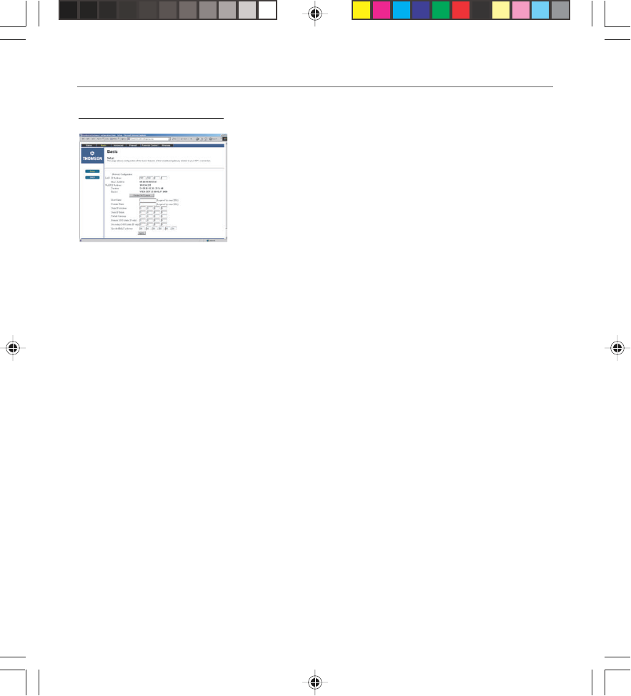
Setup Web Page (Fig. 16)
This page gives you the ability to enter some data your cable
company may require, as explained before in Mandatory User
Configuration. In addition, it enables you to change your
default LAN side IP address from 192.168.0.1, and to view your
WAN side IP address and lease information.
Your gateway can provide NAT/PAT (Network and Port Address
Translation) as an element of security to prevent others from
reaching your PCs when not authorized. To accomplish this, the
gateway watches packets you send from your PC to Internet
sites. Each time you send to a site (destination IP address) and
application at that site (port), it translates your PC’s original IP
and source port to new ones, and adds a row to its Connection
Table maintained internally. (Note the different meaning of
‘connection’ here to describe an IP connection versus a physical
cabling connection). If and when that site/application replies, it
looks up the connection and reverses the IP/port process to
direct the response to your PC.
The Connection Table manages itself, but you can also force
this table to be cleared manually. To do this, click the Renew
NAT Lease button.
You can enter a spoofed MAC address that causes your gateway
networking stack to use that MAC address when
communicating instead of the usual WAN MAC address (CM
label + 2, as explained in Chapter 1). Enter the desired MAC
address and press Apply.
Caution: If you enter a MAC address in use by another party, it
can cause an address conflict on the network that could affect
both you and that party.
Fig. 16
16096620 DCW615/25. 03 Network 6/26/03, 10:45 AM23
Chapter 3: Networking and Advanced Settings
24 Chapter 3
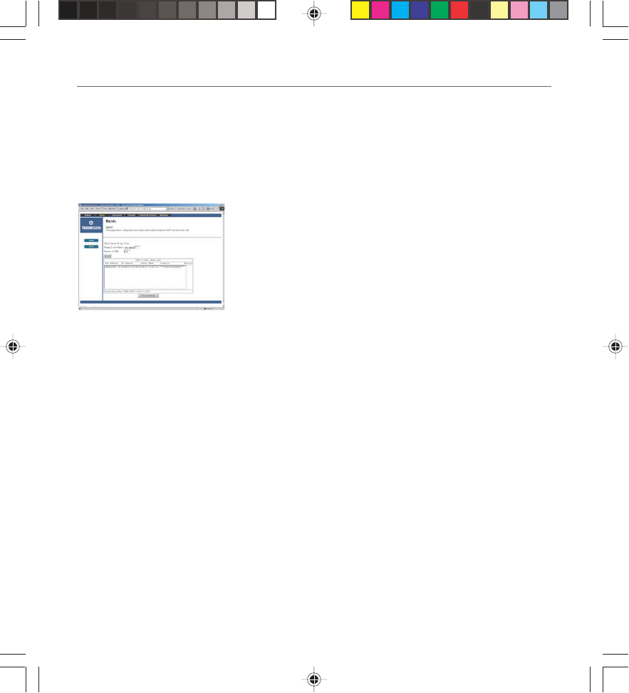
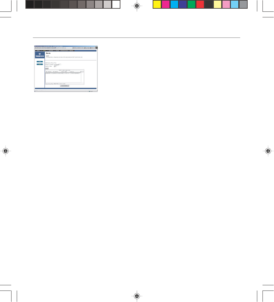
DHCP Web Page (Fig. 17)
This page gives you the ability to activate and deactivate the
DHCP server function of your gateway, and, if the DHCP server
is activated, to see DHCP leases it has provided.
With this function activated, your cable company’s DHCP server
provides one IP address for your gateway, and your gateway’s
DHCP server provides IP addresses, starting at the address you
set in Starting Local Address, to your PCs. A DHCP server leases
an IP address with an expiration time.
To change the lowest IP address that your gateway will issue to
your PCs, enter it into the Starting Local Address box and then
click Apply.
To set the maximum number of PCs to which the gateway will
issue IP addresses, enter it in the Number of CPEs box and then
click Apply. (CPE is another term sometimes used for PC.) The
DHCP Client Lease Info section shows leases the gateway DHCP
server has made, including the IP and MAC addresses of each
PC’s TCP/IP stack. Since MAC addresses are unique and
permanently fixed into hardware, you can identify any PC listed
by its MAC address. The gateway provides leases for 1 hour, and
has an automatic renewal mechanism that will keep extending
a lease as long as the associated PC remains active. If your PC is
set to “obtain an IP address automatically,” it is set to perform
DHCP each time it is rebooted.
You can cancel an IP address lease by selecting it in the DHCP
Client Lease Info list and then clicking the Force Available
button. If you do this, you may have to perform a DHCP Renew
on that PC, so it can obtain a new lease.
Fig. 17
16096620 DCW615/25. 03 Network 6/26/03, 10:45 AM24
Chapter 3: Networking and Advanced Settings
Chapter 3 25
Advanced Web Page Group
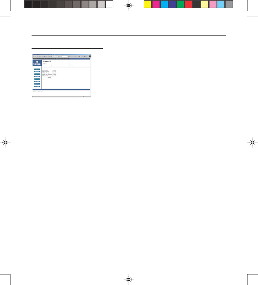
Options Web Page (Fig. 18)
This page allows you to enable/disable some features of the
Wireless Cable Gateway. Check WAN Blocking and then Apply to
prevent others on the WAN side from being able to ping your
gateway. With WAN Blocking on, your gateway will not respond
to pings it receives, effectively “hiding” your gateway.
Check Ipsec Pass Through and then Apply to enable IpSec type
packets to pass WAN <=> LAN. IpSec (IP Security) is a security
mechanism used in Virtual Private Networks (VPNs). E.g., your
employer may offer VPN connectivity to your office network to
provide security.
Click PPTP Pass Through and then Apply to enable PPTP type
packets to pass WAN <=> LAN. PPTP (Point to Point Tunneling
Protocol) is another mechanism sometimes used in VPNs.
Click Remote Config Management and then Apply to make the
configuration web pages in your gateway accessible from the
WAN side. Then you could, for example, access your home
gateway configuration from your workplace, if that location
also had Internet connectivity. Page access is limited to only
those who know the gateway access password you set using the
Status...Security web page.
Click Multicast Enable and then Apply to enable multicast
traffic to pass WAN <=> LAN. You may need to enable this to
see some types of broadcast streaming and content on the
Internet, such as webcasting of a popular live event.
Fig. 18
16096620 DCW615/25. 03 Network 6/26/03, 10:45 AM25
Chapter 3: Networking and Advanced Settings
26 Chapter 3
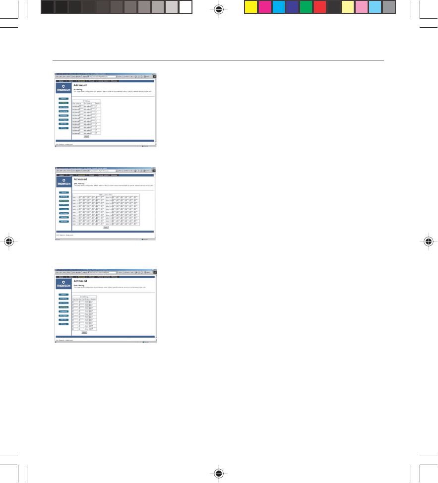
IP Filtering Web Page (Fig. 19)
This page enables you to enter the IP address ranges of PCs on
your LAN that you don’t want to have outbound access to the
WAN. These PCs can still communicate with each other on your
LAN, but packets they originate to WAN addresses are blocked
by the gateway.
Fig. 20
Fig. 19
MAC Filtering Web Page (Fig. 20)
This page enables you to enter the MAC address of specific
PCs on your LAN that you wish to NOT have outbound access
to the WAN. As with IP filtering, these PCs can still
communicate with each other through the gateway, but
packets they send to WAN addresses are blocked.
Port Filtering Web Page (Fig. 21)
This page enables you to enter ranges of destination ports
(applications) that you don’t want your LAN PCs to send packets
to. Any packets your LAN PCs send to these desination ports will
be blocked. For example, you could block access to worldwide
web browsing (HTTP = port 80) but still allow email service
(SMTP port 25 and POP-3 port 110). To enable filtering, set
Start Port and End Port for each range, and click Apply. To block
only one port, set both Start and End ports the same.
Fig. 21
16096620 DCW615/25. 03 Network 6/26/03, 10:45 AM26
Chapter 3: Networking and Advanced Settings
Chapter 3 27
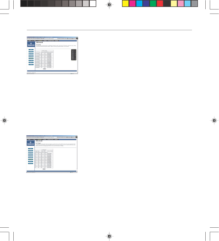
Forwarding Web Page (Fig. 22)
For LAN <=> WAN communications, the gateway normally only
allows you to originate an IP connection with a PC on the
WAN; it will ignore attempts of the WAN PC to originate a
connection onto your PC. This protects you from malicious
attacks from outsiders. However, sometimes you may wish for
anyone outside to be able to originate a connection to a
particular PC on your LAN if the destination port (application)
matches one you specify.
This page allows you to specify up to 10 such rules. For
example, to specify that outsiders should have access to an FTP
server you have running at 192.168.0.5, create a rule with that
address and Start Port = 20 and End Port = 21 (FTP port ranges)
and Protocol = TCP (FTP runs over TCP vs the other transport
protocol, UDP), and click Apply. This will cause inbound packets
that match to be forwarded to that PC rather than blocked. As
these connections are not tracked, no entry is made for them in
the Connection Table. The same IP address can be entered
multiple times with different ports.
Port Triggers Web Page (Fig. 23)
Some Internet activities, such as interactive gaming, require
that a PC on the WAN side of your gateway be able to originate
connections during the game with your game playing PC on the
LAN side. You could use the Advanced...Forwarding page to
construct a forwarding rule during the game, and then remove
it afterwards (to restore full protection to your LAN PC) to
facilitate this. Port Triggering is an elegant mechanism that
does this work for you, each time you play the game.
Port Triggering works as follows. Imagine you want to play a
particular game with PCs somewhere on the Internet. You make
a one time effort to set up a Port Trigger for that game, by
entering into Trigger Range the range of destination ports your
game will be sending to, and entering into Target Range the
Fig. 22
Fig. 23
16096620 DCW615/25. 03 Network 6/26/03, 10:45 AM27
Chapter 3: Networking and Advanced Settings
28 Chapter 3
range of destination ports the other player (on the WAN side) will be sending to (ports your PC’s
game receives on). Application programs like games publish this information in user manuals.
Later, each time you play the game, the gateway automatically creates the forwarding rule
necessary (see Advanced...Forwarding discussion above). This rule is valid until 10 minutes after it
sees game activity stop. After 10 minutes, the rule becomes inactive until the next matched
outgoing traffic arrives.
For example, suppose you specify Trigger Range from 6660 to 6670 and Target Range from 113 to
113. An outbound packet arrives at the gateway with your game-playing PC source IP address
192.168.0.10, destination port 6666 over TCP/IP. This destination port is within the Trigger Range,
so the gateway automatically creates a forwarding rule to forward any inbound packets destined
for port 113 to your game-playing PC at 192.168.0.10.
You can specify up to 10 port ranges on which to trigger.
DMZ Host Web Page (Fig. 24)
Use this page to designate one PC on your LAN that should be
left accessible to all PCs from the WAN side, for all ports. For
example, if you put an HTTP server on this machine, anyone will
be able to access that HTTP server by using your gateway IP
address as the destination. A setting of “0” indicates NO DMZ
PC. “Host” is another Internet term for a PC connected to the
Internet.
Fig. 24
Fig. 25
Routing Information Protocol Setup (Fig. 25)
These very advanced Setups are usually not useful for a
residential application unless a cable operator communicates
the required settings.
16096620 DCW615/25. 03 Network 6/26/03, 10:45 AM28
Chapter 3: Networking and Advanced Settings
Chapter 3 29
Firewall Web Pages Group
Fig. 26
Fig. 27
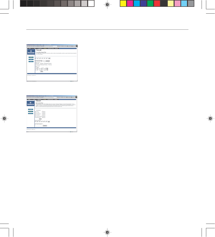
Time of Day (Fig 26)
The Firewall ToD filter page allows you to control the internet
access time period for a specific PC. This is a very useful
Parental Control Feature on top of Content Filtering and
Domain Blocking. It allows you to restrict the Internet access of
some PCs to a limited period of time.
Remark: the PCs MAC address is used to prevent someone from
bypassing the restriction by just changing an IP address or host
name.
Web Filter Web Page (Fig. 27)
This page allows you to enable, disable, and configure a variety
of firewall features associated with web browsing, which uses
the HTTP protocol and transports HTML web pages. On this
page, you designate the gateway packet types you want to have
forwarded or blocked. You can activate settings by checking
them and clicking Apply. Here are some of your choices:
•Activate Keyword Blocking and specify some keywords in
the Keyword List to cause blocking of web pages on the
WAN side with the specified keyword in the content.
•Activate Domain Blocking and specify some Domain Names
(e.g. disney.com) in the Domain List. If you select Deny
Domains, the gateway blocks the listed domains. If you
select Allow Domains, then access to the listed domains is
allowed. If you select Always Block, your choices are always
blocked. If you specify a time frame and weekday range,
then your choices are only blocked during those date/time
frames.
Other types of web-related filtering features can be activated
from this page, including Filter Proxy, Filter Cookies, Filter Java
Applets, Filter ActiveX, Filter Popup Windows, and Firewall
Protection.
16096620 DCW615/25. 03 Network 6/26/03, 10:45 AM29
Chapter 3: Networking and Advanced Settings
30 Chapter 3
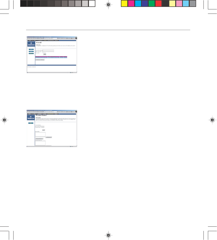
Event Log Web Page (Fig. 28)
The gateway builds a log of firewall blocking actions that the
Firewall has taken. Using this page lets you specify an email
address to which you want the gateway to email this log. You
must also tell the gateway your outgoing (i.e. SMTP) email
server’s name, so it can direct the email to it. Enable Email
Alerts has the gateway forward email notices when Firewall
protection events occur. Click E-mail Log to immediately send
the email log. Click Clear Log to clear the table of entries for a
fresh start.
The log of these events is also visible on the screen. For each
blocking event type that has taken place since the table was
last cleared, the table shows Description, Count, Last
Occurrence, Target, and Source.
Parental Control Web Pages Group (Fig. 29)
This Web page allows to block web pages based on keywords
content or Domain name. By enabling the keyword blocking
and adding words to the list, any web page contining one of
these words will be blocked.
Similarly, any domain listed with the “Domain Blocking”
activated will be rejected. A domain is a group of computers.
For example, to block access to Yahoo and any computers
related to its network, you would enter yahoo.com. Entering a
domain name is easier than entering the IP addresses or
individual host names to block.
Fig. 28
Fig. 29
16096620 DCW615/25. 03 Network 6/26/03, 10:45 AM30
Chapter 3: Networking and Advanced Settings
Chapter 3 31
Wireless Web Pages Group
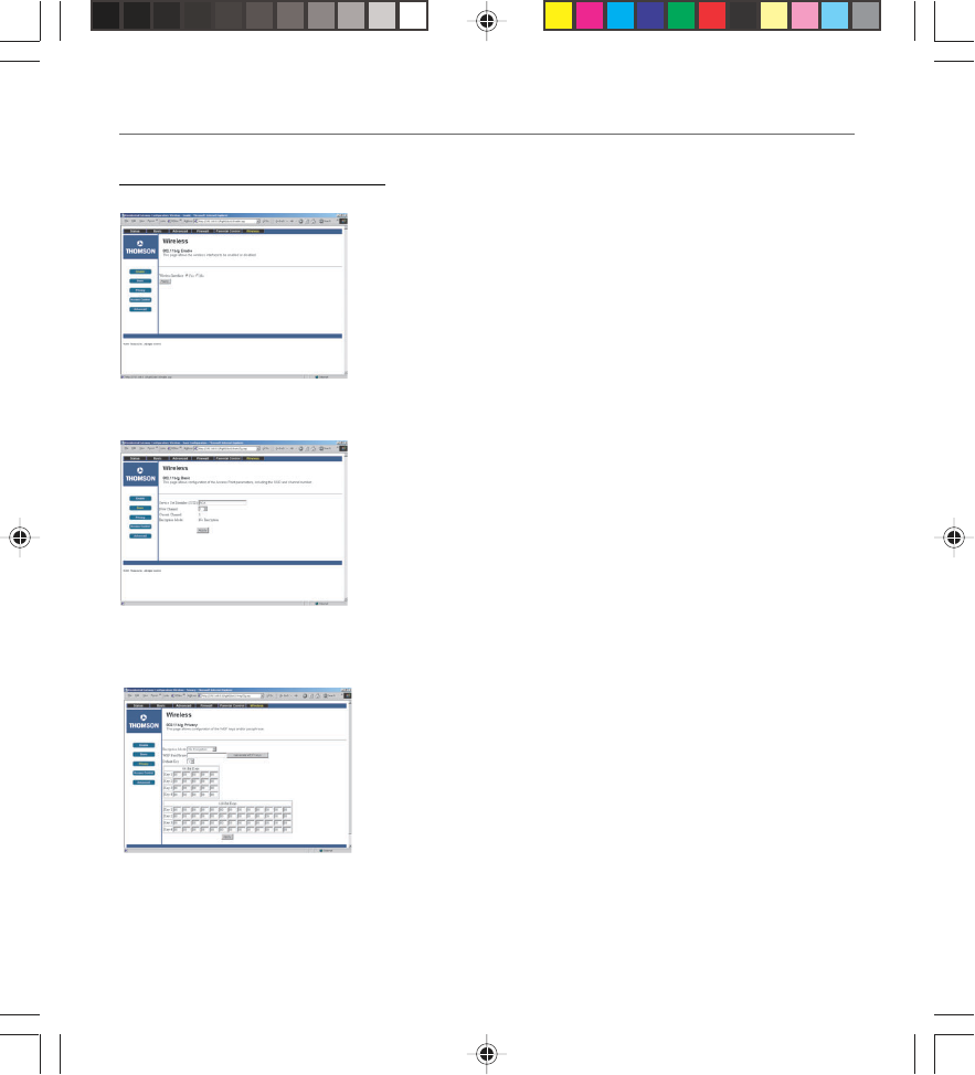
Enable Web Page (Fig. 30)
Use this page to enable or disable the wireless functionality. If
you enable it for the first time, proceed then to the “Basic” Web
Page to configure the wireless settiings.
Fig. 30
Fig. 31
Basic Web Page (Fig. 31)
Use this page to configure the wireless channel you want to use
and the name you will assign to your network (SSID). These
must match the settings you make on your wireless-equipped
PC you want to be a part of your local area network (LAN).
Once you have done your modifications, click on “Apply” to
validate them. At that stage, you should be able to perform the
first wireless connection with a wireless equipped PC. You can
then move to the next step which is to secure the wireless
connection by going to the Privacy Web page.
Privacy Web Page (Fig. 32)
The Privacy feature in the wireless section encrypts, i.e.
effectively “scrambles,” all radio communication between your
gateway and remote wireless-connected PCs. This provides
Wired-Equivalent Privacy (WEP) on your wireless LAN. Use this
page to activate encryption if desired, and set the type to use,
as well as the encryption keys.
The longer the encryption key, the more difficult it is to
decypher it for a “hacker.” In order to generate the keys,
composed of aphanumeric numbers, select a key number and
Fig. 32
16096620 DCW615/25. 03 Network 6/26/03, 10:45 AM31
Chapter 3: Networking and Advanced Settings
32 Chapter 3
type a word or sentence and click on “generate WEP keys.” The gateway will automatically
generate a key randomly. You have to write it down and use the same on the wireless equipped
PC to allow proper descrambling.
Fig. 33
Fig. 34
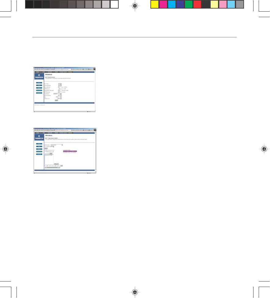
Advanced Web Page (Fig. 33)
This page enables some advanced 802.11b settings to be made.
The factory default values should provide good results in most
cases. We don’t recommend you change these settings unless
you have technical knowledge of 802.11 wireless technology.
Access Control Page (Fig. 34)
The Access Control feature enables you to restrict wireless access
to specific computers. Use this feature to prevent outsider
wireless PCs from connecting to your private network. The
Access Control Web Page allows you to reinforce the security of
the wireless connnection by:
•Hiding the network Name to other PCs with the “Close
Network” functionality activated (no SSID Broadcast
(Network Name).
•Open System, Shared Key, Open System or Shared Key
802.11 networks use two authentication methods: open-
system authentication and shared-key authentication. In
both schemes, each mobile client (called a station) must
authenticate to the access point.
•Open-system authentication might better be called “no
authentication”, because no actual authentication takes
place: the station says “please authenticate me”, and the
Access Point does so, with no credential exchange.
•Shared-key authentication is somewhat more robust (except
that it depends on WEP). The station requests
16096620 DCW615/25. 03 Network 6/26/03, 10:45 AM32

Chapter 3: Networking and Advanced Settings
Chapter 3 33
authentication, and the access point (AP) responds with a WEP-encrypted challenge. The
station can decrypt the challenge and respond only if it has the correct WEP password.
When both “Open system and Shared key” options are selected, the authentication will be
done according to the mobile client station) request : with or without encryption?? In both
of these methods, the station must also know the service set identifier (SSID) of the Access
Point.
Your Gateway identifies wireless PCs by their WiFi MAC Address. This address consists of a
string of 6 pairs of numbers 0 – 9 and letters A - F, such as 00 90 4B F0 FF 50. It is usually
printed on the WiFi card of the device (e.g. the PCMCIA card in a laptop). It can also be
determined from a Windows DOS prompt as explained below.
The Connected Clients list on the Access Control Web Page always shows PCs that currently
have wireless connections to your Gateway. Your Gateway default access control configura-
tion (“Allow everyone access”) allows access within reception range by any computer that
has your same privacy (key) settings. You might want to restrict the list of PCs having access
to the network (e.g. excluding neighbors or PCs used locally only). The process is described
below.
To restrict access to only specific computers:
1. Select “Restrict access to List.”
2. Enter the WiFi MAC address of a PC you wish to have access.
3. Click on the “Add” button.
4. Repeat steps 2 and 3 for the other PCs you wish to have access.
5. Click on “Submit Access List Changes” to make the changes effective.
To remove access privileges for a listed computer:
1. Select the MAC address in the list.
2. Click on “Remove.”
3. Click on “Submit Access List Changes” to make the changes effective.
16096620 DCW615/25. 03 Network 6/26/03, 10:45 AM33
Chapter 3: Networking and Advanced Settings
34 Chapter 3
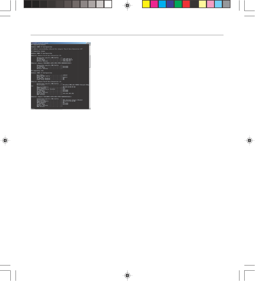
Determining WiFi MAC Address (Fig. 35)
If a printed WiFi MAC address for a PC cannot be found, it
can be determined as follows from the MS-DOS prompt in
the MS Windows running on that computer:
1. Start MS-DOS. In Windows 98, this is “Start” ... “Run” ,,,
[type in] “command” ... “OK”. In Windows Me, 2k and XP, this
is “Start” ... “Run” ... [type in] “cmd” ... OK.
2. List your installed interfaces, by typing “ipconfig /all” and
pressing “Enter.”
3. Find the MAC address associated with the interface
description that matches your wireless card description. In
this example, the phrase “802.11b PCMCIA” clearly identifies
the WiFi card among the listed interfaces.
Fig. 35
16096620 DCW615/25. 03 Network 6/26/03, 10:45 AM34

Chapter 4: Additional Information
Chapter 4 35
Illustrations contained in this document are for representation only.
Troubleshooting
You can correct most problems you have with your product by consulting the troubleshooting list
that follows. If you need service, please contact your service provider.
Unit won’t turn on
•Make sure the unit is plugged in.
•Check the wall receptacle (or extension cord) to make sure it is “live” by plugging in
something else.
Gateway appears to be locked up
•Press and hold the Reset button on the back of the unit for 5 seconds. The unit reboots.
No connection after more than 5 minutes
•Make sure all connections are secure and try connecting to your service provider again. If you
still have problems connecting to the network, contact your service provider.
16096620 DCW615/25. 04 Addit 6/26/03, 10:45 AM35
Chapter 4: Additional Information
36 Chapter 4
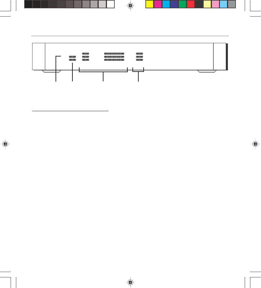
Front of the Unit (DCW615)
1. Power Indicates when the unit is on.
2. Test Indicates when the unit goes through its self-diagnosis mode during boot-up and
restart. It turns off upon successful completion of the startup sequence.
3. The LAN indicators
USB Indicates when the USB port is properly connected to your PC and active.
HPNA Indicates when the HPNA port is plugged in and ready to transfer data.
WLAN Indicates when the Wireless PC card is present.
Link/Act Indicates steady on when link is established and blinks when data is flowing
through the corresponding LAN port.
Full/Col Indicates steady at full duplex mode, off at half duplex mode, and blinks when
collisions are detected on the corresponding LAN port.
100/10 Indicates steady on when a successful 100Mbps connection is made through the
corresponding LAN port.
4. The WAN indicators
Cable-Link Indicates steady on when cable system initialization is complete and ready to
transfer data. Blinks when scanning for a downstream DOCSIS RF carrier.
Receive Blinks when user data is going through the cable modem to the PC.
Send Blinks when user data is going through the cable modem from the PC.
HPNA
WLAN
Power
Tes t
USB
Full/Col
100/10
Link/Act
Receive
Send
Cable-Link
Link/Act Cable
1 2 3 4
Ethernet
2
1
3
4
5
12 34
16096620 DCW615/25. 04 Addit 6/26/03, 10:45 AM36
Chapter 4: Additional Information
Chapter 4 37
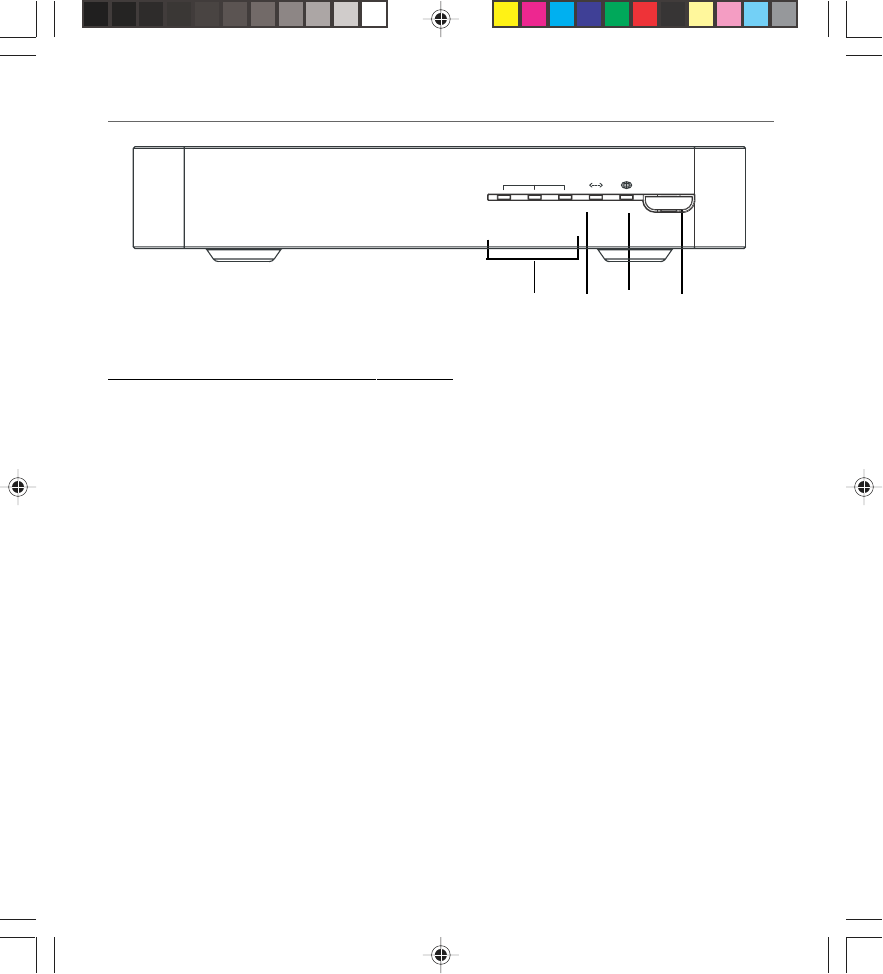
Front of the Unit (DCW625/TCW690)
1. The PC Link indicators
WLAN Indicates when the Wireless PC card is present.
PC Link Indicates steady on when link is established and blinks when data is flowing
through the corresponding LAN port.
USB Indicates when the USB port is properly connected to your PC and active.
2. Cable-Link indicator Indicates steady on when cable system initialization is complete and
ready to transfer data. Blinks when scanning for a downstream DOCSIS RF carrier.
3. Internet indicator Indicates when unit is on.
4. Internet On/Off Turns the unit on and off.
123 4
Internet On/Off
USB
WLAN
PC Link
CableLink Internet
16096620 DCW615/25. 04 Addit 6/26/03, 10:45 AM37
Chapter 4: Additional Information
38 Chapter 4
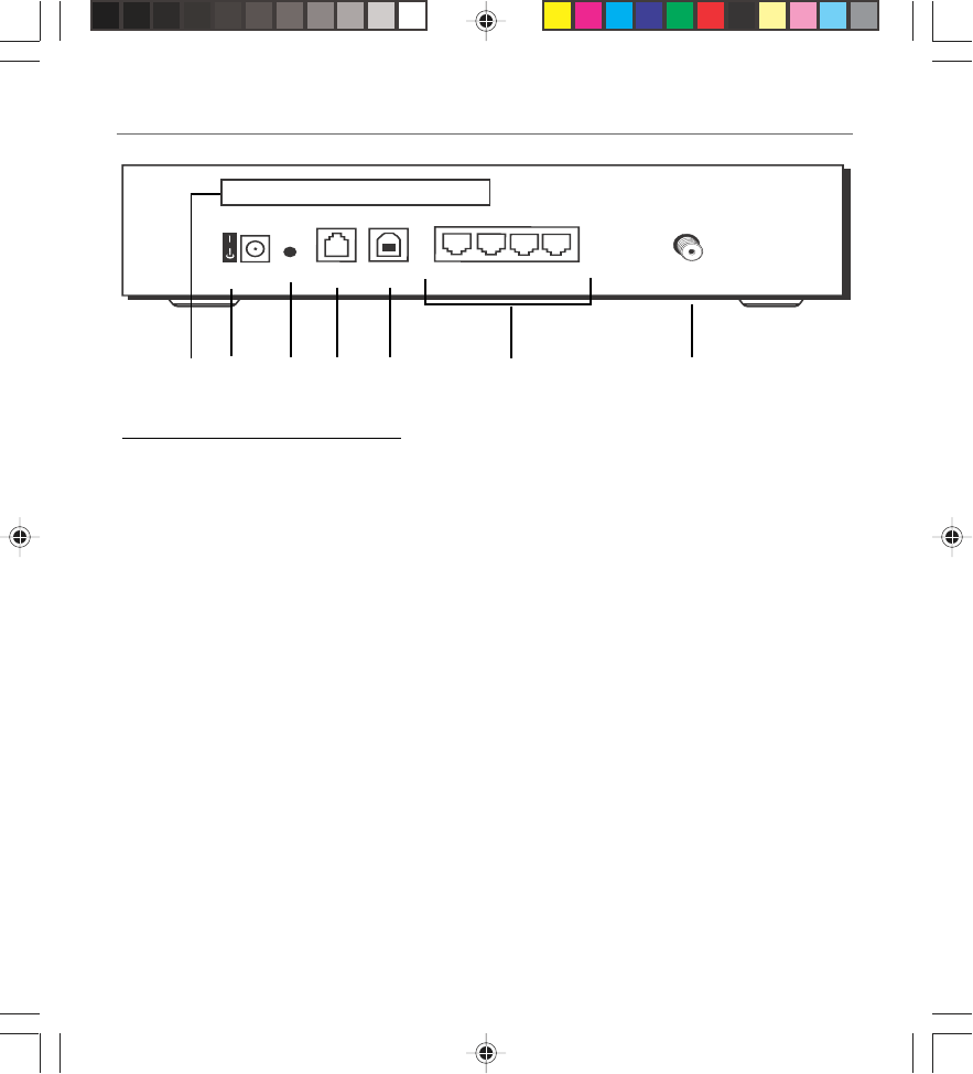
Back of the Unit (DCW615)
Description of Jacks (from left to right)
1. Wireless PC card Connects to the Wireless Network PC Card to enable wireless
features. This is not hot swappable.
2. Power switch and jack Connects to the AC power adapter.
3. Reset button Resets the gateway’s TCP/IP connections.
Pressing the Reset button and holding it in for a few seconds will
clear all of the gateway’s data and restore the factory defaults. This
should be done only after you have exhausted all troubleshooting
options. By resetting the gateway, you clear all configurations you
have set using the gateway web pages, and run the risk of creating
conflicts between your PC’s actual IP Addresses and the factory
default addresses embedded into the gateway.
4. HPNA Connects to the telephone wiring in your house.
5. USB Connects to the USB jack on your PC.
6. Ethernet ports Connect to networked devices, such as PCs, print servers and any
other Ethernet devices you want to put on your network.
7. CABLE Connects to the coaxial cable jack from your cable company.
Power HPNA
Reset USB 1 2 3 4
CABLE
Wireless PC Card
1234 56 7
16096620 DCW615/25. 04 Addit 6/26/03, 10:45 AM38
Chapter 4: Additional Information
Chapter 4 39
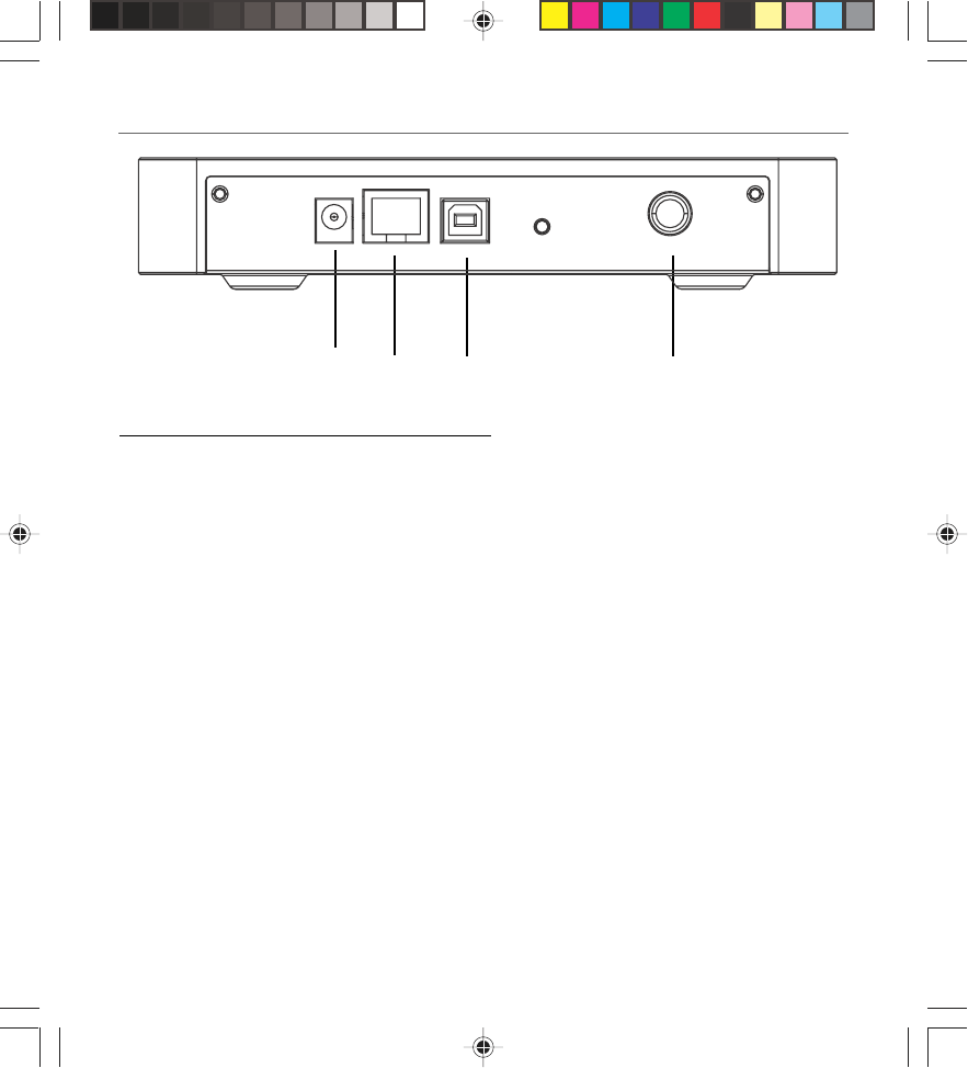
Back of the Unit (DCW625/TCW690)
Description of Jacks (from left to right)
1. Power switch and jack Connects to the AC power adapter.
2. HPNA Connects to the telephone wiring in your house.
3. USB Connects to the USB jack on your PC.
4. CABLE Connects to the coaxial cable jack from your cable company.
1234
16096620 DCW615/25. 04 Addit 6/26/03, 10:45 AM39

Chapter 4: Additional Information
40 Chapter 4
Detailed Explanation of Jacks
The Wireless Cable Gateway provides the following data connections:
WAN Side:
Cable TV connection- connects to your cable service
LAN Side:
Ethernet RJ-45 jacks — connect up to four 10 or 100 Mbps Ethernet cables to PCs or to Ethernet
switches to connect more PCs. Each PC must be equipped with an Ethernet network interface, and
must have the TCP/IP protocol configured to operate over that interface.
USB- connects one USB cable to your PC. The PC must be equipped with a USB network interface.
In addition, the USB driver on the DCW615 CD-ROM must be installed on the connected PC, and
the PC must have the TCP/IP protocol configured to operate over that USB interface.
HPNA- connects one telephone cable from the gateway to your nearest telephone outlet, utilizing
your home telephone wiring to extend your LAN to other rooms of your home. Then connect up
to 254 PCs via telephone cables and HPNA adapters, to other telephone outlets in your home.
Each PC must be equipped with an HPNA network interface (adapter), and must have the TCP/IP
protocol configured to operate over that interface.
Wireless Card- utilizes the 2.4 GHz wireless 2-way technology built into the DCW615 to reach up
to 254 PCs in your home. Each PC must be equipped with an 802.11b Wireless Interface, and must
have the TCP/IP protocol configured to operate over that interface.
16096620 DCW615/25. 04 Addit 6/26/03, 10:45 AM40

Chapter 4: Additional Information
Chapter 4 41
Care and Cleaning
CAUTION: Unplug your unit before cleaning.
You can clean the unit as required, using a soft lint-free cloth. Be sure to occasionally dust the
ventilation slots in the cabinet to help assure adequate ventilation.
Never use strong cleaning agents, such as ammonia-based cleaners, or abrasive powder. These
types of cleaners will damage the unit.
Avoid placing drinks or vases with water on top of the unit. This could increase the risk of fire or
shock hazard or damage to the unit.
Service Information
If you purchased or leased your Wireless Cable Gateway directly from your service provider, then
warranty service for the unit may be provided through your service provider or its authorized
representative. For information on 1) Ordering Service, 2) Obtaining Customer Support, or 3)
Additional Service Information, please contact your service provider.
16096620 DCW615/25. 04 Addit 6/26/03, 10:45 AM41

Chapter 4: Additional Information
42 Chapter 4
FCC Declaration of Conformity and Industry Canada Information
This device complies with Part 15 of the FCC Rules. Operation is subject to the following two
conditions: (1) this device may not cause harmful interference, and (2) this device must accept
any interference received, including interference that may cause undesired operation.
Trade Name: RCA Model: DCW615, DCW625
Thomson Model: TCW690
Equipment Classification: Computing Device Accessory
Responsible Party: Thomson Inc.
10330 N. Meridian Street
Indianapolis, IN 46290
Telephone 580-634-0151
This equipment has been tested and found to comply with the limits for a Class B digital device,
pursuant to Part 15 of the FCC Rules. These limits are designed to provide reasonable protection
against harmful interference in a residential installation. This equipment generates, uses, and can
radiate radio frequency energy and, if not installed and used in accordance with the instructions,
may cause harmful interference to radio communications. However there is no guarantee that
interference will not occur in a particular installation. If this equipment does cause harmful
interference to radio or television reception, which can be determined by turning the equipment
off and on, the user is encouraged to try and correct the interference by one or more of the
following measures:
•Reorient or relocate the receiving antenna.
•Increase the separation between the equipment and receiver.
•Connect this equipment into an outlet on a circuit different from that to which the receiver is
connected.
•Consult your service provider or an experienced radio/TV technician for help.
FCC regulations state that unauthorized changes or modifications to this equipment may void the
user’s authority to operate it.
16096620 DCW615/25. 04 Addit 6/26/03, 10:45 AM42

Chapter 4: Additional Information
Chapter 4 43
This Class B digital apparatus meets all requirements of the Canadian Interference Causing
Equipment Regulations.
Additional FCC Information
This equipment complies with Part 68 of the FCC rules and the requirements adopted by the
ACTA. On the back or bottom side of this equipment is a label that contains, among other
information, a product identifier in the format US:AAAEQ##TXXXX. If requested, this number
must be provided to the telephone company.
A plug and jack used to connect this equipment to the premises wiring and telephone network
must comply with the applicable FCC part 68 rules and requirements adopted by the ACTA. A
compliant telephone cord and modular RJ11 plug is provided with this product. It is designed to
be connected to a compatible modular jack that is also compliant. See installation instructions
for details.
The Ringer Equivalence Number (REN) is used to determine the number of devices that may be
connected to a telephone line. Excessive RENs on a telephone line may result in the devices not
ringing in response to an incoming call. In most but not all areas, the sum of the RENs should not
exceed five (5.0). To be certain of the number of devices that may be connected to a line, as
determined by the total RENs, contact the local telephone company. The REN number is located
on the label of this product.
If this equipment causes harm to the telephone network, the telephone company will notify you
in advance that temporary discontinuance of service may be required. But if advance notice isn’t
practical, the telephone company will notify the customer as soon as possible. Also, you will be
advised of your right to file a compliant with the FCC if you believe it is necessary.
The telephone company may make changes in its facilities, equipment, operations or procedures
that could affect the operation of the equipment. If this happens the telephone company will
provide advance notice in order for you to make necessary modifications to maintain
uninterrupted service.
If trouble is experienced with this equipment, for repair or warranty information please refer to
the appropriate section of this manual. This product is not user serviceable. If the equipment is
causing harm to the telephone network, the telephone company may request that you disconnect
the equipment until the problem is resolved.
16096620 DCW615/25. 04 Addit 6/26/03, 10:45 AM43

Chapter 4: Additional Information
44 Chapter 4
Connection to party line service is subject to state tariffs and may not be allowed. Contact the
state public utility commission, public service commission or corporation commission for
information.
If your home has specially wired alarm equipment connected to the telephone line, ensure that
the installation of this Wireless Cable Gateway does not disable alarm equipment. You may need
to consult your Telephone Company or qualified installer.
This product meets the applicable Industry Canada technical specifications. The term “IC” before
the certification / registration bumber only signifies that the Industry Canada technical
specifications were met.
The Ringer Equivalence Number is an indication of the maximum number of devices allowed to
connect to a telephone interface. The termination on an interface may consist of any
combination of devices subject only to the requirement that the sum of the RENs of all the
devices does not exceed five.
16096620 DCW615/25. 04 Addit 6/26/03, 10:45 AM44

Chapter 4: Additional Information
Chapter 4 45
Product Specifications
WAN Cable Interface F type female 75 ohm
LAN 4 10/100 BASE-T 1 USB, 1.1 Connector Type B, 1 HomePNA2.0 RJ-11, 1
IEEE 802.11b (2.4 GHz Unlicensed ISM radio band)
System Power 12V/700mA
Power Supply 12V/1.25A
EMI/EMC FCC Class B, CE Class B, VCCI Class B.
Operation Requirement Operating Temp. 0ºC to 40ºC (32ºF to 104ºF) Storage Temp. -20ºC to
70ºC (-4ºF to 158ºF) Operating
Humidity 10% to 85% Non-Condensing Storage Humidity 5% to 90% Non-
Condensing
Dimensions 186 x 155 x 63 (mm)
Main features:
Cable Modem Connection
•DOCSIS 1.0 and 1.1 RFI compliant
•64/256QAM auto detection downstream
•QPSK/16QAM upstream
•Fragmentation and concatenation enabling Quality of Service (QoS) features
•IP and LLC filtering
HomePNA Interface
•Integrated 32 Mbps HomePNA 2.0
• HomePNA 2.0 allows you to share your cable access using existing home telephone wiring
USB Interface
•USB 1.1 compliant full speed (12 Mbps) device interface for Windows 98SE, Windows 2000,
Windows Me, or Windows XP
16096620 DCW615/25. 04 Addit 6/26/03, 10:45 AM45

Chapter 4: Additional Information
46 Chapter 4
Wireless Interface
•11 Mbps IEEE 802.11b Wireless LAN
•Frequency band: 2400-2497 MHz
•Supports 64/128 bit RC4 authentication and encryption
•Fallback rates of 5.5, 2, and 1Mbps
•Communicates with all Wi-Fi certified wireless adapters
Networking
•IEEE 802.1d compliant bridging
•DHCP Client
•DHCP Server
•DNS Relay
•ARP
•ICMP
•FTP/TFTP
•Telnet
Security and Firewall
•Password protected configuration via web browser
•IP filtering; allows you to configure IP address filters
•MAC filtering; allows you to configure MAC address filters
•Port filtering; allows you to configure TCP/UDP port filters
•URL content filtering
•URL filtering blocks Proxy, Cookies, Java and ActiveX
•Traffic and Security Event log
•PAP and CHAP authentication with PPP
•Stateful Packet Inspection to protect against both Denial of Service and Distributed Denial of
16096620 DCW615/25. 04 Addit 6/26/03, 10:45 AM46

Chapter 4: Additional Information
Chapter 4 47
Service attacks, including:
•Reassembly attacks
•SYN Attack (SYN Flood)
•ICMP Flood
•Ping of Death Attack
•Tear Drop Attack
•IP Spoofing Attack
•LAND Attack
•Jolt
•Winnuke Attack (Netbios out-of-bound)
•OverDrop
•BONK, BOINK
•Blind Spoofing
•Echo/Chargen
•Storm
•Smurf Attack
•Mime Flood
•De-Militarized Zone (DMZ) support, allowing a LAN side computer to expose all non-filtered
ports to the WAN
•URL keyword blocking for web access control
NAT
•With popular ALG support
•With port triggers
•With port forwarding, including support for:
16096620 DCW615/25. 04 Addit 6/26/03, 10:45 AM47

Chapter 4: Additional Information
48 Chapter 4
• FTP
• IRC
• H.323
• Quake
• Blizzard games
• Chat ALG
• Real Audio/Video
• CUSEEME
• Netmeeting
• MS Games (excluding game zone)
• DIABOLO II
• Activision Games
• PCAnywhere
• SSL
• NNTP
Virtual Private Network (VPN) Feature
•PPTP and IPSec pass-through can be enabled/disabled
16096620 DCW615/25. 04 Addit 6/26/03, 10:45 AM48

16096620 DCW615/25. 04 Addit 6/26/03, 10:45 AM49

Thomson Inc.
10330 North Meridian Street
Indianapolis, IN 46290
© 2003 Thomson Inc.
Trademark(s) Registered
Marca(s) Registrada(s)
Printed in Taiwan
TOCOM 16286570
THOMSON
Please do not send any products to the Indianapolis address listed in this manual or
on the carton. This will only add delays in service for your product.
Visit the RCA web site at www.rca.com
16096620 DCW615/25. 04 Addit 6/26/03, 10:45 AM50