ASUSTeK Computer DPC2434 WIRELESS CABLE MODEM User Manual DPC2434 UserMan
ASUSTeK Computer Inc WIRELESS CABLE MODEM DPC2434 UserMan
UserManual.wiki
>
ASUSTeK Computer
>
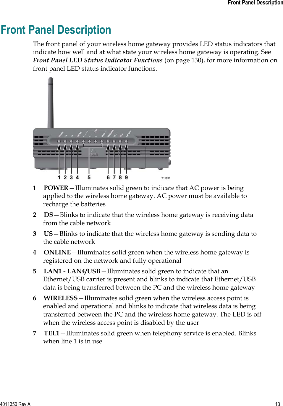
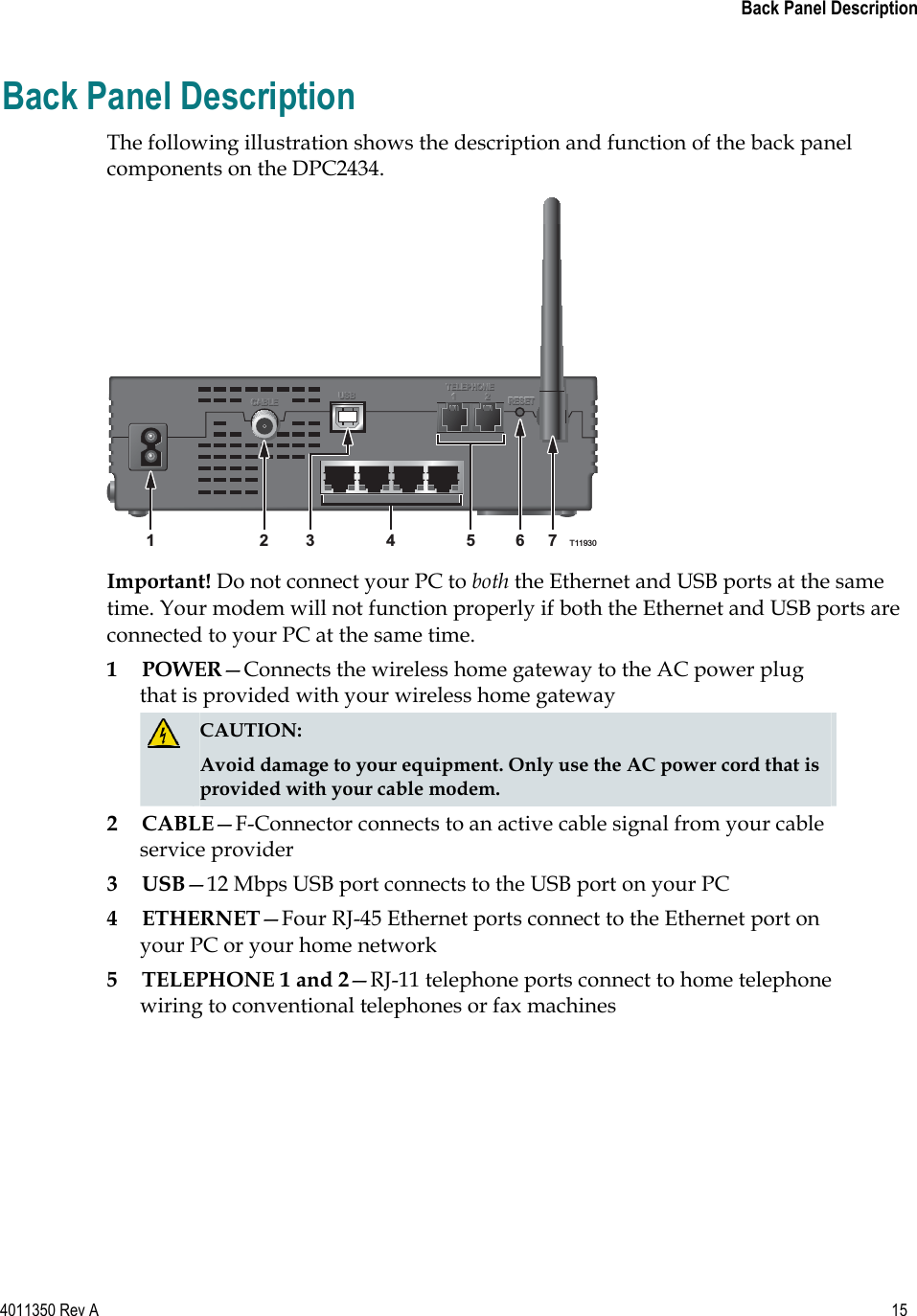
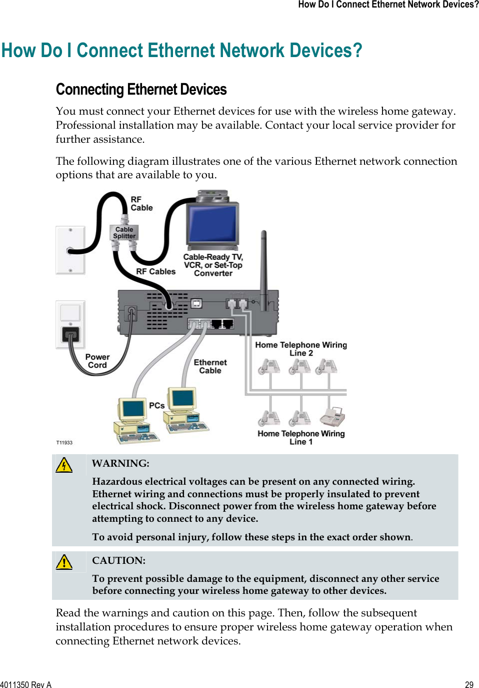
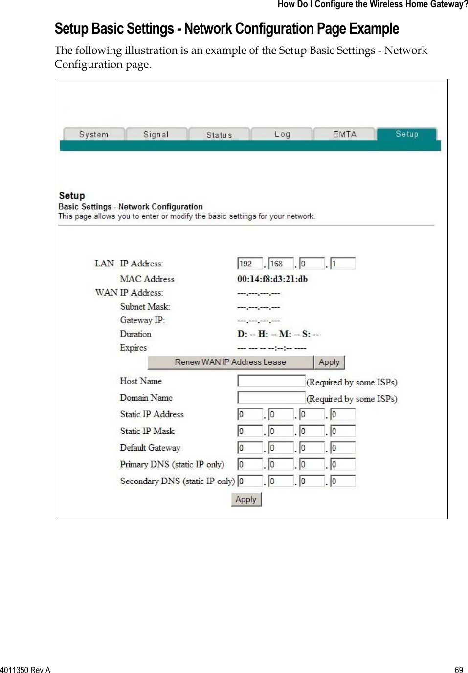
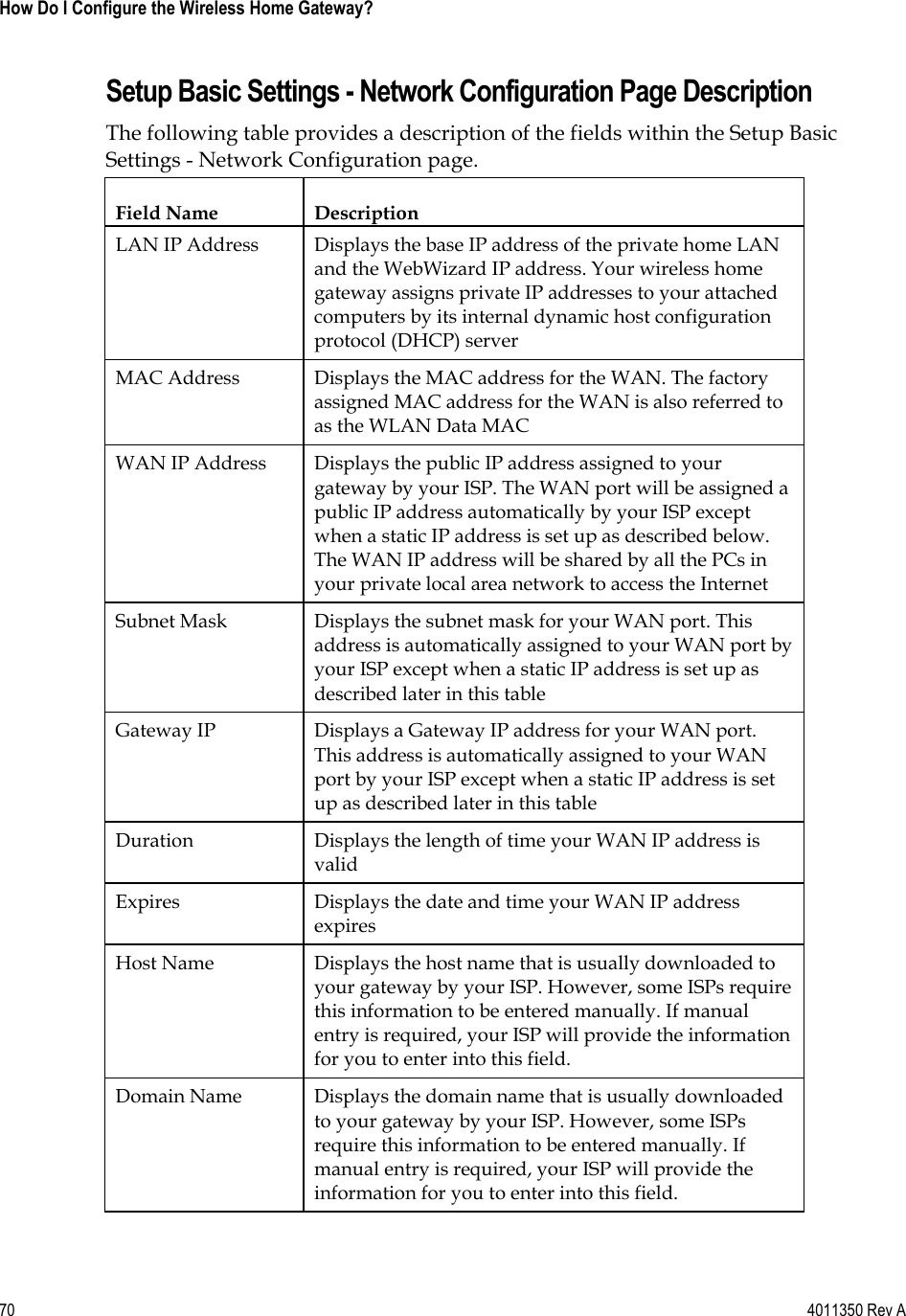
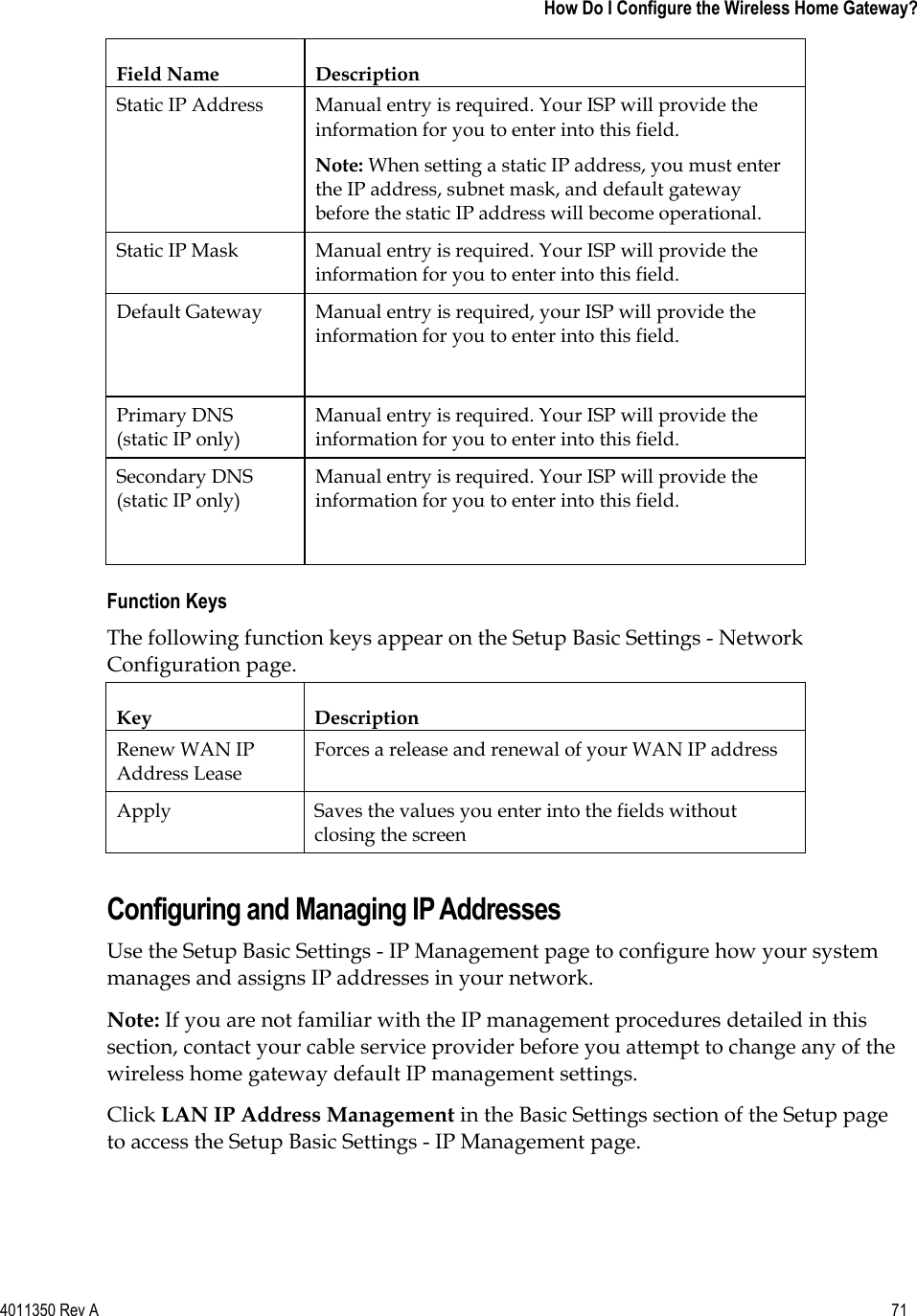
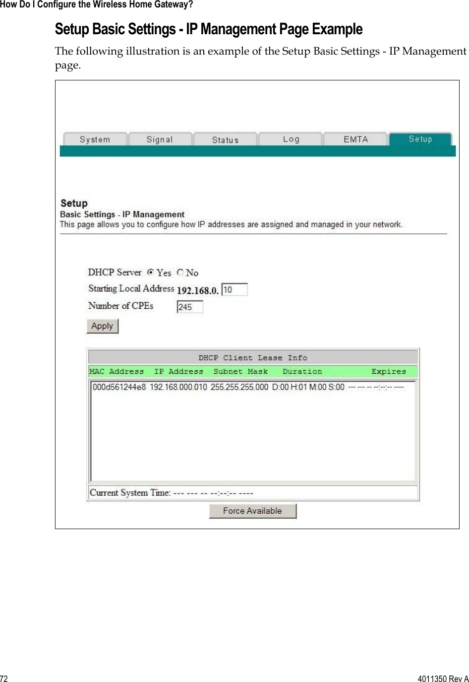
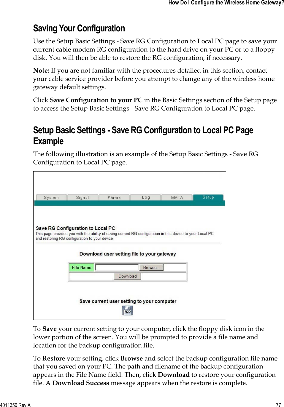
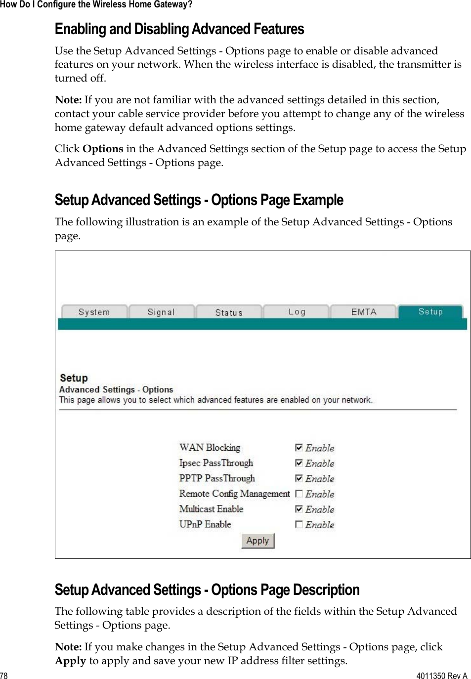
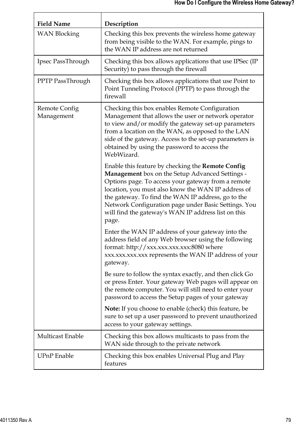
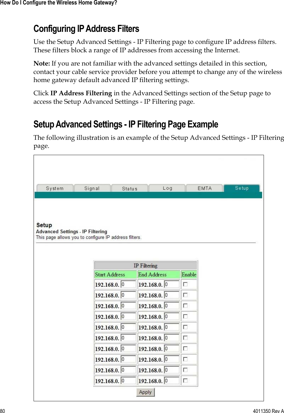
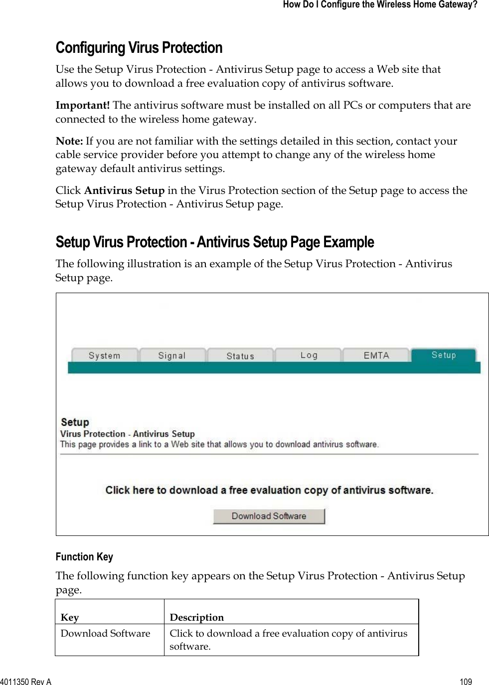
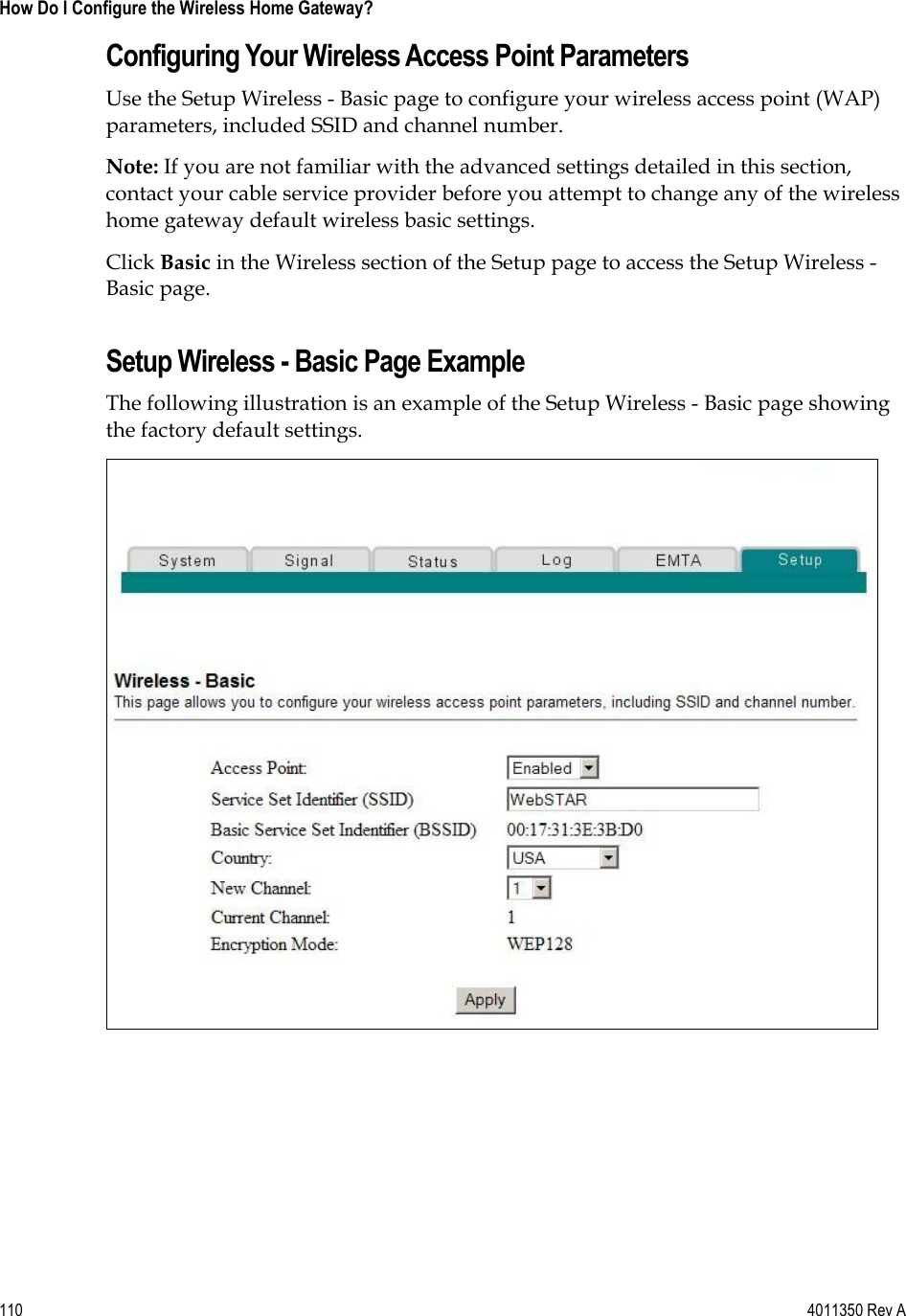
DPC2434 User Manual
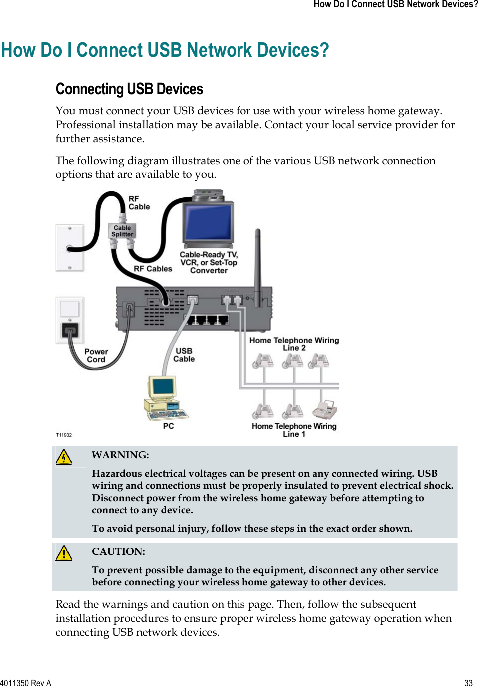
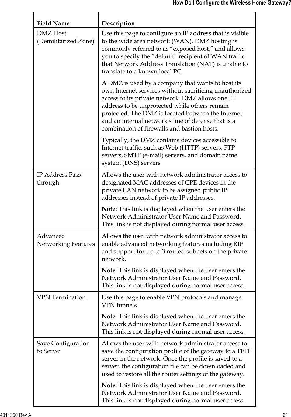
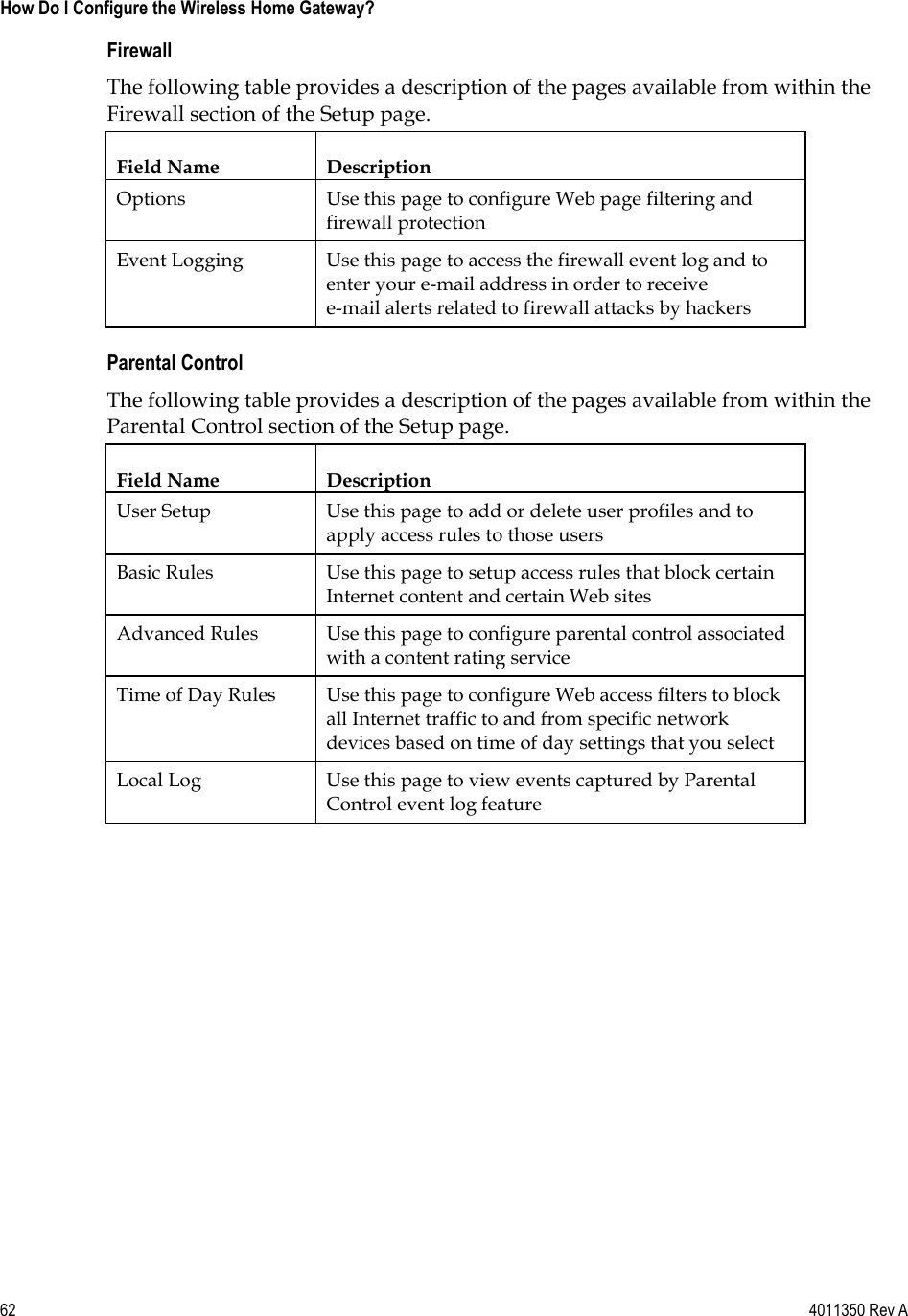
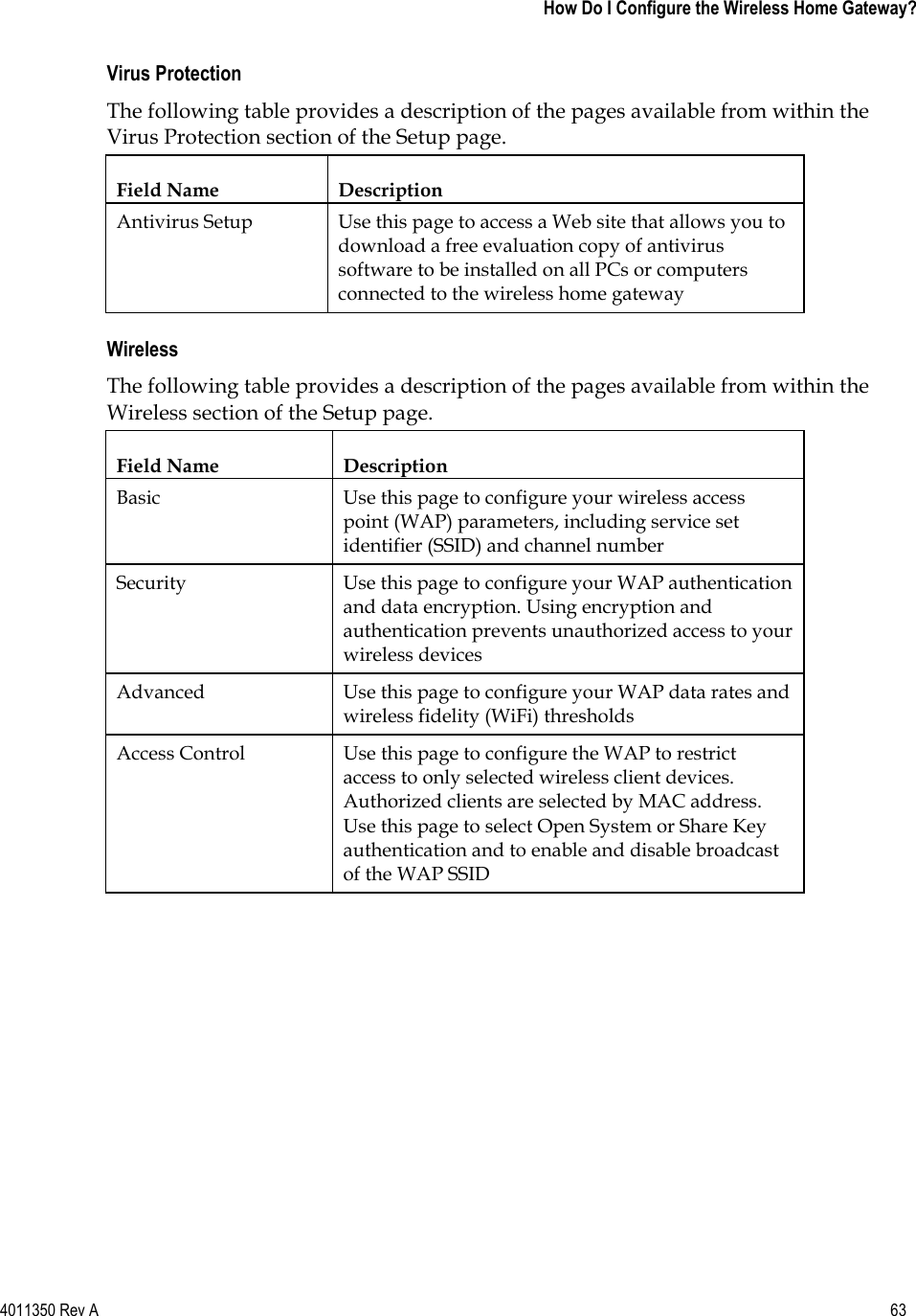
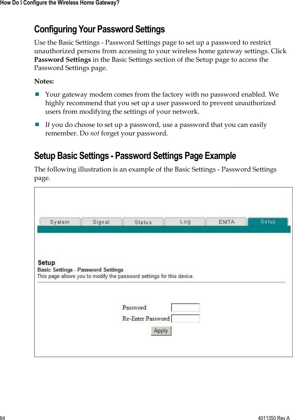
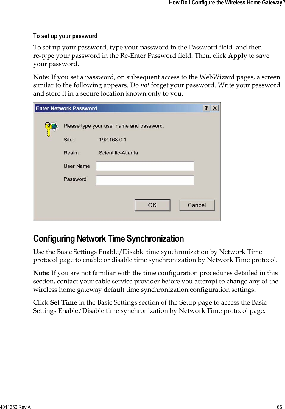
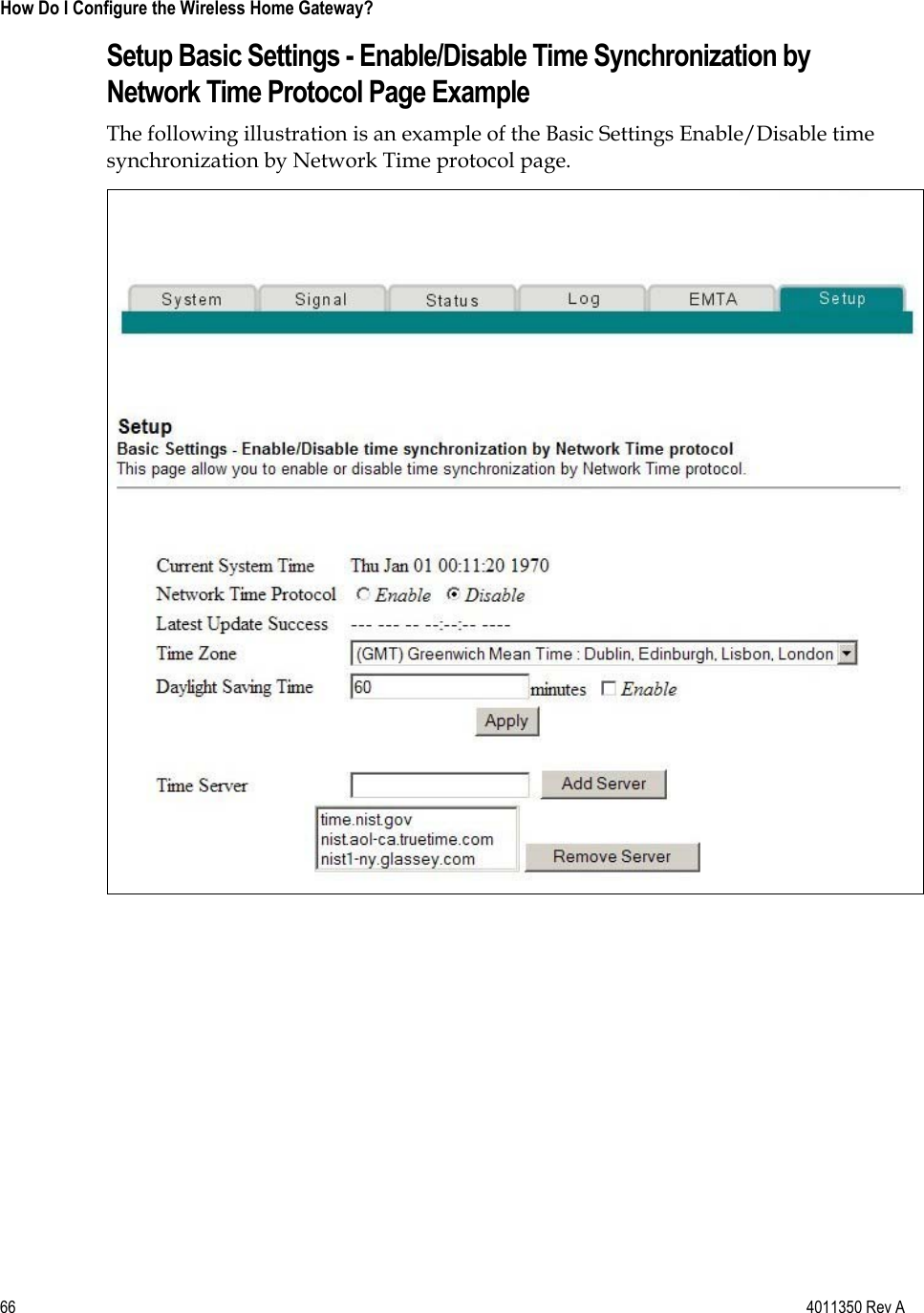
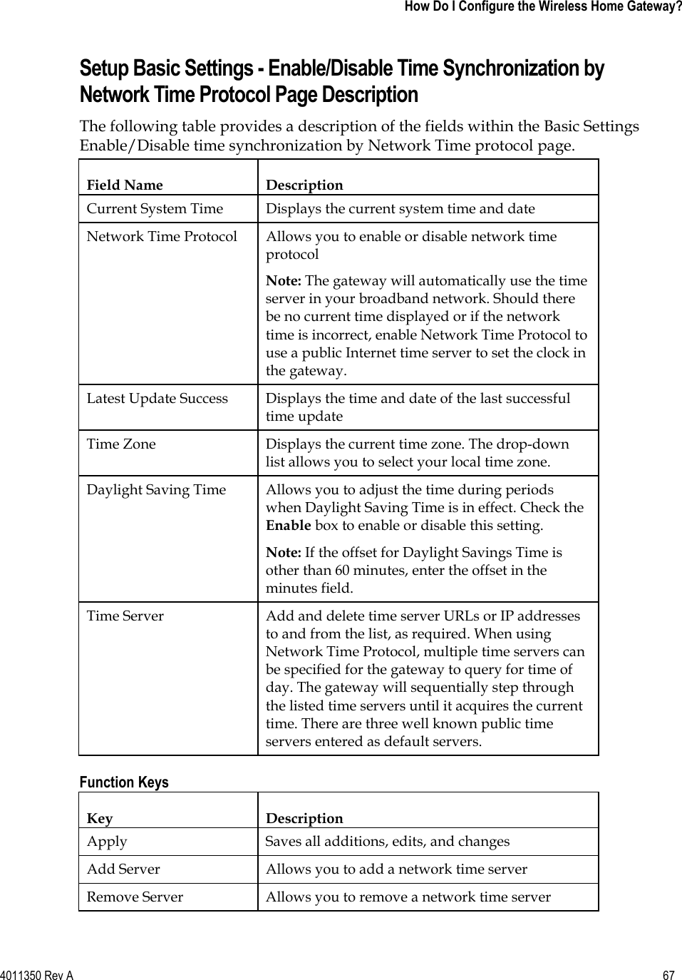
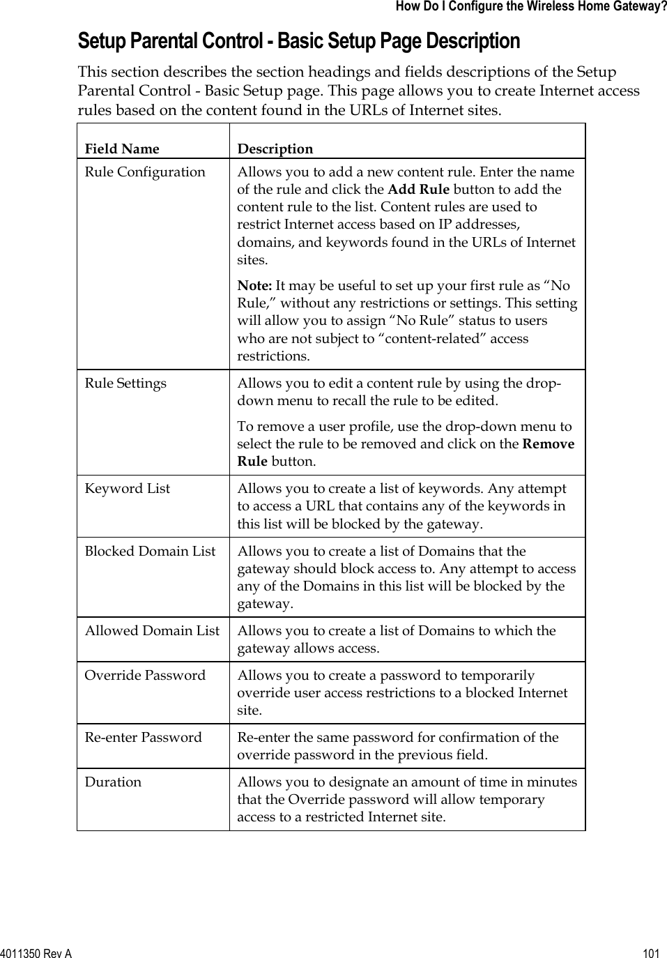
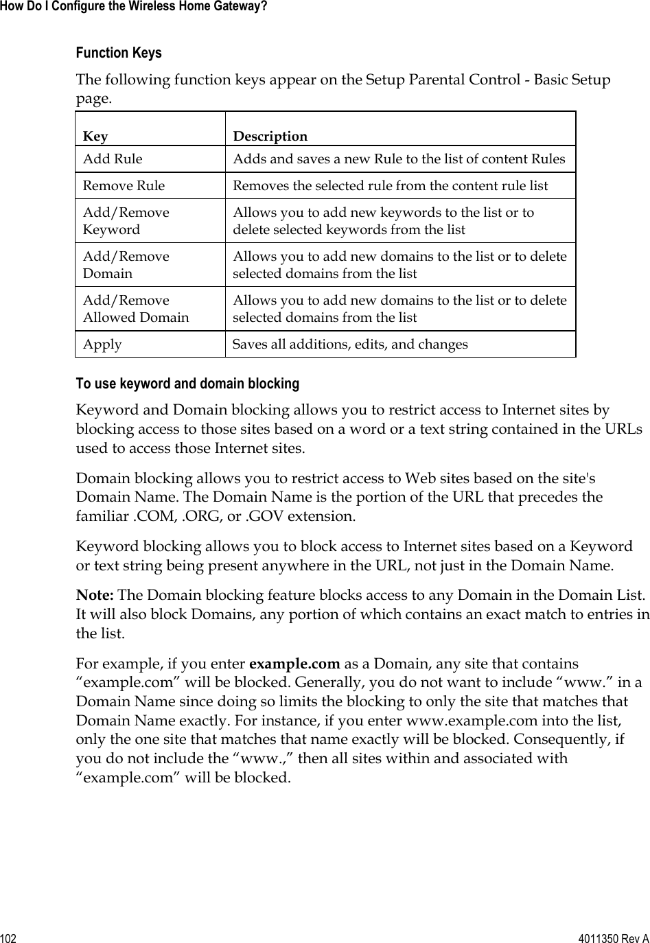
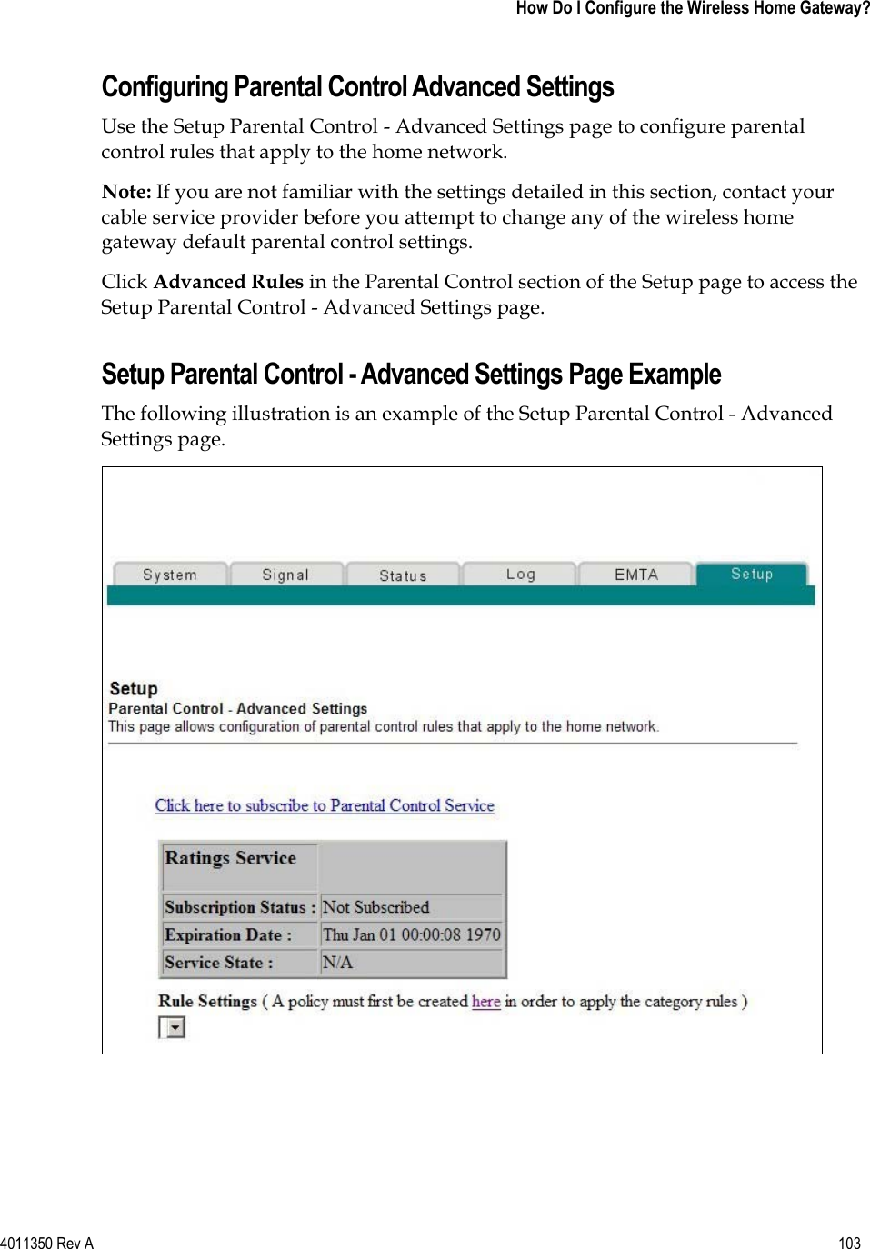
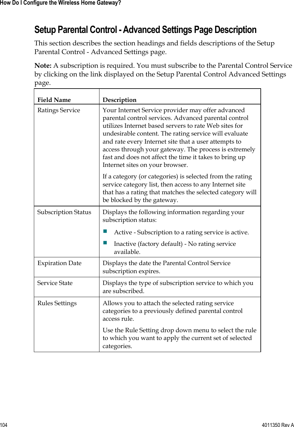
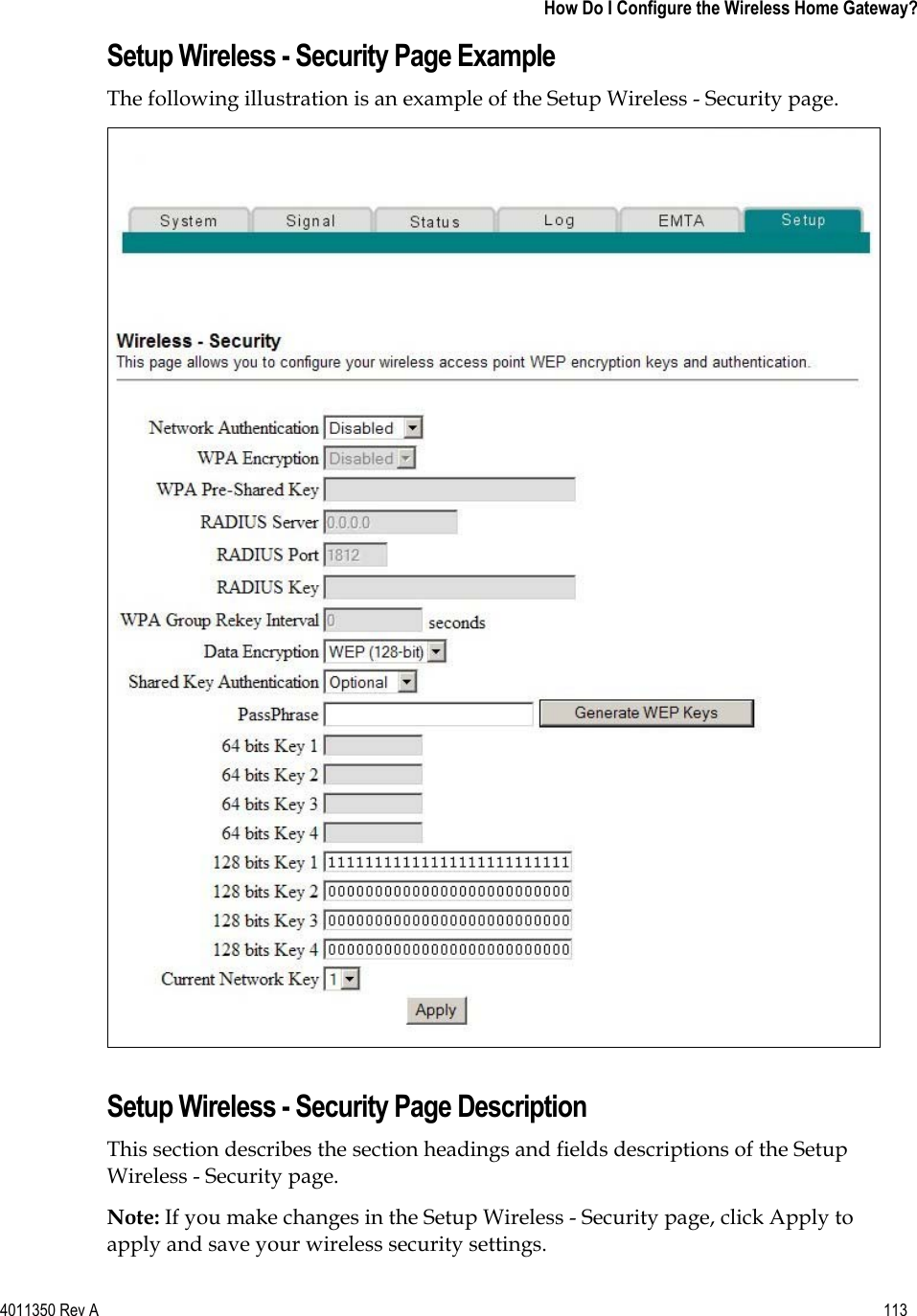
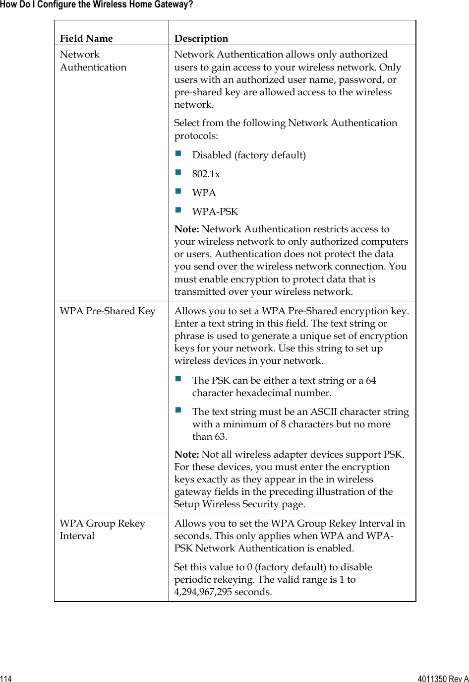
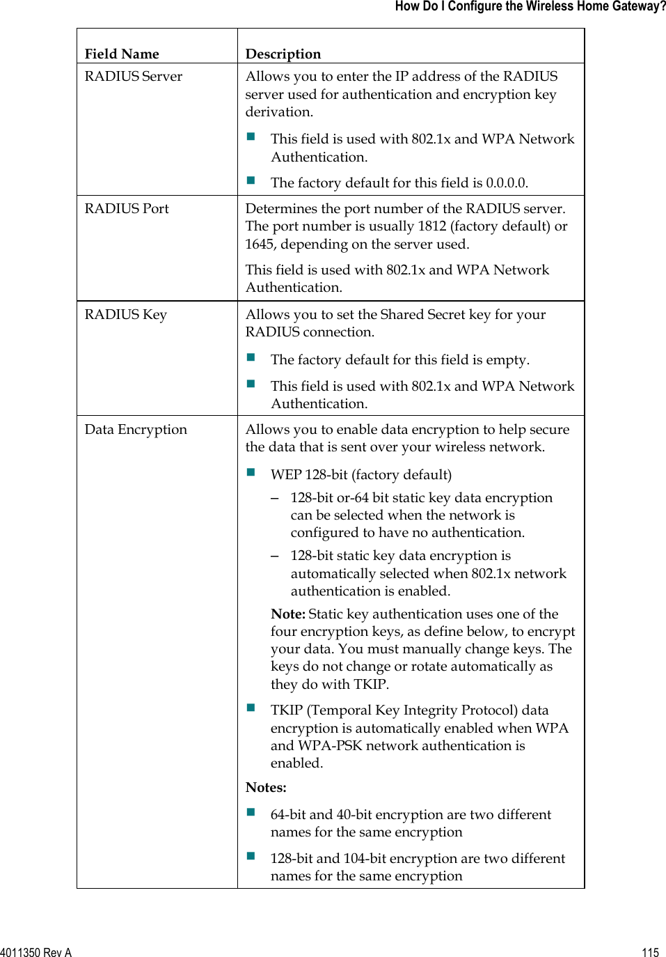
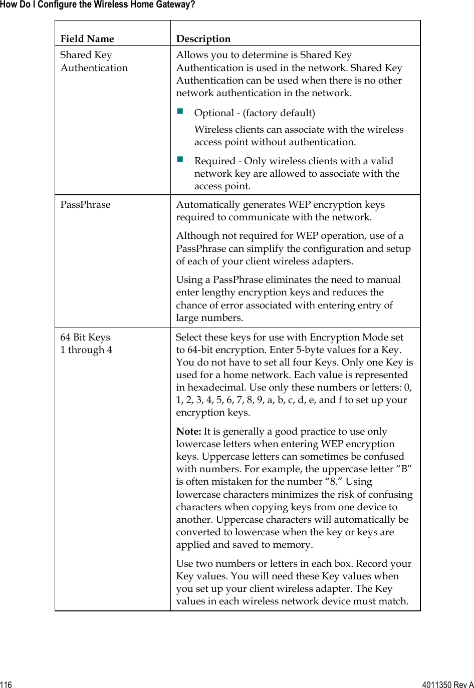
USERS MANUAL
Navigation menu
Upload a User Manual
Namespaces
Wiki Guide
HTML
PDF
Info
Views
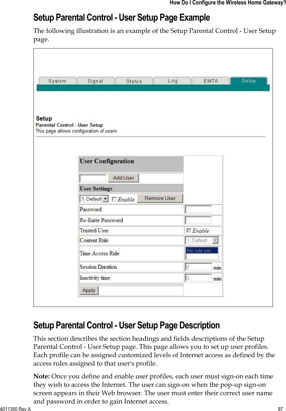
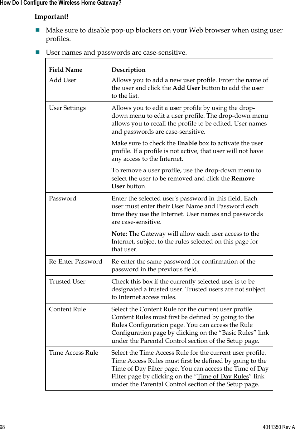
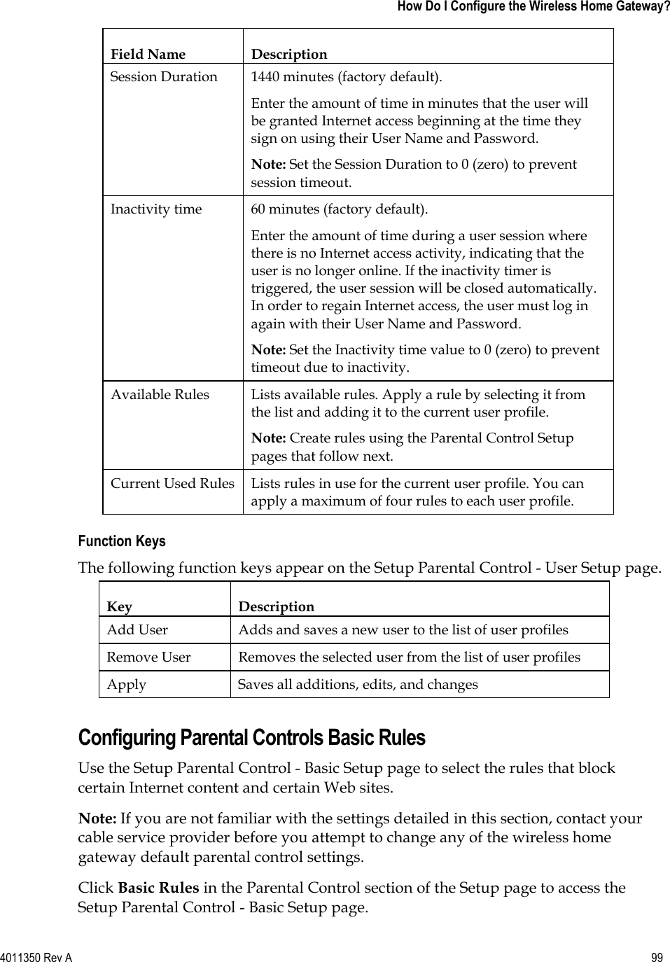
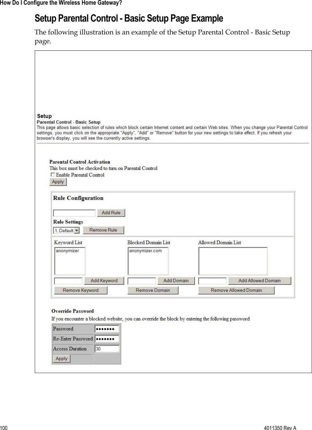
User Manual
Discussion / Help
Navigation